Abstract
A dilution tunnel was designed for the characterization of brake-wear particle emissions up to 10 μm on a brake dyno. The particulate matter emission levels from a single front brake were found to be 4.5 mg/km (1.5 mg/km being smaller than 2.5 μm) over a novel real-world brake cycle, for a commercial Economic Commission for Europe (ECE) pad. Particle Number (PN) emissions as defined in exhaust regulations were in the order of 1.5 to 6 × 10⁹ particles per km per brake (#/km/brake). Concentration levels could exceed the linearity range of full-flow Condensation Particle Counters (CPCs) over specific braking events, but remained at background levels for 60% of the cycle. Similar concentrations measured with condensation and optical counters suggesting that the majority of emitted particles were larger the 300 nm. Application of higher braking pressures resulted in elevated PN emissions and the systematic formation of nano-sized particles that were thermally stable at 350 °C. Volatile particles were observed only during successive harsh braking events leading to elevated temperatures. The onset depended on the type of brakes and their prehistory, but always at relatively high disc temperatures (280 to 490 °C).
1. Introduction
Airborne Particulate Matter (PM) has long been associated with environmental and health concerns [1]. Road transport has been identified as one of the major contributors to ambient PM, especially in urban environments [2,3]. PM emitted from motor vehicles can be classified to exhaust (by-products of incomplete combustion) and non-exhaust (brake and tire wear) sources. Automotive exhaust PM has been steadily decreasing as a result of continuously stringer regulations worldwide [4]. Non-exhaust PM sources are currently unregulated. Recent studies have identified brake-wear particles as main contributors to the transport PM emissions [5]. A recent review of the available literature on brake-wear emissions [6] suggested PM10 emission factors in the order of 6 to 7 mg/km for light duty vehicles and an order of magnitude higher for their heavy-duty counterparts. For reference, exhaust PM emission standards for light duty vehicles are currently set at 1.85 mg/km in USA with a target to further tighten them to 0.6 mg/km by 2028 in California. The corresponding limit in Europe is 5 mg/km, but has been augmented since 2015 by a Particle Number (PN) methodology as a means to extend particle emission standards well below the sensitivity of the gravimetric procedure (6 × 10¹¹ #/km).
Brake-wear particles have distinctly different physicochemical properties than exhaust aerosol. The mode of the mass-weighted size distribution of brake-wear aerosol is found to predominantly lie in the super-micron range, while exhaust aerosol is entirely in the submicron size range. Several studies, however, have reported that in addition to these super-micron particles originating from mechanical abrasion, large frictional heat generation can lead to release of nano-sized particles as small as 1.3 nm [7] through evaporation–condensation processes. The large variety in the available brake-pad formulations also implies differences in the chemistry and morphology of emitted particles [8,9,10]. Brake-wear particle composition and emission rates are also found to depend on the conditions under which braking occurs (severity of braking, temperature of the disc/pads, environmental conditions, etc.) [8,10,11,12].
Different approaches have been employed for the characterization of brake-wear emissions, ranging from on-road measurements [13] to chassis dynamometer [14], brake dynamometer [13,15,16] and pin-on disc configurations [17]. One of the major challenges in any measurement configuration relates to the inherent difficulties in sampling and transporting super-micron particles [13]. The complexity of the various available brake system configurations and the flow profiles around them, results in highly non-homogeneous concentration profiles that constitute collection of representative samples a daunting task.
The lack of a standardized sampling procedure and the use of different aerosol instrumentation makes it difficult to interpret published results on brake particle emissions. The main target of this work was to characterize brake-wear particle emissions using instrumentation employed in exhaust regulations, allowing for a direct comparison of the exhaust and non-exhaust emission levels from passenger cars, using four different types of brake pads. To this end, a dilution tunnel was designed that completely encloses the brake-system of a brake dynamometer. The tunnel was constructed to allow for sufficient mixing of the emitted brake-wear particles and minimize losses in the sub-10 μm size range. This sampling system allowed for a connection of standard measurement instrumentation employed in exhaust particle regulation measurements. This included a gravimetric filter box and a non-volatile (as defined in automotive exhaust regulation, that is particles surviving thermo-dilution at 350 °C) PN measurements system, employing both a 23 nm (current regulation) and a 10 nm (upcoming post-Euro 6 regulation) Condensation Particle Counter (CPC) in parallel. A dual-ejector dilution system with an intermediate Evaporation Tube (ET) at adjustable wall temperature was also employed to investigate the volatility of the emitted particles. A number of aerosol sizing instrumentation, including an Optical Particle Sizer (OPS) (TSI, Inc., Minnesota, USA), an Engine Exhaust Particle Sizer (EEPS)(TSI, Inc., Minnesota, USA), a Fast Particulate Analyser (DMS) (Cambustion, Ltd, Cambridge, UK), and an Electrical Low Pressure Impactor plus (ELPI) (Dekati, Ltd., Tampere, Finland), were also employed in dedicated tests to investigate the size of the emitted particles.
2. Materials and Methods
2.1. Brake Dyno and Dilution Tunnel
Four different types of brake pads of a mid-sized car (front brake) were tested in the study. Three of them were original equipment manufacturer (OEM) pads employed in the European Union and certified according to R90 regulation of the United Nations Economic Commission for Europe (UNECE) [18]. Two of them (ECE#1, ECE#2) had copper in their formulation while the third one (ECEcf) did not. The fourth brake pad tested had a Non-Asbestos Organic (NAO) formulation which is more commonly employed in the US, but can also be found in the aftermarket in Europe.
2.2. Brake Dyno and Dilution Tunnel
Brakes were tested on a brake dynamometer (Link 3900 NVH dynamometer) located at the Technical University of Ilmenau (TUI). The dynamometer has a 250 hp direct current (DC) drive and is installed in a fully air-conditioned test chamber. The vehicle can be simulated by mechanical and electrical inertia (up to 250 kg × m2). Testing is done with production brake and wheel assemblies. Braking is controlled with a hydraulic system capable of generating a maximum pressure of 200 bar.
The brake assembly was enclosed in a 80 cm × 45 cm × 76 cm (exchange time < 4 s) chamber that was designed to minimize particle losses [19]. A High Efficiency Particulate Air (HEPA H13) filter was installed at the inlet of the chamber. Airflow was controlled by a blower located downstream and could be adjusted in the 170 to 270 m3/h range (quantified at the beginning of the campaign via CO2 trace gas measurements). All tests were performed at the maximum tunnel flow of 270 m3/h. The flow was extracted through a duct assembly as shown in Figure 1a. The internal diameter of the duct down to the sample probes was 80 cm and was expanded to 16 cm downstream of the probes. Particle losses in the ducts from the chamber outlet to the sampling point were calculated using well established analytical expressions [20], taking into account gravitational settling, diffusion and inertial deposition in bends. The results of these calculations are summarized in Figure 1b. The 64% penetration at 10 μm would practically imply that the tunnel would act as a PM10 sampling system at 270 m3/h.
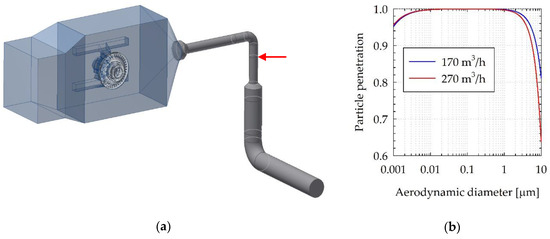
Figure 1.
(a) Layout of the dilution tunnel with red arrow indicating the location of the sample probes; (b) calculated particle penetration in the duct assembly down to the point where the sample probes are installed.
2.3. Brake Testing
All brakes were new and were first burnished by performing 20 repetitions of the World-harmonized Light duty Test Cycle (WLTC) cycle [21]. This test sequence was shown to stabilize particle emissions from new brakes [22]. The majority of the investigations were performed over selected modes of the AK master procedure established by the ArbeitsKreis (AK) working group representing European manufacturers of friction linings and passenger car brakes [23]. The same sequence, summarized in Table 1, was employed in all tests. The first mode (mode A hereinafter) consisted of 18 braking events from 80 to 30 km/h applying a constant disc pressure of 30 bar. The next mode (B) consisted of 8 braking events from 120 to 80 km/h, applying each time a progressively higher disc pressure, starting from 10 bar and incrementing it each time by 10 bar. The third mode (mode C) also consisted of 8 braking events from 200 to 170 km/h in which the braking pressure was again incremented each time by 10 bar, starting from 10 bar. Each braking event in these 3 modes, started after the disc temperature dropped to 100 °C. The disc temperature was measured by a thermocouple inserted in a hole in the rotor. The fourth mode (mode D) consisted of 15 consecutive brake events from 100 to 5 km/h at 30 bar without any waiting time between each brake. This mode, commonly referred as the fade procedure, aims at the evaluation of the brake performance at excessively high disc temperatures (that can exceed 600 °C). The sequence was concluded by a repetition of mode A, once the disc temperature following mode D, dropped to 100 °C.

Table 1.
Sequence of braking events in the selected AK master modes.
Selected tests were also performed over a novel test cycle [24] designed to better reflect real world braking conditions by means of analyzing 740,000 km of driving data from five different world regions. The specific cycle (hereinafter WLTP after the Worldwide harmonized Light-Duty vehicles Test Procedure database from which it was derived) consists of 303 stops over a total distance of 192 km and a net duration of ~4.5 hours. The cycle is split in 10 segments, separated by soak times to allow for the disc to reach the desired starting temperature. In the majority of the tests, the soak time was adjusted so that each segment started when the disc temperature dropped below 35 °C. Some dedicated investigations were also performed focusing only on the last and longest (1.5 hours and 65 km) segment of the cycle.
2.4. Particle Measurement and Sampling
Samples were extracted from the dilution tunnel using isokinetic probes compliant to EN 13284-1 and ISO 9096 (Paul Gothe, GmbH). The flows and nozzle diameters were selected to achieve an extracted to tunnel velocity ratio of 1 ± 0.1. A 90° bend probe design was used with the sample nozzle installed vertically facing the flow, with the bend occurring 10 cm downstream of the tip. Up to three probes were connected in the tunnel with the probe tips installed in the same plane and at a distance of 1 cm from the duct center and a minimum 90° from each other.
Particulate Matter (PM) emissions were determined gravimetrically using a filter holder for 47 mm filters. Teflon coated glass fiber filters (Pallflex TX40 HI20WW) were employed. Conductive Teflon (carbonated internal surfaces) tubing (60 cm long of 8 mm inner diameter) was employed to connect the sample probe to the filter holder. The majority of tests were performed without a cyclone (i.e., total PM) and a sample flowrate of 5 lpm was employed to minimize inertial impaction losses of supermicron particles. Dedicated tests were performed using a 2.5 μm cyclone (Mesa labs SCC2.354) on which the sample flowrate was increased to 8 lpm to match the cyclone specifications.
An AVL Particle Counter (APC) advanced was used to measure the Particle Number (PN) emissions in accordance to the automotive exhaust regulation [25], thus allowing for direct comparison with typical exhaust PN emission levels. Samples were first diluted 10 times in a flow-through rotating diluter using hot air at 150 °C, and then thermally treated in a Catalytic Stripper (CS) operating at 350 °C. A second 10:1 dilution with air at room temperature cooled down the sample bringing it to the appropriate concentration levels for the Condensation Particle Counters (CPCs). In addition to the default CPC (TSI 3790) having a 50% counting efficiency at 23 nm (APC@23), a second CPC (AVL CPC) having a 50% counting efficiency at 10 nm (APC@10), was employed sampling in parallel.
Two ejector diluters (Dekati, Ltd., Tampere, Finland) connected in series with an intermediate Evaporation Tube (ET) were also employed to investigate the effect of thermal treatment on the PN emissions. The two ejectors operated with conditioned air at ambient temperature providing a total dilution of ~35:1. Measurements were performed with the ET at 300 °C, 200 °C and at ambient temperature. PN concentrations were measured downstream of the second ejector with a TSI 3790, a TSI 3792, and a TSI 3776 CPC, having nominal 50% efficiencies at 23 nm (Ej@23), 10 nm (Ej@10) and 2.5 nm (Ej@2.5), respectively.
Real time size distribution measurements were also performed using both electrical and optical measurement techniques. The electrical techniques included a TSI 3090 Engine Exhaust Particle Sizer (EEPS), a Cambustion Fast Particle Analyzer (DMS) and a Dekati Electrical Low Pressure Impactor plus (ELPI). Optical measurement of the real time size distribution was performed with a TSI 3330 Optical Particle Sizer (OPS). The EEPS and DMS are electrical mobility spectrometers. Particles are first charged in a unipolar positive corona (which in the case of EEPS is preceded by a negative corona to condition pre-charged aerosol samples) and then electrostatically classified in a series of collection rings in an annular classifier. The number weighted electrical mobility size distribution is then calculated from the current measured by electrometers connected to the collection rings. The operating electrical mobility size range is 5.6 to 560 nm and 5 to 1000 nm for the EEPS and DMS, respectively. Both EEPS and DMS operated with their accompanied inlet cyclone to reduce multiple charge interferences of particles larger than 1000 nm, aerodynamic diameter. The ELPI is also using a unipolar corona charger to condition the particle charge but utilizes impactors (connected to sensitive electrometers) for size classification of the charged particles. The ELPI has 13 impactor stages and an absolute filter stage, covering the aerodynamic mobility size range of 6 nm to ~10,000 nm. The OPS measures light scattering of individual particles, with number being inferred from the count rate of the pulses and the size from the pulse height (scattered light power being a function of size, refractive index and shape of particles).
A miniCAST 6.203 C (Combustion Aerosol STandard) burner was also employed in some preliminary evaluation of particle losses inside the tunnel.
2.5. Test Protocol
Measurements were conducted in two separate campaigns employing different equipment. The first one focused on the investigation of PN emission levels using three different types of brake pads (ECE#1, ECEcf and NAO). The layout of the instrumentation employed is illustrated in Figure 2a. The ELPI and OPS were sampling through separate dedicated and isokinetic probes and were installed directly below them to minimize gravitational settling losses of supermicron particles that are measured with these instruments. A single sample probe was employed for the APC, the ejectors, the EEPS and the DMS, which were sampling through a TSI 3708 flow splitter. Inertial and gravitational losses are not so critical for the sub-micron size range covered by these instruments. Tests focused on the sequence of AK master modes described in Section 2.3 (Table 1). Five (NAO) to nine (ECE#1, ECEcf) repetitions of this sequence were performed, adjusting the ET temperature of the ejector dilution system between tests (toggling between ambient, 200 and 300 °C wall temperature). One repetition of the WLTP cycle were also performed using the ECE#1 brake pads.
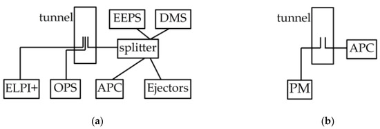
Figure 2.
Experimental setup employed in the (a) first and (b) the second phase of the measurement campaign.
The second campaign focused on the assessment of the emission repeatability with the novel WLTP cycle. Accordingly, the instrumentation was confined to a gravimetric filter and the APC to optimize sampling (avoid any disturbances and potential enhanced losses caused by the use of many probes and flow splitters). Furthermore, the equipment was confined to the same instrumentation used in automotive exhaust measurements, to allow for a direct comparisons of the emission levels (Figure 2b).
The dynamometer settings employed in the two campaigns are summarized in Table 2. These are representative of braking in the left front wheel of a mid-sized car.

Table 2.
Dynamometer settings employed in the two measurement campaigns.
Two approaches were employed for the experimental assessment of particle losses inside the tunnel. In the first approach, the entire soot aerosol generated by the miniCAST burner was introduced in the tunnel through two silicon tubes (1 m long each with 4 mm internal dimeter connected to a single 3 m long silicon tube installed on the burner) the outlet of which was fixed at the two brake pads facing the disc. The tunnel was set at the employed flow (270 m3/h) and the disc was rotating at a speed corresponding to 50 km/h. The soot concentration was measured with the APC at the outlet of the miniCAST (before connecting it to the tunnel) and after dilution in the tunnel, at the sampling point (red arrow in Figure 1a). Measurements were performed with an isokinetic probe installed at 4 positions on the same horizontal plane, 90° apart and all at a distance of 1 cm from the center of the duct. The miniCAST was operating at a mode producing dry particles with a mode at 65 nm and a geometric standard deviation of 1.7, measured separately before the campaign with a TSI Scanning Mobility Particle Sizer (SMPS) 3996L76. The overall transportation efficiency of the entire sampling system was also performed gravimetrically following the procedure described by Augsburg et al. [19]. A pre-weighted fine dust (class M5) filter was installed at the tunnel, directly downstream of the sampling point, and a full WLTP test was performed. The mass collected on the filter corresponds to the fraction of brake wear reaching the sampling point. Subsequent evacuation of deposited particles by compressed air onto the outlet filter allowed for the quantification of the brake-wear deposited on the ducts, enclosure, brake components (caliper, wheel carrier) and finally disc and pads.
2.6. Calculations
Since the sequence of braking in the AK master mode is temperature controlled, and thus the duration of each mode can change between repeats, the total number particles being emitted over each individual brake event was calculated as the integral of the product of PN concentration times tunnel flow. On the other hand, since the ten segments of the WLTP cycle have a well-defined speed profile, it was possible to calculate emission rates per km for each segment. That is, the total number of particles emitted over each segment (resulting from integrating the product of concentration times the tunnel flow) was divided by the total distance driven. In the case of PM, a single filter was employed over the entire WLTP cycle. The PM emission rate was determined by scaling the collected mass by the ratio of tunnel flow to extracted flow, and then dividing it with the total distance covered by the entire cycle.
3. Results
3.1. Particle Penetration Measurements
The total flow of the soot aerosol exiting the miniCAST was 10.47 lpm (determined by summing all mass flow controller flows in the burner) at the settings employed in the campaign. At the tunnel flowrate of 270 m3/h this corresponds to an overall dilution ratio of 430:1. The dilution-corrected concentrations measured with the APC@10 at the sample point, were at 93% of the concentrations measured with the same instrument at the outlet of the miniCAST burner. The concentrations measured at the four different sampling points agreed within ±1%, verifying that the aerosol is well mixed at the sampling location. The measured concentrations at the outlet of the miniCAST were 3.5 × 10⁷ #/cm3. The number concentration reduction due to polydisperse coagulation inside the relatively long silicon tubing (4 m long with 4 mm internal diameter) used to connect the aerosol to the dilution tunnel, is calculated [20] to be 7% for the geometric mean diameter (55 nm) and geometric standard deviation (1.7) of the CAST aerosol. Therefore, the lower concentrations measured at the sampling point could be attributed to coagulation.
Figure 3a summarizes the total PM recovery results from a WLTP test with ECE#2 brake pads. The method managed to recover ~90% of the deposited total PM, with 57% collected on the gravimetric filter. The majority of the total emitted PM was found to be deposited on the assembly (18%) and the enclosure chamber (11%) with only 3% being deposited in the ducts of the tunnel. It should be stressed that the specific methodology provides the aggregate losses for all particle sizes of the total PM. A visual inspection (Figure 3b) of the cyclone employed in subsequent testing of the same brake pad (ECE#2) over segment 10 of the WLTP cycle, revealed the presence of visible chunks of deposits, suggesting that particles larger than 10 μm are emitted and transported through the tunnel to the sampling lines.
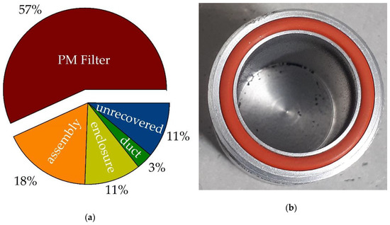
Figure 3.
(a) Recovery of total PM emitted over a repetition of the WLTP cycle with ECE#2 brake pads; (b) photo of the 2.5 μm cyclone installed in front of the PM filter holder after three repetitions of WLTP segment 10.
3.2. Particle Emissions over the WLTP Following the Regulated Exhaust Measurement Procedures
Figure 4 provides an overview of the PN emissions over the six WLTP repetitions with the ECE#2 pads. The cycle-average PN emissions (Figure 4a) were found to be less than 3 × 10⁹ #/km per brake, that is, more than 200 times below the exhaust PN limit. The actual concentrations inside the tunnel (Figure 4b) remained close to background levels (280 #/cm3 at 10 nm and 180 #/cm3 at 23 nm) during the constant speed cruising section of the cycle. Accordingly, emissions remained at background levels for more than ~60% of the test. Subtraction of background from the results (that can be justified on the basis of the relatively low number concentrations and short residence time in the tunnel that would hinder coagulation), suggested that on average background contributed to 33% ± 4% and 40% ± 6% of the cycle-average 23 and 10 nm PN emission rates. With the background subtracted, the 23 nm and 10 nm emissions agreed within 1% ± 1%, which is within the calibration accuracy. Background correction also improved the repeatability of the measurements from 16% to 6% for the 10 nm CPC and from 11% to 6% for the 23 nm CPC.
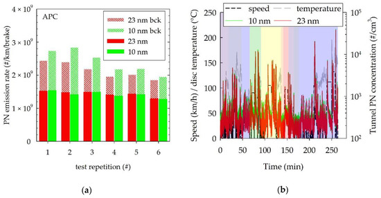
Figure 4.
(a) Cycle average PN emission rates over 6 repetitions of the WLTP cycle for ECE#2 pads as determined with APC@10 and APC@23. The dashed sections of the bars illustrate the contribution of background; (b) example real time traces of the APC@10 and APC@23 (test #3).
Figure 5a provides a summary of the total PM emissions over the WLTP using ECE#2 pads. The total PM emission rate was determined to be 4.8 ± 0.04 mg/km/brake. Dedicated tests over the 10th segment of the cycle in which a 2.5 μm cyclone was also installed (Figure 5b), suggested that only ~30% of the total PM was PM2.5.
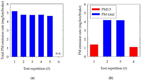
Figure 5.
(a) Total PM emissions over 5 repetitions of the WLTP cycle for ECE#2 pads; (b) comparison of total PM and PM2.5 emissions over 4 repetitions of segment 10 of the WLTP cycle for ECE#2 pads.
3.3. Size of Brakewear Particles Emitted over WLTP
A WLTP cycle was also performed in the first measurement campaign, with ECE#1 brake pads. The ET of the ejectors was kept at ambient temperature during this test. The number emission rates calculated with the various PN instruments employed is summarized in Figure 6a. The PN emissions following the R83 procedure, where found to be at 5.6 × 10⁹ #/km/brake with both CPCs, suggesting that no small particles were present. The 10 and 23 nm CPCs sampling from the dual ejector system measured ~7% lower emissions (5.1 and 5.6 × 10⁹ #/km/brake, respectively) despite the fact that the sample was not thermally treated. This apparent inconsistency is indicative of an overestimation of the particles losses with the R83 procedure for the emitted particles. The R83 losses are calculated as the average losses at 30, 50 and 100 nm, that were found to best reproduce mean losses for typical diesel exhaust having a mode at 50–70 nm. As particle losses increase with decreasing particle size, the losses will be overcompensated if the emitted particles have a larger mean size. The cycle-average emissions measured with the OPS were 11–17% lower than those of the CPCs, but this difference can be entirely associated with the saturation of the OPS at ~6000 #/cm3 (Figure 6b). Based on the CPC traces, a 6000 #/cm3 saturation would result in 22% underestimation.
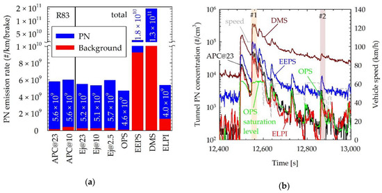
Figure 6.
(a) Cycle-average PN emissions over a WLTP test with ECE#1 pads with different instruments. Numbers in each bar correspond to the background-corrected PN emissions. The default inversion matrix has been used for the TSI Engine Exhaust Particle Sizer (EEPS), while Dekati Electrical Low Pressure Impactor plus (ELPI) concentrations were determined assuming an effective particle density of 1 g/cm3; (b) comparison of the real time traces of APC@23, TSI Optical Particle Sizer (OPS), EEPS, ELPI and Cambustion Fast Particulate Analyser (DMS) over a section of segment 10 of the test.
From the electrical spectrometers employed, the ELPI yielded the best agreement with the CPCs, suggesting a cycle-average emission rate of 4.0 × 10⁹ #/km/brake. The two electrical mobility spectrometers (DMS and EEPS) exhibited considerably higher noise levels exceeding the actual emissions in the tunnel, by 50% (EEPS) to 200% (DMS). This can be seen for example in the real time traces shown in Figure 6b. The fact that the emission events lying below the instrumentation noise levels were detected by both EEPS the DMS is a consequence of the dependence of the noise level on the size bin. While the electrometer noise is the same in all stages, the upper stages collect smaller particles that carry less charge. The zero levels of these two instruments was also found to raise following high emission events, suggesting a drift of their electrometers.
The real time traces reveal two type of emission events. Particle are emitted both following a braking event but also during acceleration of the disc from a full stop. The latter have been associated with detachment of wear particles previously deposited on the surface of the brake and grooves through brake drag [15]. Such particle generation due to brake drag could also explain the relative slow decay of particle concentrations after braking.
Figure 7 compares size distributions measured with the various instruments employed for two example emission events. The first one (#1 in Figure 6b) corresponds to the largest emission spike over the cycle, corresponding to a sequence of 4 (gradual) braking events from 105 km/h to 40 km/h within 50 s. The second one (#2 in Figure 6b) corresponds to a more moderate sequence of braking events from 60 km/h to 25 km/h within 40 s. The electrical mobility size distributions measured with the DMS and the EEPS using the default inversion matrix, suggested a similar mode at ~140 nm for both events. While the recovered distributions were similar, the DMS measured ~5 times higher concentrations. The use of the compact and soot inversion matrices in EEPS software resulted in a shift of the mode to 180 and 185 nm, and a change of the number concentration by +15% and −45%, respectively.
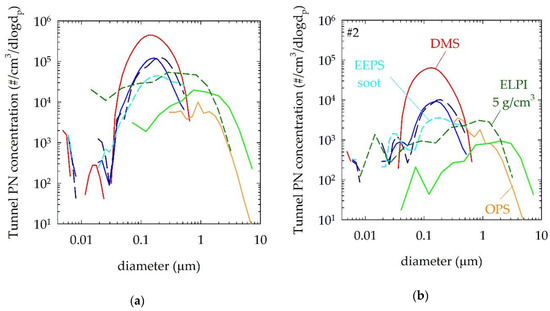
Figure 7.
(a) Comparison of the EEPS, DMS, OPS and ELPI size distributions during the largest emission event (braking from 105 km/h—section #1 in Figure 6b) over the WLTP test with ECE#1 pad. ELPI results were calculated for constant effective densities of 1 and 5 g/cm3 thus allowing direct comparison with the mobility size distributions of EEPS and DMS. EEPS distribution were calculated using all available inversion matrices (default, compact particles and soot particles); (b) corresponding size distributions over a moderate braking event (braking from 60 km/h—section #2 in Figure 6b).
Calculating the electrical mobility size distribution from the ELPI, requires an assumption on the effective particle density, which in general may vary with particle size [26]. The effect is illustrated in Figure 7 where ELPI number distributions for both a constant density of 1 g/cm3 (default setting) and 5 g/cm3 (estimated wear debris density [13]). In contrast to the DMS and the EEPS, the ELPI suggested a large shift of the size distribution which for the default unit density assumption, was from ~700 nm at section #1 to 1150 nm at section #2. The corresponding modes for an effective density of 5 g/cm3 shifted to 240 nm and 440 nm, respectively, and were accompanied by an ~4-fold increase in the number concentrations.
The OPS classifies individually counted particles according to their optical properties (refractive index and shape). Given the uncertainties in comparing optical particle size with electrical mobility, it is difficult to directly compare OPS with the other instrumentation. Nevertheless, the OPS distributions suggest that more than 90% of the individually detected particles are smaller than 1 μm, thus within the measurement range of the CPCs. Considering the good agreement between OPS and CPC concentrations, this suggests that most of the particles should lie in the 300 to 1000 nm range.
3.4. Nanoparticle Formation and Volatility over AK Master
Figure 8 compares the number of total (ejectors operating at ambient temperature) and non-volatile (APC with a CS at 350 °C) particles emitted in three repetitions of mode B for ECE, ECEcf and NAO pads. The emission levels were found to depend strongly on the type of brake pad and the applied pressure. NAO pads gave the lowest PN emissions, producing approximately 3 × 10⁷ particles per braking event, irrespective of the applied pressure. The emission levels were similar with and without thermal pre-treatment, while all CPCs measured practically the same. On the other hand, ECE and ECEcf pads resulted in at least one order of magnitude higher emissions than NAO pads (>108 #). The actual emissions increased with increasing disc pressure (i.e., harsher braking events) by more than an order of magnitude (reaching up to 1010 #). Such more aggressive braking events were also found to result in excess particle counts with the low cut-off CPCs, indicating the formation of nanoparticles. Similar levels of excess particle counts were detected downstream of the APC and the dual ejector system, suggesting that the produced particles survive thermal treatment in the CS at 350 °C. While the formation of nanoparticles was persistent in all repetitions, the actual increase in emission levels differed from repetition to repetition. The peak disc temperature ranged between 145 and 180 °C for ECE and ECEcf pads, and between 145 and 170 °C for NAO pads. No trend could be identified between number of emitted particles and peak disc temperature.
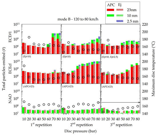
Figure 8.
Comparison of total particle number emissions over mode B (120 km/h to 80 km/h braking at different disc pressures) as a function of braking pressure, as measured with different CPCs with (APC) and without (Ej@25 °C) thermal pre-treatment. Dots indicate the maximum disc temperature over each braking event. Missing data due to technical issues are indicated in parentheses.
Figure 9 compares the number of total (ejectors operating at ambient temperature) and non-volatile (APC with a CS at 350 °C) particles emitted in three repetitions of mode C for ECE, ECEcf and NAO pads. Braking at the higher vehicle speed of this mode (200 km/h) led to elevated particle emissions. At the lowest applied pressure (10 bar), ECE and ECEcf pads produced ~2 × 10⁹ #, while NAO pads emitted 4 × 10⁹ #, and there was no indication of nanoparticle formation with all CPCs measuring similar particle number concentrations. Application of higher pressures resulted in a more consistent formation of nanoparticle, this time for all pads, including NAOs. The excess particle counts measured with the 10 nm CPCs were similar both for the ejector and the APC systems, suggesting that these particles are thermally stable. Peak disc temperatures increased by approximately 15 °C, compared to the deceleration events at 120 km/h (Figure 8), but within this dataset there was no clear correlation between peak disc temperature and emission levels.
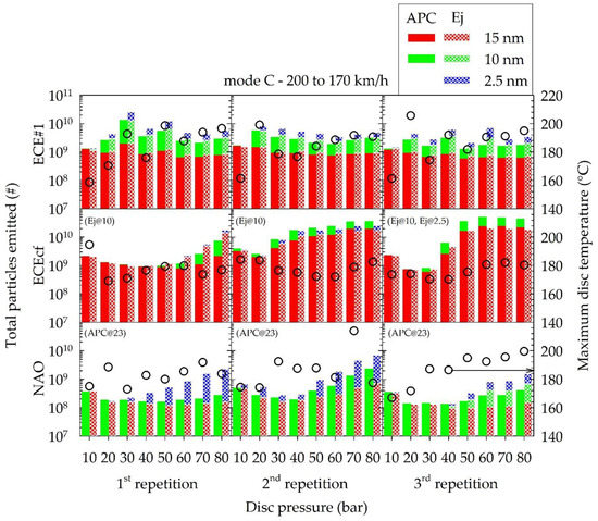
Figure 9.
Comparison of total particle number emissions over mode C (200 km/h to 170 km/h braking at different disc pressures) as a function of braking pressure, as measured with different CPCs with (APC) and without (Ej@25 °C) thermal pre-treatment. Dots indicate the maximum disc temperature over each braking event. Missing data due to technical issues are indicated in parentheses.
Volatile particle formation was consistently observed over the fade events (mode D). A distinctly different emission performance was observed between the first and subsequent repetitions of mode D, as shown in Figure 10. In all cases, the concentration traces of the 10 nm CPC sampling thermally treated (APC with CS at 350 °C) and untreated (ejector operating without heaters) were very similar over the first couple of braking events. Eventually though, the thermally untreated samples resulted in higher number concentrations, suggesting the presence of volatile particles that either evaporates in the CS of the APC or shrinks to sizes below the detection limit of the 10 nm CPCs. The onset of this release of volatile particles depended on the type of brake pad but also on the prehistory. In particular, volatile particles consistently appeared earlier in the sequence, during the first repetition of mode D for all brake pads tested. In particular, the release of volatile particles occurred at disc temperatures of ~350, 280 and 280 °C in the first mode D test, compared to ~490, 490 and 380 °C in subsequent tests of ECE, ECEcf and NAO pads. Furthermore, in the case of the ECEcf but especially the ECE formulation, the overall emissions were significantly reduced following the first repetition of this braking sequence. It should be noted that the limited dilution of the dual ejector system (~35:1) lead to saturation of the CPCs over the last sections of most of the tests. The higher volatile formation potential with the NAO pads over the fade sequence and their lower PN emissions over the remaining AK master operating conditions, compared to ECE pads is consistent with the lower wear rates and poor fade performance of the former [13].
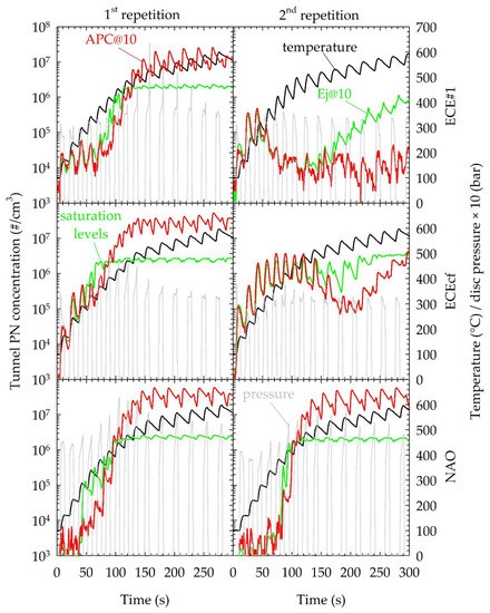
Figure 10.
Comparison of real time traces of disc temperature and thermally treated (APC) and untreated (ejector) concentrations measured with the 10 nm CPCs, over the first and the second repetition of mode D for different brake pads.
Emission levels were more repeatable after the first mode D test, allowing for a more detailed investigation of the volatility of the emitted particles. As an example, Figure 11 compares the traces of the CPCs and EEPS over three repetitions of mode D with ECE pads. The APC was always treating particles in the CS at 350 °C, and the EEPS was always sampling untreated aerosol. The ET in the ejectors’ dilution system was adjusted at different temperatures in each repetition, namely 25 (upper panel), 200 (middle panel) and 300 °C (lower panel). The traces of the 23 nm CPCs downstream of the two sampling systems were similar over then entire sequence of mode D (10 min). The 10 nm CPCs, measured higher concentrations than the 23 nm ones from the start of the sequence. Over the first 10 braking events, similar concentrations were measured downstream of the APC and the ejector systems, irrespective of the ET temperature of the latter, suggesting that some thermally stable nanoparticles were being formed. At the end of the 10th braking event, with the disc temperature exceeding 530 °C, the 10 nm CPC of the ejectors’ system started measuring progressively higher concentrations, with the difference decreasing as the ET temperature progressively increased. The EEPS concentrations remained similar between repetitions. Therefore, the closer agreements between the two 10 nm CPCs is indicative of the presence of particles that are removed with thermal treatment.
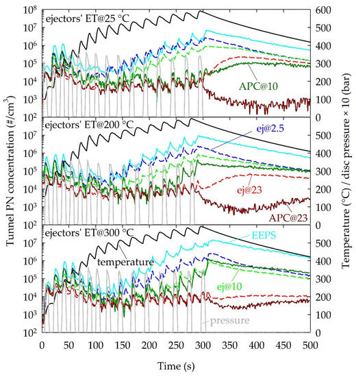
Figure 11.
Comparison of real time emission traces over three repetitions of mode D with ECE pads, at different temperature settings of the ET of the ejectors’ dilution system. In addition to the CPC traces, the total number concentrations measured with the EEPS are also shown to illustrate the repeatability of total particle number emissions between repetitions. The pressure and disc temperature traces are also shown.
The emission traces suggest that the volatile nanoparticles have a different origin. More specifically, in the first 6 to 7 braking events where no such particles are evident, the emissions are found to raise during the actual application of a pressure on the brakes. During the subsequent braking events, in addition to a concentration spike during the actual application of a pressure, a second concentration spike is observed in the 10 nm CPCs following the release of pressure. In the last six braking events, the concentration peaks after the pressure is released are much higher and even overshadow those during the actual application of a braking pressure. At the end of the 15 consecutive braking events, the disc temperature reached nearly 600 °C and then gradually decreased at a rate of ~1 °C/s. Only the APC@23 showed a reduction in number concentrations during this period. The ej@23 registered an increase in concentrations approaching the levels of the low cut-off size CPCs that showed a moderate decrease for more than 200 s after the pressure was released. Increasing the temperature of the ejectors’ ET mostly affected the ej@23, whose readings approached those of the APC@23.
4. Discussion
One of the objectives of the study was to quantify the brake-wear particle emissions over the recently developed brake-dyno cycle from the WLTP data set, following the regulated exhaust measurement procedures. Tests focused on a set of ECE brake pads employed in the European market (ECE#2). PM emissions determined with a tunnel designed to achieve ~60% penetration at 10 μm, were found to range as high as 5 mg/km per front brake for the ECE pads tested. Considering that the two front brakes typically handle 70% of the braking load [27], the PM10 fingerprint of a typical passenger car would be more than 2 × 5 = 10 mg/km. Approximately, 30% of the PM emitted with these pads was PM2.5. These levels compare well to published data, although it is well established that PM emissions can differ significantly for different pad formulations [6,27]. The measured emission rates are also in good agreement with the emission factors of 4.4 to 10 mg/km total PM and 1.7 to 3.9 mg/km per passenger car suggested in the emission inventory guidebook of the European Environment Agency [28].
While the visible large chunks of particles collected on the 2.5 μm cyclone confirm the high penetration of super-micron particles in the established tunnel, it is not clear how much they contributed to the measurements without a cyclone at the end of the campaign. Their origin may be accumulated deposits on the edge of the brake-pads that were visible after prolonged testing. This would imply that their contribution may change over time.
To our knowledge, this is the first study reporting also PN emissions over the novel WLTP brake cycle, following the regulated exhaust methodology. The PN emission levels were found to be at ~1.5 × 10⁹ #/km/brake after subtracting the background levels. There was no evidence of nanosized particles being formed, with both the 23 and 10 nm CPCs measuring the same concentrations. The peak concentration levels measured in the dilution tunnel were in the order of 40,000 #/cm3. The prolonged operation at constant speed driving resulted in concentrations lying at background levels (~200 #/cm3) for ~60% of the time with the novel cycle. These results are consistent with the observations of Mathissen et al. [24] that particle concentrations remained at the much higher noise levels of the ELPI over the novel cycle, when tested on a tunnel operating at similar volumetric flowrate (250 m3/h).
PN emissions were however found to strongly depend on the type of brake pads and the operating conditions. A WLTP test with a different type of ECE pads (ECE#1) resulted in 4 times higher emission rates (~6 × 10⁹ #/km/brake). The use of a low-losses sampling system consisting of two ejector diluter, with no thermal pre-treatment resulted in identical emission levels even with a 2.5 nm CPC.
Interpretation of the distributions measured by the real time sizing techniques is difficult due to the lack of information on the properties of the emitted brake-wear particles. All sizing instrumentation suggested that nano-sized particles were not formed over the WLTP cycle, confirming the good agreement between the concentrations detected by CPCs with different cut-off sizes. The good agreement between the OPS and CPCs when concentrations remained within the measurement range of the OPS, suggests that emitted particles are larger than 300 nm. The electrical mobility analyzers however (DMS and EEPS), suggested that the emitted particles had a mode in the 140 nm to 180 nm, depending on the inversion matrix used. The noise level of both instruments exceeded the cycle average concentrations, and there was also indication of electrometer drifts over the course of the test. Even with the noise level removed, the concentrations were overestimated especially by the DMS (2050% compared to 200% in the case of the EEPS). This could be indicative of an underestimation of particle size, since in principle the number concentration would be inversely proportional to the charging efficiency, which increases with particle size. The systematically higher concentrations measured with the DMS compared to the EEPS may be indicative of the existence of pre-charged particles that are differently handled by the different types of chargers [29]. Namely, EEPS utilizes a tandem negative–positive corona charger while the DMS only utilizes positive corona charger. The ELPI exhibited lower noise levels and the default inversion assuming unit-density particles resulted in a better agreement with the reference counting techniques (33% lower concentrations from CPCs, OPS). However, the ELPI distributions strongly depend on the assumed particle density which is largely unknown. For example, calculations using a density of 5 g/cm3 (close to the suggested value by [13]), result in a 4-fold increase in number concentrations and a 450 to 700 nm shift of the mode to smaller sizes.
More aggressive braking events, and specifically the application of higher braking pressures was found to systematically result in the release of nanosized particles, as evident from the higher particle counts registered with the low cut-off size CPCs. These nano-particles were found to be thermally stable at 350 °C for both ECE, copper-free ECE and NAO pads tested. Their concentration levels were generally found to increase with increasing disc pressure, but did not correlate with the peak disc temperature that remained below ~200 °C, and similar to peak temperatures reached over the WLTP cycle.
The peak disc temperature is commonly suggested as an indicator for the onset of thermal release of material from the brakes [14,16,24]. However, this lumped parameter does not properly represent the actual temperature on the contact area between pads and disc. The heat being released over a given braking sequence, will be similar irrespective of the applied pressure. However, higher pressures will result in faster heat release, leading in locally higher temperatures. Heat conduction in the brake disc will establish the bulk disc temperature that the thermocouple measures, and which eventually will be similar irrespective of the applied braking pressure.
Volatile particles were only observed over the fade sequence of the AK master test cycle, which includes consecutive harsh braking events. Their formation took place at elevated temperatures, with the exact onset depending of the type of brake pad and its prehistory. More specifically, the formation potential was found to reduce following the first fade event. The formation potential was higher on NAO pads, although this still required disc temperatures in excess of 280 °C during the first repetition and ~380 °C in subsequent tests. Such a shift in the onset of their formation was observed with all pad materials tested. This behavior could simply reflect release of the more volatile compounds of the brake lining in the first run [16]. However, considering the relatively high temperatures achieved at the end of the sequence (~600 C), it is also possible that chemical restructuring of the brake pads took place.
The concentrations of these volatile particles were found to peak after the pressure on the disc was released, and they continued to be released at the end of the sequence when disc temperature was gradually decreasing from a peak 600 °C. Therefore, their formation mechanism cannot be linked to mechanical abrasion. The use of an evaporating tube at 200 °C removed some of these particles, and a further increase to 300 °C resulted in similar concentrations to those of the APC operating with a CS at 350 °C. It should be stressed, that for volatile particles to be removed in the CS, they must be evaporated at the operating CS temperature of 350 °C. Therefore, there may be organic compounds in the released material that survive the CS.
To our knowledge there is no published data on the emissions over the novel WLTP cycle. Chassis dyno measurements of PN over the Los Angeles City Traffic (LACT) cycle were reported to systematically result in large number of volatile particles being released that were efficiently removed by a CS [14]. Non-volatile PN emissions (3 × 10⁹ #/km/brake) were within the range of what we measured over the WLTP. The authors attributed the formation of volatile particles to the relatively high disc temperatures produced in the brake enclosure used that did not allow for efficient cooling of the brake assembly. However, formation of volatile PN emissions over the LACT were also reported on brake dyno measurement with sampling systems similar to the one employed in the present study (dilution tunnel operating at 250 m3/h) at disc temperatures as low at 170 °C. A common observation in these studies was that the formation potential decreased over time leading to large test to test variabilities. It is not clear whether this systematic observation of volatile particles over the LACT is merely caused by differences in the pad formulations employed in the different studies or it reflects different emission behavior from the WLTP procedure. The LACT cycle includes more aggressive braking events and much higher braking durations [16].
5. Conclusions
The study illustrated that it is possible to design a tunnel that would allow quantification of PM emissions larger than 2.5 μm. Analysis of the mass deposits revealed that the design of the enclosure is the most critical component. PM2.5 emissions from a single front brake, contributing to less than 50% of the total brake-wear emission fingerprint, were found to be ~1.3 mg/km over a real-world driving cycle (WLTP) for a commercial ECE pad. The emitted brake-wear particles were found to be relatively large (with optical counters measuring similar concentration levels with CPC) and withstand thermal treatment at 350 °C. Particle number emissions over WLTP were in the order 1.5 to 6 × 10⁹ #/km/brake for ECE pads. Peak concentration levels (~40,000 #/cm3) could exceed the linearity range of full-flow CPCs over specific braking events, but remained at background levels for 60% of the cycle. Application of higher braking pressures resulted in elevated PN emissions and systematic formation of nano-sized particles that were thermally stable at 350 °C. Volatile particles were observed only during the fade sequence of the AK master. Their formation was linked to the established temperature, as evident from their continuing production after the disc pressure was released. The onset was found to depend on the pad formulations and the prehistory of the pads, but in all cases at higher disc temperatures (~280 to 490 °C) from that observed over the WLTP.
Author Contributions
Conceptualization, A.M., M.A.; methodology, A.M., M.A., D.H. and K.A.; formal analysis, A.M.; writing—original draft preparation, A.M.; writing—review and editing, M.A. and D.H.; supervision, A.M., M.A. and K.A.
Funding
This research received no external funding.
Conflicts of Interest
The authors declare no conflict of interest.
References
- Pope, C.A.; Dockery, D.W. Health effects of fine particulate air pollution: Lines that connect. J. Air Waste Manag. Assoc. 2006, 56, 709–742. [Google Scholar] [CrossRef]
- Pope, C.A., III. Lung Cancer, Cardiopulmonary Mortality, and Long-term Exposure to Fine Particulate Air Pollution. JAMA 2002, 287, 1132–1141. [Google Scholar] [CrossRef]
- Oberdörster, G.; Maynard, A.; Donaldson, K.; Castranova, V.; Fitzpatrick, J.; Ausman, K.; Carter, J.; Karn, B.; Kreyling, W.; Lai, D.; et al. Principles for characterizing the potential human health effects from exposure to nanomaterials: Elements of a screening strategy. Part. Fibre Toxicol. 2005, 2, 8. [Google Scholar] [CrossRef]
- Pant, P.; Harrison, R.M. Estimation of the contribution of road traffic emissions to particulate matter concentrations from field measurements: A review. Atmos. Environ. 2013, 77, 78–97. [Google Scholar] [CrossRef]
- Thorpe, A.; Harrison, R.M. Sources and properties of non-exhaust particulate matter from road traffic: A review. Sci. Total Environ. 2008, 400, 270–282. [Google Scholar] [CrossRef]
- Grigoratos, T.; Martini, G. Brake wear particle emissions: A review. Environ. Sci. Pollut. Res. 2015, 22, 2491–2504. [Google Scholar] [CrossRef]
- Nosko, O.; Vanhanen, J.; Olofsson, U. Emission of 1.3–10 nm airborne particles from brake materials. Aerosol Sci. Technol. 2017, 51, 91–96. [Google Scholar] [CrossRef]
- Mosleh, M.; Blau, P.J.; Dumitrescu, D. Characteristics and morphology of wear particles from laboratory testing of disk brake materials. Wear 2004, 256, 1128–1134. [Google Scholar] [CrossRef]
- Wahlström, J.; Olander, L.; Olofsson, U. Size, Shape, and Elemental Composition of Airborne Wear Particles from Disc Brake Materials. Tribol. Lett. 2010, 38, 15–24. [Google Scholar] [CrossRef]
- Kukutschová, J.; Moravec, P.; Tomášek, V.; Matějka, V.; Smolík, J.; Schwarz, J.; Seidlerová, J.; Šafářová, K.; Filip, P. On airborne nano/micro-sized wear particles released from low-metallic automotive brakes. Environ. Pollut. 2011, 159, 998–1006. [Google Scholar] [CrossRef] [PubMed]
- Kwak, J.; Kim, H.; Lee, J.; Lee, S. Characterization of non-exhaust coarse and fine particles from on-road driving and laboratory measurements. Sci. Total Environ. 2013, 458, 273–282. [Google Scholar] [CrossRef] [PubMed]
- Olofsson, U.; Olander, L. On the identification of wear modes and transitions using airborne wear particles. Tribol. Int. 2013, 59, 104–113. [Google Scholar] [CrossRef]
- Sanders, P.G.; Xu, N.; Dalka, T.M.; Maricq, M.M. Airborne brake wear debris: size distributions, composition, and a comparison of dynamometer and vehicle tests. Environ. Sci. Technol. 2003, 37, 4060–4069. [Google Scholar] [CrossRef] [PubMed]
- Mathissen, M.; Grigoratos, T.; Lahde, T.; Vogt, R. Brake wear particle emissions of a passenger car measured on a chassis dynamometer. Atmosphere 2019, 10, 556. [Google Scholar] [CrossRef]
- Hagino, H.; Oyama, M.; Sasaki, S. Laboratory testing of airborne brake wear particle emissions using a dynamometer system under urban city driving cycles. Atmos. Environ. 2016, 131, 269–278. [Google Scholar] [CrossRef]
- Zum Hagen, F.H.F.; Mathissen, M.; Grabiec, T.; Hennicke, T.; Rettig, M.; Grochowicz, J.; Vogt, R.; Benter, T. Study of Brake Wear Particle Emissions: Impact of Braking and Cruising Conditions. Environ. Sci. Technol. 2019, 53, 5143–5150. [Google Scholar] [CrossRef]
- Wahlström, J.; Söderberg, A.; Olander, L.; Jansson, A.; Olofsson, U. A pin-on-disc simulation of airborne wear particles from disc brakes. Wear 2010, 268, 763–769. [Google Scholar] [CrossRef]
- UNECE. UNECE Regulations No. 90 (Agreement Concerning the Adoption of Uniform Technical Prescriptions for Wheeled Vehicles, Equipment and Parts Which Can Be Fitted and/or Be Used on Wheeled Vehicles and the Conditions for Reciprocal Recognition of Approvals Granted on the Basis of These Prescriptions); UNECE: Geneva, Switzerland, 2012. [Google Scholar]
- Augsburg, K.; Hesse, D.; Feißel, T.; Wenzel, F.; Germanow, P. Cfd Based Analysis of Particle-Air Interaction within a Sampling Device for Brake Dust Emissions. In Proceedings of the Eurobrake 2018, The Hague, Netherlands, 22–24 May 2018; FISITA (UK) Limited: Stansted, Essex, 2018. [Google Scholar]
- Kulkarni, P.; Baron, P.A.; Willeke, K. (Eds.) Aerosol Measurement: Principles, Techniques, and Applications; Wiley: Hoboken, NJ, USA, 2011; ISBN 978-0-470-38741-2. [Google Scholar]
- Tutuianu, M.; Bonnel, P.; Ciuffo, B.; Haniu, T.; Ichikawa, N.; Marotta, A.; Pavlovic, J.; Steven, H. Development of the World-wide harmonized Light duty Test Cycle (WLTC) and a possible pathway for its introduction in the European legislation. Transp. Res. Part D Transp. Environ. 2015, 40, 61–75. [Google Scholar] [CrossRef]
- Augsburg, K.; Hesse, D.; Kuhn, U.; Reicht, R. Influence of regenerative braking on the emission behavior of friction brakes 2018. In Proceedings of the 48th PMP Meeting, Ispra, Italy, 7–8 November 2018. [Google Scholar]
- SAE J2522 Dynamometer Global Brake Effectiveness 2014. Available online: https://www.sae.org/standards/content/j2522_201409/ (accessed on 22 October 2019).
- Mathissen, M.; Grochowicz, J.; Schmidt, C.; Vogt, R.; Farwick zum Hagen, F.H.; Grabiec, T.; Steven, H.; Grigoratos, T. A novel real-world braking cycle for studying brake wear particle emissions. Wear 2018, 414–415, 219–226. [Google Scholar] [CrossRef]
- UNECE. UNECE Regulations No. 83 Uniform Provisions Concerning the Approval of Vehicles with Regard to the Emission of Pollutants According to Engine Fuel Requirements 2012; UNECE: Geneva, Switzerland, 2012. [Google Scholar]
- Maricq, M.M.; Xu, N. The effective density and fractal dimension of soot particles from premixed flames and motor vehicle exhaust. J. Aerosol Sci. 2004, 35, 1251–1274. [Google Scholar] [CrossRef]
- Garg, B.D.; Cadle, S.H.; Mulawa, P.A.; Groblicki, P.J.; Laroo, C.; Parr, G.A. Brake Wear Particulate Matter Emissions. Environ. Sci. Technol. 2000, 34, 4463–4469. [Google Scholar] [CrossRef]
- European Environment Agency. EMEP/EEA Air Pollutant Emission Inventory Guidebook 2016: Technical Guidance to Prepare National Emission Inventories; European Environment Agency: Copenhagen, Denmark, 2016; ISBN 978-92-9213-806-6. [Google Scholar]
- Schwelberger, M.; Mamakos, A.; Fierz, M.; Giechaskiel, B. Experimental assessment of an electrofilter and a tandem positive-negative corona charger for the measurement of charged nanoparticles formed in selective catalytic reduction systems. Appl. Sci. 2019, 9, 1051. [Google Scholar] [CrossRef]
© 2019 by the authors. Licensee MDPI, Basel, Switzerland. This article is an open access article distributed under the terms and conditions of the Creative Commons Attribution (CC BY) license (http://creativecommons.org/licenses/by/4.0/).