Article

Self-Adjusting Look-Ahead Distance of Precision Path Tracking for High-Clearance Sprayers in Field Navigation

1
School of Agricultural Engineering, Jiangsu University, Zhenjiang 212013, China
2
School of the Environment and Safety Engineering, Jiangsu University, Zhenjiang 212013, China
3
School of Architectural Decoration and Art Design, Jiangsu Vocational College of Electronics and Information, Huaian 223003, China
4
School of Computer Science and Communication Engineering, Jiangsu University, Zhenjiang 212013, China
5
Key Laboratory for Theory and Technology of Intelligent Agricultural Machinery and Equipment, Jiangsu University, Zhenjiang 212013, China
6
Jiangsu Province and Education Ministry Cosponsored Synergistic Innovation Center of Modern Agricultural Equipment, Jiangsu University, Zhenjiang 212013, China
*
Author to whom correspondence should be addressed.
Agronomy 2025, 15(6), 1433; https://doi.org/10.3390/agronomy15061433
Submission received: 16 April 2025 / Revised: 4 June 2025 / Accepted: 9 June 2025 / Published: 12 June 2025
(This article belongs to the Special Issue Robotics and Automation in Farming)

Abstract

:
As a core component of agricultural machinery autonomous navigation, path tracking control holds significant research value. The pure pursuit algorithm has become a prevalent method for agricultural vehicle navigation due to its effectiveness at low speeds, yet its performance critically depends on the selection of the look-ahead distance. The conventional approaches require extensive parameter tuning due to the complex influencing factors, while fixed look-ahead distances struggle to balance the tracking accuracy and adaptability. Considerable effort is required to fine-tune the system to achieve optimal performance, which directly affects the accuracy of the path tracking and the results in the cumbersome task of selecting an appropriate goal point for the tracking path. To address these challenges, this paper introduces a pure pursuit algorithm for high-clearance sprayers in agricultural machinery, utilizing a self-adjusting look-ahead distance. By developing a kinematic model of the pure pursuit algorithm for agricultural machinery, an evaluation function is then employed to estimate the pose of the machinery and identify the corresponding optimal look-ahead distance within the designated area. This is done based on the principle of minimizing the overall error, enabling the dynamic and adaptive optimization of the look-ahead distance within the pure pursuit algorithm. Finally, this algorithm was verified in simulations and bumpy field tests under various different conditions, with the average value of the lateral error reduced by more than 0.06 m and the tuning steps also significantly reduced compared to the fixed look-ahead distance in field tests. The tracking accuracy has been improved and the applicability of the algorithm for rapid deployment has been enhanced.

1. Introduction

The automatic navigation systems of agricultural machinery primarily consist of two components—autonomous navigation control and autonomous operation control [1]. Among these, autonomous navigation technology, as one of the core technologies for agricultural mechanization and intelligentization, has become an inevitable direction for the development of modern agricultural equipment [2,3]. Currently, the autonomous navigation and intelligent operation systems developed based on RTK-GNSS high-precision positioning technology have been widely adopted [4,5]. As the primary machinery for chemical and fertilizer application in large-scale farmland operations in China, high-clearance sprayers hold significant importance for their autonomous upgrading [6]. This advancement enables autonomous path following capabilities, effectively addressing the technical limitations of traditional manual operation modes, such as ensuring the operation quality by preventing missed or overlapping sprays while reducing labor costs [7,8,9,10].
Agricultural autonomous navigation technology primarily encompasses three core research areas—navigation pose acquisition, path planning, and path tracking control. As a critical component of autonomous navigation systems, the research on path tracking control algorithms is of particular importance [11]. Therefore, some researchers have already conducted studies on path tracking algorithms for agricultural machinery autonomous navigation control [12,13,14]. Li et al. examined the motion dynamics between the chassis of agricultural machinery and various soil types, and created a kinematic model to design a path tracking control algorithm using a sliding mode variable structure for robot tracking [15]. Wang et al. [16] addressed the slip effect in agricultural vehicle navigation by developing an extended kinematic modeling approach based on conventional kinematic models. Specifically targeting automatic navigation systems for agricultural tractors, this study significantly enhanced the anti-interference capability and path tracking accuracy of agricultural machinery under complex terrain conditions through the introduction of a slip compensation mechanism [16]. Cui et al. developed an adaptive fuzzy Stanley algorithm that dynamically adjusts the control parameters based on lateral or heading deviations, enhancing the curvature adaptability and reducing the convergence distance compared to conventional methods, meeting full-field agricultural navigation requirements [17].
The pure pursuit algorithm is a path tracking method that simulates human drivers’ look-ahead behavior. It converts lateral position deviations into steering commands, enabling vehicle motion control [18]. Due to its simplicity, high computational efficiency, and ease of engineering implementation, this algorithm has been widely applied in path tracking control within agricultural machinery autonomous navigation systems [19]. Iida et al. and Kurita et al. developed an autonomous navigation system for rice harvesters that utilizes the pure pursuit algorithm to facilitate spiral harvesting across entire fields, maintaining a straight line tracking error rate of less than 0.1 m at a speed of 0.6 m/s [20,21].
In the pure pursuit algorithm, the look-ahead distance is a crucial parameter that influences the selection of the target point, and as a result it plays a major role in the path tracking performance. Due to its importance, optimizing this parameter has become a central focus of research [22,23,24]. Huang et al. [25] proposed an enhanced pure pursuit algorithm integrating self-adjusting look-ahead distance adjustment with PID control. The method employs a speed–curvature coupling model for real-time look-ahead distance optimization and utilizes a PID controller to smooth the steering angle output, achieving 15.13 cm reductions in lateral and heading errors, respectively, thereby significantly improving the low-speed path tracking stability [25]. Macenski et al. [26] effectively addressed the adaptability issue of existing methods in variable speed scenarios by introducing a linear velocity dynamic adjustment mechanism based on the classic adaptive pure pursuit algorithm. This algorithm is specifically optimized for the safety navigation needs of service robots in confined spaces, significantly improving the path tracking safety in complex environments [26]. Choi et al. [27] proposed a self-adjusting look-ahead distance-based vehicle lateral control method that adaptively adjusts the look-ahead distance through a speed–curvature coupling model while achieving stable path tracking via linear parameter-varying control. The simulation results demonstrated that this method significantly improves the tracking accuracy compared to conventional fixed-parameter approaches [27]. Kamal et al. proposed a novel cooperative look-ahead lane change (Co-LLC) system for autonomous vehicles, which optimizes AV lane-changing behavior and achieves a 22% improvement in traffic throughput [28].
In the studies mentioned earlier on the look-ahead distance in the pure pursuit algorithm, this has been primarily applied to autonomous vehicles, while there are also distinct research achievements in the field of agricultural machinery autonomous navigation. Zhang et al. [29] developed a nonlinear PID path tracking control system with multi-parameter optimized feedback for rice harvesters. By dynamically adjusting the distance parameters, the system achieved standard tracking deviations of 0.033 m on concrete and 0.032 m on muddy fields, representing a 26% performance improvement over conventional fixed-gain algorithms [29]. In their work, Li Ge and colleagues factored both the instantaneous speed of the agricultural machinery and the curvature of the desired path into the look-ahead distance model. This adaptive adjustment within the pure pursuit algorithm led to improved path following accuracy for the transplanter [30]. Yang et al. [31] addressed the challenge of look-ahead distance optimization in agricultural autonomous navigation by proposing an optimal-goal-point-based path tracking algorithm. Simulations and multi-condition field tests demonstrated that this method reduces tracking errors by over 20% compared to conventional pure pursuit algorithms, significantly improving the path tracking accuracy [31]. Fu Xiaobo et al. [32] proposed a predictive pure pursuit algorithm optimized with PSO for wheeled harvesters, which dynamically adjusts the look-ahead distance by constructing predictive membership functions for heading or lateral errors combined with an adaptive weighting mechanism. Field tests with a corn harvester demonstrated that the tracking accuracy fully meets the operational requirements for precision farming [32]. Zhang et al. proposed an improved pure-pursuit-based path tracking algorithm for agricultural machinery that employs adaptive PSO optimization to dynamically adjust the look-ahead distance, significantly enhancing the straight line tracking accuracy [33].
Based on the above research, although the pure pursuit algorithm and its key parameter (look-ahead distance) have made certain progress in path tracking, relatively few studies have focused on using high-clearance sprayers as platforms for autonomous navigation systems and path tracking algorithms. This paper investigates autonomous navigation systems and path tracking algorithms using a high-clearance sprayer as the experimental platform. First, the architecture of the developed autonomous navigation system is introduced, including its hardware components and overall framework. Then, the kinematic model of the sprayer and the pure pursuit algorithm model are established. In response to the problem of determining the key parameters in path tracking, a method for adaptively adjusting the look-ahead distance is suggested, optimizing the classic approach that relies on a fixed look-ahead distance. Finally, simulation and field experiments verify the accuracy and reliability of the proposed algorithm within the autonomous navigation system of the sprayer, providing a novel solution for the application of high-clearance sprayers in precision agriculture under field conditions.

2. Materials and Methods

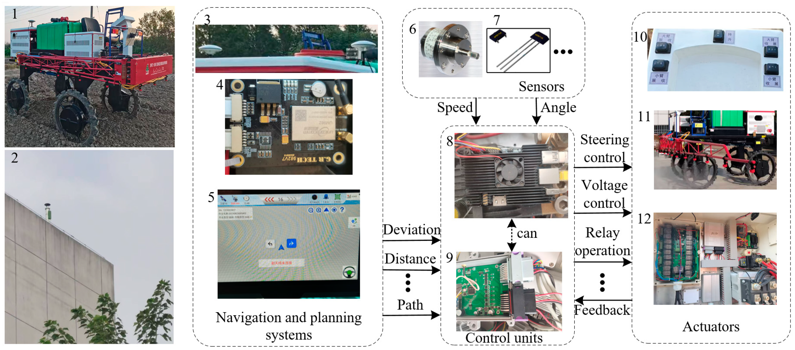
2.1. The Platform of the High-Clearance Sprayer

This study employed an autonomous navigation agricultural machinery platform equipped with a four-wheel independent-drive high-clearance sprayer as the primary research platform. The sprayer system is composed of a frame assembly, a 500 L storage tank, a spray unit, and an electromechanical drive system. The spray unit is equipped with an oil–electric hybrid power system, where a 28.5 kW generator serves as the main power source and a 72 V battery provides energy support. Once the gasoline generator is activated, the sprayer can operate continuously for up to 10 h. A key innovation of this system is the adoption of a four independent-wheel differential steering system, which differs from traditional Kalman steering or four-wheel steering approaches. This system achieves precise control of straight line and turning movements by synchronizing the rotational speeds of the four wheel–motor drives, thereby ensuring stability and reliability during operation. The autonomous navigation system of the high-clearance sprayer includes a navigation positioning system, a path planning system, an embedded control system, and sensor equipment. The overall structure of the high-clearance sprayer system is illustrated in Figure 1, with detailed technical specifications provided in Table 1.
The high-clearance sprayer system achieves autonomous navigation and driving operations by receiving real-time lateral deviation, heading deviation, heading distance, and vehicle speed information. To obtain more precise location and heading information, the GNSS dual-antenna installation baseline is perpendicular to the sprayer’s direction of travel. The RTK system acquires the sprayer’s position information and transmits it via RS232 at a frequency of 10 Hz. Communication between the Linux system controller and the embedded control box is facilitated through the CAN bus at a rate of 500 Kbps. Hall sensors and angle sensors are installed on the sprayer’s wheels and the centers of the steering and rear steering axles, respectively, to collect real-time wheel speed and steering angle information as feedback. Additionally, a patrol instrument is employed to monitor the sprayer’s real-time voltage. The Linux system controller is equipped with Ubuntu and the second-generation Robot Operating System (ROS2). The navigation algorithm node, sprayer node, and upper computer interface node are implemented using computer language. During navigation operations, the upper computer interface node runs on the remote end to monitor the sprayer’s status in real time and publish target path information. The navigation algorithm node then subscribes to various sensor data, processes the information, and publishes control commands. Finally, the sprayer node subscribes to these control commands to execute the navigation tasks.

2.2. The Mathematical Model for the High-Clearance Sprayers

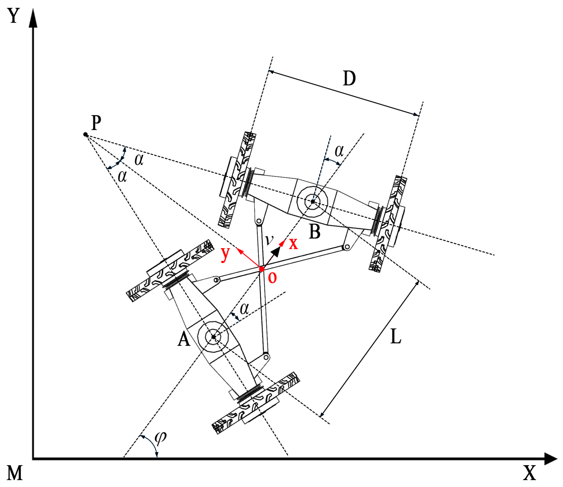
2.2.1. Kinematic Modeling of the Chassis

The high-clearance four-wheel independent electric-driven sprayer features an innovative steering system consisting of the chassis, front, and rear steering axles. Unlike traditional Ackermann or differential steering systems, each axle is connected to the chassis’ steering centers via high-precision bearings. Powered by four independently controlled high-torque hub motors and a motor torque coordination control algorithm, the sprayer achieves straight movement and steering without additional assist devices. A dual-redundancy auxiliary link mechanism, designed through multi-body dynamics modeling, optimizes the steering synchronization and enhances the dynamic stability, improving the anti-interference capability and steering accuracy. Meanwhile, the establishment of a kinematic model is the key step in designing the trajectory tracking algorithm, and the accuracy of the modeling directly affects the tracking performance of the control algorithm. Considering the characteristics of the agricultural machinery working environment, its dynamic properties can be simplified as a kinematic model for processing [4,11,31]. The modeling method based on geometric kinematics principles is reasonable and applicable in such application scenarios. As shown in Figure 2, showing the kinematic model of the agricultural machinery chassis, the high-clearance sprayer used in this study employs a front and rear steering axle mechanical coupling structure, which synchronizes the steering motion through rigid linkages. This mechanism ensures that the front and rear steering axles maintain a defined geometric relationship during the steering process, providing a structural foundation for the kinematic modeling.
The world coordinate frame X M Y and the body-fixed frame x o y are first defined, while points A and B are the center points of the front and rear steering axles, respectively. Let L and D represent the distance between the two steering centers A and B and the length of the steering bridge corresponding to the track width of the same side’s wheels, respectively. Here v ,   α ,   ϕ are the speed, steering wheel angle, and heading angle, respectively. The four wheels of the vehicle are performing a turning motion around point P , with the counterclockwise rotation defined as positive.
In the triangle A B P , the angle bisector P O represents the turning radius of the vehicle. Based on the fundamental knowledge of triangles and the law of sines, the relationship of the turning radius can be expressed as follows:
2 sin α L = sin π 2 α R
In the above equation, R represents the turning radius of the chassis, based on the chassis structure of the vehicle. Therefore, we can derive:
tan α = L 2 R
Based on the geometric principles of kinematics, it can be considered that the rate of change of the vehicle’s direction is equivalent to the vehicle’s angular velocity (denoted as ω ), which is also the yaw angular velocity of the vehicle body, which is given by:
ω = φ · = v R
Therefore, by substituting Equation (2) into Equation (3), the relationship between the vehicle’s steering angle and its rotational speed can be obtained:
φ · = 2 v tan α L
Integrating the above calculations, the kinematic model of the agricultural machinery at the center of mass along the global coordinate can be obtained:
T · = X · Y · φ · = cos φ sin φ 2 tan α / L × v
In the aforementioned equations, T = X Y ϕ T represents the pose of the high-clearance sprayer in the world coordinate system.

2.2.2. Pure Pursuit Strategy Applied to the Chassis

The pure pursuit algorithm is a geometric tracking control method. Its core idea is to calculate the steering command by establishing a geometric constraint relationship between the vehicle’s current centroid and a look-ahead point on the reference path. The algorithm first selects a look-ahead point at a fixed distance ahead of the vehicle on the reference path as the tracking target. Then, based on the geometric relationship between the position of the look-ahead point, the steering radius, and the vehicle’s heading angle, the optimal steering angle is calculated in real time. For the high-clearance sprayer studied in this paper, its front and rear steering axles are mechanically coupled through auxiliary linkages to ensure synchronization of the front and rear steering angles. This symmetric steering characteristic allows the four-wheel vehicle model to be equivalently simplified to a two-wheel bicycle model [33]. Therefore, its path tracking schematic is shown in Figure 3 and the meanings of the symbols are as shown in Table 2.
From Figure 3, based on the fundamental knowledge of the sine rule in triangles, we can derive the following:
R = l d 2 sin α
Based on the vehicle kinematics model, it is known that δ = δ f = δ r ; therefore:
δ = arctan L 2 R
Combining the above, according to the coordinate relationship expression in the target path tracking process and the Pythagorean theorem, we can obtain:
k = 1 R = 2 x i 2 l d 2
As illustrated in Figure 3, the geometric relationship between the abscissa of the target point on the reference path and the vehicle’s lateral tracking error can be derived as follows:
x i = e y cos φ l d 2 e y 2 sin φ
By combining Equations (7)–(10), the steering angle formula for the vehicle’s front wheels can be obtained as follows:
δ = arctan 2 L e y cos φ l d 2 e y 2 sin φ / l d 2
The analytical expression in Equation (10), combined with the navigation and planning system of the high-clearance sprayer, indicates that the chassis’ lateral error e y and heading error θ are obtained in real time via the RTK-GNSS positioning module. Consequently, the look-ahead distance l d remains the sole parameter requiring optimization during the agricultural vehicle’s path tracking control process. In the research presented in this paper, the high-clearance field sprayer has two control inputs—one is the steering angle of the vehicle’s front wheels δ and the other is the vehicle’s linear velocity v . The former is the main control input affecting the lateral movement of the sprayer; hence, the trajectory tracking controller is designed to obtain the appropriate front wheel steering angle δ .
Our analysis based on the established path tracking control model shows that when the look-ahead distance l d is large, the agricultural machinery will converge to the target trajectory with a smaller path curvature k , although this introduces two issues: (1) the steering action is triggered too early, leading to a decrease in real-time trajectory tracking performance; (2) the system’s dynamic response speed is reduced. On the other hand, when l d is small, although the machinery can quickly approach the target trajectory with a larger curvature k , this induces underdamped dynamic characteristics, specifically manifested as (1) significant overshoot oscillations in the control system and (2) a noticeable deterioration in the trajectory tracking stability [34]. In conclusion, the proper adjustment of the look-ahead distance l d is critical for the accuracy and reliability of the pure pursuit algorithm in path tracking. Thus, the optimization of the look-ahead distance l d is a decisive factor in ensuring the reliability of the pure pursuit algorithm for path tracking. In the autonomous navigation of high-clearance sprayers, selecting the right look-ahead distance is crucial for the path tracking performance. However, due to the complexity of farmland environments and their varying conditions, determining this parameter requires extensive field trials for calibration, making it a key optimization challenge for the sprayer’s navigation system.

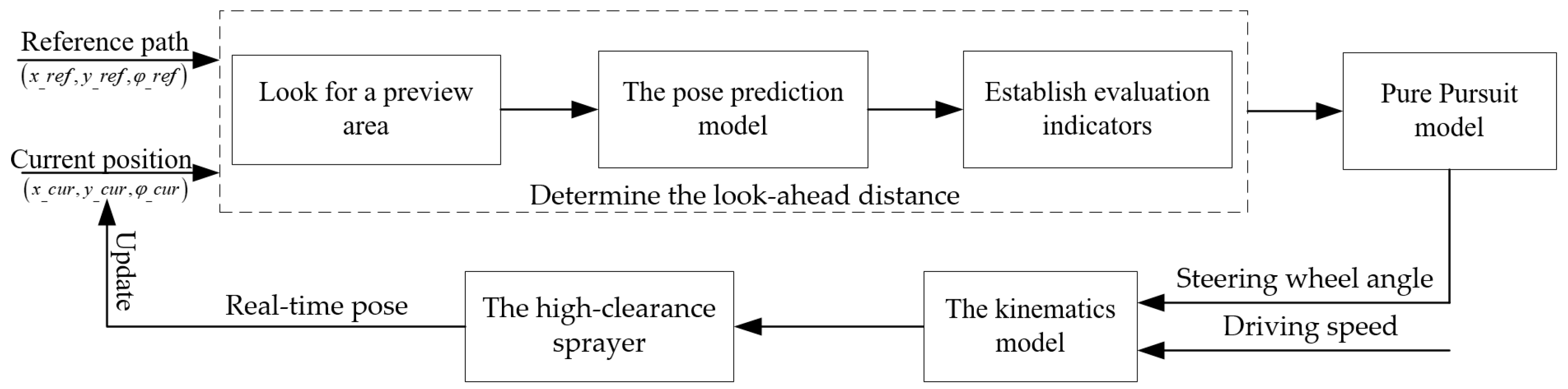
2.3. Path Tracking Strategy Based on Self-Adjusting Look-Ahead Distance

In this part, we introduce the path tracking strategy intended for the automated navigation system of the high-clearance sprayer, which is discussed in detail, with its technical framework shown in Figure 4. First, the look-ahead area range for path tracking is determined based on the spatial relationship between the current position of the high-clearance sprayer and the reference path. Next, by utilizing the tracked chassis posture prediction model, the path points within the look-ahead region are examined, and the tracking error for each point is computed. Subsequently, evaluation metrics for the tracking error are established, allowing for the adaptive selection of the look-ahead distance parameter in the pure tracking algorithm model. This process leads to the determination of the steering wheel angle variable for the motion control of the high-clearance sprayer, ensuring that the agricultural machinery can autonomously and accurately follow the target path.

2.3.1. Look for the Preview Area

This paper studies the application of the self-adjusting look-ahead distance-based path tracking algorithm in the automatic navigation system of high-clearance sprayers. Before adaptively selecting the self-adjusting look-ahead distance, it is essential to first identify the dynamic range of the look-ahead distance, referred to as the preview area. When tracking the reference operational path, the range represented by the preview area is determined by the current position of the agricultural machinery and is updated as the position of the agricultural machinery is updated. The description of the preview area is shown in Figure 5.
In Figure 5, l d min and l d max are the minimum look-ahead distance and the maximum look-ahead distance, respectively; G 1 , G 2 , and G 3 refer to the points on the reference path that are closest to the high-clearance sprayer, the reference path point corresponding to the minimum look-ahead distance, and the reference path point corresponding to the maximum look-ahead distance, respectively; x , y is the current position of the agricultural machinery; x i , y i represents the coordinates of the path point. The value of the look-ahead distance for the path tracking algorithm with the self-adjusting look-ahead distance should meet a certain range of variation. The connections between all the path points within the preview zone and the current location of the agricultural machinery can be represented according to Equation (11):
l d min ( x i x ) 2 + ( y i y ) 2 l d max
The above equation defines the mathematical representation of the preview area. According to previous research [35,36], it has been established that when the starting point of the path is known and the length of the tracked path is fixed, the change in coordinates between the path’s endpoint and the current position of the agricultural machinery does not have any effect on the total path length. Therefore, in this study, the tracking path length corresponding to the preview area is equivalently integrated into a single path length variable denoted by l , and its mathematical expression is as follows:
l = ( x i + 1 x i ) 2 + ( y i + 1 y i ) 2 d G 2 G 3
Based on the previous analysis and the schematic representation of the look-ahead area for high-clearance sprayers, the following steps are suggested to determine the range of the look-ahead area. Initially, begin at the closest point between the agricultural machinery and the reference path, then compare this with the predefined minimum look-ahead distance parameter. Based on the comparison results, determine whether the starting point of the look-ahead area is G 1 or G 2 . Next, begin at the chosen point and perform an integration process along the reference path to compute the accumulated integral length, continuing until one of the following conditions is satisfied: (1) the integral length surpasses the maximum allowable length l max ; or (2) the distance from the current position to the path point exceeds the maximum look-ahead distance l d max . Simultaneously, the point on the reference path that satisfies the condition should be located at a distance from the current position of the agricultural machinery that is greater than or equal to the maximal look-ahead distance. Once the search concludes, the endpoint of the preview area is identified, and its coordinates are considered as G 3 . By following this procedure, a series of coordinates for points along the reference path, from the starting point to the endpoint of the preview area, will be generated, thereby outlining the boundaries of the look-ahead region.

2.3.2. The Model for Predicting the Pose

During the autonomous navigation and trajectory tracking process of agricultural machinery, under ideal conditions, the position of the agricultural machinery is updated at a fixed frequency. We can assume that the position update frequency of the high-clearance sprayer is 1 / Δ t , where Δ t is the time interval for updating. The position update of the high-clearance sprayer is based on the steering wheel angle as the input control variable, and the value of the position description variable is determined by the component of the velocity variable. Therefore, after a time interval of Δ t , the position update of the agricultural machinery can be obtained through integration over time.
x t + Δ t = x t + t t + Δ t v cos φ d t y t + Δ t = y t + t t + Δ t v sin φ d t φ t + Δ t = φ t + t t + Δ t v tan δ / L d t
The current location is characterized by the coordinates x ( t ) , y ( t ) , ϕ ( t ) , and the predicted pose of the high-clearance sprayer anticipated after the time duration of Δ t is represented by x ( t + Δ t ) , y ( t + Δ t ) , ϕ ( t + Δ t ) .
The prompt updating of the agricultural machinery’s position data justifies the assumption that the machinery’s speed and the steering angle are stable during the time frame of Δ t . The integral equation mentioned above can be approximated as:
x t + Δ t = x t + v × cos φ × Δ t y t + Δ t = y t + v × sin φ × Δ t φ t + Δ t = φ t + v × tan δ / L × Δ t
The equations outlined earlier develop a model for predicting the position of agricultural machinery, capable of estimating where the equipment is expected to be after a brief time period Δ t . This model takes into account the present condition of the agricultural machinery, such as its velocity, orientation, and possible external factors, and forecasts its continuous positional variations over time by simplifying integral equations. Based on this model, a certain front wheel steering angle can be input to achieve an approximate prediction of the agricultural equipment’s operating position. When the model has determined the equipment’s position at a future time point, we can compare this predicted position with the target path and calculate the deviation between the predicted path and the target path to make adjustments to the agricultural equipment, ensuring it follows the predetermined trajectory.

2.3.3. Establishment of Error Evaluation

In the autonomous navigation of a high-clearance sprayer, to maintain optimal path tracking performance at all positions, it is essential to dynamically adjust the look-ahead distance for the pure tracking algorithm based on the changes in the current position between the tracked chassis and the trajectory. In this research, the look-ahead distance can be calculated based on the chosen target point. As a result, by evaluating all the path points within the look-ahead zone as potential target points, the predicted position after following each target point is determined. Next, the total discrepancy between the predicted position of the tracked chassis and the reference trajectory is measured, encompassing both lateral and heading errors. By developing error assessment criteria, the target point that optimizes the evaluation metric is found, thereby determining the appropriate look-ahead distance value. By leveraging the target point set in the look-ahead zone alongside the chassis position prediction model, we formulate the comprehensive path tracking error metric mathematically.
J i = β e y i 2 + λ e φ i 2
In Equation (16), e y i and e ϕ i respectively represent the lateral and heading errors that correspond to the goal point placed on the reference path traversed based on the prediction model at the current position of the high-clearance sprayer; β and λ are the weight coefficients of the errors, with β + λ = 1 . In summary, the error evaluation function is established as follows:
F i = β + λ / J i
By designing the error evaluation function for the target point within the look-ahead area, a complete system for evaluating path tracking errors based on the position prediction model is established. Each target point in the look-ahead region corresponds to an evaluation value. By substituting all target path points into the evaluation function, the maximum value can be extracted from the evaluation value set, which is then used as the optimal metric for a path tracking error evaluation. Through this method, the look-ahead distance of the high-clearance sprayer is flexibly modified based on real-time error feedback during path tracking, thereby accomplishing the desired goal of optimal autonomous navigation and motion control via adaptive look-ahead regulation according to the pure pursuit algorithm.

3. Results and Discussion

3.1. Model-Based Simulation Verification

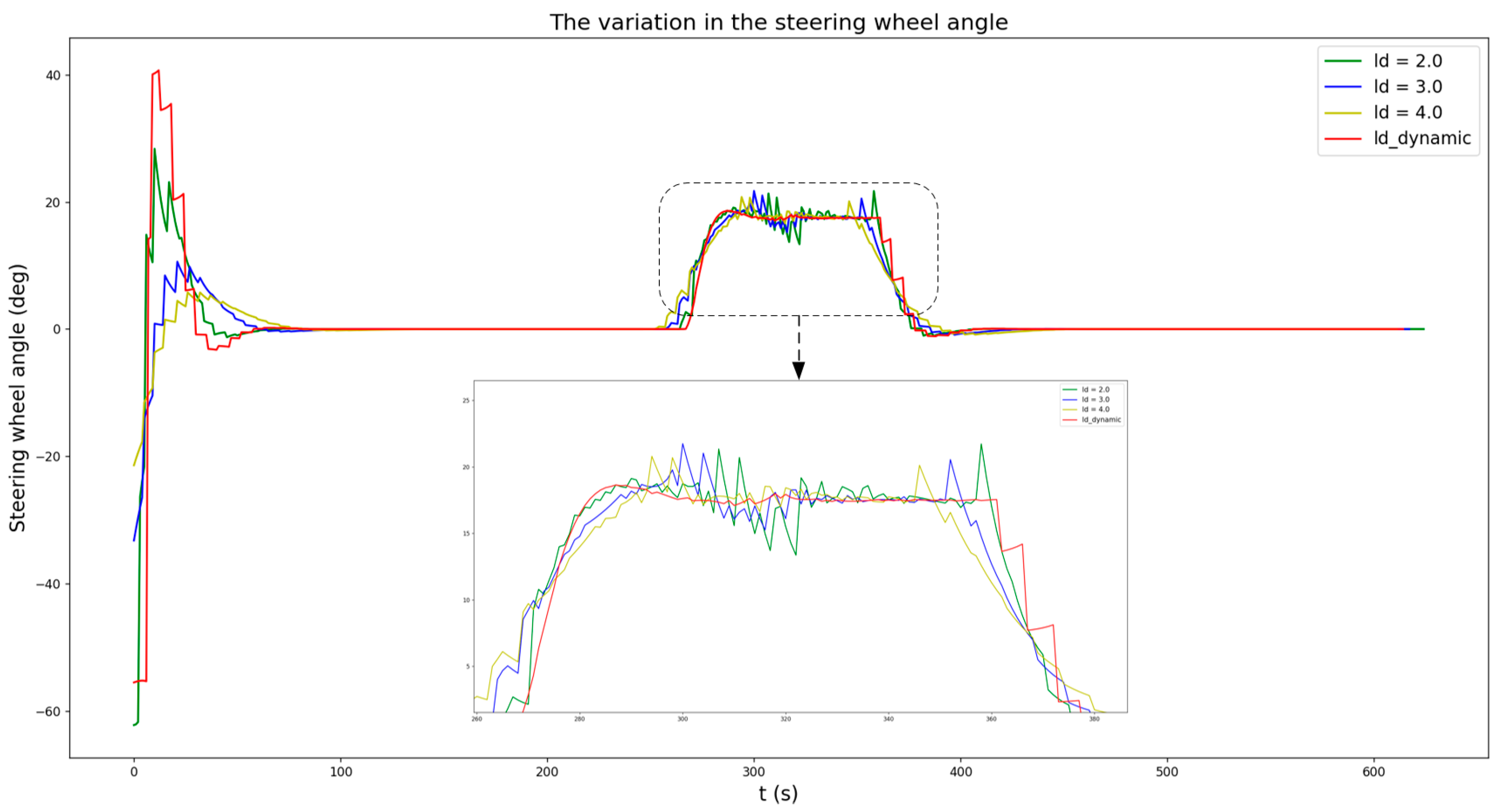
3.1.1. Algorithm Simulation Test

During the operation of agricultural machinery, various types of machinery follow distinct operational pathways, depending on the specific performance parameters of the machinery and the conditions of the field. Since high-clearance sprayers need to travel within the field during spraying operations to achieve full coverage of the field area and meet the corresponding work requirements, they adopt a back-and-forth operational method with forward and backward movements and adjacent working trips. This method supports the accurate alignment of agricultural machinery, helping to minimize redundant and overlooked work.
Based on the characteristics of field operation path planning for high-clearance sprayers, their motion trajectories primarily consist of straight segments and curved segments. To validate the performance of the path tracking algorithm in the automatic navigation system, we constructed a U-shaped test path (curvature radius of 6 m) using a single-cycle operational route for simulation and testing. The key experimental parameters were configured according to the mechanical specifications of this equipment: (1) U-path curvature radius: 6 m; (2) traveling speed: 2 m/s; (3) initial tracking point: 2 m lateral offset from the reference path origin.
In the simulations by MATLAB (R2023b) environment, fixed look-ahead distances (2.0 m, 2.5 m, 3.0 m) served as the control group for benchmark testing against the self-adjusting look-ahead distance pure pursuit algorithm. The tracking trajectories and partially enlarged diagrams are presented in Figure 6.

3.1.2. Analysis of the Algorithm Simulation

Through the simulation test of the pure tracking algorithms for fixed and self-adjusting look-ahead distances, we selected the first 600 sets of agricultural machinery positions, and recorded and statistically analyzed the lateral error data generated during the U-shaped trajectory tracking in the simulation test process, as shown in Table 3 and Table 4. From the data in these two tables, it can be clearly seen that the pure pursuit algorithm based on the self-adjusting look-ahead distance generally produces a smaller lateral error during the path tracking process compared to the algorithm based on a fixed look-ahead distance, especially at the curves where the lateral error is most pronounced. This is primarily due to the fact that the pure tracking algorithm, utilizing the self-adjusting look-ahead distance, continuously adjusts the look-ahead distance in real time during the autonomous navigation process, based on the characteristics of the reference path, thereby effectively accommodating variations in path curvature. This allows the agricultural machinery to track the path target points with the optimal look-ahead distance, reducing the deviation from the reference trajectory during the path tracking process.
Additionally, it is crucial for path tracking to maintain driving stability, with the steering wheel angle avoiding excessive oscillations. As illustrated in Figure 7, the self-adjusting look-ahead distance-based tracking algorithm presented in this study yields smoother and more stable steering wheel steering angles at curve turns, with minimal oscillation. In contrast, the tracking algorithm using a fixed look-ahead distance tends to exhibit more pronounced oscillations in the steering wheel steering angles during curve transitions.

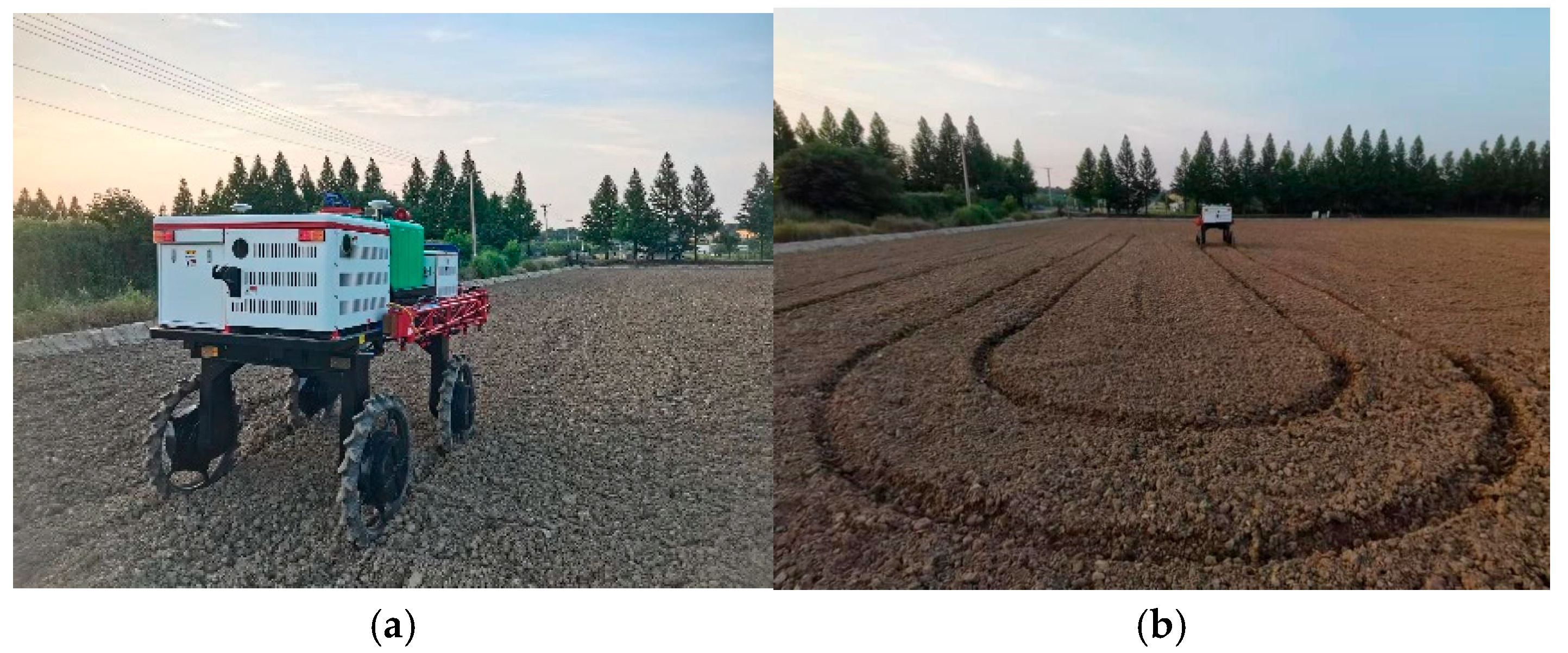
3.2. Path Tracking Tests in the Field

To further verify the effectiveness and reliability of the path tracking algorithm applied to the autonomous navigation system of the high-clearance sprayer proposed in this paper, field experiments for the autonomous navigation of the agricultural machine were conducted in standardized farmland.

3.2.1. The Experimental Site of the Field Trials

The experimental site was located in a field awaiting work, and its geographical coordinates were approximately 119.5005959° E longitude and 31.2155542° N latitude. In the field experiment, the high-clearance plant protection sprayer followed the preset reference path using the path tracking algorithm, and the machine’s position information was obtained in real-time using BeiDou navigation equipment. According to the path planning requirements of the round-trip operation method, the reference path for the experiment was designed in a U-shape, consisting of two straight segments and a semicircle with a radius of 6 m. This parameter design (straight segment length of 54 m and semicircle radius of 6 m) takes into account both the performance parameters of the agricultural machine and the actual operating conditions of the farmland. The experimental site is shown in Figure 8.

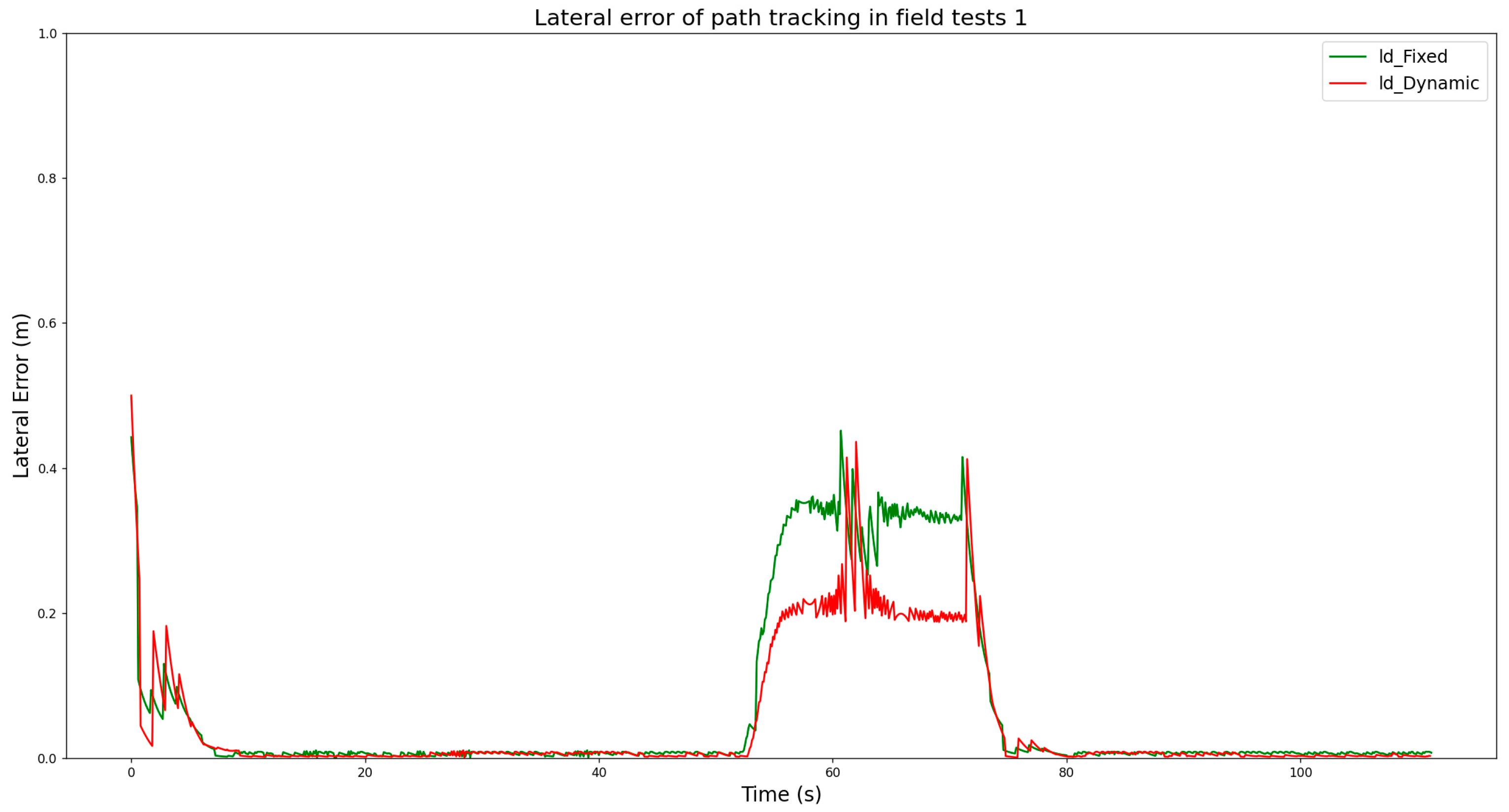
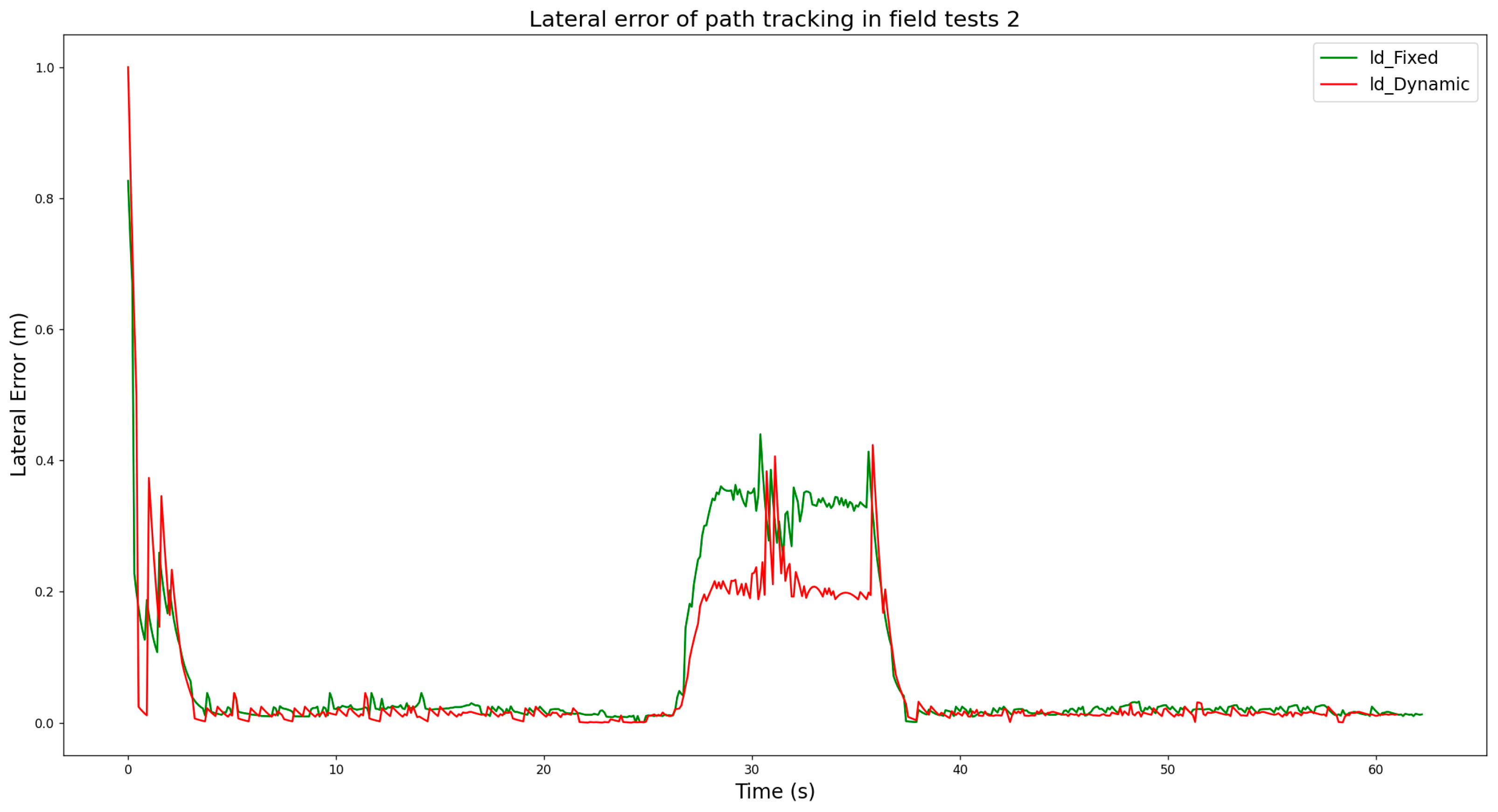
3.2.2. The Analysis and Results of the Field Tests

Under the same test path conditions, considering different initial positions and driving speeds, comparative experiments on path tracking were conducted for two types of pure tracking algorithms with fixed and self-adjusting look-ahead distances. According to the analysis from the simulation experiments, when the look-ahead distance is fixed at 2.0 m, the path tracking results and error data for both algorithms are very close, exhibiting strong comparability in testing. Therefore, ensuring the tracking performance and real-time responsiveness, an initial fixed look-ahead distance of 2.0 m was set in comparison with the dynamic planning look-ahead distance for path tracking strategies, and multiple comparative experiments were conducted. The lateral error data of the agricultural machinery during each path tracking completion were recorded, and statistical and analytical work was carried out.
In field test 1, the agricultural machinery was initially positioned 0.5 m from the starting point of the path with a speed of 1.0 m per second. The experiment recorded the lateral errors of two path following algorithms, as shown in Figure 9 and detailed in Table 5. While the lateral error trends for both algorithms during the path following process were similar, there was a significant difference in lateral errors during the curved path segment. Specifically, for the self-adjusting look-ahead pure pursuit algorithm, the average lateral error on the curved path was 0.143 m, with a maximum error of 0.436 m and a variance of 0.11 square meters. For the fixed look-ahead pure pursuit algorithm, the average lateral error on the curved path was 0.212 m, with a maximum error of 0.452 m and a variance of 0.21 square meters. These results indicate that the self-adjusting look-ahead algorithm generally has smaller lateral error values. It is also noted that the time sequence in which the self-adjusting look-ahead and fixed look-ahead algorithms enter the steering process differs on the curved path, which directly accounts for the observed differences in lateral errors between the two algorithms.
In field test 2, the agricultural machinery’s initial position was set 1.0 m away from the path trajectory’s starting point, with an increased speed of 2.0 m/s. The lateral errors of the two path tracking algorithms were recorded and are shown in Figure 10 and Table 6. It was observed that changing the experimental parameters did not affect the consistency of the path tracking performance of either algorithm. The initial distance increase only altered the starting operational state of the machinery’s path tracking without impacting the overall process. An increase in the machinery’s operational speed also ensured good stability in path tracking. The data from the table indicate that the pure pursuit algorithm with the self-adjusting look-ahead distance had an average lateral error of 0.137 m; meanwhile, the pure pursuit algorithm using a fixed look-ahead distance exhibited an average lateral error of 0.198 m. A comparative analysis of the lateral tracking error data on curved path segments revealed that the pure pursuit algorithm based on self-adjusting look-ahead distance resulted in smaller errors than the one with a fixed look-ahead distance. The field tests confirmed that the algorithm introduced in this paper can track the reference path accurately and smoothly, demonstrating a significant improvement over the pure pursuit algorithm with a fixed look-ahead distance.

4. Conclusions

This paper tackles the precision challenges and look-ahead distance parameter tuning issues in pure pursuit algorithms for the autonomous path tracking navigation of agricultural machinery. A self-adjusting look-ahead distance pure pursuit algorithm is proposed, which is founded on a pure pursuit algorithm model that incorporates agricultural machinery kinematics. By designing a weight coefficient for tracking errors and introducing a comprehensive error evaluation function, the algorithm predicts the forthcoming path tracking position and error based on the real-time status within the look-ahead zone. It then utilizes the evaluation function to find the optimal look-ahead distance that corresponds to the best machine posture, serving as a crucial parameter for path tracking. This approach aims to achieve a dynamically adaptive look-ahead distance for the pure pursuit of agricultural machinery paths.
We conducted simulation and field tests for the pure pursuit algorithm, specifically adapted for the characteristics of high-clearance plant protection machinery in field operations, in accordance with the proposed path tracking algorithm. By comparing pure tracking algorithms with fixed and self-adjusting look-ahead distances, we validated the proposed algorithm’s stable and dependable tracking capabilities. It excels particularly on curved paths with notable tracking errors, showing a pronounced advantage in error comparison metrics and smoother steering wheel steering angle variations, which significantly enhance the accuracy of the agricultural machinery path tracking. Furthermore, the algorithm streamlines the calibration process for the look-ahead distance parameter, offering substantial benefits for the swift application and deployment of pure pursuit algorithms in autonomous navigation and motion control for agricultural machinery.
The current research mainly focused on relatively ideal working environments. Future studies should conduct more tests and validation experiments under practical conditions, especially in complex terrains and real-world scenarios, to verify the practicality and reliability of the algorithm. At the same time, agronomy serves as the theoretical foundation for agricultural machinery operations. In the future, agricultural machinery navigation control will place a greater emphasis on integrated agronomy. The design of control models must fully consider the characteristics of agricultural work environments and task complexities, further promoting the coordinated development of agricultural machinery and agronomy. Currently, the algorithm models used in agricultural machinery autonomous navigation path tracking controllers do not fully account for certain dynamic characteristics of motion. To this end, our upcoming work will seek to resolve the limitations in current agricultural machinery models and control techniques, implementing high-precision dynamic modeling and autonomous navigation for optimized operational precision and efficiency.

Author Contributions

Conceptualization, X.W. and B.Z.; methodology, X.W.; software, X.W.; validation, X.W., X.D. and H.C.; formal analysis, X.W.; investigation, X.D.; resources, T.Z.; data curation, B.Z.; writing—original draft preparation, X.W.; writing—review and editing, X.W.; visualization, X.W.; supervision, C.W.; project administration, C.W.; funding acquisition, C.W. All authors have read and agreed to the published version of the manuscript.

Funding

This research was funded by the Priority Academic Program Development of Jiangsu Higher Education Institutions (PAPD-2023-87), the Key and General Projects of Jiangsu Province (No. BE2022338), the Postgraduate Research and Practice Innovation Program of Jiangsu Province (No. KYCX24_3990), the Project of the Faculty of Agricultural Engineering of Jiangsu University (No. NZXB20200102), Jiangsu Province Modern Agricultural Machinery Equipment Technology Promotion Project (No. NJ2024-09).

Data Availability Statement

The data provided in this study can be obtained upon request from the corresponding author.

Conflicts of Interest

The authors have no conflicts of interest to disclose.

References

  1. Shen, Y.; Zhang, Y.; Liu, H. Review of Automatic Control Technology for Agricultural Equipment. Trans. Chin. Soc. Agric. Eng. 2023, 54, 1–18. [Google Scholar]
  2. Zhang, M.; Ji, Y.; Li, S. Research progress of agricultural machinery navigation technology. Trans. Chinese Soc. Agric. Eng. 2020, 51, 1–18. [Google Scholar]
  3. Li, H.; Chen, L.; Zhang, Z. A Study on the Utilization Rate and Influencing Factors of Small Agricultural Machinery: Evidence from 10 Hilly and Mountainous Provinces in China. Agriculture 2023, 13, 51. [Google Scholar] [CrossRef]
  4. Li, C.; Wu, J.; Pan, X.; Dou, H.; Zhao, X.; Yang, S.; Zhai, C. Design and Experiment of a Breakpoint Continuous Spraying System for Automatic-Guidance Boom Sprayers. Agriculture 2023, 27, 13. [Google Scholar] [CrossRef]
  5. Jin, Y.; Liu, J.; Xu, Z. Development status and trend of agricultural robot technology. Int. J. Agric. Biol. Eng. 2021, 14, 1–19. [Google Scholar] [CrossRef]
  6. Chao, S. Current Status and Development Trends of Agricultural Plant Protection Mechanization. Agric. Equip. Technol. 2020, 46, 7–8. [Google Scholar]
  7. Liu, Z.; Zhang, Z.; Luo, X.; Wang, H.; Huang, P. Design of automatic navigation operation system for Lovol ZP9500 high clearance boom sprayer based on GNSS. Trans. Chin. Soc. Agric. Eng. 2018, 34, 15–21. [Google Scholar]
  8. Jing, L.; Zhang, Y.; Shen, Y.; He, S.; Liu, H. Adaptive Trajectory Tracking Control of 4WID High Clearance Unmanned Sprayer. Trans. Chin. Soc. Agric. Eng. 2021, 52, 408–416. [Google Scholar]
  9. Zhang, C.; Gao, G.; Zhao, C.; Li, L.; Li, C.; Chen, X. Research on 4WS agricultural machine path tracking algorithm based on fuzzy control pure tracking model. Machines 2022, 10, 597. [Google Scholar] [CrossRef]
  10. Shen, Y.; He, S.; Liu, H.; Cui, Y. Design and experiment of self-steering electric chassis structure of high clearance sprayer. Trans. Chin. Soc. Agric. Eng. 2020, 51, 385–392, 402. [Google Scholar]
  11. Cui, B.; Cui, X.; Wei, X.; Zhu, Y.; Ma, Z.; Zhao, Y.; Liu, Y. Design and Testing of a Tractor Automatic Navigation System Based on Dynamic Path Search and a Fuzzy Stanley Model. Agriculture 2024, 14, 2136. [Google Scholar] [CrossRef]
  12. Chai, X.; Hu, J.; Ma, T.; Liu, P.; Shi, M.; Zhu, L.; Zhang, M.; Xu, L. Construction and Characteristic Analysis of Dynamic Stress Coupling Simulation Models for the Attitude-Adjustable Chassis of a Combine Harvester. Agronomy 2024, 14, 1874. [Google Scholar] [CrossRef]
  13. Li, J.; Shang, Z.; Li, R.; Cui, B. Adaptive Sliding Mode Path Tracking Control of Unmanned Rice Transplanter. Agriculture 2022, 12, 1225. [Google Scholar] [CrossRef]
  14. Kong, F.; Qiu, B.; Dong, X.; Yi, K.; Wang, Q.; Jiang, C.; Zhang, X.; Huang, X. Design and Development of a Side Spray Devicefor UAVs to Improve Spray Coverage in Obstacle Neighborhoods. Agronomy 2024, 14, 2002. [Google Scholar] [CrossRef]
  15. Li, Z.Q.; Chen, L.Q.; Zheng, Q.; Dou, X.Y.; Yang, L. Control of a path-following caterpillar robot based on a sliding mode variable structure algorithm. Biosyst. Eng. 2019, 186, 293–306. [Google Scholar] [CrossRef]
  16. Wang, H.; Wang, G.; Luo, X.; Zhang, Z.; Gao, Y.; He, J.; Yue, B. Control method of agricultural machinery navigation path tracking based on pre-aiming tracking model. Trans. CSAE 2019, 35, 11–19. [Google Scholar]
  17. Cui, B.; Sun, Y.; Ji, F.; Wei, X.; Zhu, Y.; Zhang, S. Study on whole field path tracking of agricultural machinery based on fuzzy Stanley model. Trans. CSAM 2022, 53, 43–48, 88. [Google Scholar]
  18. Heredia, G.; Ollero, A. Stability of autonomous vehicle path tracking with pure delays in the control loop. Adv. Rob. 2007, 21, 23–50. [Google Scholar] [CrossRef]
  19. Liu, W.; Zhou, J.; Liu, Y.; Zhang, T.; Yan, M.; Chen, J.; Zhou, C.; Hu, J.; Chen, X. An Ultrasonic Ridge-Tracking Method Based on Limiter Sliding Window Filter and Fuzzy Pure Pursuit Control for Ridge Transplanter. Agriculture 2024, 14, 1713. [Google Scholar] [CrossRef]
  20. Iida, M.; Uchida, T.; Ishibashi, Y.; Saito, K.; Suguri, S.; Masuda, K. Path-following control of a head-feeding combine robot. Eng. Agric. Environ. Food 2013, 6, 61–68. [Google Scholar] [CrossRef]
  21. Kurita, H.; Iida, M.; Cho, W.; Suguri, M. Rice autonomous harvesting: Operation framework. J. Field Rob. 2017, 34, 1084–1099. [Google Scholar] [CrossRef]
  22. Lu, E.; Xue, J.; Chen, T.; Jiang, S. Robust Trajectory Tracking Control of an Autonomous Tractor-Trailer Considering Model Parameter Uncertainties and Disturbances. Agriculture 2023, 13, 869. [Google Scholar] [CrossRef]
  23. Li, G.; Ma, X.; Li, Y. Adaptive sliding mode control based on time-delay estimation for underactuated 7-DOF tower cranes. IEEE Trans. Syst. Man Cybern. Syst. 2025; early access. [Google Scholar]
  24. Li, G.; Ma, X.; Li, Y. Robust command shaped vibration control for stacker crane subject to parameter uncertainties and external disturbances. IEEE Trans. Ind. Electron. 2024, 71, 14740–14752. [Google Scholar] [CrossRef]
  25. Huang, Y.; Tian, Z.; Jiang, Q.; Xu, J. Path tracking based on improved pure pursuit model and PID. In Proceedings of the 2020 IEEE 2nd International Conference on Civil Aviation Safety and Information Technology (ICCASIT), Chengdu, China, 14–16 October 2020; pp. 359–364. [Google Scholar]
  26. Macenski, S.; Singh, S.; Martin, F.; Ginés, J. Regulated pure pursuit for robot path tracking. Auton. Robot. 2023, 47, 685–694. [Google Scholar] [CrossRef]
  27. Choi, W.Y.; Chung, C.C. Optimizing look-ahead distance for vehicle lateral control: A controller-adaptive approach. IEEE Trans. Intell. Veh. 2024, 4, 1–12. [Google Scholar] [CrossRef]
  28. Kamal, M.A.S.; Bakibillah, A.S.M.; Hayakawa, T.; Yamada, K. Cooperative look-ahead lane change system for improving driving intelligence of automated vehicles in critical scenarios. IEEE Trans. Intell. Veh. 2024, 9, 5876–5888. [Google Scholar] [CrossRef]
  29. Zhang, S.; Wei, X.; Liu, C.; Ge, J.; Cui, X.; Wang, F.; Wang, A.; Chen, W.-M. Adaptive path tracking and control system for unmanned crawler harvesters in paddy fields. Comput. Electron. Agric. 2024, 210, 109878. [Google Scholar] [CrossRef]
  30. Li, G.; Wang, Y.; Guo, L.; Tong, J. Improved pure pursuit algorithm for rice transplanter path tracking. Trans. CSAM 2018, 49, 21–26. [Google Scholar]
  31. Yang, Y.; Liu, Y.; Wang, Y.; Zhang, G.; Cui, X.; Qiao, Y.; Xie, C. An optimal goal point determination algorithm for automatic navigation of agricultural machinery: Improving the tracking accuracy of the Pure Pursuit algorithm. Comput. Electron. Agric. 2022, 196, 106760. [Google Scholar] [CrossRef]
  32. Fu, X.; Han, Z.; Han, K.; Feng, X.; Huang, T. Improved pure pursuit algorithm for path tracking of wheeled harvesters based on particle swarm optimization. J. Agric. Eng. Res. 2023, 27, 1–10. [Google Scholar]
  33. Zhang, H.Q.; Wang, G.D.; Lv, Y.F.; Qi, C.L.; Liu, L.; Gong, J.L. Research on agricultural machinery path tracking algorithm based on improved pure pursuit model. Trans. CSAM 2020, 51, 18–25. [Google Scholar]
  34. MathWorks. (n.d.). Pure Pursuit Controller—MATLAB & Simulink. MathWorks Documentation. Available online: https://de.mathworks.com/help/robotics/ug/pure-pursuit-controller.html (accessed on 21 May 2025).
  35. Yang, H.; Huang, J.; Li, P.; Han, Z.H. Driver Model Based on Path Preview. Automob. Technol. 2019, 2, 7–13. [Google Scholar]
  36. Luo, Y.; Wei, L.; Xu, L.; Zhang, Q. Stereo-vision-based multi-crop harvesting edge detection for precise automatic steering of combine harvester. Biosyst. Eng. 2022, 215, 115–128. [Google Scholar] [CrossRef]
Figure 1. System composition of the automatic operation high-clearance sprayer: 1. high-clearance sprayer; 2. RTK station; 3. GNSS antenna; 4. UM982; 5. display module; 6. encoder; 7. hall element; 8. Linux system controller; 9. embedded control box; 10. operation panel; 11. spraying equipment; 12. integrated control cabinet.
Agronomy 15 01433 g001
Figure 2. Kinematic model of the chassis for the high-clearance sprayer.
Agronomy 15 01433 g002
Figure 3. Pure pursuit model diagram of the high-clearance sprayer.
Agronomy 15 01433 g003
Figure 4. Path tracking framework of high-clearance sprayer.
Agronomy 15 01433 g004
Figure 5. Schematic diagram of the preview area.
Agronomy 15 01433 g005
Figure 6. Simulation test diagram of the U-path tracking trajectory.
Agronomy 15 01433 g006
Figure 7. Variation of steering wheel angles in U-path tracking.
Agronomy 15 01433 g007
Figure 8. The experimental site (119.5005959° E, 31.2155542° N): (a) the test site and agricultural machinery; (b) the actual running path trajectory.
Agronomy 15 01433 g008
Figure 9. The waveform chart illustrates the lateral error values from field test 1.
Agronomy 15 01433 g009
Figure 10. The waveform chart illustrates the lateral error values from field test 2.
Agronomy 15 01433 g010
Table 1. Key specifications of the high-clearance sprayer.
ParametersUnitValue
Overall sizemm3080 × 11,200 × 2400
Weightkg1680
Wheelbasemm1680
Track widthmm2200
Ground clearancem1.1
Maximum steering angle°−40~40
Minimum turning radiusm1.2
Speedm/s0.4~2
Table 2. Symbolic meanings.
SymbolMeaning
RInstantaneous steering radius
ACenter point of front axle
BCenter point of rear axle
OTurning center of the high-clearance sprayer
GTracking waypoints along the path
PInstantaneous center of rotation
LWheelbase of the high-clearance sprayer
α Angle between the direction to the target point
δ The steering angle of the high-clearance sprayer
k Turning curvature of the high-clearance sprayer
e y Lateral error based on the current position
φ Heading angle based on the current position
l d Look-ahead distance
Table 3. The results of the lateral error during U-path trajectory tracking.
Look-Ahead DistanceThe Average Value of Lateral Error (m)Variance (m)
ld = 2.0 m0.0750.033
ld = 3.0 m0.1500.076
ld = 4.0 m0.2560.214
ld_dynamic0.0720.031
Table 4. The results of the lateral error in U-path turning.
Look-Ahead DistanceThe Average Value of Lateral Error (m)The Max Lateral Error (m)
ld = 2.0 m0.2110.419
ld = 3.0 m0.4760.945
ld = 4.0 m0.8471.599
ld_dynamic0.1450.417
Table 5. Lateral error values in field test 1.
Ref PathPath Tracking AlgorithmAverage Value of Lateral Error (m)Maximum
Lateral Error (m)
Variance (m)
Curve lineFixed
look-ahead
0.2120.4520.021
Dynamic
look-ahead
0.1430.4360.011
Table 6. Lateral error values from field test 2.
Ref PathPath Tracking AlgorithmAverage Value of Lateral Error (m)Maximum
Lateral Error (m)
Variance (m)
Curve lineFixed
look-ahead
0.1980.4390.023
Dynamic
look-ahead
0.1370.4230.011
Disclaimer/Publisher’s Note: The statements, opinions and data contained in all publications are solely those of the individual author(s) and contributor(s) and not of MDPI and/or the editor(s). MDPI and/or the editor(s) disclaim responsibility for any injury to people or property resulting from any ideas, methods, instructions or products referred to in the content.

