Article

An Investigation of the Frequency and Duration of a Drive Spoon–Dispersed Water Jet and Its Influence on the Hydraulic Performance of a Large-Volume Irrigation Sprinkler

1
Key Laboratory of Water-Saving Agriculture of Henan Province, Farmland Irrigation Research Institute, Chinese Academy of Agricultural Sciences, Xinxiang 453002, China
2
Research Center of Fluid Machinery Engineering and Technology, Jiangsu University, Zhenjiang 212013, China
*
Author to whom correspondence should be addressed.
Agronomy 2022, 12(9), 2233; https://doi.org/10.3390/agronomy12092233
Submission received: 26 July 2022 / Revised: 14 September 2022 / Accepted: 15 September 2022 / Published: 19 September 2022
(This article belongs to the Special Issue Water Saving in Irrigated Agriculture)

Abstract

:
The frequency and duration of drive spoon–dispersed water jet directly influence the water distribution pattern and, further, affect water distribution uniformity. A mathematical model for calculating the duration was established, and an experiment was carried out to verify the accuracy of the theory by using high-speed photography (HSP) technique. Another important component of the investigation was the influence of frequency and duration on the water distribution pattern and water distribution uniformity. The results showed that the frequency of drive spoon–dispersed water jet increased and the duration time decreased with increased working pressure and decreased distance between counterweight-installed position and rotation axis. The calculated values of the theory were greater than the measured values. Differences between the measured and predicted values decreased with increased working pressure, and the average difference decreased to 2.98% when the working pressure increased to 0.40 MPa. The application rates within 1–13 m improved and increased about 50% by decreasing the distance from 135 mm to 80 mm. The maximum application rates decreased from 10.3 to 9.2 mm h−1, 9.5 to 8.8 mm h−1, and 8.4 to 7.9 mm h−1 with a working pressure of 0.30, 0.35, and 0.40 MPa, respectively. The Christiansen’s uniformity coefficient (CU) values decreased by increasing the distance between the counterweight and the rotation axis. The maximum CU values were obtained at the spacing coefficient of 1.2, 1.2, and 1.1 for 0.30, 0.35, and 0.40 MPa, respectively. By decreasing the distance from 135 mm to 80 mm, the maximum CU values increased from 58.96% to 75.1%, 68.85% to 80.1%, and 72.46% to 82.17% for 0.30, 0.35, and 0.40 MPa, respectively.

1. Introduction

As water resources become more and more scarce, sprinkler irrigation and micro-irrigation are being promoted worldwide to save water in agriculture [1,2,3,4]. As one of the more efficient water-saving irrigation technologies, sprinkler irrigation can save water and labor, increase crop productivity, and improve crop quality [5,6]. Water-use efficiency significantly increased through sprinkler irrigation [7]. The quality of irrigation, as manifested by the maximum water application rate and the water distribution uniformity [8,9], is largely determined by the hydraulic performance of the sprinkler equipment. Large-volume sprinklers are the most widely used rotating sprinklers in agriculture due to their ability to cover large areas; thus, fewer sprinklers and fewer pipes are needed per unit area [10,11,12,13]. During the normal operation of large-volume irrigation sprinklers, the drive spoon can generate horizontal and vertical impact forces from the water jet [14]. On the one hand, the horizontal force causes the sprinkler to rotate, and the vertical impact force causes the drive arm to pivot downward. On the other hand, the water can be dispersed more uniformly when the water jet impacts the drive spoon.
A great deal of research has been conducted on the effects of operating pressure, nozzle diameter, layout form, and weather conditions on hydraulic performance and water distribution uniformity for small- or medium-sized sprinklers [15,16,17,18]. Burt et al. [19] indicated that the most influential factors of heterogeneity in water distribution are operating pressure variation at the hydrant, the sprinkler design, and the sprinkler layout. Zhu et al. [20] conducted a series of experiments to study the effect of sprinkler head geometrical parameters on hydraulic performance for a fluidic sprinkler. Sheikhesmaeili et al. [12] characterized the spray losses and water distribution of the sprinkler irrigation system with a semi-portable big-size sprinkler on semi-arid areas. Ge et al. [21] analyzed a variety of methods to obtain sprinkler radial water distribution and proposed the most feasible method for a large-volume sprinkler used in mobile sprinkler machines. Ge et al. [22] conducted a comparative analysis of water distribution and kinetic energy distribution for two commonly used high-volume sprinklers. Other scholars investigated possibilities for improving sprinkler hydraulic performance by using various mechanical devices to break up the water jet. Kincaid [23] described a method of modifying the water distribution pattern by attached a deflector to the drive arm to intermittently diffuse the water jet for an impact-drive sprinkler. Tarjuelo et al. [24] reported that the shape of the radial water distribution curve was mainly determined by the sprinkler model, the internal design, the spray angle, and the jet breakup mechanism. Silva [25] investigated the influences of different deflector plates on irrigation uniformity, surface runoff, and crop yield. Li et al. [26] used an intermittent water dispersion device to disperse the water jet and investigated the influence of shape, location parameters, and the number of the dispersion teeth on hydraulic performance. A few scholars focused their studies on the large-volume irrigation sprinkler. Li et al. [27] analyzed the force situation and constraint conditions for the drive arm during the movement process according to the geometric structure and movement characteristics of a large-volume sprinkler, and then conducted a finite element analysis on the drive arm. Tang et al. [14] developed a simple theory to account for the forces caused by the impact of the water jet on the drive spoon, and constructed a three-dimensional model numerical simulation using computational fluid dynamics. Issaka et al. [28] investigated the hydraulic performance characteristics of an impact sprinkler as affected by the fixed water dispersion device and indicated that it can improve the hydraulic performance of the impact sprinkler under low pressure conditions.
The development of computer technology allowed scholars to study sprinkler water jets microscopically using more advanced methods. Using the particle image velocimetry (PIV) method, Pascal et al. (2006) revealed that the water jet was a mixture due to the degassing of the air dissolved in the supply water for an irrigation gun sprinkler. Jiang et al. [29] studied the effects of flow velocity and nozzle geometric parameters on jet breakup length based on the HSP technique. Jiang et al. [30] obtained the change in maximum jet velocities and the breakup length ranges of jet flows by using the PIV technique and the volume of fluid-level set (VOF-level set) method. However, these studies did not establish the relationship between water jet and hydraulic performance. Hence, the results were hard to apply practically to the manufacture of sprinklers.
As energy costs increase, it is necessary to find methods to operate sprinkler systems at reduced working pressure and maintain high water distribution uniformity [31,32,33]. The frequency and duration of drive spoon–dispersed water jets have a direct influence on the water distribution pattern and further affect the water distribution uniformity when large-volume sprinklers are used in a square or triangular combination. Therefore, the specific objectives of this study were to predict the duration using a simple theory and to verify the theoretical calculation using experimental data. Moreover, the influence of the frequency and duration on water distribution pattern and uniformity was another important investigation content.

2. Materials and Methods

2.1. High-Speed Photograph Test

A Big Gun® sprinkler from the Nelson Irrigation Co., Walla Walla, WA, USA was selected for this study. The structure of the Big Gun® sprinkler and its working principle have been described in detail [14,34]. The sprinkler has a special function by which the frequency and duration of the water jet can be changed by adjusting the distance between the counterweight-installed position and the rotation axis. As shown in Figure 1, there are three installed positions for fixing the counterweight. The distance between each installed position and rotation axis is 80, 110, and 135 mm, respectively. In consideration of the normal working pressure ranges of the Big Gun® sprinkler, 0.30, 0.35, and 0.40 MPa were selected for this study.
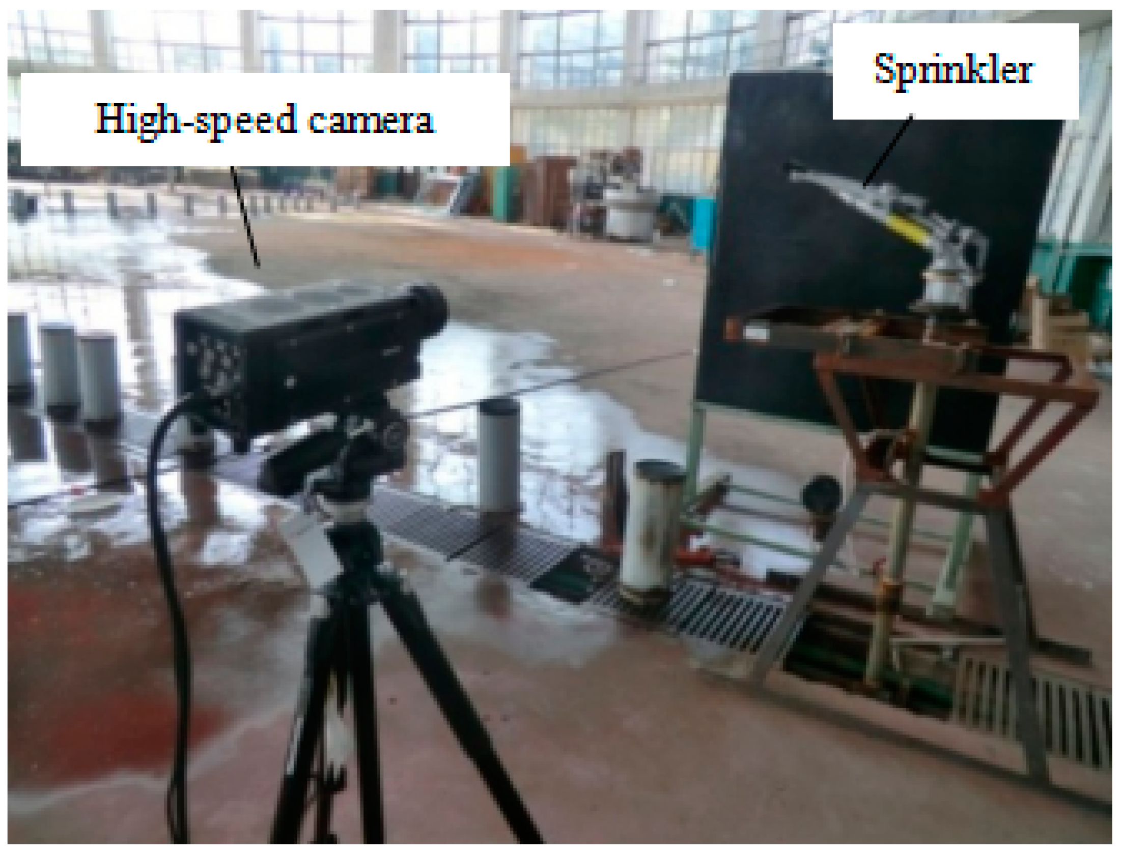
The test measurements of frequency and duration time were conducted using the test analysis system at the sprinkler irrigation laboratory of Jiangsu University. A centrifugal pump supplied water to the test system from a constant level reservoir. The working pressure was measured at the base of the sprinkler head using a pressure gauge with an accuracy tolerance of 0.4%. The high-speed camera of Motion pro Y4lm-8 (Integrated Device Technology, Inc. San Jose, CA, USA) was used. The maximum resolution is 1024 × 1024. The maximum shooting speed at full resolution is 4000 frames per second, and it can shoot continuously for about 45 s at full resolution. Figure 2 shows a general view of the experimental setup.
In order to clearly shoot the whole movement process of the drive spoon in the water jet, light-absorptive black velvet was adopted as the background and clear water was adopted for the test. A high-pressure xenon lamp was adopted as the light source for the indoor shooting to ensure a favourable light source. The spray tube was required to be kept still to shoot the whole movement state of the drive arm during the test process. The high-speed camera was placed 2.5 m away from the sprinkler, and the axis of the lens was kept vertical to the axial surface of the spray tube. In general consideration of the influence of various factors on the motion process of the drive arm, the shooting frequency was determined as 2000 f s−1. The shooting time was determined as 4 s to shoot the whole motion cycle of the drive arm.
We first determined the number of pictures, which included one whole cycle after the shooting; then the period of one cycle could be acquired by multiplying the number of pictures by the shooting frequency. Hence, the frequency of the drive spoon–dispersed water jet was the reciprocal of the period. Similarly, the duration time can be obtained by calculating the number of pictures that the drive spoon moved in the water jet during one cycle. For each test, three picture groups that each included a complete cycle were selected for measurement, and the average values of the three measurements were taken as the final test results.

2.2. Hydraulic Performance Test

A schematic of the experimental setup is shown in Figure 3. A centrifugal pump supplied water to the testing system from a constant level reservoir. Pressure was measured at the base of the sprinkler head using a pressure gauge with an accuracy tolerance of 0.4%. The catch cans used in the study for testing radial water application were cylindrical in shape with a height of 0.6 m and an inside diameter of 0.2 m. Catch cans, which were used to collect water, were spaced at 1.0 m intervals from the sprinkler in one single collector lines. The sprinkler was run for 20 min before performing the experiments in order to standardize the environmental conditions. The following standards were adopted in the design of the experimental set-up: ASAE S.330.1 [35], ASAE S.398.1 [36], and ISO 7749-2 [37]. The water collected in each can was measured using a graduated cylinder. The application rate was calculated on the basis of the diameter of the catch cans and the duration of each test. The radial application rate distributions for the sprinkler were obtained in the laboratory. Three repetitions were made for each test, and the average values were taken as the final test results.

3. Movement Theory of the Drive Arm

3.1. Analysis of the Drive Arm Movement Process

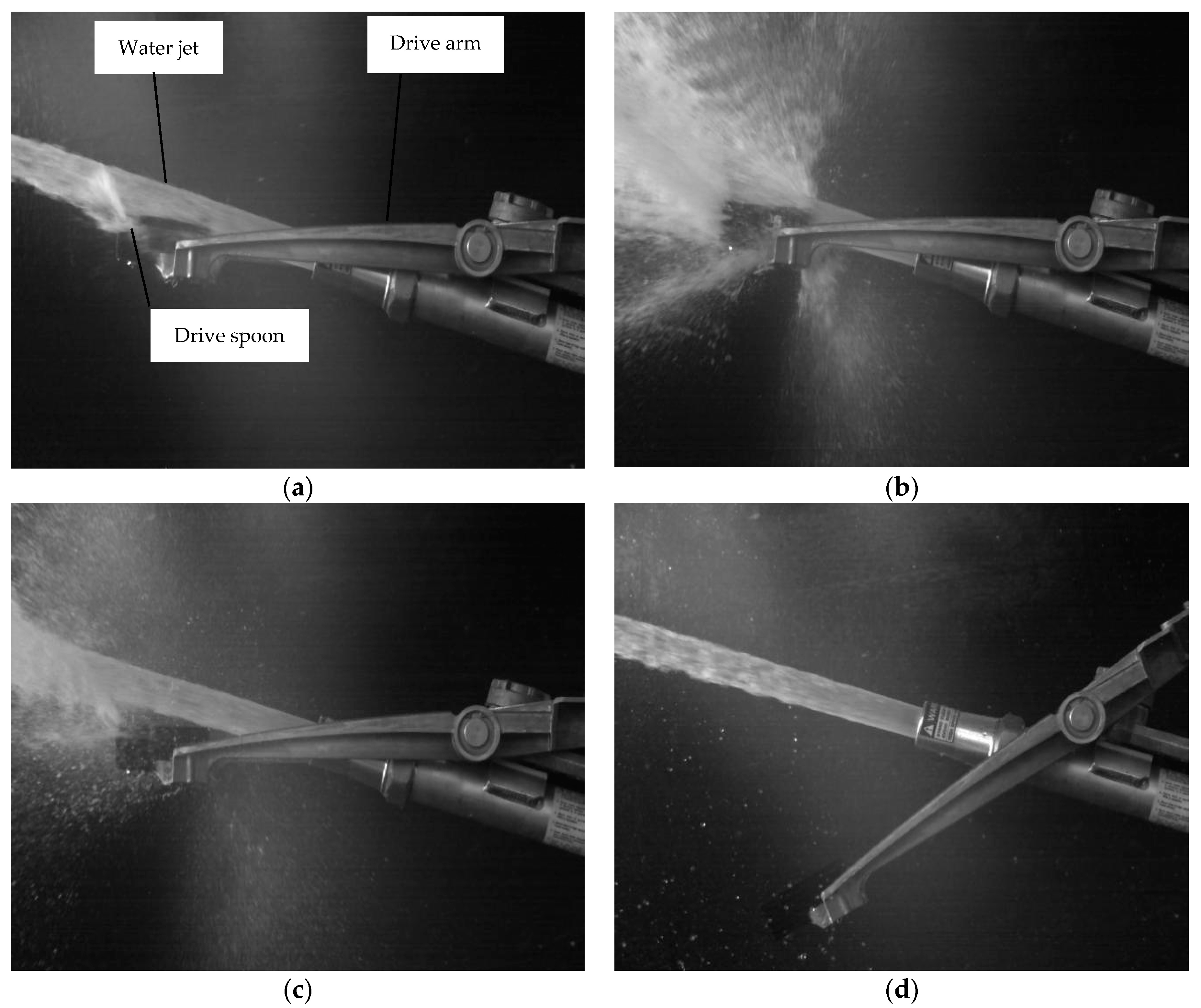
Figure 4 presents the movement process of the drive arm when the Big Gun® sprinkler was operating normally. The non-free movement means that the drive spoon moved in the water jet and as shown in Figure 4a–c. During this stage, the drive spoon was impacted by the water jet. Contrarily, the water jet was dispersed by the drive spoon and the time of non-free movement was the duration. When the drive spoon escaped completely from the water jet, the drive arm was subjected only to the influences of gravity, the frictional resistance on the rotation shaft, and the air resistance. This stage was named as the free movement process and is shown in Figure 4d.

3.2. Formula for Calculating Duration

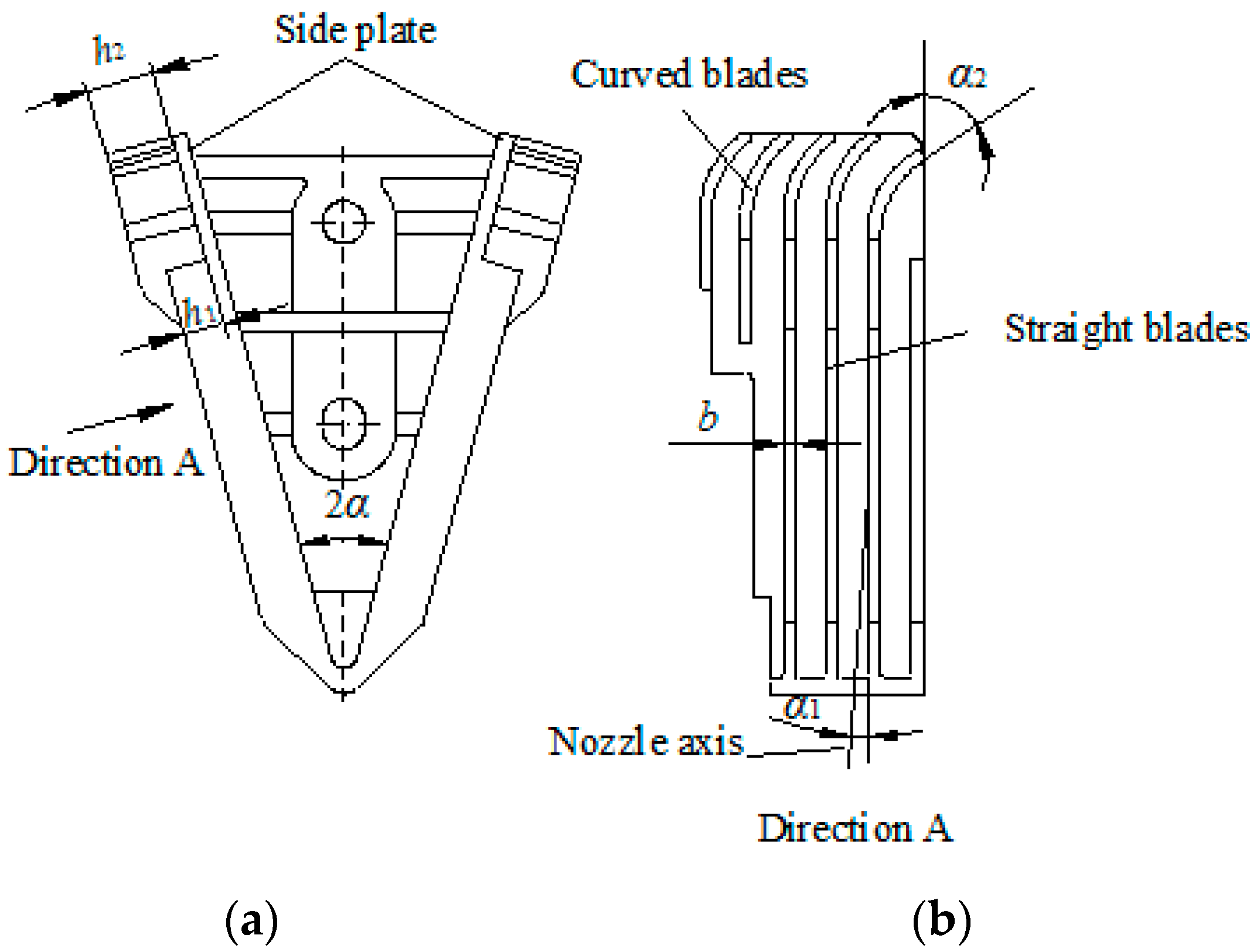
Figure 5 presents a structural diagram of the drive spoon. The curved blades generate a force that makes the arm swing downward when the water flows through the blades, which is the impact force in the vertical direction that the drive spoon obtains from the water jet. This force can be calculated from [13];
Fv = 2p·(dn·bh2·sinα2
where Fv is the force in a vertical direction (N), p is the working pressure (MPa), d is the nozzle diameter (mm), h2 is the width of the curved blades (mm), b is the blade thickness (mm), n is the number of the blades submersed by the water jet, and α2 is the outlet angle of the water jet on the curved blades (°).
The following assumptions were made for deducing the theoretical equations of the frequency: (1) frictional resistance on the rotation shaft was ignored; and (2) resistance to the drive arm caused by the air was not considered. Hence, the torque was calculated from:
Mv = 2px·(dn·bh2·sinα2
where Mv is the torque (N·m) and x is the distance between the force point and the rotation axis (m). According to the momentum theorem, the time of non-free movement can be calculated from:
t = J ω M v
where t is the time of non-free movement (s), ω is the angular velocity of the drive arm (rad s−1), and J is the moment of inertia of the drive arm about the rotation axis (kg·m2). According to the law of momentum conservation,
ω = 2 M v θ J
where θ is the rotation angle of the drive arm in the water jet (°). Substitute Equations (2) and (4) into Equation (3):
t = J θ p x d n b h 2 sin α 2
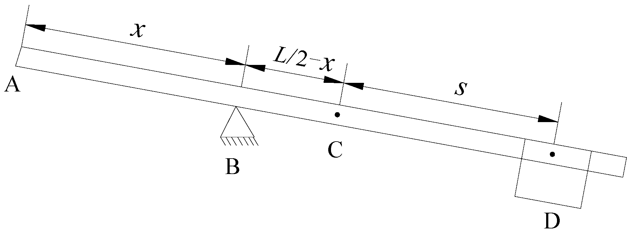
Figure 6 presents a simplified model for calculating the moment of inertia. On the premise that the mass of the drive arm was uniformly distributed, the moment of inertia can be calculated from:
J = 1 12 m L 2 + m L 2 x 2 + M s + L 2 x 2
where L is the length of the drive arm (m); s is the distance between C and D (m); m is the mass of the drive arm (kg); M is the mass of the counterweight (kg). Because the distance between B and D was the distance between the counterweight-installed position and the rotation axis, Equation (4) can be simplified to:
J = 1 12 m L 2 + m L 2 x 2 + M r 2
where r is the distance between the counterweight-installed position and the rotation axis (m).

4. Results and Discussion

4.1. Comparison between Measured and Predicted Values from Theory

The parameters of the sprinkler used for calculating the duration time are shown in Table 1. Substituting the parameters of Table 2 into Equation (5), the duration time was calculated. Table 2 presents the measured frequency, a comparison between calculated values and measured values for the duration under different working pressures, and the distance between the counterweight-installed positions.
As can be seen from Table 2, the frequency of the drive spoon–dispersed water jet increased with increased working pressure and decreased distance. However, the duration decreased with increased working pressure and decreased distance. Under the same working pressure, the frequency changed slightly with changes in distance. When the distance decreased from 135 mm to 80 mm, the growth rates of frequency with working pressures of 0.30, 0.35, and 0.40 MPa were 10.20%, 8.56%, and 6.71%, respectively. Similarly, when the distance increased from 80 mm to 135 mm, the growth rates of the duration time with the working pressures of 0.30, 0.35, and 0.40 MPa were 18.27%, 17.10%, and 17.01%, respectively. The calculated values of the theory were greater than those of the measured values. It was assumed in the derivation process that the frictional resistance on the rotation shaft and the resistance to the drive arm caused by the air were not taken into consideration, and this can lead to a higher predicted value. The maximum difference between calculated and measured values for the duration was 8.92%. Differences between the measured and predicted values decreased with increased working pressure, and the average difference decreased to 2.97% when the working pressure increased to 0.40 MPa. This was in agreement with the results found by Tang et al. [14], who established a formula to predict the impact force of the drive spoon obtained from a water jet and found that the formula had the best accuracy at high working pressures.

4.2. Influence on Hydraulic Performance

4.2.1. Comparison of Water Distribution Patterns

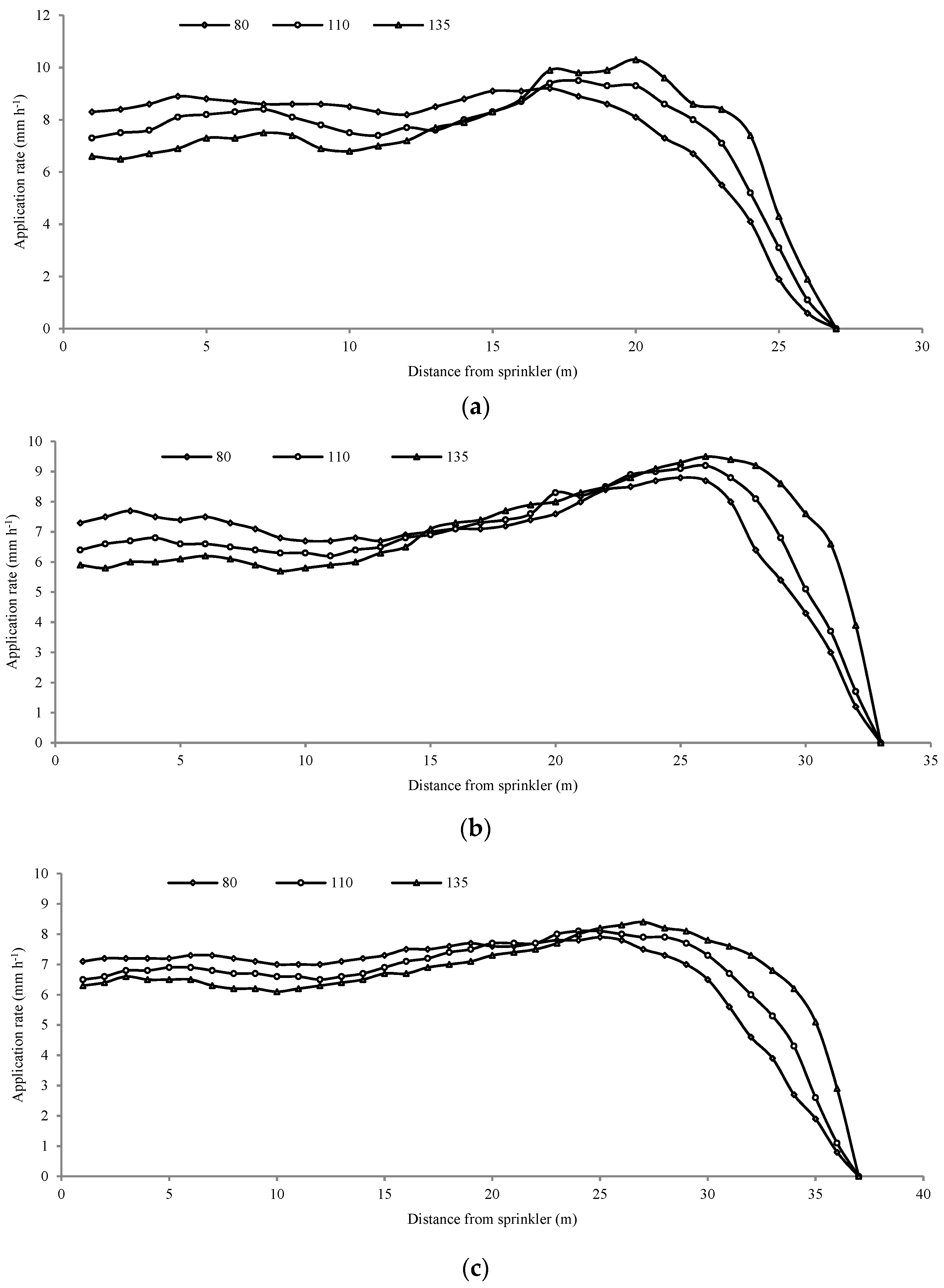
As mentioned above, the most convenient method to change the frequency and duration of the drive spoon dispersed–water jet is by adjusting the counterweight-installed position. Figure 7 presents a comparison of water distribution patterns between different counterweight-installed positions with the working pressures of 0.30, 0.35, and 0.40 MPa. As can be seen from this figure, the application rates near the sprinkler were supplemented more sufficiently when the counterweight was 80 mm for different working pressures. The water distribution at the near range (1–15 m) became increasingly uniform as the distance between counterweight and rotation axis decreased. On the one hand, this confirmed that the water jet break-up mechanism was an important device for changing the water distribution pattern [16,26]. On the other hand, the results indicated that frequency had a greater influence on the water distribution pattern than did duration. The application rates within 1–13 m improved and increased about 30% as the distance decreased from 135 mm to 80 mm; this was consistent with the above analysis. The frequency of the drive spoon–dispersed water jet was reduced when the counterweight was far away from the rotation axis, which reduced the volume of the dispersed water in short ranges. At the same time, the maximum application rates decreased from 10.3 to 9.2 mm h−1, 9.5 to 8.8 mm h−1, and 8.4 to 7.9 mm h−1 with working pressures of 0.30, 0.35, and 0.40 MPa, respectively. This was effective for reducing the risk of disruption of crops and surface runoff [38].

4.2.2. Comparison of Combined Uniformity Coefficients

MATLAB (The MathWorks, Inc. Natick, MA, USA) was used as the computational program to calculate the combined CU according to the radial application rate of water distribution [9]. Square layout is more convenient to pipeline design and irrigation system management and is widely applied in practical engineering [39]. Hence, square layout form was adopted to analyze the effect of frequency on CU values. The spacing coefficient was defined as a parameter to describe the overlapping distance of two sprinklers, and the spacing coefficient was equal to the times of the radius of the throw.
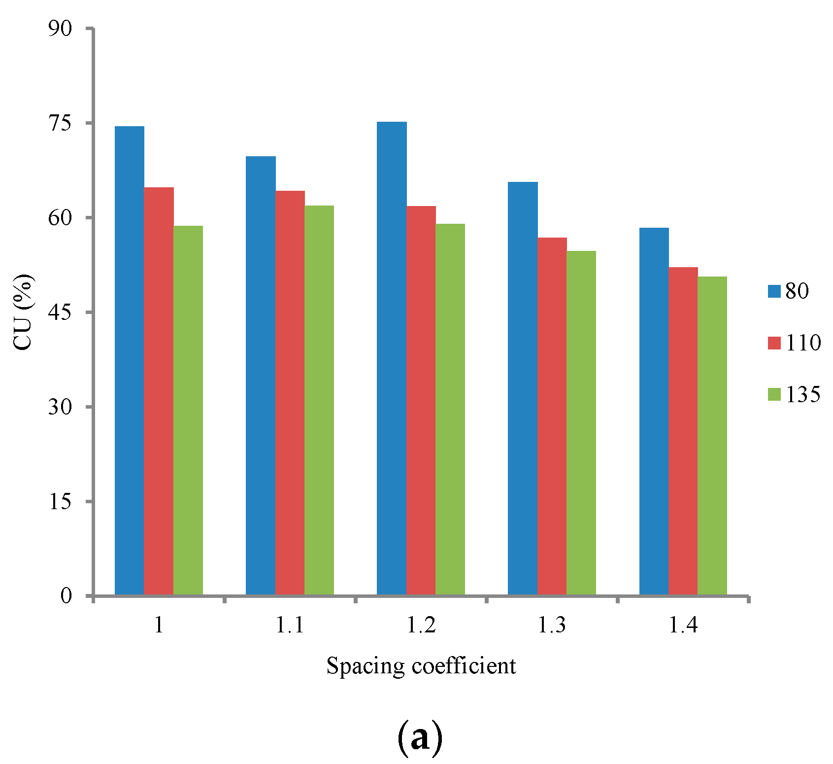
Figure 8 presents the relationships between the CU values and spacing coefficients for various counterweight-installed positions with the working pressures of 0.3, 0.35, and 0.40 MPa. Water distribution uniformity generally increased with increased working pressure [11,12,40]. For all the spacing coefficients, higher CU values were obtained at higher working pressures and lower CU values were obtained at lower working pressures. The CU values decreased as the distance between the counterweight and the rotation axis increased, which indicated that it was a useful method to improve water distribution uniformity by increasing the frequency of the drive spoon–dispersed water jet. As can be seen from Figure 8a, the maximum CU value was obtained with a spacing coefficient of 1.2 under a working pressure of 0.30 MPa, and it increased from 58.96% to 75.1% as the distance decreased from 135 mm to 80 mm. As can be seen from Figure 8b, the maximum CU value was obtained with a spacing coefficient of 1.2 under a working pressure of 0.35 MPa, and it increased from 68.85% to 80.1% as the distance decreased from 135 mm to 80 mm. As can be seen from Figure 8c, the maximum CU value was obtained with a spacing coefficient of 1.2 under a working pressure of 0.40 MPa, and it increased from 72.46% to 82.17% as the distance decreased from 135 mm to 80 mm. A comparative analysis of the increasing ranges of CU value with different spacing coefficients for 0.30 and 0.40 MPa showed that increasing the frequency under low working pressure was more effective than under high working pressure. In general, reducing the working pressure can result in decreasing the water distribution uniformity [25,26]. Hence, the results provided an effective method to maintain satisfying water distribution uniformity while decreasing energy consumption by reducing working pressure. El-Wahed et al. [41] investigated the impact of sprinkler irrigation uniformity on crop yield and water use efficiency, and indicated that high uniformity was consistent with high yield and high water-use efficiency. M. El-Marsafawy et al. [42] estimated maximum crop water productivity trends under conditions in the Northern Nile Delta over three decades, and indicated that the better the distribution of water in the field, the higher the crop yield. Therefore, the results of this study are beneficial to improve crop yield and water-use efficiency in practical applications.

5. Conclusions

The frequency increased and the duration time decreased as working pressure increased and distance between the counterweight-installed position and the rotation axis decreased. The calculated values of the theory were greater than the measured values. The maximum difference between the calculated and measured values for the duration time was 8.92%. Differences between the measured and predicted values decreased with increased working pressure, and the average difference decreased to 2.98% when the working pressure increased to 0.40 MPa.
Frequency had a greater influence on the water distribution pattern than did duration. The water distribution at the near range became more and more uniform with decreased distance between the counterweight and the rotation axis. The application rates within 1–13 m improved and increased about 50% as the distance decreased from 135 mm to 80 mm. The maximum application rates decreased from 10.3 to 9.2 mm h−1, 9.5 to 8.8 mm h−1, and 8.4 to 7.9 mm h−1 with working pressures of 0.30, 0.35, and 0.40 MPa, respectively. The user can adjust the position of the counterweight reasonably according to the allowable application rate by different crops.
The CU values decreased as the distance between the counterweight and the rotation axis increased. The maximum CU values were obtained at spacing coefficients of 1.2, 1.2, and 1.1 for working pressures of 0.30, 0.35, and 0.40 MPa, respectively. As distance decreased from 135 mm to 80 mm, the maximum CU values increased from 58.96% to 75.1%, 68.85% to 80.1%, and 72.46% to 82.17% for working pressures of 0.30, 0.35, and 0.40 MPa, respectively. Increasing the frequency under low working pressure was more effective than under high working pressure. Improving irrigation water distribution uniformity will be beneficial to improve crop yield and water use efficiency in practical applications.

Author Contributions

P.T. and C.C. conceived and structured the testing system. C.C. performed the literature search, helped in the experiments, and analyzed the test data. P.T. and C.C. wrote the paper and approved the submitted version of the manuscript. All authors have read and agreed to the published version of the manuscript.

Funding

This study was supported by the National Natural Science Foundation of China (51939005), the Key Research and Development Program of Jiangsu Province (BE2021379), and the Demonstration and Promotion Project of Modern Agricultural Machinery Equipment and Technology of Jiangsu Province (NJ2021-24), the Key Laboratory of Water-Saving Agriculture of Henan Province Open Project (FIRI2021020301).

Data Availability Statement

Data is contained within the article.

Acknowledgments

The authors are thankful to the editor and reviewers for their valuable comments in improving the quality of this paper.

Conflicts of Interest

The authors declare no conflict of interest.

References

  1. Xu, Z.D.; Li, H.; Xiang, Q.J.; Wang, J.H.; Jiang, Y.; Liu, J. Effect on combination irrigation of low pressure 20PY2 impact sprinkler with and without aeration. J. Drain. Irrig. Mach. Eng. 2022, 40, 74–79. [Google Scholar]
  2. Pei, S.S.; Li, Y.J.; Yan, H.J.; Gu, T. Effects of nitrogen treatments on potato nitrogen accumulation and soil nitrate-nitrogen distribution under sprinkler fertigation system. J. Drain. Irrig. Mach. Eng. 2022, 40, 745–750. [Google Scholar]
  3. Ouazaa, S.; Burguete, J.; Zapata, N. Solid-set sprinklers irrigation of field boundaries: Experiments and modeling. Irrig. Sci. 2016, 34, 85–103. [Google Scholar] [CrossRef]
  4. Yan, H.J.; Hui, X.; Li, M.N.; Xu, Y. Development in sprinkler irrigation technology in China. Irrig. Drain. 2020, 69, 75–87. [Google Scholar] [CrossRef]
  5. Liu, J.P.; Zhu, X.Y.; Yuan, S.Q.; Li, H.; Tang, Y. Research and development trend of agricultural water-saving sprinkler and micro-irrigation equipment in China. J. Drain. Irrig. Mach. Eng. 2022, 40, 87–96. [Google Scholar]
  6. Pinto, M.A.B.; Parfitt, J.M.B.; Timm, L.C.; Faria, L.C.; Concenço, G.; Stumpf, L.; Nörenberg, B.G. Sprinkler irrigation in lowland rice: Crop yield and its components as a function of water availability in different phenological phases. Field Crops Res. 2020, 248, 107714. [Google Scholar] [CrossRef]
  7. Yuan, Y.; Lin, F.; Maucieri, C.; Zhang, Y. Efficient irrigation methods and optimal nitrogen dose to enhance wheat yield, inputs efficiency and economic benefits in the north China plain. Agronomy 2022, 12, 273. [Google Scholar] [CrossRef]
  8. Hua, L.; Jiang, Y.; Li, H.; Qin, L.T. Effects of different nozzle orifice shapes on water droplet characteristics for sprinkler irrigation. Horticulturae 2022, 8, 538. [Google Scholar] [CrossRef]
  9. Zhu, X.Y.; Yuan, S.Q.; Jiang, J.Y.; Liu, J.P.; Liu, X.F. Comparison of fluidic and impact sprinklers based on hydraulic performance. Irrig. Sci. 2015, 33, 367–374. [Google Scholar] [CrossRef]
  10. Mazzetto, F.; Calcante, A.; Orsi, E. Design, development, and evaluation of a device for the monitoring of liquid manure distribution using big gun sprinkler distribution systems. Appl. Eng. Agric. 2011, 27, 569–576. [Google Scholar] [CrossRef]
  11. Osman, M.; Hassan, S.B.; Yusof, K.B.W. Effect of combination factors of operating pressure, nozzle diameter and riser height on sprinkler irrigation uniformity. Appl. Mech. Mater. 2014, 695, 380–383. [Google Scholar]
  12. Sheikhesmaeili, O.; Montero, J.; Laserna, S. Analysis of water application with semi-portable big size sprinkler irrigation systems in semi-arid areas. Agric. Water Manag. 2016, 163, 275–284. [Google Scholar] [CrossRef]
  13. Ge, M.S.; Wu, P.T.; Zhu, D.L.; Zhang, L. Analysis of kinetic energy distribution of big gun sprinkler applied to continuous moving hose-drawn traveler. Agric. Water Manag. 2018, 201, 118–132. [Google Scholar] [CrossRef]
  14. Tang, P.; Li, H.; Issaka, Z.; Chen, C. Impact forces on the drive spoon of a large cannon irrigation sprinkler: Simple theory, CFD numerical simulation and validation. Biosys. Eng. 2017, 159, 1–9. [Google Scholar] [CrossRef]
  15. Yao, J.C.; Wang, X.K.; Zhang, S.C.; Xu, S.R.; Jin, B.B.; Ding, S.W. Orthogonal test of important parameters affecting hydraulic performance of negative pressure feedback jet sprinkler. J. Drain. Irrig. Mach. Eng. 2021, 39, 966–972. [Google Scholar]
  16. Tarjuelo, J.M.; Montero, J.; Honrubia, F.T.; Ortiz, J.J.; Ortega, J.F. Analysis of uniformity of sprinkle irrigation in a semi-arid area. Agric. Water Manag. 1999, 40, 315–331. [Google Scholar] [CrossRef]
  17. Liu, J.P.; Li, T.; Zhang, Q. Experimental study on influence of flow channel structure on hydraulic performance of low-pressure rotary sprinkler. J. Drain. Irrig. Mach. Eng. 2021, 39, 312–317. [Google Scholar]
  18. Liu, J.P.; Yuan, S.Q.; Li, H.; Zhu, X.Y. Numerical simulation and experimental study on a new type of variable-rate fluidic sprinkler. J. Agric. Sci. Tech. 2013, 15, 569–581. [Google Scholar]
  19. Burt, C.M.; Clemmens, A.J.; Strelkoff, T.S.; Solomon, K.H.; Bliesner, R.D.; Hardy, L.A.; Howell, T.A.; Eisenhauer, D.E. Irrigation performance measures: Efficiency and uniformity. J. Irrig. Drain. Eng. 1997, 123, 423–442. [Google Scholar] [CrossRef]
  20. Zhu, X.Y.; Yuan, S.Q.; Liu, J.P. Effect of sprinkler head geometrical parameters on hydraulic performance of fluidic sprinkler. J. Irrig. Drain. Eng. 2012, 138, 1019–1026. [Google Scholar] [CrossRef]
  21. Ge, M.S.; Wu, P.T.; Zhu, D.L.; Zhang, L. Application of different curve interpolation and fitting methods in water distribution calculation of mobile sprinkler machine. Biosyst. Eng. 2018, 174, 316–328. [Google Scholar] [CrossRef]
  22. Ge, M.S.; Wu, P.T.; Zhu, D.L.; Zhang, L. Comparisons of spray characteristics between vertical impact and turbine drive sprinklers—A case study of the 50PYC and HY50 big gun-type sprinklers. Agric. Water Manag. 2020, 228, 105847. [Google Scholar] [CrossRef]
  23. Kincaid, D.C. Impact sprinkler pattern modification. Trans. ASAE 1991, 34, 2397–2403. [Google Scholar] [CrossRef]
  24. Tarjuelo, J.M.; Montero, J.; Carrion, P.A.; Honrubia, F.T.; Calvo, M.A. Irrigation uniformity with medium size sprinklers part ii: Influence of wind and other factors on water distribution. Trans. ASAE 1999, 42, 677–690. [Google Scholar] [CrossRef]
  25. Silva, L.L. The effect of spray head sprinklers with different deflector plates on irrigation uniformity, runoff and sediment yield in a Mediterranean soil. Agric. Water Manag. 2006, 85, 243–252. [Google Scholar] [CrossRef]
  26. Li, H.; Jiang, Y.; Xu, M.; Li, Y.M.; Chen, C. Effect on hydraulic performance of low-pressure sprinkler by an intermittent water dispersion device. Trans. ASABE 2016, 59, 521–532. [Google Scholar]
  27. Li, H.; Liu, Z.C.; Tang, P.; Wang, C. Finite element analysis of arm of SR100 vertical impact sprinkler. J. Drain. Irrig. Mach. Eng. 2014, 30, 368–372. [Google Scholar]
  28. Issaka, Z.; Li, H.; Jiang, Y.; Tang, P.; Chen, C.; Darko, R.O. Hydraulic performance characteristics of impact sprinkler with a fixed water dispersion device. Int. J. Agric. Biol. Eng. 2018, 11, 104–112. [Google Scholar] [CrossRef]
  29. Pascal, M.; Kadem, N.; Tchiftchibachian, A. Investigation of the influence of sprinkler fins and dissolved air on jet flow. J. Irrig. Drain. Eng. 2006, 132, 41–46. [Google Scholar] [CrossRef]
  30. Jiang, Y.; Chen, C.; Li, H.; Xiang, Q.J. Influences of nozzle parameters and low-pressure on jet breakup and droplet characteristics. Int. J. Agric. Biol. Eng. 2016, 9, 22–32. [Google Scholar]
  31. Zhu, X.Y.; Zhang, A.Y.; Zhang, L.G.; Shi, Y.J.; Jiang, N. Research on atomization performance of low-pressure atomization nozzle. J. Drain. Irrig. Mach. Eng. 2021, 39, 210–216. [Google Scholar]
  32. Robles, O.; Playán, E.; Cavero, J.; Zapata, N. Assessing low-pressure solid-set sprinkler irrigation in maize. Agric. Water Manag. 2017, 191, 37–49. [Google Scholar] [CrossRef]
  33. AL-agele, H.A.; Mahapatra, D.M.; Nackley, L.; Higgins, C. Economic viability of ultrasonic sensor actuated nozzle height control in center pivot irrigation systems. Agronomy 2022, 12, 1077. [Google Scholar] [CrossRef]
  34. Tang, P.; Chen, C.; Li, H. Improving water distribution uniformity by optimizing the structural size of the drive spoon blades for a vertical impact sprinkler. Sustainability 2020, 12, 7574. [Google Scholar] [CrossRef]
  35. ASAE Standards, S330.1; Procedure for Sprinkler Distribution Testing for Research Purposes. 32nd ed. ASAE: Washington, DC, USA; St. Joseph, MI, USA, 1985.
  36. ASAE Standards, S398.1; Procedure for Sprinkler Testing and Performance Reporting. 32nd ed. ASAE: Washington, DC, USA; St. Joseph, MI, USA, 1985.
  37. ISO 7749-2; Agricultural Irrigation Equipment—Rotating Sprinklers—Part 2: Uniformity of Distribution and Test Methods. International Standards Organization: Geneva, Switzerland, 1990.
  38. King, B.A. Moving spray-plate center-pivot sprinkler rating index for assessing runoff potential. Trans. ASABE 2016, 59, 225–237. [Google Scholar]
  39. Wang, X.; Li, G.; Guo, C.C.; Han, W.T.; Yao, X.M.; Sun, Y. Optimization of impact sprinkler sub-nozzle parameters of elevation angle and position. Trans. CSAE 2015, 31, 89–95. [Google Scholar]
  40. Shi, Y.J.; Zhu, X.Y.; Hu, G.; Zhang, A.Y.; Li, J.P. Effect of water distribution on different working conditions for sprinkler irrigation. J. Drain. Irrig. Mach. Eng. 2021, 39, 318–324. [Google Scholar]
  41. El-Wahed, A.; Medici, M.; Lorenzini, G. Sprinkler irrigation uniformity: Impact on the crop yield and water use efficiency. J. Eng. Thermophys. 2016, 25, 117–125. [Google Scholar] [CrossRef]
  42. El-Marsafawy, S.M.; Swelam, A.; Ghanem, A. Evolution of crop water productivity in the Nile Delta over three decades (1985–2015). Water 2018, 10, 1168. [Google Scholar] [CrossRef] [Green Version]
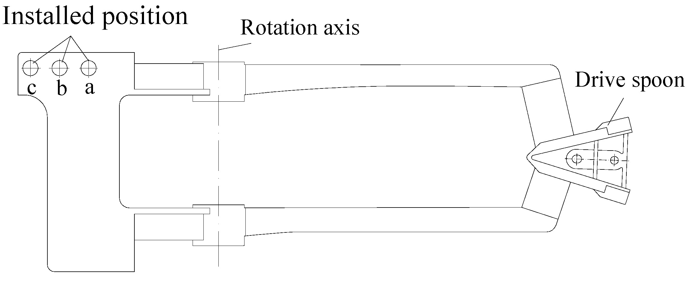
Figure 1. Schematic diagram of the drive arm.
Agronomy 12 02233 g001
Figure 2. General view of the experimental setup.
Agronomy 12 02233 g002
Figure 3. Schematic diagram of the experimental system in the laboratory.
Agronomy 12 02233 g003
Figure 4. Movement process of the drive arm: (a) drive spoon began to cut into water jet; (b) drive spoon in water jet; (c) drive spoon starting out of water jet, (d) drive spoon completely out of water jet.
Agronomy 12 02233 g004
Figure 5. Structural diagram of the drive spoon: (a) top view of drive spoon; (b) view from direction A. α is the angle between the straight blades and the centreline of water jet (°); α1 is the angle of straight blades into the water jet (°); α2 is the outlet angle of the water jet on the curved blades (°); h1 is the width of the straight blade (mm); h2 is the width of the curved blade (mm); b is the blade thickness (mm).
Agronomy 12 02233 g005
Figure 6. Simplified model for calculating the moment of inertia: A is the front of the drive arm; B is the rotation axis; C is the mass center of the drive arm; D is the counterweight-installed position; x is the distance between A and B (mm); L is the length of the drive arm (mm); and s is the distance between C and D (mm).
Agronomy 12 02233 g006
Figure 7. Water distribution patterns with different counterweight-installed positions: (a) working pressure of 0.30 MPa; (b) working pressure of 0.35 MPa; (c) working pressure of 0.40 MPa.
Agronomy 12 02233 g007
Figure 8. Relationships between CU values and spacing coefficients with different counterweight- installed positions. (a) working pressure of 0.30 MPa, (b) working pressure of 0.35 MPa, (c) working pressure of 0.40 MPa.
Agronomy 12 02233 g008aAgronomy 12 02233 g008b
Table 1. Parameters for calculating duration using the theory.
d (mm)b (mm)h2 (mm)α2 (°)nx (m)θ(°)m (kg)M (kg)L (m)
25.51104550.32520.70.740.49
Table 2. Measured frequency, comparison between calculated values and measured values for the duration under different working pressures, and distance between counterweight-installed positions.
Working Pressure (MPa)Distance between Counterweight- Installed Position and Rotation Axis (mm)Frequency (Hz)Duration Time
Calculated (s)Measured
(s)
Difference (%)
0.30801.2100.05730.05308.11
1101.1650.06230.05728.92
1351.0980.06730.06287.17
0.35801.2930.05310.05035.57
1101.2430.05770.05504.91
1351.1910.06230.05885.95
0.40801.3200.04960.04822.90
1101.2680.05400.05272.47
1351.2370.05830.05633.55
Publisher’s Note: MDPI stays neutral with regard to jurisdictional claims in published maps and institutional affiliations.