Article

Simulation Study for Overturning and Rollover Characteristics of a Tractor with an Implement on a Hard Surface

1
Department of Biosystems Engineering, Kangwon National University, 1 Kangwondaehak-gil, Chuncheon 24341, Republic of Korea
2
Interdisciplinary Program in Smart Agriculture, Kangwon National University, 1 Kangwondaehak-gil, Chuncheon 24341, Republic of Korea
*
Author to whom correspondence should be addressed.
Agronomy 2022, 12(12), 3093; https://doi.org/10.3390/agronomy12123093
Submission received: 7 November 2022 / Revised: 5 December 2022 / Accepted: 5 December 2022 / Published: 6 December 2022
(This article belongs to the Section Precision and Digital Agriculture)

Abstract

:
The effects of the slope of the ground and the obstacle conditions on the lateral overturning/backward rollover of a tractor with an implement were analyzed through dynamic simulation. The tractor and implement’s 3D simulation model was constructed. As for simulation conditions, four heights and three shapes were set for obstacles, and eight slopes were set for the ground to be traveled by the implemented tractor. Under each condition, the critical speed at which the tractor begins to overturn and roll over was derived, and factors that caused the overturn and rollover were analyzed. As a result of instability types, backward rollover happens when the ground slope is low and lateral overturning happens at a specific slope or higher regardless of the obstacle conditions. In the case of the tractor and implement under study, the tendency changed at a slope of 25°. As the obstacle height increased, overturning and rollover safety decreased. In the case of the obstacle shape, safety was lowest for the rectangular obstacle and highest for the right-side triangular obstacle. The driving safety of the tractor with the implement was lower than that of the tractor with no implement. This appears to be mainly due to the change in the position of the center of gravity caused by the attached implement. The critical speed of the tractor with the implement was 3.26 times lower than that of the tractor with no implement on average. It is judged that the safety of the implemented tractor can be identified by using this study.

1. Introduction

For rural areas in South Korea, aging and feminization are intensifying as the proportion of people aged 65 years and over is 42.3% as of 2020 [1]. Accordingly, the mechanization rate of agriculture is increasing, and more agricultural machines are being disseminated [2,3]. Among them, the use of agricultural tractors was as high as 29.2% in 2020 [4]. However, the mechanization of agricultural work is also increasing safety accidents [5]. In 2021, 44,302 agricultural machinery accidents occurred in Korea, and 26.37% of those (11,683 accidents) were lateral overturning and backward rollover accidents [6]. In addition, the accidents caused by the overturning and rollover of agricultural machines represent more than half of all tractor-related deaths worldwide [7]. In Italy, approximately 160 fatal accidents occur each year, and the most common cause is the overturning and rollover of tractors [8].
In the case of agricultural tractors, various implements, such as plows and rotavators, can be attached to perform desired work. However, when agricultural work is performed by attaching implements, the risk of overturning and rollover may increase. Uneven fields and a high ground slope are the major causes of accidents related to agricultural work that utilizes tractors [9]. Accordingly, various studies have been conducted to analyze the driving safety of tractors equipped with various implements. Iman (2011) developed a tractor dynamics model according to the driving speed, the slope of the ground, and the friction coefficient between wheels and ground when the tractor’s lateral overturning occurs on the slope due to external factors. The model confirmed that the safety of lateral overturning increases as the angle and driving speed of the slope decrease [10]. Li et al. (2013) developed a dynamic mathematical model of a tractor equipped with a front-end loader and analyzed safety against overturning and rollover through simulation and scale-down model tests [11]. The developed model is described as effective in analyzing the safety against loader attachment. Ahmadi (2013) introduced the longitudinal stability index and analyzed the safety of a tractor equipped with a plow against overturning and rollover under working and driving conditions [12]. The risk of switching from the working situation to the transportation situation was identified. Previati et al. (2014) theoretically analyzed the tractor model and analyzed the safety of agricultural tractors against backward rollover. It was found that when one wheel loses contact with the ground, it becomes very unstable, and the suspension system of the front axle can greatly increase the safety of the tractor [13]. Li et al. (2015) formulated a mathematical model to derive factors affecting lateral overturning/backward rollover and slip. It was derived that the driving speed of the tractor and the slope of the ground have a significant effect on accident safety and that the maximum static friction coefficient affects the slip of the tractor [14]. Li et al. (2016) analyzed the influence of such factors as the tire type, ballast weight, track width, and implement position on overturning through scale-down model tests on an implemented tractor [15]. Choi et al. (2017) analyzed the safety of a tractor equipped with an asymmetric tractor–harvester system against overturning through theoretical analysis and simulation [16]. Shim et al. (2018) analyzed the static and dynamic safety of rear overturning of 33 kW and 55 kW class tractors with thick formers attached through the front and rear wheel load calculations. It is suggested that lowering the position of the center of gravity can increase the safety of the backward rollover of the tractor [17]. Chowdhury et al. (2020) assessed the safety of a tractor equipped with a radish harvester against overturning [18]. Lysych (2020) assessed the safety of a tractor equipped with front and rear implements against overturning through dynamic simulation [19]. Qiao and Wei (2021) performed a dynamic simulation on a tractor equipped with a momentum flywheel system at the front and assessed its safety against overturning and rollover [20]. Through the introduction of the momentum flywheel system, it was derived that it could be safely driven on uneven roads. Kang et al. (2022) derived the critical angle of the lateral overturning of the tractor under various working machine attachment conditions, such as cargo and pepper harvester, and performed a regression analysis on each coordinate of the center of gravity to confirm that the load is applied. The lateral overturning angles were derived as 28.64° and 21.04° in the roll direction and the pitch direction, respectively, and the important center of gravity coordinates were found to be the pitch direction for pepper harvesters and the roll direction for cargo [21].
Some studies have been conducted on the effects of some factors on the safety of implemented tractors against overturning and rollover. However, few studies have analyzed overturning and rollover tendencies when ground slope and obstacle conditions are applied in combination. Studies that compared safety according to the attachment of implements are also insufficient. In this study, the driving safety of a tractor with an implement according to the ground slope and obstacle conditions when it drives on a hard surface was analyzed through dynamic simulation. In addition, the safety tendency according to the implement was analyzed through a comparison with a previous study that examined the overturning and rollover tendencies of a tractor without any implements [22].

2. Materials and Methods

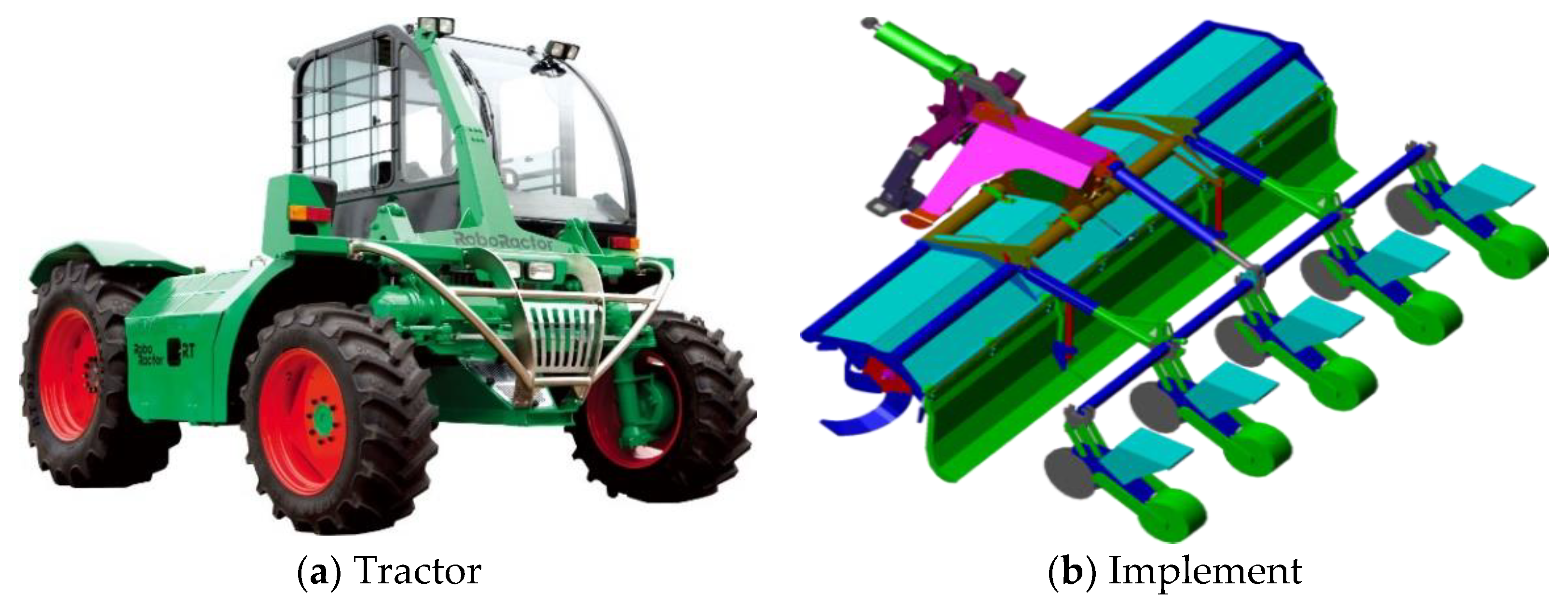
2.1. Tractor and Implement Used

Figure 1 shows the tractor and implements used in this study. Their main specifications are listed in Table 1 and Table 2. The tractor has 12 gear ratios, and its maximum forward speed is 48.81 km h−1 [22]. The static sidelong falling angle and minimum turning radius of the tractor were measured to be 45.3° and 3060 mm, respectively, by the Korea Agriculture Technology Promotion Agency, an accredited testing agency of the Organization for Economic Cooperation and Development (OECD). The implement was a combined implement that can perform several agricultural tasks simultaneously by attaching a rotavator, soil covering device, hiller, and planter. The combined implement has been commonly used in south Korea owing to benefits in terms of the purchase cost and working time compared with individual implements, but it may significantly affect overturning and rollover when attached to a tractor owing to its heavy weight.

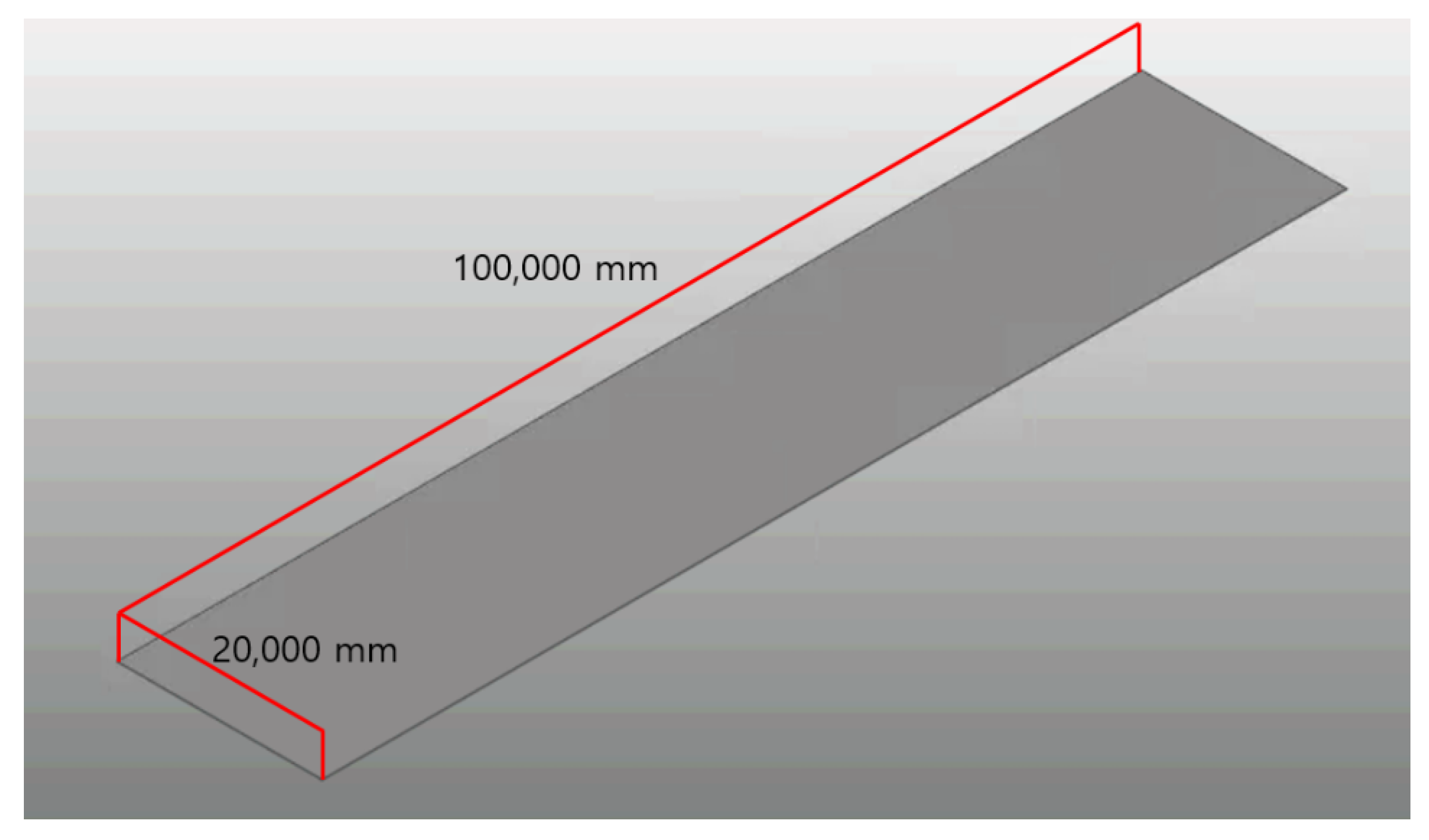
2.2. Modeling for the Dynamic Simulation

To perform dynamic simulation, a 3D model was created using the actual dimensions of the tractor and the implement (Figure 2). The 3D model consists of a tractor and an implement, and the tractor is composed of front wheels, rear wheels, and a body. When the tractor travels, it moves while the implement is lifted to the highest point. This was reflected in the modeling, and the state wherein the implement was mounted on the tractor’s three-point hitch and lifted to the highest point was applied.
Accurate material properties need to be input into the 3D model to derive accurate results from the dynamic simulation [23]. The material properties were input considering the actual components of the tractor and the implement. The body and engine frame of the tractor and the rotary blades of the implement were made of alloy steel (AISI 4140), whereas the exterior and wheels of the tractor were made of stainless steel (STS304). The implement frame was made of high-tensile steel (ATOS-80). The tires of the tractor were made of synthetic rubber, whereas the seeding box attached to the implement was made of PE plastic. The material properties of each material were derived through a literature review and applied to the dynamic simulation. Table 3 shows the material properties of the tractor and implement applied in this study [24,25,26,27,28,29]. After applying these properties, we found that the weights of the 3D-modeled tractor and the implement agreed well with the actual product.

2.3. Verification of the Simulation Model [21]

In this study, the dynamic simulation was performed using commercial multibody dynamic simulation software (RecurDyn V9R4, FunctionBay, Republic of Korea). This software can effectively solve multibody dynamic problems for both rigid and flexible bodies [30,31].
To verify the simulation model, the minimum turning radius and static sidelong falling angle of the tractor were derived from the simulation and compared with the accredited certification test results under the same conditions (Figure 3 and Figure 4). The errors were observed to be 1.31% and 4.19% for the minimum turning radius and static sidelong falling angle, respectively (Table 4). As the errors are less than 5%, the dynamic simulation model of the tractor used in this study is judged to be valid. The accredited certification test was not conducted on the tractor equipped with the implement because it is mainly targeted at individual tractors. As the dynamic simulation model of the tractor is valid and the overall modeling was performed by accurately reflecting the shape and weight information of the implement, it can be judged that the simulation model of the tractor with the implement is also valid.

2.4. Simulation Conditions

The tractor with the implement was set to travel on plain concrete, a hard surface. In the simulation, flat ground with a length of 100,000 mm and a width of 20,000 mm was constructed (Figure 5). The material properties between the tractor wheels and the ground, such as stiffness, dynamic friction coefficient, and static friction coefficient, were derived through a literature review (Table 5) [22]. When the tractor travels, phase I rollover begins, as the rear wheel located on the top of the slope is lifted from the ground first, making the tractor unstable [32]. Therefore, the rear wheel on the top of the slope was set to climb over an obstacle, and the critical speed at which the tractor begins to overturn and rollover was derived under different ground slopes and obstacle conditions. Figure 6 shows the dynamic simulation environment.
The topography of Korea is classified into six levels (less than 1°, 1° to 5°, 5° to 10°, 10° to 15°, 15° to 20°, and over 20°) according to the slope angle [33]. Preliminary analysis showed that the tractor with the implement applied in this study overturns before contact with an obstacle at a ground slope angle of 40° or higher. Therefore, the maximum slope angle was set to 35°, and eight slope angles (1° and 5° to 35° at intervals of 5°) were selected. In the case of the obstacle geometry, sinusoidal, right triangular, and rectangular obstacles were selected in this study because these shapes are generally applied to studies for identifying the influence of obstacles [14] (Figure 7). Considering the tractor wheel width, the length and width of the obstacles were set to 500 and 2000 mm, respectively. As the furrow height in Korean farmland ranges from 100 to 300 mm, the obstacle height was set to 100, 200, 300, and 400 mm [34,35,36,37].

3. Results and Discussion

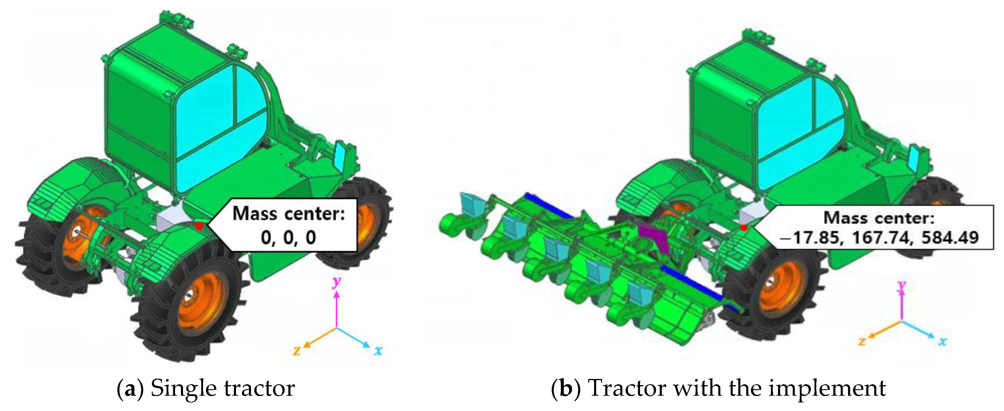
3.1. Position of Center of Gravity

The center of gravity (COG) of the tractor with the implement was derived from the simulation model (Figure 8) and compared with that of the tractor without the implement. The COG of the tractor with the implement moved by −17.85 mm on the x-axis, 167.74 mm on the y-axis, and 584.49 mm on the z-axis compared with that of the tractor without the implement. Theoretically, the tractor with the implement is more vulnerable to overturning and rollover because its COG is relatively higher and shifted toward the rear axle compared with the tractor without the implement [38].

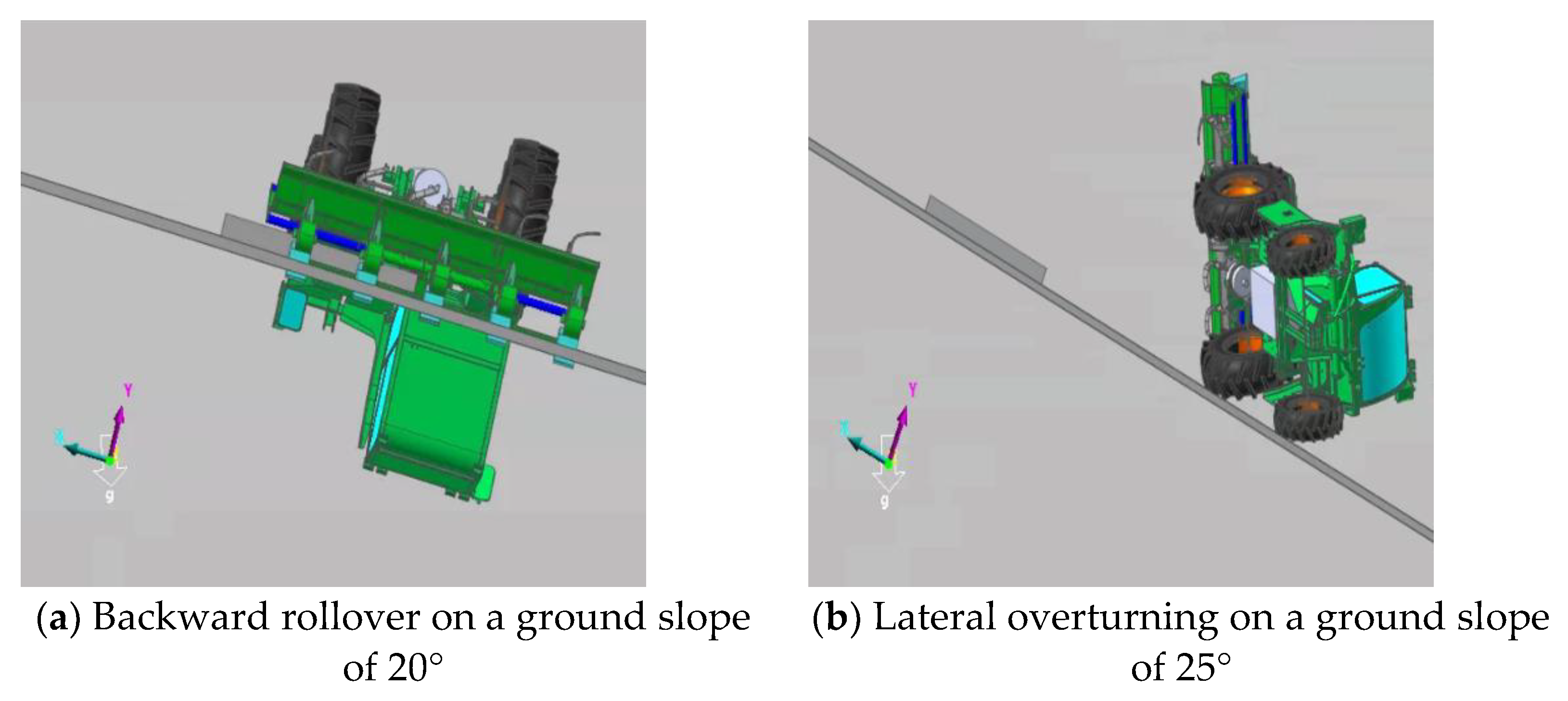
3.2. Types of Instability According to Slope of the Ground

Through the dynamic simulation, the overturning and rollover tendencies of the tractor according to the ground slope were analyzed (Figure 9). For the tractor with the implement, backward rollover occurred when the slope of the ground was less than 25°, and lateral overturning occurred when the slope of the ground was 25° or higher, regardless of the obstacle’s shape and height. In a previous study, rollover switched to overturning at a ground slope of 30° for a tractor with no implement [22]. Guzzomi (2012) derived the slope angle at which the phase I rollover occurs by equation (1). When the implement is attached to the tractor, s 1 decreases and h b increases owing to the change in the position of the center of gravity [32]. Therefore, the lateral overturning of the tractor with the implement theoretically begins to occur at a lower ground slope. The simulation results also showed that the tractor with the implement is more vulnerable to overturning than the tractor without the implement because the slope angle at which overturning occurs decreased.
θ r = t a n 1 w   s s 1 2 h b s h 1 s 1
where θ r is the lateral overturning angle when the rear wheel located above the slope is lifted from the ground, w is the track width (m), s is the wheelbase (m), s 1 is the horizontal distance between the center of gravity and the rear axle (m), h b is the height of the center of mass (m), and h 1 is the height of the front axle pivot (m).
Figure 10 shows the rotational angles of the COG in the roll and pitch directions when overturning and rollover occurred at an obstacle height of 300 mm. Overturning occurs when the roll angle is relatively larger, and rollover occurs when the pitch angle is relatively larger. In situations where backward rollover occurs, the slope of the ground is relatively small, so the angular velocity in the pitch direction of the center of gravity of the tractor is large. However, it is judged that the slope of the ground in the situation where lateral overturning occurs is relatively high, and the roll direction’s angular velocity increases when the tractor becomes unstable.
Figure 11 shows the reaction forces of each tire in the lateral, vertical, and longitudinal directions when lateral overturning occurs under the conditions of a ground slope angle of 30° and a 200 mm high rectangular obstacle. Similar tendencies were also observed under different slopes of the ground and obstacle conditions. Lateral and longitudinal forces exhibit lower reaction forces compared with the vertical force; the reaction force tendency was analyzed with a focus on the vertical force. When the tractor with the implement traveled on the slope, the tires located at the bottom slope showed higher reaction forces than those located on the top of the slope, and the reaction forces of the rear wheels were higher than those of the front wheels. When overturning occurred as the tractor climbed over the obstacle, the reaction forces of the three tires, except for the rear tire at the bottom of the slope, converged to zero, whereas that of the rear wheel at the bottom of the slope sharply increased and then converged to zero. This indicates that the rear tire at the bottom side acts as a pivot point with the ground when overturning occurs.
Figure 12 shows the reaction forces of each tire in the lateral, vertical, and longitudinal directions when backward rollover occurred under the conditions of a ground slope of 1° and a 200 mm high rectangular obstacle. As with the overturning analysis, the reaction force tendency was analyzed with a focus on the vertical force because the vertical force was higher than the lateral force and longitudinal force. When the tractor climbed over the obstacle, the reaction forces of the three tires, except for the front wheel at the bottom of the slope, converged to zero, whereas that of the front wheel at the bottom side rapidly increased and then converged to zero. This indicates that the front wheel at the bottom of the slope acts as a pivot point with the ground when rollover occurs.
A comparison with a previous study [22] showed that the total reaction force of the tractor with the implement was higher than that of the tractor with no implement. This appears to be due to the effect of the weight of the implement. Regardless of the attachment of the implement, the reaction force of each tire during overturning and rollover showed similar tendencies.

3.3. Ground Slope and Obstacle Height’s Effects

Figure 13 shows the critical driving speed of the tractor with the implement according to the ground slope angle and obstacle height. At 35 degrees—the highest ground slope—the continuity of the tractor’s driving speed was all less than 5 km/h. The tractor was able to travel at maximum speed at 100 mm obstacles with a ground slope of 1 degree. It was derived at 34 km/h, 27 km/h, and 32 km/h for right triangular, rectangular, and sinusoidal, respectively.
In the case of the ground slope, the critical driving speed decreased as the slope of the ground increased regardless of the obstacle shape and height, thereby decreasing safety against lateral overturning/backward rollover. This appears to be because the COG of the tractor with the implement rapidly shifted toward the bottom of the slope, and the angular velocity in the roll direction increased as the ground slope increased when the rear wheel located on the top of the slope climbed over the obstacle (Figure 14). A comparison with a previous study [22] showed that the angular velocity of the tractor with the implement in the roll direction was higher than that of the tractor with no implement. This appears to be because the moment in the roll direction increased as the total weight and the height of the COG increased for the tractor with the implement. Under the ground slope conditions applied in the simulation, the critical speed of the tractor with the implement was 3.26 times lower than that of the tractor with no implement on average. This indicates that safety against overturning and rollover decreases at the same ground slope for the tractor with the implement.
In the case of the obstacle height, the critical speed decreased as the obstacle height increased regardless of the ground slope and obstacle shape, thereby decreasing safety against overturning and rollover. The critical speed of the obstacles of height 100 mm was the highest, and there was no big difference in the obstacles of heights 200 to 400 mm. Figure 15 shows the vertical displacement of the COG of the tractor with the implement when the rear wheel located on the top of the slope climbed over the obstacle. As the obstacle height increased, the maximum vertical displacement of the COG increased, indicating a decrease in safety. A comparison with a previous study [22] showed that the critical speed of the tractor with the implement was lower than that of the tractor without the implement. When the implement was attached, the critical speed decreased by 3.58 times on average at the obstacles of the height of 400 mm, resulting in the highest difference. This indicates that safety against overturning and rollover decreases under the same obstacle conditions for the tractor with the implement.

3.4. Effects of Obstacle Shape

Figure 16 shows the critical speed of the tractor with the implement according to the obstacle shape. The right triangular obstacles showed the highest critical speed, followed by the sinusoidal and rectangular obstacles. Therefore, driving safety was the highest at the right triangular obstacles. In addition, as the obstacle height increased, the difference in critical speed depending on the obstacle shape decreased. This indicates that the absolute driving safety decreases as the obstacle height increases, thereby decreasing the difference among the obstacle shapes. In a previous study [22], the tractor without the implement was most vulnerable to backward rollover at rectangular obstacles and most vulnerable to lateral overturning at sinusoidal obstacles. However, the tractor with the implement was observed to be most vulnerable to both rollover and overturning at rectangular obstacles.

4. Conclusions

In this study, the effects of ground slope and obstacle conditions on the lateral overturning and backward rollover of a tractor with an implement and the relative safety according to the attachment of the implement were analyzed using dynamic simulation. A 3D model was created using the actual dimensions and material properties of the tractor and the implement, and a dynamic simulation model was developed. Eight ground slopes, three obstacle shapes, and four obstacle heights were selected as conditions for analyzing the safety of the tractor with the implement. Under each condition, the critical speed at which the tractor with the implement begins to overturn and roll over was derived.
When the safety of the tractor with the implement was evaluated at different ground slopes, backward rollover occurred below a certain slope, and lateral overturning occurred at the slope or higher. This is because the magnitudes of the angular velocities in the roll and pitch directions are reversed with respect to a certain ground slope. In addition, driving safety decreased as the ground slope and obstacle height increased. This appears to be because the angular velocity of the COG of the tractor with the implement in the roll direction increased as the ground slope increased, and the height of the COG of the tractor at the moment of contact with the obstacle increased as the obstacle height increased, thereby causing instability. In the case of the obstacle shape, the rectangular obstacle showed the highest critical speed, followed by the sinusoidal obstacle and the rectangular obstacle. When compared with the tractor without the implement, the tractor with the implement was more vulnerable to lateral overturning because the slope angle at which overturning begins to occur decreased. Its safety against overturning and rollover was lower under the same ground slope and obstacle conditions because the critical speed decreased. Through the results of this study, it is judged that it can be used as a guideline when operating a tractor, thereby significantly reducing agricultural accidents. In future studies, overturning and rollover tendencies need to be analyzed for various implement types. In addition, we plan to conduct a study on the collision of the installed implement.

Author Contributions

Theoretical and simulation analysis, M.-K.J. and S.-J.H.; writing—original draft preparation, M.-K.J.; writing—review and editing, J.-S.N. All authors have read and agreed to the published version of the manuscript.

Funding

This work was supported by the Korea Institute of Planning and Evaluation for Technology in Food, Agriculture, Forestry (IPET) through the Advanced Agricultural Machinery Industrialization Technology Development Program, funded by the Ministry of Agriculture, Food and Rural Affairs (MAFRA) (321058-02).

Institutional Review Board Statement

Not applicable.

Informed Consent Statement

Not applicable.

Data Availability Statement

Not applicable.

Conflicts of Interest

The authors declare no conflict of interest.

Abbreviations

θrLateral overturning angle when the rear wheel located above the slope is lifted from the ground

References

  1. Kim, J.T.; Han, H.W.; Oh, J.S.; Chung, W.J.; Cho, S.J.; Park, Y.J. Structural Design of Garlic Plants Footplate Considering Physical Characteristics of Elderly Women. J. Biosyst. Eng. 2020, 45, 16–23. [Google Scholar] [CrossRef]
  2. Kim, B.G.; Lee, J.; Kim, S. Improvement of the Distribution System for Used Agricultural Machinery. J. Biosyst. Eng. 2020, 45, 318–324. [Google Scholar] [CrossRef]
  3. Koo, Y.M. PTO Torque and Draft Analyses of an Integrated Tractor-Mounted Implement for Round Ridge Preparation. J. Biosyst. Eng. 2022, 47, 330–343. [Google Scholar] [CrossRef]
  4. KAMICO. Agricultural Machinery Yearbook in Republic of Korea; Korean Society for Agricultural Machinery: Seoul, Republic of Korea, 2020. [Google Scholar]
  5. Kwak, H.Y.; Son, B.C. A Review of Studies on Injury and Safety of the Agricultural Machi. J. Rehabil. Welf. Eng. Assist. Technol. 2017, 11, 223–229. [Google Scholar]
  6. KOSIS. Results of Investigation for Farmer’s Accidents. Korean Statistical Information Service. 2022. Available online: https://kosis.kr/statisticsList/statisticsListIndex.do?vwcd=MT_ZTITLE&menuId=M_01_01 (accessed on 1 November 2021).
  7. Abubakar, M.S.A.; Ahmad, D.; Akande, F.B. A Review of Farm Tractor Overturning Accident and Safety. Pertanika J. Sci. Technol. 2010, 18, 377–385. [Google Scholar]
  8. Facchinetti, D.; Santoro, S.; Galli, L.E.; Pessina, D. Agricultural Tractor Roll-over Related Fatalities in Italy: Results from a 12 Years Analysis. Sustainability 2021, 13, 4536. [Google Scholar] [CrossRef]
  9. Bietresato, M.; Mazzetto, F. Increasing the Safety of Agricultural Machinery Operating on Sloping Grounds by Performing Static and Dynamic Tests of Stability on a New-Concept Facility. Int. J. Saf. Secur. Eng. 2018, 8, 77–89. [Google Scholar] [CrossRef]
  10. Ahmadi, I. Dynamics of tractor lateral overturn on slopes under the influence of position disturbances (model development). J. Terramechanics 2011, 48, 339–346. [Google Scholar] [CrossRef]
  11. Li, X.; Wang, G.; Yao, Z.; Qu, J. Dynamic Model and Validation of an Articulated Steering Wheel Loader on Slopes and over Obstacles. Veh. Syst. Dyn. 2013, 51, 1305–1323. [Google Scholar] [CrossRef]
  12. Ahmadi, I. Effect of Transition of Mounted Chisel Plow from Operation to Transport on Longitudinal Stability of Tractor (Part I-Modeling). Agric. Conspec. Sci. 2013, 78, 343–351. [Google Scholar]
  13. Previati, G.; Gobbi, M.; Mastinu, G. Mathematical models for farm tractor rollover prediction. Int. J. Veh. Des. 2014, 64, 280–303. [Google Scholar] [CrossRef]
  14. Li, Z.; Mitsuoka, M.; Inoue, E.; Okayasu, T.; Hirai, Y. Development of stability indicators for dynamic Phase I overturn of conventional farm tractors with front axle pivot. Biosyst. Eng. 2015, 134, 55–67. [Google Scholar] [CrossRef]
  15. Li, Z.; Mitsuoka, M.; Inoue, E.; Okayasu, T.; Hirai, Y.; Zhu, Z. Parameter Sensitivity for Tractor Lateral Stability against Phase I Overturn on Random Road Surfaces. Biosyst. Eng. 2016, 150, 10–23. [Google Scholar] [CrossRef]
  16. Choi, K.H.; Kim, S.M.; Hong, S. Analysis of Static Stability by Modified Mathematical Model for Asymmetric Tractor-Harvester System: Changes in Lateral Overturning Angle by Movement of Center of Gravity Coordinates. J. Biosyst. Eng. 2017, 42, 127–135. [Google Scholar] [CrossRef]
  17. Shim, S.B.; Nam, Y.J.; Koo, Y.M. Conceptual Design and Rearward Stability Analysis of an Integrated Tractor Implement for Flat Ridge Preparation. J. Agric. Life Sci. 2018, 52, 111–122. [Google Scholar] [CrossRef]
  18. Chowdhury, M.; Islam, M.N.; Iqbal, M.Z.; Islam, S.; Lee, D.H.; Kim, D.G.; Jun, H.J.; Chung, S.O. Analysis of Overturning and Vibration during Field Operation of a Tractor-Mounted 4-Row Radish Collector toward Ensuring User Safety. Machines 2020, 8, 77. [Google Scholar] [CrossRef]
  19. Lysych, M.N. A Study of the Static Lateral Stability of a Tillage Machine-Tractor Unit on a Virtual Stand. J. Phys. Conf. Ser. 2020, 1515, 042033. [Google Scholar] [CrossRef]
  20. Qiao, W.; Wei, Q. Study on Active Anti Rollover Control and Model Test of Tractor Momentum Flywheel. INMATEH-Agric. Eng. 2021, 65, 225–232. [Google Scholar] [CrossRef]
  21. Kang, S.; Kim, Y.; Park, H.; Kim, Y.; Woo, S.; Uyeh, D.D.; Ha, Y. Rollover Safety and Workable Boundary Suggestion of an Agricultural Platform with Different Attachments. Agriculture 2022, 12, 1148. [Google Scholar] [CrossRef]
  22. Jang, M.K.; Hwang, S.J.; Kim, J.H.; Nam, J.S. Overturning and Rollover Characteristics of a Tractor through Dynamic Simulations: Effect of Slope Angle and Obstacles on a Hard Surface. Biosyst. Eng. 2022, 219, 11–24. [Google Scholar] [CrossRef]
  23. Hwang, S.J.; Jang, M.K.; Nam, J.S. Application of Lateral Overturning and Backward Rollover Analysis in a Multi-Purpose Agricultural Machine Developed in South Korea. Agronomy 2021, 11, 297. [Google Scholar] [CrossRef]
  24. Jang, S.W.; Lim, M.S. Robust design technology for plastic parts reliability. In Kijeon Research Center, Korea; 2006; pp. 344–352. [Google Scholar]
  25. Badaruddin, M.; Sugiyanto; Wardono, H.; Andoko; Wang, C.J.; Rivai, A.K. Improvement of Low-Cycle Fatigue Resistance in AISI 4140 Steel by Annealing Treatment. Int. J. Fatigue 2019, 125, 406–417. [Google Scholar] [CrossRef]
  26. Hofstee, J.W.; Huisman, W. Handling and Spreading of Fertilizers Part 1: Physical Properties of Fertilizer in Relation to Particle Motion. J. Agric. Eng. Res. 1990, 47, 213–234. [Google Scholar] [CrossRef]
  27. Olieslagers, R.; Ramon, H.; De Baerdemaeker, J. Calculation of Fertilizer Distribution Patterns from a Spinning Disc Spreader by Means of a Simulation Model. J. Agric. Eng. Res. 1996, 63, 137–152. [Google Scholar] [CrossRef]
  28. Baek, J.H.; Choi, B.K. A Study on Indications in Radiographic Tests in Welding Specimens According to Shielded Amounts of ATOS 80 High-Strength Steel. J. Korean Soc. Manuf. Technol. Eng. 2012, 21, 910–914. [Google Scholar] [CrossRef] [Green Version]
  29. Babafemi, A.J.; Šavija, B.; Paul, S.C.; Anggraini, V. Engineering Properties of Concrete with Waste Recycled Plastic: A Review. Sustainability 2018, 10, 3875. [Google Scholar] [CrossRef] [Green Version]
  30. Lee, C.H.; Chen, C.L.; Tu, S.H.; Jeng, W.S.; Shen, J.F.; Tyan, F. Modelling and Simulation of Half Car Suspension System with a MR Damper Using RecurDyn and Simulink. J. Adv. Eng. 2010, 1, 27–32. [Google Scholar]
  31. Choi, J.; Choi, J.H. Analysis Method for Multi-Flexible-Body Dynamics Solver in RecurDyn. Trans. KSME C Technol. Educ. 2015, 3, 107–115. [Google Scholar] [CrossRef]
  32. Guzzomi, A.L. A Revised Kineto-Static Model for Phase I Tractor Rollover. Biosyst. Eng. 2012, 113, 65–75. [Google Scholar] [CrossRef]
  33. Lee, K.S.; Jo, W.R. The Gradient Analysis of the Korean Peninsula by Using DEM. J. Korean Assoc. Geogr. Inf. Stud. 2000, 3, 35–43. [Google Scholar]
  34. Jang, S.; Kim, J.; Choi, H.; Oh, S.; Lim, H.; Kim, T.H. Convenience Harvest Product of Chilli and Bare Ground Vegetable. KSAM 2016, 64. [Google Scholar]
  35. Jang, S.W.; Park, S.H.; Choi, S.K.; Kang, T.G.; Lee, S.H. The Survey of Cultivation Pattern Radish and Kimchi Cabbage Vegetable in Chief Production District in Korea. Korean Soc. Hortic. Sci. 2018, 60. [Google Scholar]
  36. Lee, C.S. Mechanization for coherent production of garlic. Korean Soc. Bio-Environ. Control. 2002, 15, 43–49. [Google Scholar]
  37. Chang, S.; Kim, H.; Yi, E.; Rho, Y. Incidence of Phyt ophthora Rot Caused by Phytophthora Capsici Leon. in Squash Field and Cultivar Resistance. Korean J. Hortic. Sci. Technol. 2008, 26, 484–489. [Google Scholar]
  38. Ryu, K.H.; Kim, K.U.; Kim, S.T.; Park, K.J.; Park, S.J.; Park, J.G.; Seo, S.Y.; Shin, B.S.; Yeon, K.S.; Lee, G.S. Tractor Engineering Principle, 1st ed.; Moon Woon Dang: Seoul, Republic of Korea, 2004; pp. 395–410. [Google Scholar]
Figure 1. The figure of the tractor and implement used. (a) Tractor. (b) Implement.
Agronomy 12 03093 g001
Figure 2. Three-dimensional model of the target tractor with an implement. (a) Front view. (b) Isometric view. (c) Top view. (d) Side view.
Agronomy 12 03093 g002
Figure 3. Accredited certification tests of the target tractor. (a) Minimum turning radius. (b) Static sidelong falling angle.
Agronomy 12 03093 g003
Figure 4. Dynamic simulations for the verification of the tractor model. (a) Minimum turning radius. (b) Static sidelong falling angle.
Agronomy 12 03093 g004
Figure 5. Simulated ground dimensions.
Agronomy 12 03093 g005
Figure 6. Dynamic simulation environment. (a) Front view. (b) Isometric view.
Agronomy 12 03093 g006
Figure 7. The shape of the obstacles. (a) Rectangular. (b) Right triangular. (c) Sinusoidal.
Agronomy 12 03093 g007
Figure 8. Center of gravity. (a) Single tractor. (b) Tractor with the implement.
Agronomy 12 03093 g008
Figure 9. (a) Backward rollover on a ground slope of 20°. (b) Lateral overturning on a ground slope of 25°.
Agronomy 12 03093 g009
Figure 10. The rotational angle of the COG when overturning and rollover occurred. (a) Lateral overturning scenario for a rectangular obstacle (9 km h−1). (b) Backward rollover scenario for a rectangular obstacle (15 km h−1). (c) Lateral overturning scenario for a right triangular obstacle (9 km h−1). (d) Backward rollover scenario for a right triangular obstacle (15 km h−1). (e) Lateral overturning scenario for a sinusoidal obstacle (9 km h−1). (f) Backward rollover scenario for a sinusoidal obstacle (15 km h−1).
Agronomy 12 03093 g010aAgronomy 12 03093 g010b
Figure 11. Reaction forces of each tire in lateral overturning simulation (9 km h−1). (a) Vertical force. (b) Longitudinal force. (c) Lateral force.
Agronomy 12 03093 g011
Figure 12. Reaction forces of each tire in backward rollover simulation (15 km h−1). (a) Vertical force. (b) Longitudinal force. (c) Lateral force.
Agronomy 12 03093 g012aAgronomy 12 03093 g012b
Figure 13. The critical speed of the tractor with the implement according to the ground slope angle and obstacle conditions. (a) Right triangular obstacle. (b) Rectangular obstacle. (c) Sinusoidal obstacle.
Agronomy 12 03093 g013aAgronomy 12 03093 g013b
Figure 14. Roll direction angular velocity of the center of mass of the tractor with the implement according to the ground slope angle (al).
Agronomy 12 03093 g014
Figure 15. Vertical displacement of the COG of the tractor with the implement at a slope angle of 15°.
Agronomy 12 03093 g015
Figure 16. The critical speed of the tractor with the implement according to the obstacle shape. (a) 100 mm obstacles. (b) 200 mm obstacles. (c) 300 mm obstacles. (d) 400 mm obstacles.
Agronomy 12 03093 g016
Table 1. Specifications of the tractor.
ItemsSpecifications
Name/Company/NationRT135/DaeHo/Republic of Korea
Weight (kg)4790
Length × Width × Height (mm)7000 × 2345 × 2810
Engine-rated power (kW)/speed (rpm)95.6/2250
Driving speedMinimum (km h−1)1.86
Maximum (km h−1)48.81
Table 2. Specifications of the implement.
ItemSpecification
Company/NationDaeHo/Republic of Korea
Weight (kg)1030
Length × Width × Height (mm)3300 × 2200 × 1350
Applied power (kW)73.5–110.3
Maximum working width (mm)2700–3200
Table 3. Material properties for the dynamic simulation.
ItemsValue
Alloy steel
(Body frame, engine frame, rotary blade, etc.)
Poisson’s ratio0.3
Shear modulus (GPa)209.88
Density (kg m−3)1900
Stainless steel
(Wheel-rim, exterior frame, etc.)
Poisson’s ratio0.3
Shear modulus (GPa)79.3
Density (kg m−3)7930
Synthetic rubber (tire)Poisson’s ratio0.46
Shear modulus (GPa)0.4
Density (kg m−3)950
ATOS-80 (Implement frame)Yield strength (MPa)830
Tensile strength (MPa)770
Elongation (%)15
PE plastic (Seeding box)Elastic modulus (GPa)1.0
Tensile strength (MPa)20
Table 4. Comparison of the dynamic simulation and certification tests.
ClassificationsMinimum Turning Radius (mm)Static Sidelong Falling Angle (°)
Dynamic simulation302047.2
Accredited certification test306045.3
Error (%)1.314.19
Table 5. Contact properties for the dynamic simulation.
ItemsValue
Interaction between wheel and groundStiffness (N mm−1)4080
Damping coefficient2.8
Static friction Coefficient1.55
Dynamic friction Coefficient1.2
Publisher’s Note: MDPI stays neutral with regard to jurisdictional claims in published maps and institutional affiliations.

