Article

Performance Analysis and Optimization for Steering Motion Mode Switching of an Agricultural Four-Wheel-Steering Mobile Robot

1
School of Mechanical Engineering, Yangzhou University, Yangzhou 225127, China
2
Jiangsu Engineering Center for Modern Agricultural Machinery and Agronomy Technology, Yangzhou 225127, China
3
College of Mechanical and Electronic Engineering, Northwest A&F University, Yangling 712100, China
*
Author to whom correspondence should be addressed.
Agronomy 2022, 12(11), 2655; https://doi.org/10.3390/agronomy12112655
Submission received: 15 September 2022 / Revised: 13 October 2022 / Accepted: 25 October 2022 / Published: 27 October 2022

Abstract

:
This study focuses on a wheeled mobile robot used for detection, weeding and information monitoring in agriculture. However, it is difficult to reach satisfactory motion mode switching (MMS) performance. This paper aimed at exploring the optimal control parameters guaranteeing smooth MMS of four-wheel steering. Single factor tests were first conducted using a test-bench. A binary quadratic general rotation combination test was designed to obtain the optimal parameters. An entropy weight method was introduced to construct the four indexes as a comprehensive index. The optimal combination of the parameters was obtained, based on the regression equation. The results showed that the two factors and their interaction had a significant impact on the comprehensive index (p < 0.05). The best combinations of the speed of the stepper motor and locking voltage were 56 r·min−1 and 3.96 V for 15° steering, 72 r·min−1 and 4.35 V for 30°, and 107 r·min−1 and 5.50 V for 45°, respectively. A verification test was performed using the prototype of the robot chassis. The results demonstrated that the MMS process was smooth and stable, and the proposed method was effective. This study is a beneficial exploration of the experimental method concerning wheeled robots.

1. Introduction

In recent years, there has been increasing use of mobile agricultural machinery due to labor shortage and rapid development of agricultural technology [1]. Different agricultural practices, such as transportation, weeding and storing, are generally conducted by fossil fuel-powered units [2,3]. Mobile machines applied in these conditions should be flexible and environmentally-friendly [4]. However, in China, most of the mobile machines used in agriculture are mainly small tractors and tricycles. Exhaust emissions, inflexibility and inefficiency are the main features of these machines [5]. It is crucial to exploit environmentally-friendly, flexible, and energy-sustainable mobile agricultural machines [6,7,8].
Various studies are being performed to solve these problems in agricultural engineering areas. Three types of typical applications exist: electric tractors, electric transport vehicles and wheeled robots [9,10,11,12]. Electric tractors and transport vehicles are mainly used for farm field production. A wheeled robot could bring about a major shift in the current agro-industry, minimizing human interventions, increasing precision, and enhancing overall productivity [13]. Compared with electric tractors and electric vehicles, four-wheel-steering mobile robots could easily perform intelligent control, and be widely used in various fields. Zhang et al. [14] proposed an integrated control method to improve the performance of a four-wheel-independently-actuated unmanned ground vehicle in diagonal steering mode under critical circumstances. The roll angle of the vehicle maintains a certain value as a result of the effects of vertical load transfer, road disturbances, and other factors, which is a crucial problem that needs to be further addressed. Liu et al. [15] designed a trajectory tracking method combining the dynamics of the four-wheel-independent-steering robot. The proposed method significantly improved the performance of the robot in high-speed trajectory tracking. To give full play to the performance of a four-wheel independent steering robot, a dynamics control model, combining robot dynamics and the tire slip phenomenon still needs to be further studied in the future. Raikwar et al. [16] proposed a navigational algorithm for a four-wheel-steering mobile orchard robot, and provided a realistic method for robot navigation with the least sensor interaction. The controller showed optimal performance at 1 m/s in the tests under four different velocities. The vehicle orientation response was over- or under-estimated at any velocity higher or lower than 1 m/s, which interfered with the tracking performance. In terms of path tracking, the system’s reliability needs to be further improved. Qiu et al. [17] developed a coordinated control strategy for a four-wheel-driving mobile platform equipped with four in-wheel motors and two steering motors. The strategy could greatly reduce the slippage of the mobile robot in curve tracking. The challenge was that it could be difficult to tell which sort of terrain, in a wheat field or bare farmland, would produce the greatest amount of slippage. The existing studies mainly focus on path tracking and movement dynamics. However, the technology of a four-wheel-steering mobile robot faces three challenges: high complexity of the control system, over-actuation, and severe requirements for coordinated control. The motion control performance of most wheeled robots, especially motion accuracy, needs to be improved to cope with various working conditions. Further studies on the motion control performance of four-wheel-drive and steering vehicles, or control parameter optimization for motion accuracy improvement, are, therefore, essential.
This paper investigates a novel four-wheel independent steering by an in-wheel motor mobile robot. Due to the applications of the steer-by-wire systems and distributed driving modes, the structure of the wheeled robot is completely and radically simplified, and each wheel can operate to its maximum capacity. Several advantages can be achieved, including a small turning radius, multi-mode motion, remote control, and pollution-free operation [18,19]. The high level of electrification has the potential to boost energy utilization, and assist in keeping costs down [20]. These achievements have promoted the development of agricultural electric machinery. The robot chassis in this study is driven by four in-wheel motors that can flexibly perform multiple types of motion, making it suitable for narrow and constrained agricultural environments [21]. When the robot switches from the initial mode to the four-wheel-steering mode, it completes a four-wheel-steering motion mode switching (MMS). MMS refers to a technique whereby the robot changes its posture through changing the rotation angle and direction of its four off-center steering devices. During the four-wheel-steering MMS process, the steering angle and direction of each off-center arm (OCA) need to change simultaneously according to the steering intention. However, because the off-center steering mechanism is mainly composed of various electrical components, the performance of the four-wheel-steering MMS is severely affected by the control parameters of electrical components. Therefore, it is necessary to explore the optimal control parameters guaranteeing smooth MMS of four-wheel steering. In a previous study, a coordinated control strategy was proposed to reduce steering error and guarantee the MMS [22]. However, the optimal control parameters of the four-wheel-steering MMS have not yet been proven, and so large mode switching errors and low working efficiency remain as issues.
This paper aimed at conducting performance tests and optimizing the control parameters to guarantee smooth MMS of the wheeled robot. An MMS model was derived, and a force analysis was carried out. MMS performance tests were then performed on a test bench. Control parameters optimization experiments were further implemented through a bench test. An entropy weight method was introduced to comprehensively evaluate the multi-index test results. In order to verify the optimal control parameters of MMS, road tests were performed using a prototype. This exploration is beneficial to engineering circles. Precisely, a bench test method for a type of wheeled robot chassis is proposed. It can evaluate the MMS effect using an entropy weight method, while improving MMS performance.
The remainder of this paper is organized as follows. Section 2 presents the structure of the chassis, and the system modeling. In Section 3, a bench test is designed. In Section 4, the test results are analyzed, and the optimal control parameters are selected. The verifications are conducted in Section 5. Finally, the discussion and conclusions are presented in Section 5 and Section 6, respectively.

2. Problem Formulation and System Modeling

2.1. Overall Structure

The type of MMS includes straight motion (initial mode), cross motion, in-place rotation, diagonal motion, and steering motion (Figure 1). When the robot chassis is used for weeding or spraying between rows of plants, the terminal actuator of the robot can be operated from multiple directions by using MMS, and this feature can improve the robot’s operational effect. Switching between initial mode and steering motion mode frequently occurs during the working process, especially when the robot switches the travelling direction at the edge of the field. Therefore, the steering motion is one of the main functions of the robot chassis, which is critical for field operation.
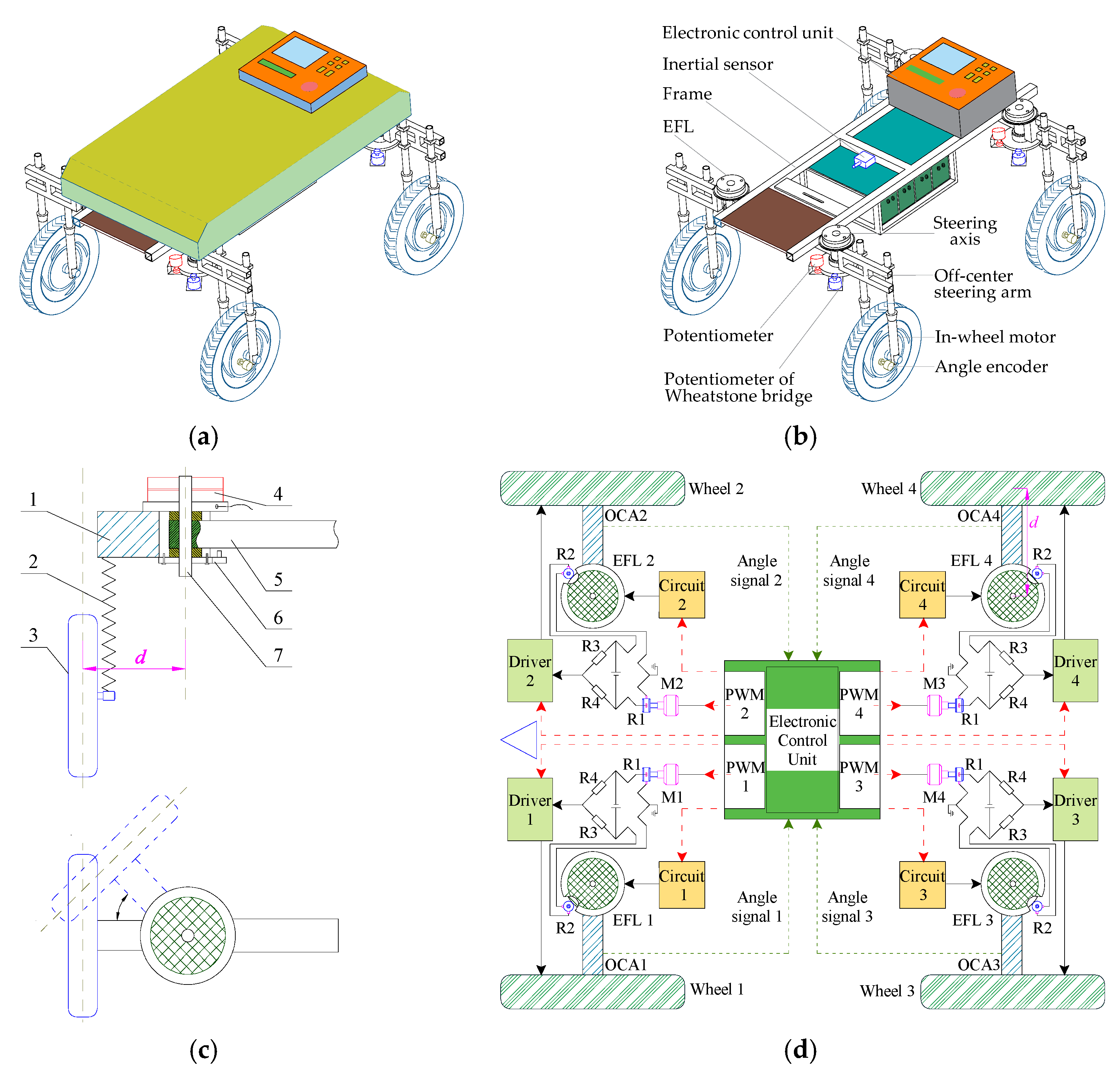
The overall design of the robot, the chassis model, steering mechanism, and electrical system are shown in Figure 2. As presented in Figure 2b, the chassis mainly includes an electronic control unit, multiple sensors, and four off-center steering mechanisms. The simplified model of off-center steering mechanism is shown in Figure 2c. When the robot chassis is at the initial mode, the electromagnetic friction lock (EFL) is locked under DC voltage, and the in-wheel motor is not able to rotate around the off-center axis (Figure 2c). The steering force is derived from the wheels without an additional mechanical structure. The off-center axis leaves a distance d from the wheel motion plane. This minimizes the resistance to the steering structure. When the MMS command is sent by a host computer, the EFL responds under the operation order of the lower computer. The rotation direction of each in-wheel motor is then controlled according to the motion mode requirement.
An illustration of the steering control system for the robot chassis is shown in Figure 2d. In order to transfer the target steering signals to the actuator, a tracking system, based on a Wheatstone bridge circuit, is used [23]. After the steering command is input, the electronic control unit (ECU) directs the M1 and M2 stepper motors, in order to change the resistance of R1 (a multi-turn potentiometer, 2HP-10, SAKAE Company, Tokyo, Japan) of the bridge circuit, which produces a voltage imbalance over the bridge. The output voltage of the bridge drives the in-wheel motors to track the objective steering angle, and the wheels then drive the off-center arms (OCAs) to rotate around the off-center axis, and then the MMS can be performed. A potentiometer R2 (2HP-10) is installed under the off-center axis and rotated by the axis. When the OCAs reach their target angles, the resistance value of R2 reaches the value of R1, and the output voltage of the bridge becomes 0 V. This indicates that a steering tracking motion has been completed and the in-wheel motors are waiting for the next command. The time required for the MMS is determined by the speed of the stepper motor. Thus, the MMS performance is mainly affected by controlling the driving voltage of the EFL and stepper motor speed.
Previous studies demonstrated that the effect of the MMS is improved using a fixed EFL driving voltage [24]. However, the impacts of the driving voltage of EFL and stepper motor speed on the four-wheel-steering MMS have not been verified. Therefore, the following section explores the four-wheel-steering MMS performance through experiments, and then searches for the optimal control parameters combination.

2.2. Motion Mode Switching Model

2.2.1. Ackermann Steering Model

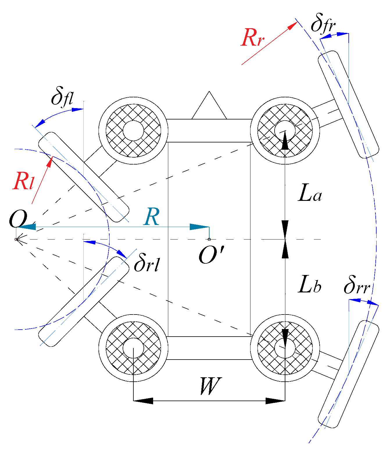
The four-wheel-steering mode is switched in situ. As shown in Figure 3, to ensure smooth steering, the steering centers of all wheels should converge at one point during the MMS process, based on the Ackermann steering principle. When the wheels are configured to turn left, the turning radius of the right wheels Rr is greater than that of the left wheels Rl. Therefore, the steering angles of he right wheels are smaller than those of the left wheels. Additionlly, the steering angle and OCA angular velocity of each wheel have to maintain the relationship shown in Equations (1) and (2).
c t g δ f l c t g δ f r = W L a
c t g δ r l c t g δ r r = W L b

2.2.2. Steering Lock Model

The locking voltage of the EFL Vl ranges between 0 V and 24 V. The friction moment Mz of EFL and Vl is given by Equation (3) [23].
M Z = μ R m F d ( N 1 )
F d = B 2 S 8 π × 10 - 7
B = 0.4 π I W ( 1 + σ ) ( N 1 ) δ
where μ is friction coefficient, Rm is radius of friction surface (m), Fd is magnetic adhesion (N), N is number of friction plates, B is magnetic induction (T), S is cross sectional area of the magnetic pole (m2), I is exciting current (A), W is number of windings, σ is magnetic leakage factor, and δ is air gap width (m).
When the structure of EFL is fixed, the friction moment is only related to the exciting current I, and the current is determined by the locking voltage Vl. Locking voltage is the key factor affecting steering force. Additionally, it could be deduced from the pre-experiment that, when Vl was higher than 8 V, the OCA could not steer to the target position due to the high Mz. When Vl was lower than 2 V, the steering angle of the OCA had a large overshoot. Thus, in order to ensure the steering accuracy, the locking voltage of the EFL Vl should be in the range of 2 to 8 V.

2.2.3. Mechanical Model of the Chassis

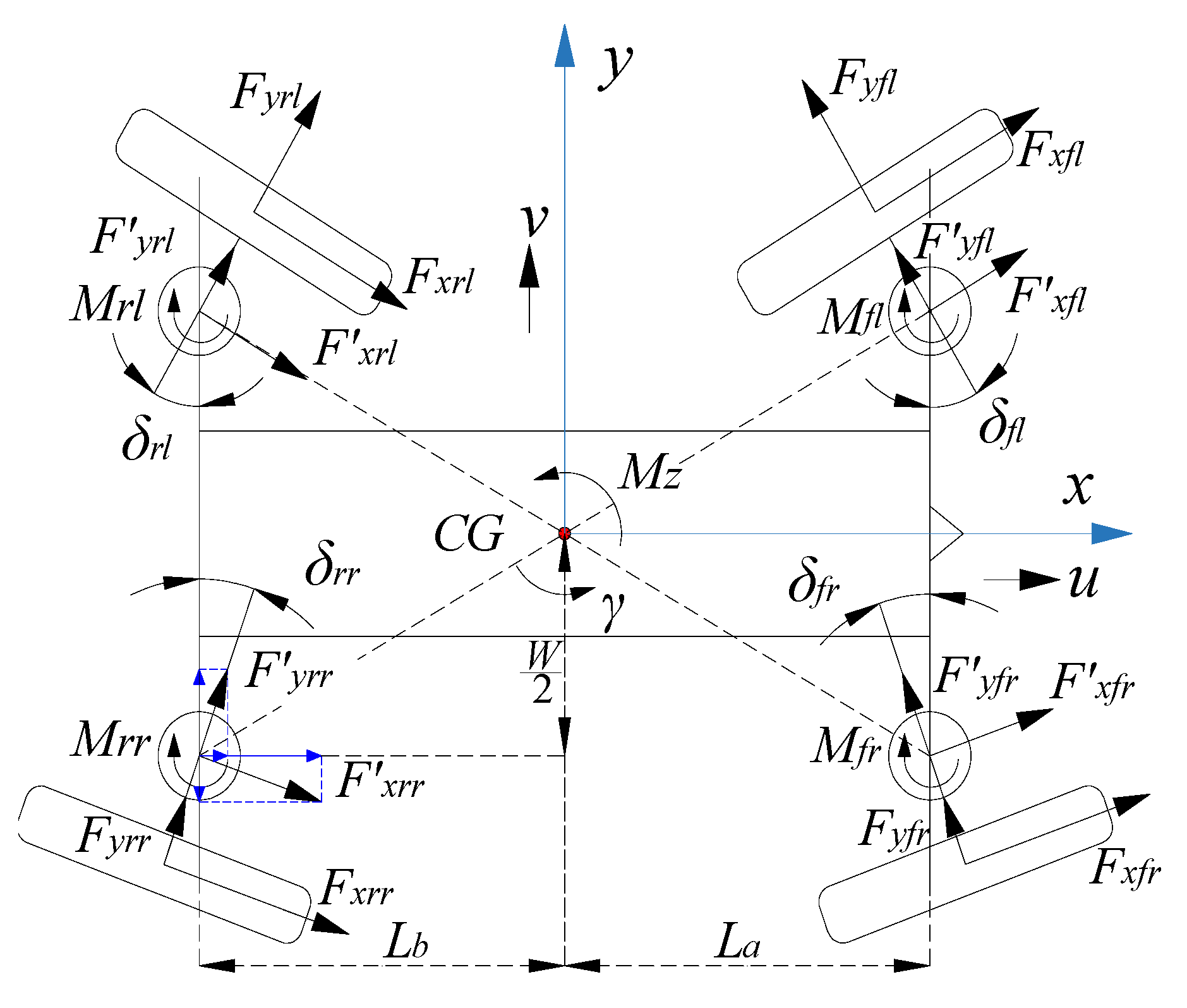
A simplified dynamics model was used for the chassis MMS (Figure 4). It was assumed that there was no suspension system effect, nor air resistance. The changes in the chassis longitudinal speed were also ignored. Only lateral motion (y-axis), longitudinal motion (x-axis) and yaw motion (rotation around the z-axis) of the chassis, were considered. The centroid (CG) of the chassis was considered to be the origin of the coordinate system. The wheels on the right had to have a smaller steering angle because they travel on a longer arc with a larger radius than the left wheels when the wheels are configured to turn left. The restrictions on the wheel angles are expressed in Equation (6).
{ δ f l = δ r l δ f r = δ r r δ f l > δ f r
In Figure 4, when Fxi and Fyi are transferred to the off-center axis, F′xi, F′yi and MZi are formed. Thus, in this dynamic model, the kinetic equations of the lateral, longitudinal and yaw motion of the robot chassis are expressed in Equations (7)–(9), respectively.
F x f l cos δ f l F y f l sin δ f l + F x f r cos δ f r F y f r sin δ f r + F x r l cos δ r l + F y r l sin δ r l + F x r r cos δ r r + F y r r sin δ r r = F X
F x f l sin δ f l + F y f l cos δ f l + F x f r sin δ f r + F y f r cos δ f r + F x r l sin δ r l F y r l cos δ r l + F x r r sin δ r r F y r r cos δ r r = F Y
i = 1 4 M Z i + W 2 [ ( F x f r cos δ f r F y f r sin δ f r + F x r r cos δ r r + F y r r sin δ r r ) ( F x f l cos δ f l F y f l sin δ f l + F x r l cos δ r l + F y r l sin δ r l ) ] + L a [ ( F x f l sin δ f l + F y f l cos δ f l + F x f r sin δ f r + F y f r cos δ f r ) L b ( F x r l sin δ r l F y r l cos δ r l + F x r r sin δ r r F y r r cos δ r r ) ] = M O
where FX is the resultant force in the x-direction (N), FY represents the resultant force in the y-direction (N), MO denotes the moment of the robot chassis (N·m), F′xi and F′yi respectively represent the forces transferred from Fxi and Fyi to the off-center axis, and MZi denotes friction moment of EFL (N·m).

3. Materials and Methods

3.1. Test Design

Two single factor tests were designed to explore the effect of the locking voltage Vl and speed of the stepper motor ns on the MMS of the chassis. The indexes evaluating MMS effects included the longitudinal force, lateral force, yaw moment of the chassis center point O and average value of maximum steering angle error of the four wheels. The factor Vl was divided into 5 levels (2, 3.5, 5, 6.5 and 8 V). The level of ns was set to 15, 48, 81, 114, 147 and 180 r/min. The four-wheel-steering MMS was divided into three scenarios based on the steering angle value of the left front wheel, 15°, 30° and 45° MMS, as the steering signal sent by the upper computer was the angle of the left front wheel (δfl).
In order to explore the effect of the four-wheel-steering MMS and the optimal combination of the working parameters, a binary quadratic rotation combination test was designed, based on the test bench. Through this test method, it was possible to develop a regression equation and optimize the MMS control parameters. The level of factors and their value codes in the binary quadratic rotation combination test are presented in Table 1.
To study MMS performance on the ground after optimization, verification tests were conducted on the ground. The maximum value of longitudinal acceleration, lateral acceleration, yaw velocity, and the average value of the maximum of steering angle error of four OCAs were taken as evaluating indexes, denoted as Y1, Y2, Y3, and Y4, respectively.

3.2. Experiment Device and Instrument

The experiment conducted was based on the self-made test bench. Four force sensors (TJL-1, 0~500 N, Tianguang Sensor Company, Bengbu, China) were used to obtain the longitudinal and lateral driving forces of the chassis. Four precision multi-turn potentiometers (22HP-10, 0–5 kW, Sakae Company, Tokyo, Japan) were used to detect the steering angle of each wheel. An inertial sensor (WT61C232, Wiite Intelligent Technology Company, Shenzhen, China) was used to measure the accelerations in the ground test. A data acquisition card (USB2852, Altay Technology Company, Beijing, China) and an industrial personal computer (610H, Advantech Technology Company, Beijing, China) were used to obtain the data. The response surface and contour graph of the comprehensive evaluation index of MMS by locking voltage and speed of stepper motor, were obtained using software Design-Expert 12 (Stat-Ease, Inc., Minneapolis, MN, USA).

3.3. Test Method

The test bench had four independent turntables, that supported the drive wheels of the robot chassis, as shown in Figure 5a–c. Each turntable had four small supporting rollers, a motor to drive the turntable, and a friction brake for the motor rotation. The center of the turntable was on the same vertical axis as the corresponding off-center axis. When the chassis was placed on the test bench (Figure 5b), a small gap of about 0.02 m was left between the chassis frame and the top platform of the test bench. By driving the wheels of the chassis, controlling the speed of the turntables and adjusting the braking moment, the test bench could be used to simulate all the modes of motion and steering movements, under different driving conditions. In addition, four force sensors were installed on the frame of the chassis. The outer side of each sensor was restricted by a spacing hole drilled on the top platform of the test bench, and used to measure the interaction forces between the chassis and the test bench. Sensors 5 and 6 measured the forces in the forward direction, while the measuring directions of force sensors 7 and 8 were perpendicular to the forward direction of the chassis. The yaw moment of the chassis was calculated according to the force sensor value and the vertical distance from the center to each force direction. Due to the fact that the MMS test had to be conducted in situ, all the turntables were fixed through a brake disc and could not be rotated. Thus, the turntable was still relative to the ground. Before the beginning of the test, we ensured the acquisition system was ready to collect data from the force sensors and steering angle sensors. At the initial time, the chassis was in standby mode. After the MMS command was sent to the lower computer, each stepper motor rotated according to the switching requirement of MMS. After one test was completed, the chassis was controlled to return to the initial mode for the next test.
In verification tests, the robot chassis was fixed in situ, and four OCAs were driven to achieve the commanded steering angles. The tests were divided into two groups: the one was conducted under optimized control parameters, and the other one was carried out under unoptimized parameters. Each test group was repeated three times in order to obtain the average value.

3.4. Multi-Index Comprehensive Evaluation

As there were four evaluation indexes, it was necessary to use a comprehensive evaluation method to find out the weight of index. Methods for finding weights can be divided into subjective method and objective method. Subjective weights are determined only by the preference of decision makers. Objective weights are determined by solving mathematical models without the decision maker’s preferences, for example, the entropy method, principal element analysis, multiple objective programming, etc. Compared to subjective weight-assigning methods, the entropy method can eliminate the errors caused by human factors [25]. The index weight by the entropy method is determined according to the information provided by the observation value of each index [26]. Compared with other objective methods, the entropy method has simple operation steps, which can also reduce the error caused by complex processes. This study only dealt with a simple weight distribution problem, and the entropy method was the best choice for comprehensive evaluation. Thus, the longitudinal force, lateral force and yaw moment were unified as a comprehensive evaluation index YHk (k = 1, 2, or 3) through the entropy method. It was assumed that there were m (m = 4) combinations of the test and n (n = 4) indexes. λij was introduced to denote the j indexes of the i test group (i represents 1, 2, …, and n, j denotes 1, 2, …, and m). The process of comprehensive evaluation is summarized as follows.
(1)
Standardization of the index
Due to the fact that smaller values of all factors led to a better evaluation index in this study, a negative index equation was used:
λ i j = max { λ 1 j , , λ n j } λ i j max { λ 1 j , , λ n j } min { λ 1 j , , λ n j }
(2)
The weight of each index was computed as:
P i j = λ i j / ( i = 1 n λ i j )
(3)
The entropy value of the j index was given by:
e j = k i = 1 n p i j ln ( p i j )   ( k = 1 / ln ( n ) )
(4)
The information entropy redundancy of the j index was expressed as:
d j = 1 e j
(5)
The weight of the j index was computed as:
w j = d j / ( j = 1 m d j )
(6)
The comprehensive evaluation index was expressed as:
s i = j = 1 n w j p i j
According to this evaluation procedure, the comprehensive evaluation index value could be obtained (cf. Equation (15)). The closer the comprehensive evaluation index was to 1, the better the performance of the MMS.

4. Results Analysis

4.1. Single Factor Test Results

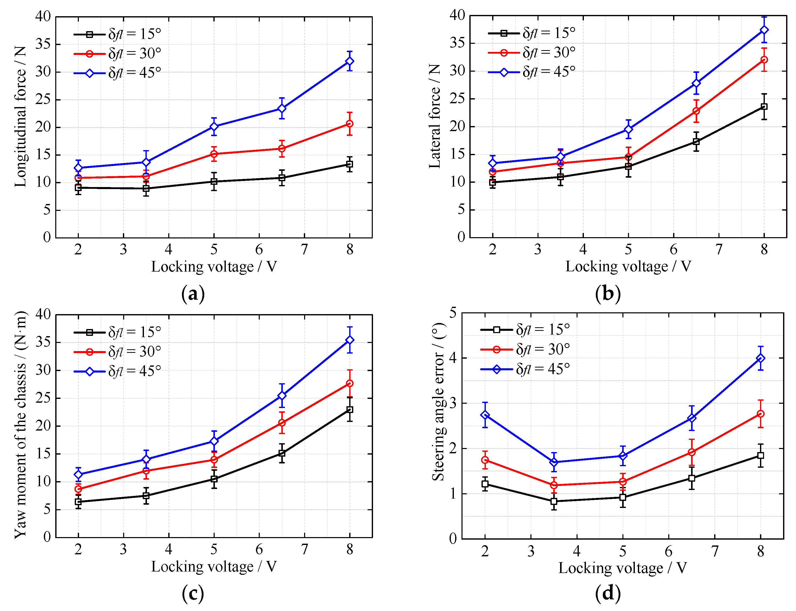
The final value of each index, deduced from the single factor test results of Section 3, are shown in Figure 6. Under three steering angle scenarios, with the increase of the locking voltage, the longitudinal driving force, lateral force and yaw moment of the chassis gradually increased (Figure 6a–c). However, the angle errors of the OCA all first decreased, then increased (Figure 6d). According to Equation (3), as the locking voltage increased, the transmission force of the EFL increased, which resulted in increasing the longitudinal force, lateral force and yaw moment. When the locking voltage was lower than 3.5 V, the force of the in-wheel motor was not enough to drive the OCA, resulting in large steering angle errors. When the locking voltage was higher than 6.5 V, the OCA was difficult to rotate, which also resulted in large errors. Additionally, under the same locking voltage, all indexes grew with the increase of steering angle. It could be inferred that as the steering angle increased, the accuracy of the MMS declined under the same locking voltage.
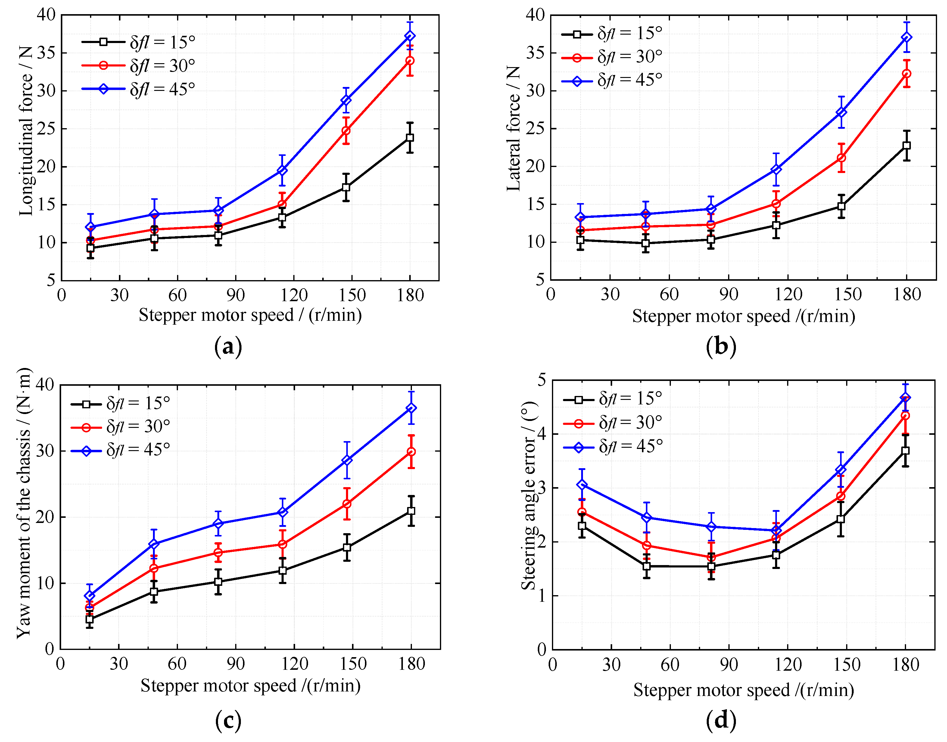
The impacts of the stepper motor speed on each index are shown in Figure 7. Under three steering angle scenarios, with increase of the stepper motor speed, the longitudinal force and lateral force slightly increased up to the speed of 114 r·min−1, and then soared. The yaw moment kept an upward tendency while it maintained balance from the speed of 81 r·min−1 to 114 r·min−1 (Figure 7a–c). The angle error first decreased and then increased (Figure 7d). According to Equation (8), the increase of the stepper motor speed would add to the driving force of the in-wheel motor. Consequently, the longitudinal force, lateral force and yaw moment increased. The in-wheel motor intermittently rotated when the speed of the stepper motor was smaller 48 r·min−1, which resulted in a large angle error. When the speed of the stepper motor was higher than 114 r·min−1, the driving voltage of the in-wheel motor increased, which made the OCA rotate sharply and increased the angle error. Therefore, the angle error also demonstrated a trend of increasing after decreasing. All indexes increased with the increase of steering angle under the same stepper motor speed. It was clear that the accuracy of the chassis MMS reduced with increase in steering angle.

4.2. Combination Test Results

4.2.1. Analysis of Comprehensive Evaluation Index

Based on the test design in Table 1, thirteen test combinations existed. The test results are presented in Table 2. Table 2 shows the calculation results of comprehensive indicators under the conditions of 15°, 30° and 45°.
The variance analyses for the regression model are presented in Table 3. At the 0.05 tested level, the regression model of the four-wheel-steering MMS under the 15° steering scenario was significant (p < 0.05), while it was highly significant (p < 0.01) under 30° and 45°. The effect of each equation item was also significant (p < 0.05). Under the 15° scenario, the most significant effects were the quadratic term of locking voltage and the primary term of motor speed. At 30° and 45°, the quadratic terms of the locking voltage and speed of the stepper motor had extremely significant effects. The locking voltage, speed of the stepper motor and their interaction highly affected the MMS. The minimum determination coefficient of the regression model was 0.9116, and the minimum adjusted determination coefficient was 0.8485. The values of lack of fit were greater than 0.05, and the values of the signal-to-noise ratio were greater than 4 in the three cases. These characteristics suggested that the regression model was reasonable and efficient.
The indexes were regressed using software Design-Expert 12 (Stat-Ease, Inc., Minneapolis, MN, USA). The regression model of the comprehensive evaluation index was obtained:
Y H 1 = 0.0099 + 0.0619 x 1 + 0.0002 x 2 + 0.0002 x 1 x 2 0.0092 x 1 2 0.00009 x 2 2
Y H 2 = 0.0546 + 0.0728 x 1 + 0.0008 x 2 + 0.0001 x 1 x 2 0.0096 x 1 2 0.00001 x 2 2
Y H 3 = 0.0991 + 0.0570 x 1 + 0.0011 x 2 + 0.0002 x 1 x 2 0.0069 x 1 2 0.00001 x 2 2

4.2.2. Response Surface Analysis

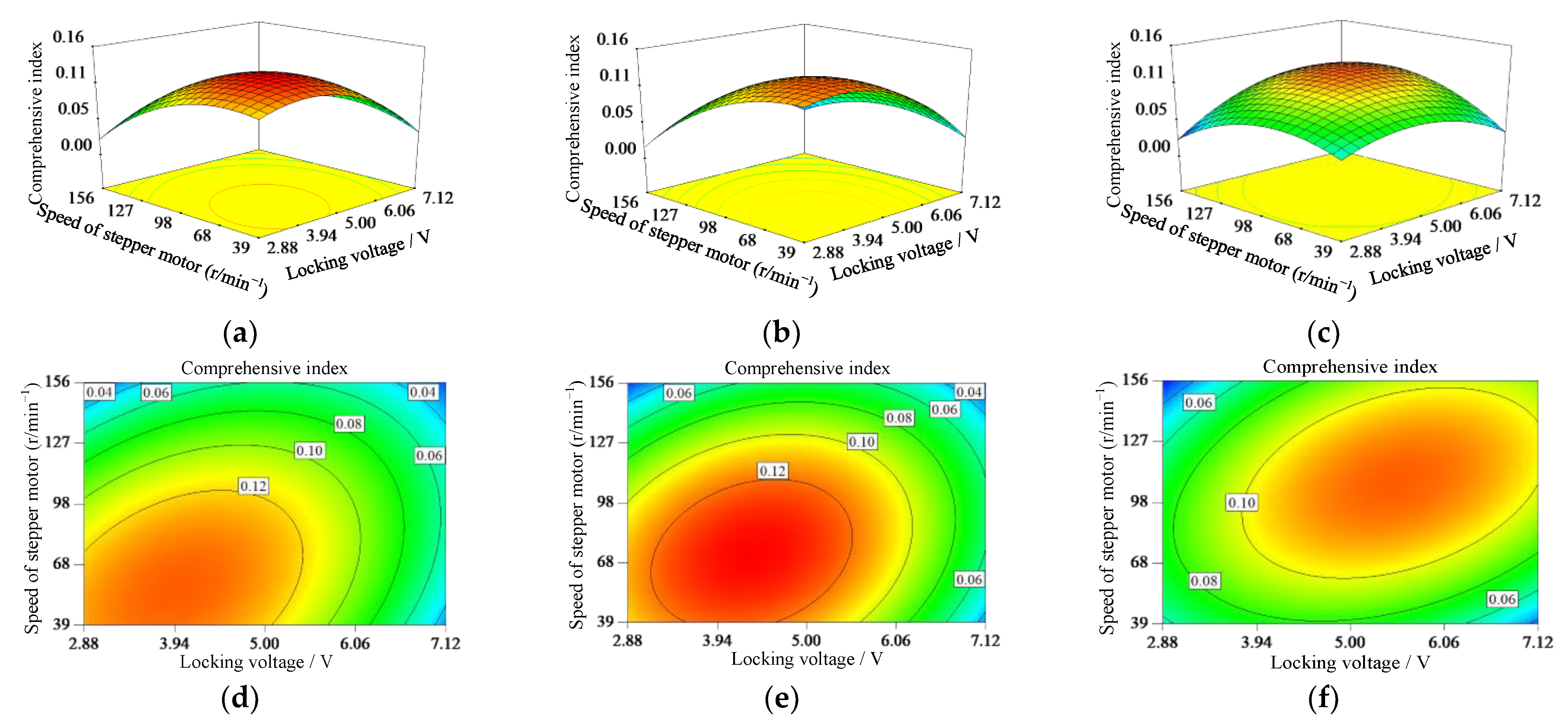
Figure 8 shows the influence of locking voltage and speed of stepper motor on comprehensive evaluation index. From Figure 8a–c, when the locking voltage and speed of stepper motor increased, the response surfaces all appeared as a convex surface. The comprehensive evaluation index reached its peak value. The peak value of the response surface was located in the test factor value scope, and the best MMS performance could be obtained.
It can be seen from the comparison of Figure 8d–f that the locking voltage and speed of the stepper motor corresponding to the peak value of curved surface rose with increase of steering angle. The maximum value of comprehensive evaluation was different in the three steering scenarios. This indicated that the optimal locking voltage and speed of the stepper motor should be dynamically adjusted in order to achieve smooth switching.
Considering the regression model of the comprehensive evaluation index as the objective function, and the range of the factors as constraint condition, the optimal combination of the parameters was obtained using the optimization module of Design-Expert 12. The best combination of the stepper motor speed and the locking voltage was 56 r·min−1 and 3.96 V for 15° MMS, 72 r·min−1 and 4.35 V for 30° MMS, and 107 r·min−1 and 5.50 V for 45° MMS, respectively. In these combinations, the robot chassis was expected to achieve the best MMS performance.

4.3. Verification Test Results

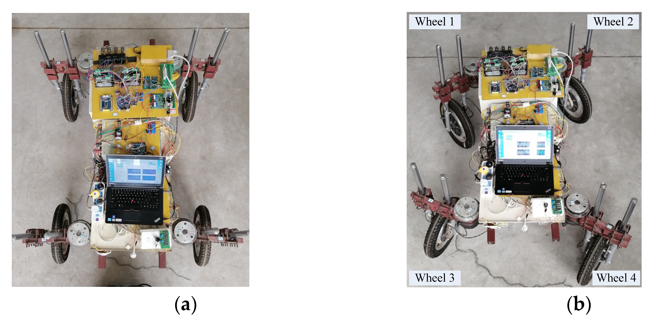
Under the optimal parameters, a test was conducted on the ground in order to verify the optimization results (Figure 9). The test results are presented in Table 4. The maximum value of longitudinal acceleration, lateral acceleration, yaw velocity, and the average value of the maximum of steering angle error of the four OCAs were denoted as Y1, Y2, Y3, and Y4, respectively. In different steering angle scenarios, the minimum variation between the optimized and unoptimized was 27.5% of the steering angle error occurred in the 45° scene. The maximum variation was 49.5% of the lateral acceleration in the 30° scene.
In this paper, the curves of longitudinal acceleration, lateral acceleration, yaw rate, and steering angle error under the 30° steering scenario are presented as an example to illustrate the four-wheel-steering MMS process. Figure 10 presents the angle change of each OCA during the four-wheel-steering MMS. It can be seen that there was an obvious difference between the optimized scheme and the unoptimized scheme in the angle response. When the actual steering angle approached the target angle, its fluctuation in the optimized scheme was smaller than that of the unoptimized scheme. The steering angle of the optimized scheme reached the balance position in almost 4.6 s, while it reached the balance position in almost 5.5 s in the unoptimized scheme. In addition, compared with the unoptimized scheme, there was no obvious steering angle error difference in the optimized scheme for wheel 1 (Figure 10a). However, the angle error of the other three wheels after optimization was less than that of the unoptimized scheme. The maximum angle errors were, respectively, 1.98°and 0.85° in the unoptimized and optimized schemes, which occurred in wheels 4 (Figure 10a) and 2 (Figure 10b), respectively. After optimization, each OCA steering angle reached the balance position more rapidly, and the error was smaller than that before optimization. Thus, it could be seen that the steering performance had been optimized.
Figure 11a shows the change of longitudinal and lateral acceleration during the four-wheel-steering MMS. It can be observed that the longitudinal and lateral accelerations reduced after optimization. The maximum longitudinal and lateral accelerations were, respectively, 0.003 m·s−2 and 0.005 m·s−2, while the maximum longitudinal and transverse accelerations before optimization were 0.009 m·s−2 and 0.007 m·s−2, respectively. After optimization, the fluctuation amplitude of acceleration significantly reduced. Thus, it can be deduced that the longitudinal and lateral stabilities of the chassis had improved. Figure 11b presents the change of chassis yaw rate during MMS. It can be seen that the yaw rate significantly declined after parameter optimization. Before optimization, the maximum yaw rate reached 0.07 rad·s−1, while it was only 0.04 rad·s−1 after optimization. The results demonstrated that the performance of MMS was promoted after parameter optimization, which was more conducive to the real task. The smaller the yaw rate, the more stable the MMS process. In summary, the test indicated that the MMS performance improved after optimization. Therefore, the proposed method was feasible and efficient.

5. Discussion

Studying motion control technology is critical to the application of agricultural mobile robots. Several structures, similar to the proposed robot, exist, for example, the agricultural robotic vehicle for navigation tasks under off-road conditions [27], the thorvald II agricultural robotic system [28] and the robot for in-row weed control of vegetables [29]. However, these studies all used complex mechanical structures for steering control. In this paper, the off-center steering structure with the combination of drive and steering system is expected to improve the steering and control form of the electric wheel mobile platform, which is one of the main features of this study. The optimal control parameters obtained in this study are also transferable to the later structural optimization of the robot chassis, reducing the chassis response adjustment time, and improving work efficiency.
In order to perform MMS control parameter optimization, a bench test, multi-index comprehensive evaluation method and road test verification were simultaneously used. Several studies for testing the mechanical properties of agricultural wheeled machinery through the test-bench exist. For instance, Wen et al. [30] applied a drum-type test bench for designing tractor accelerated structure tests. Zhang et al. [31] designed a four-wheel drive powertrain bench. Parczewski and Wnek [32] developed a vehicle test bench equipped with a specially made measuring rocker arm. The proposed method is consistent with these studies. It is important to mention that this study detected the force, yaw moment and angle of the robot chassis through a novel test-bench, in order to comprehensively evaluate the switching performance of MMS, which is also a novel feature, compared with the existing studies.
The overall performance of the robot chassis was optimal when the locking voltage and stepping motor speed were in the range of 3.5~5.5 V. This was due to the following facts: (1) When the locking voltage is lower than the range, the effect of the ground random error on the steering angle is more obvious [33]. In this case, if the speed of the stepping motor is at a low level, the ground resistance makes it difficult to reach the target angle. If the motor speed is at a high level, the angle overshoot is bound to increase. (2) When the locking voltage is higher than the range, the effect of the ground random error on the chassis stress is more obvious. In this case, if the speed of the stepping motor is at a low level, the in-wheel motor only rotates when the voltage difference of the bridge reaches a certain degree. The instantaneous current of the motor is acute at the moment of starting, and the torque fluctuates greatly, creating intermittent rotation, which can easily cause unbalanced stress on the chassis. If the motor speed is at a high level, the average current of the in-wheel motor is large during the startup and rotation, and the possibility of force imbalance is also high.
In the verification test, the minimum variation of the steering angle error was 27.5%, which was abnormal. This was due to the fact that the optimal stepper motor speed of 56 r·min−1 was relatively low, as shown in Figure 7d. When the speed of the stepper motor was lower than 81 r·min−1, the steering angle error maintained a higher value. The relatively low speed of the stepper motor caused the chassis stress to fluctuate greatly, which resulted in a large error. As the performance of the MMS was determined by the comprehensive evaluation index, the mentioned minimum variation of the sub-index was allowed. These variations were in the acceptable range, and, thus, the optimal parameters combination was reasonable.
Nevertheless, the tests conducted in this paper are not sufficient, and the influence law of road factors in MMS should be deeply explored. In future work, we aim at expanding the experimental study. Finally, the change law of the chassis during different road motion switching modes is also of interest to us.

6. Conclusions

This paper proposes a performance optimization methodology of a novel wheeled mobile robot used for facility agriculture. The key factors affecting the MMS performance were first revealed by analysis. In order to achieve control parameters optimization, a bench test was performed to study the best combination of locking voltage of EFL and stepper motor speed. An entropy method was introduced in order to evaluate the comprehensive effect of four different indexes. To explore the effect of each control parameter, a binary quadratic rotation combination test was designed. A road test was finally performed in order to verify the optimal control parameters combination. The bench test results showed that the locking voltage and speed of the stepper motor highly affected the comprehensive index (p < 0.05). A locking voltage of 3.96 V with a stepper motor speed of 56 r·min−1 was the optimal combination for 15° four-wheel steering MMS, while the optimal parameters under 30° were 4.35 V and 72 r·min−1, and 5.50 V and 107 r·min−1 under 45°, respectively. The road test results demonstrated that the MMS process of the robot chassis was smooth and stable. The proposed method was feasible, efficient and ultimately verified. In future work, the performance of the MMS during different roads will be deeply explored. This study can provide a reference for experimental studies on agricultural wheeled mobile robots.

Author Contributions

Conceptualization, J.Q. and K.G.; methodology, J.Q.; software, H.L. and Z.Z.; validation, H.L. and Z.Z.; formal analysis, J.Q. and K.G.; investigation, H.L. and Z.Z.; resources, H.L. and Z.Z.; data curation, H.L. and Z.Z.; writing—original draft preparation, J.Q.; writing—review and editing, X.X.; visualization, J.Q.; supervision, X.X.; project administration, J.Q., X.X. and R.Z.; funding acquisition, J.Q., X.X. and R.Z. All authors have read and agreed to the published version of the manuscript.

Funding

This research was funded by the Jiangsu Provincial Natural Science Foundation [grant number BK20210823]; the Jiangsu agricultural science and technology innovation fund [grant number CX (21) 3153]; Yangzhou University Interdisciplinary Research Foundation for Crop Science Discipline of Targeted Support (yzuxk202007); Jiangsu Modern Agricultural Machinery Equipment and Technology Demonstration and Promotion Project (NJ2021-16); High-end Talent Support Program of Yangzhou University.

Data Availability Statement

Not applicable.

Conflicts of Interest

The authors declare no conflict of interest.

References

  1. Zhang, J.; Liu, L.; Zhao, Y.; Li, H.; Lian, Y.; Zhang, Z.; Huang, C.; Du, X. Development of a high-resolution emission inventory of agricultural machinery with a novel methodology: A case study for Yangtze River Delta region. Environ. Pollut. 2020, 266, 115075. [Google Scholar] [CrossRef] [PubMed]
  2. Balafoutis, A.; Beck, B.; Fountas, S.; Vangeyte, J.; van der Wal, T.; Soto, I.; Gomez-Barbero, M.; Barnes, A.; Eory, V. Precision agriculture technologies positively contributing to GHG emissions mitigation, farm productivity and economics. Sustainability 2017, 9, 1339. [Google Scholar] [CrossRef] [Green Version]
  3. Mantoam, E.J.; Angnes, G.; Mekonnen, M.M.; Romanelli, T.L. Energy, carbon and water footprints on agricultural machinery. Biosyst. Eng. 2020, 198, 304–322. [Google Scholar] [CrossRef]
  4. Lovarelli, D.; Bacenetti, J. Exhaust gases emissions from agricultural tractors: State of the art and future perspectives for machinery operators. Biosyst. Eng. 2019, 186, 204–213. [Google Scholar] [CrossRef]
  5. Gonzalez-de-Soto, M.; Emmi, L.; Benavides, C.; Garcia, I.; Gonzalez-de-Santos, P. Reducing air pollution with hybrid-powered robotic tractors for precision agriculture. Biosyst. Eng. 2016, 143, 79–94. [Google Scholar] [CrossRef]
  6. Bechar, A.; Vigneault, C. Agricultural robots for field operations: Concepts and components. Biosyst. Eng. 2016, 149, 94–111. [Google Scholar] [CrossRef]
  7. Chang, C.L.; Song, G.B.; Lin, K.M. Two-stage guidance control scheme for high- precision straight-line navigation of a four-wheeled planting robot in a greenhouse. Trans. ASABE 2016, 59, 1193–1204. [Google Scholar] [CrossRef]
  8. Reina, G.; Milella, A.; Rouveure, R.; Nielsen, M.; Worst, R.; Blas, M.R. Ambient awareness for agricultural robotic vehicles. Biosyst. Eng. 2016, 146, 114–132. [Google Scholar] [CrossRef]
  9. Lombardi, G.V.; Berni, R. Renewable energy in agriculture: Farmers willingness-to-pay for a photovoltaic electric farm tractor. J. Clean. Prod. 2021, 313, 127520. [Google Scholar] [CrossRef]
  10. Jones, M.H.; Bell, J.; Dredge, D.; Seabright, M.; Scarfe, A.; Duke, M.; MacDonald, B. Design and testing of a heavy-duty platform for autonomous navigation in kiwifruit orchards. Biosyst. Eng. 2019, 187, 129–146. [Google Scholar] [CrossRef]
  11. Wu, X.; Zhang, Y.; Zou, T.; Zhao, L.; Lou, P.; Yin, Z. Coordinated path tracking of two vision-guided tractors for heavy-duty robotic vehicles. Robot Cim.-Int. Manuf. 2018, 53, 93–107. [Google Scholar] [CrossRef]
  12. Mahmud, M.S.A.; Abidin, M.S.Z.; Mohamed, Z.; Rahman, M.K.I.A.; Iida, M. Multi- objective path planner for an agricultural mobile robot in a virtual greenhouse environment. Comput. Electron. Agric. 2019, 157, 488–499. [Google Scholar] [CrossRef]
  13. Gorjian, S.; Ebadi, H.; Trommsdorff, M.; Sharon, H.; Demant, M.; Schindele, S. The advent of modern solar-powered electric agricultural machinery: A solution for sustainable farm operations. J. Clean. Prod. 2021, 292, 126030. [Google Scholar] [CrossRef]
  14. Zhang, Y.; Ni, J.; Tian, H.; Wu, W.; Hu, J. Integrated robust dynamics control of all-wheel-independently-actuated unmanned ground vehicle in diagonal steering. Mech. Syst. Signal Process. 2022, 164, 108263. [Google Scholar] [CrossRef]
  15. Liu, X.; Wang, W.; Li, X.; Liu, F.; He, Z.; Yao, Y.; Ruan, H.; Zhang, T. MPC-based high-speed trajectory tracking for 4WIS robot. ISA Transact. 2022, 123, 413–424. [Google Scholar] [CrossRef] [PubMed]
  16. Raikwar, S.; Fehrmann, J.; Herlitzius, T. Navigation and control development for a four-wheel-steered mobile orchard robot using model-based design. Comput. Electron. Agric. 2022, 202, 107410. [Google Scholar] [CrossRef]
  17. Qiu, Q.; Fan, Z.; Meng, Z.; Zhang, Q.; Cong, Y.; Li, B.; Wang, N.; Zhao, C. Extended Ackerman Steering Principle for the coordinated movement control of a four wheel drive agricultural mobile robot. Comput. Electron. Agric. 2018, 152, 40–50. [Google Scholar] [CrossRef]
  18. Zhu, J.; Wang, Z.; Zhang, L.; Dorrell, D.G. Braking/steering coordination control for in-wheel motor drive electric vehicles based on nonlinear model predictive control. Mech. Mach. Theory 2019, 142, 103586. [Google Scholar] [CrossRef]
  19. Gao, Z.; Zhang, D.; Zhu, S.; Feng, J.-E. Distributed active disturbance rejection control for Ackermann steering of a four-in-wheel motor drive vehicle with deception attacks on controller area networks. Inf. Sci. 2020, 540, 370–389. [Google Scholar] [CrossRef]
  20. Ghobadpour, A.; Boulon, L.; Mousazadeh, H.; Malvajerdi, A.S.; Rafiee, S. Asm and A. Sr. State of the art of autonomous agricultural off-road vehicles driven by renewable energy systems. Energy Procedia 2019, 162, 4–13. [Google Scholar] [CrossRef]
  21. Song, S.; Qu, J.; Li, Y.; Zhou, W.; Guo, K. Fuzzy control method for a steering system consisting of a four-wheel individual steering and four-wheel individual drive electric chassis. J. Int. Fuzzy Syst. 2016, 31, 2941–2948. [Google Scholar] [CrossRef]
  22. Qu, J.; Guo, K.; Zhang, Z.; Song, S.; Li, Y. Coupling control strategy and experiments for motion mode switching of a novel electric chassis. Appl. Sci. 2020, 10, 701. [Google Scholar] [CrossRef] [Green Version]
  23. Song, S.; Guo, K. Automatic tracking steering system for off-centered flexible chassis steering axis based on fuzzy-PI composite control. J. Int. Fuzzy Syst. 2018, 35, 187–195. [Google Scholar] [CrossRef]
  24. Song, S.; Li, Y.; Qu, J.; Zhou, W.; Guo, K. Design and test of flexible chassis automatic tracking steering system. Int. J. Agric. Biol. Eng. 2017, 10, 45–54. [Google Scholar] [CrossRef] [Green Version]
  25. Lotfi, H.F.; Fallahnejad, R. Imprecise Shannon’s Entropy and Multi Attribute Decision Making. Entropy 2010, 12, 53–62. [Google Scholar] [CrossRef] [Green Version]
  26. Shannon, C.E. A mathematical theory of communication. Bell Syst. Tech. J. 1948, 27, 379–423. [Google Scholar] [CrossRef] [Green Version]
  27. Tu, X.; Gai, J.; Tang, L. Robust navigation control of a 4WD/4WS agricultural robotic vehicle. Comput. Electron. Agric. 2019, 164, 104892. [Google Scholar] [CrossRef]
  28. Grimstad, L.; From, P. The Thorvald II agricultural robotic system. Robotics 2017, 6, 24. [Google Scholar] [CrossRef] [Green Version]
  29. Utstumo, T.; Urdal, F.; Brevik, A.; Dorum, J.; Netland, J.; Overskeid, O.; Berge, T.W.; Gravdahl, J.T. Robotic in-row weed control in vegetables. Comput. Electron. Agric. 2018, 154, 36–45. [Google Scholar] [CrossRef]
  30. Wen, C.; Xie, B.; Song, Z.; Yang, Z.; Dong, N.; Han, J.; Yang, Q.; Liu, J. Methodology for designing tractor accelerated structure tests for an indoor drum-type test bench. Biosyst. Eng. 2021, 205, 1–26. [Google Scholar] [CrossRef]
  31. Zhang, W.; Zhang, H.; Shi, H. Study on energy flow test of electric vehicle based on four-wheel drive powertrain bench. In Proceedings of the 2020 6th International Conference on Energy, Environment and Materials Science, EEMS 2020, Hulun Buir, China, 28–30 August 2020; IOP Publishing Ltd.: Bristol, UK, 2020. [Google Scholar] [CrossRef]
  32. Parczewski, K.; Wnek, H. Influence of clearance on the rocker arm pin on the steerability and stability of the vehicle motion. Energies 2021, 14, 7827. [Google Scholar] [CrossRef]
  33. Ko, M.H.; Ryuh, B.S.; Kim, K.C.; Suprem, A.; Mahalik, N.P. Autonomous greenhouse mobile robot driving strategies from system integration perspective: Review and application. IEEE/ASME Trans. Mechatron. 2015, 20, 1705–1716. [Google Scholar] [CrossRef]
Figure 1. Diagram of the motion modes for the robot chassis.
Agronomy 12 02655 g001
Figure 2. Diagram of system structure for the robot chassis: (a) Overall design; (b) Chassis model; (c) Simplified model of off-center steering mechanism; (d) Electrical system diagram. 1. OCA; 2. Suspension; 3. In-wheel motor; 4. EFL; 5. The chassis frame; 6. Precision multi-turn potentiometer (R2 in (b); 7. Off-center axis. Note: M1 to M4 denotes the stepper motor; R1, R3, and R4 represent the potentiometer of the bridge circuit; R2 represent precision multi-turn potentiometer.
Agronomy 12 02655 g002
Figure 3. Illustration of the four-wheel-steering MMS for the robot chassis. O is the turning radius center; O′ is the center of the chassis; R is the turning radius of chassis centroid (m); Rl is the turning radius of the left wheels (m); Rr is the turning radius of the right wheels (m); La and Lb denote the distances from the front and rear off-center axis to OO′, respectively (m); W is the distance between the left and right off-center axis (m); δfl, δfr, δrl, δrr denote the steering angles of the left front, right front, left rear and right rear wheel, respectively (rad).
Agronomy 12 02655 g003
Figure 4. Simplified free body diagram of the robot chassis. Fxi is the longitudinal tire force of each wheel (N), Fyi represents the lateral tire force (N), MZ denotes the yaw moment generated by the four wheels (N·m), CG is the center of chassis gravity, and γ is the yaw rate (deg·s−1). i = 1(fl), 2(fr), 3(rl), 4(rr) denote the left front, right front, left rear and right rear wheel of the robot chassis, respectively.
Agronomy 12 02655 g004
Figure 5. Diagram of experimentation: (a) Structure diagram of test bench; (b) Diagram of bench test; (c) Photo of test bench. 1. Longitudinal limiting groove; 2. Lateral limiting groove; 3. Horizontal turntable; 4. Turntable driving motor; 5–8. Force sensor installation position; 9–10. Angle sensor installation position.
Agronomy 12 02655 g005
Figure 6. Impact of the locking voltage on (a) Longitudinal force; (b) Lateral force; (c) Yaw moment; (d) Steering errors.
Agronomy 12 02655 g006
Figure 7. Impact of the stepper motor speed on (a) Longitudinal force; (b) Lateral force; (c) Yaw moment; (d) Steering errors.
Agronomy 12 02655 g007
Figure 8. Influence of locking voltage and speed of stepper motor on comprehensive evaluation index: (a) Response surface of 15° MMS; (b) Response surface of 30° MMS; (c) Response surface of 45° MMS; (d) Contour plot of 15° MMS; (e) Contour plot of 30° MMS; (f) Contour plot of 45° MMS.
Agronomy 12 02655 g008
Figure 9. Test scenes of the four-wheel-steering MMS: (a) Preparation mode; (b) Four-wheel steering.
Agronomy 12 02655 g009
Figure 10. Steering angle curves of four OCAs: (a) Angle changes for wheel 1 and 2, (b) Angle changes for wheel 3 and 4.
Agronomy 12 02655 g010
Figure 11. The centroid acceleration and yaw rate changes of the chassis during MMS: (a) Centroid acceleration, (b) Yaw rate.
Agronomy 12 02655 g011
Table 1. Experimental factors and level codes.
Value CodesExperimental Factors
Locking Voltage Vl (V)Stepper Motor Speed ns (r·min−1)
1.4148.00180.00
17.12156.00
05.0098.00
−12.8839.00
−1.4142.0015.00
Table 2. Binary quadratic rotation combination test design, and results for the four-wheel-steering MMS.
CodesFactors and LevelsComprehensive Indexes
Locking Voltage
Vl (V)
Speed of Stepper Motor ns (r·min−1)YH1fl = 15°)YH2fl = 30°)YH3fl = 45°)
1−1−10.04940.04950.0413
21−10.00980.01720.0854
3−110.07940.03360.0252
4110.03590.03260.0391
5−1.41400.11360.12810.1244
61.41400.14150.1280.111
70−1.4140.01390.01880.0711
801.4140.0940.08420.0471
9000.09120.11930.1106
10000.13730.12160.0642
11000.01970.01970.0566
12000.12330.13310.1142
13000.09110.11430.1097
Table 3. Variance analysis for the regression model of comprehensive evaluation index.
SourcesYH1fl = 15°)YH2fl = 30°)YH3fl = 45°)
F ValueSignificant Level pF ValueSignificant Level pF ValueSignificant Level p
Model14.440.001445.11<0.000196.82<0.0001
x19.920.016222.780.00230.510.0009
x217.730.00438.750.00047.560.0285
x1x26.010.04410.850.013256.460.0001
x1228.480.0011105.89<0.0001202.94<0.0001
x2215.010.006167.22<0.0001235.68<0.0001
Lack of fit0.840.53793.660.12110.520.6922
Signal to noise ratio8.76014.96723.536
R SquareR2 = 0.9116 R 2 Adj = 0.8485R2 = 0.9699 R 2 Adj = 0.9484R2 = 0.9857 R 2 Adj = 0.9756
Table 4. Comparisons of MMS effects under optimized and unoptimized control parameters.
Comparison
Items
YH1fl = 15°)YH2fl = 30°)YH3fl = 45°)
Y1
(m·s−2)
Y2
(m·s−2)
Y3
(rad·s−2)
Y4
(°)
Y1
(m·s−2)
Y2
(m·s−2)
Y3 (rad·s−2)Y4
(°)
Y1
(m·s−2)
Y2
(m·s−2)
Y3
(rad·s−2)
Y4
(°)
Optimized0.01120.01090.03920.950.01530.01490.05081.040.02140.01980.07321.98
Unoptimized0.01870.01830.05971.370.02820.02950.08581.560.03740.03860.12132.73
Variation (%)40.1%40.4%34.3%30.7%45.7%49.5%40.8%33.3%42.8%48.7%39.7%27.5%
Publisher’s Note: MDPI stays neutral with regard to jurisdictional claims in published maps and institutional affiliations.