Article

Improving the Power Supply Performance in Rural Smart Grids with Photovoltaic DG by Optimizing Fuse Selection

1
Instituto Universitario de Microgravedad “Ignacio Da Riva” (IDR/UPM), ETSI Aeronáutica y del Espacio, Universidad Politécnica de Madrid, Pza. del Cardenal Cisneros 3, 28040 Madrid, Spain
2
Departamento de Ingeniería Civil, Hidráulica y Ordenación del Territorio, ETSI Civil, Universidad Politécnica de Madrid, Alfonso XII, 3, 28014 Madrid, Spain
3
Departamento de Ingeniería Civil, Construcción Infraestructura y Transporte, ETSI Civil, Universidad Politécnica de Madrid, Alfonso XII, 3, 28014 Madrid, Spain
*
Author to whom correspondence should be addressed.
Agronomy 2021, 11(4), 622; https://doi.org/10.3390/agronomy11040622
Submission received: 9 February 2021 / Revised: 19 March 2021 / Accepted: 19 March 2021 / Published: 25 March 2021
(This article belongs to the Special Issue Photovoltaics and Electrification in Agriculture)

Abstract

:
The recent increase in the use of renewable sources in electrical systems has transformed the electrical distribution network with the subsequent implementation of the distributed generation (DG) concept. The high penetration level of photovoltaic units increases their injected fault current that may result in a lack of coordination of fuse reclosers in distribution networks. One of the main protection devices that is generally used in rural distribution networks is the fuse. A correct size selection is key for ensuring good operation and coordination with other protection devices. The DG implementation makes the selection above more difficult, as the current flow both in steady state and in case of short-circuit is subject to alterations. A new protection fuse selection method for distribution networks with implemented DG is proposed in this paper with the aim of ensuring an effective coordination between them, avoiding untimely behaviors. Different case studies have been analyzed (for diverse locations of DG in the network with various penetration levels which represent 25%, 50%, 75%, and 100% of the total installed load), using an IEEE 13-node test feeder. Besides, a new model to analyze fuse performance is proposed in this work. This model has proven to fit the manufacturer’s data well, with a maximum error of 2% within the normal trip current values.

1. Introduction

The presence of distributed generation (DG) of renewable energy sources in rural electrical distribution networks has caused an important change from the classic energy supply model. The DG concept aims to bring nearer power generation and users, in contrast with the traditional view of centralized power generation plants [1]. This involves a need for adapting the electrical infrastructure to allow a correct energy distribution that ensures an optimal end-point quality [2].
The traditional procedures for planning, managing, and operating a rural electrical distribution network with a radial typology is based on assuming a unidirectional power flow, with a transmission from higher voltage levels down to distribution levels. This assumption allows implementing relatively simple and cheap protection schemes, perfectly coordinated, which allows an effective operation of the protection system [3,4].
The implementation of distributed generation (DG) causes a structural change in the distribution network, which no longer acts as a radial network, compromising the adequate coordination between protection devices [3,5,6,7]. The impact level that DG can cause in the distribution network will depend on, among others, the generator size, type, and location in the network [8,9].
One of the most frequently used protection devices is the fuse. To this device, the implementation of DG can cause a lack of coordination and untimely tripping [10], as the steady-state currents are subject to alterations which can even involve currents going through the fuse in reverse direction [7]. This means currents going through the fuse can be generated from locations both downstream and upstream of the fuse. Studies by Hadjsaid et al. show how current values can be altered as a consequence of deploying DG [11]. Girgis and Brahma [12,13] described that the lack of coordination between fuses was an issue when implementing DG. Chaitusaney and Yokoyama have studied in detail the impact of the DG on the system stability, considering the lack of coordination between protection devices [14]. Finally, Boonyapakdee et al. analyzed the dynamic coordination of recloser fuses affected by synchronous distributed generators [15].
Besides, Razavi et al. addressed the voltage regulation methods in the presence of DG units and their impact on protection systems [16]. Bayati et al. proposed a local protection method without communication links. This methodology can be used in both digital and conventional protection devices installed in DC microgrids [17]. The proposed scheme formulates the fuse recloser switch coordination challenge as a curve-fitting problem and solves this problem to obtain the settings of the digital recloser switch and fuse. Finally, Alam et al. suggest the use of a new scheme of recloser fuse coordination for reconfigurable radial distribution networks (RDNs) with DG, to obtain the optimum recloser fuse settings [18].
As mentioned above, it is possible to state that DG in any feeder of an RDN might change the flow of currents through fuses during faults. Additionally, the magnitude of the fault current passing through the recloser placed at the substation is also modified. In some cases, the fault currents through fuses become larger than the ones through the recloser, while in some other cases, the direction of the flow of current through some fuses is reversed due to the presence of DG in the fault path [10,13,14,19,20]. Under these circumstances, it is difficult to provide appropriate protection using the conventional fuse–fuse coordination scheme [13,21]. Additionally, the presence of multiple DGs in the network makes the coordination of fuses very complex. Also, synchronous machine-based DGs contribute more to the fault and are more prone to causing lack of coordination.
To the best of our knowledge and based on the available literature, it is necessary to propose a new reconfiguration of protection devices based on fuses coordination, as the main interest in the mentioned available literature seems to be focused on fuse–relay coordination [7,22,23]. This procedure should reduce the negative effects of DG in power networks (e.g., lack of coordination between protection relays and fuses), which imply that electrical protection schemes become not valid or, at least, less effective.
With the aim to both ensure a good electrical supply quality, with adequate protection device functionality, and reach a more sustainable energy network, this paper proposes a new method for fuse selection that avoids untimely tripping and ensures effective coordination between protection devices. It should be emphasized the novelty of this approach, that is based on a completely new model of fuse performance, based on polynomial expansion of the inverse of the tripping time in relation to the current root. This fuse performance modeling leaves aside thermal behavior, which may be relevant [24].
The present work is organized as follows. In Section 2, the methodology and the network used to analyze the coordination are described, whereas the results are included in Section 3. Finally, conclusions are summarized in Section 4.

2. Materials and Methods

2.1. Coordination between Protection Fuses

The trip curve of protection fuses is an inverse time–current characteristic curve. The straight line I2t log–log plot, in which I is the tripping current and t is the tripping time, is usually expressed for the minimum melting and total clearing times for fuses. From the fuse characteristic on the log–log curve, it is better to approximate it by the second-order polynomial function. However, the interested range of the curve approaches a straight line. Moreover, a linear equation can be simply applied to reduce the calculation task. The general equation describing the fuse characteristic curve can be expressed as the following equation [22,25,26]:
log t   = m log I + n ,
where m and n are the parameters of the selected tripping curve [27]. Nevertheless, it should be also said that other more complex equations have been suggested to describe the behavior of fuses. Santoso and Short [19] suggested the following one:
t = exp n = 0 4 a n ln I n ,
which was reduced in one term by Tang and Ayyanar [28]. Additionally, Abdel-ghany et al. [29] proposed a model to define the tripping time in relation to two exponential terms:
t = a exp b I + c exp d I .
In the above Equations (2) and (3), an, a, b, c, and d are the parameters that need to be adjusted/extracted to fit the equations to the proper behavior of the fuse.
Finally, in the works by Conde et al. [30,31] and Costa et al. [32], a comparison between different models to select the best one is carried out.
The fuse trip characteristic curve shown in Figure 1 is characterized by two boundary curves:
  • Minimum melting curve (as the lower boundary), which detects the minimum overcurrent causing the link to start melting.
  • Full opening curve (as the upper boundary), indicating the complete blowing of the fuse and the circuit opening.
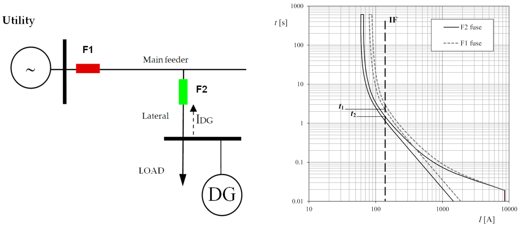
A classic coordination between protective fuses for non-DG rural electrical networks is shown in Figure 2. The sketch in the left side of this figure shows a radial network in which F1 is the fuse which protects the main line and F2 the one protecting the branch line. The criteria for a correct coordination between fuses state the following:
  • For faults in the main feeder, the F2 fuse will not detect any fault current, with F1 fuse being the one that will act as main protection.
  • For faults in the branch line, F2 will act as the main protection and F1 as a backup protection.
The graph included in Figure 2 shows the tripping characteristics of fuses F1 and F2. At the same fault current, IF, there should be a coordination margin such that the total operating time (upper boundary), t1, of the fuse acting as main protection, F2, should not exceed 75% of the minimum time, t2, in which the fuse acting as backup protection, F1, starts blowing (lower boundary) [33].
When the electrical network is working in a permanent regime, power balance is achieved. The generated power, PG, equals the power demanded by the loads, PL, plus a power loss, PP:
P G = P L + P P .
When DG is installed in the electrical network, the situation is different, as new power sources, PDG, are included:
P G + P D G = P L + P P .
As a consequence, the values of the currents in the permanent regime may change due to a new distribution of the loads’ current flow, causing the activation of the nearest fuse to the DG and compromising the coordination between this fuse and the one located immediately upstream.
Figure 3 shows a simple sketch of an electrical network with DG, and the corresponding curves of fuses F1 (backup protection) and F2 (main protection). In this situation, the power supplied by DG, PDG, might be larger than the one demanded by the load, PL. This situation is translated into the curves included in the graph from Figure 3: F2 fuse (closest to the DG) acts too close to the blowing starting point of fuse F1. If the power of the DG unit is increased, the coordination margin between the fuses would be altered and would cause both to trip untimely.

2.2. Modeling the Performance of Fuses

This article proposes a new method for the selection of protection fuses to avoid untimely tripping, and therefore achieving a more sustainable electrical network while maintaining the functionality of the protections. This procedure is based on a new mathematical modeling of the upper (ES) and lower (EI) boundary tripping curves of the fuses to be coordinated. For the upper boundary curve, two mathematical expressions are proposed, depending on the current, I, in relation to a specified value, I*:
1 t E S = i = 0 N 1 β i I i 2 ; I < I * i = 0 N 2 β i I i 2 ; I > I * .
For the lower boundary curve, one single equation is proposed:
1 t E I = i = 0 N β i I i 2 .
In the above equations, tES and tEI stand for the total operating time corresponding to the upper boundary curve of the fuse acting as the main protection, and the minimum melting time corresponding to the lower boundary curve of the fuse acting as backup protection, respectively. βi are characterization parameters of both the upper and the lower boundary curve of the fuse acting as backup protection.
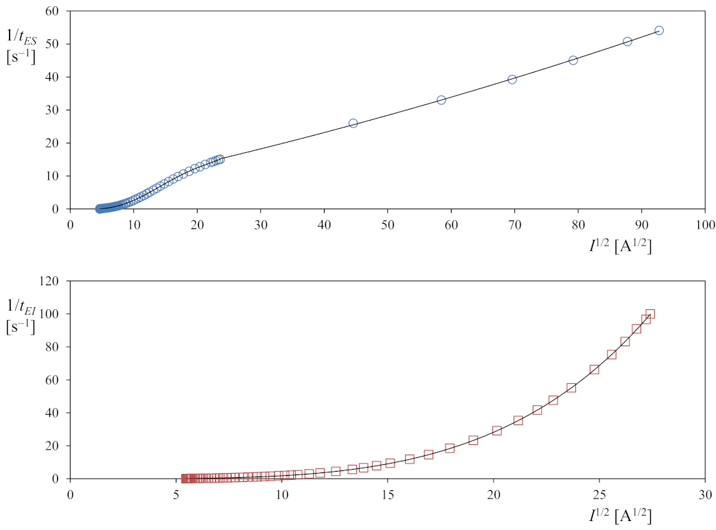
Equations (6) and (7), fitted to the upper curve of SMD-50 10E fuse and the lower curve of an SMD-50 15E fuse (both fuses manufactured by S&C Electric Company Chicago, IL, USA) are shown in Figure 4. In the first case, fifth- and second-order polynomials (N1 = 5 and N2 = 2) have been used, whereas in the second case, a fifth-order polynomial is used.
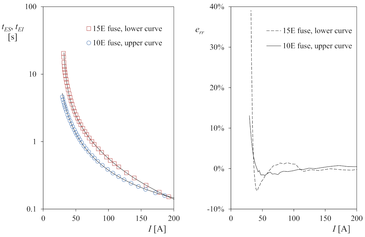
Additionally, it should be said that only the left branch of Equation (6) will be needed for the calculations. The translation of the above data to the normal time–current (t-I) graphs is included in Figure 5, in which the relative performance of fuses SMD-50 10E and SMD-50 15E can be compared (tES and tEI, respectively), together with the respective errors of the model, err. In Figure 5, it can be appreciated how this model fits the manufacturer’s data accurately, with less than 2% error within the normal current interval in which the fuses’ performance is analyzed.
For a proper protection coordination there must be a trip delay between two adjacent fuses that overcome the same electrical fault. The coordination criterion for protection fuses can be expressed as:
t E I = K t E S + C T I ,
where CTI is the coordination time interval (200–300 ms) [34,35] and K is a proportionality constant.

2.3. Distrtibution Network

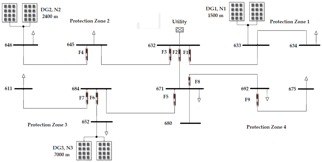
In the present work, the IEEE 13-bus test feeder system has been used to analyze the effect of the DG on the protection devices of the distribution network (see Figure 6). The distribution network has been divided into four protection zones:
  • Zone 1, connected to the substation through fuse F1
  • Zone 2, connected to the substation through fuse F3
  • Zone 3, connected to the substation through fuses F2 and F5
  • Zone 4, connected to the substation through fuses F2 and F8
Protection fuses F1, F2, F3 protect the aerial outputs of the main feeders (substation outputs). F4 protects the bus 646 where a DG unit has been installed. F5 and F6 protect the section 671-611, where DG has also been installed, and finally F8 and F9 protect the loads of protection zone 4 where no DG installation exists.
The case studies have been designed for three different locations of the DG in the network (bus/nodes 633, 646, and 652) and different levels of DG power penetration, specifically 25%, 50%, 75%, and 100%. The different case studies have been simulated with DIgSILENT© software from Power Factory [15], as this power system simulation software has a specific library for electrical protection. The locations of the DG in the distribution network are included in Table 1, the distance to the substation being also included in each case.
A nominal voltage of 20 kV is considered for the analyzed cases, the aerial cable being 47-AL1/8ST1A aluminum steel reinforced (see in Table 2 the main characteristics, according to EN 50182 standard [36]). The total load considered is 3.83 MW, which consists of several three-phase loads distributed according to the information included in Table 3.
When choosing the size of the expulsion fuses, the standards of the supplier [37] and the recommendations indicated by the IEC 60787 standard [38] have been taken into account. In addition, two supplementary criteria were established:
  • the nominal fuse current needs to be above the maximum expected generator load current with a sufficient margin (125% load)
  • the fuse should not trip with generator connection currents [34]
Each section of the distribution network in which the DG was installed was protected by expulsion fuses chosen to withstand up to 125% of the load current, in order to take into account the possible overloads that could appear in the network. Therefore, the following rules were set regarding the currents:
  • IF1 ≥ 1.25 ILOAD 634
  • IF2 ≥ 1.25 (ILOAD 611 + ILOAD 652 + ILOAD 692 + ILOAD 625 + ILOAD 671) > IF5
  • IF3 ≥ 1.25 (ILOAD 645 + ILOAD 646) > IF4
  • IF4 ≥ 1.25 ILOAD 646
  • IF5 ≥ 1.25 (ILOAD 611 + ILOAD 652) > IF6
  • IF6 ≥ 1.25 ILOAD 652
  • IF7 ≥ 1.25 ILOAD 611
  • IF8 ≥ 1.25 (ILOAD 692 + ILOAD 675) > IF9
  • IF9 ≥ 1.25 ILOAD 675
S&C Electric Company SMD-50 fuses were selected in this work to analyze the coordination. Table 4 includes the nominal currents of these fuses and their technical ID. Additionally, the constants of the model proposed in the present work (Equations (6) and (7)) fitted to the selected fuses are included in Table 5.

3. Cases Studied and Results

Two different groups of cases were analyzed. In the first one, the buses where the DG was installed are considered as PV bus nodes, whereas in the second one, PQ buses are considered. In Table 6 and Table 7, the results of the simulations carried out are included. The different cases of DG penetration and distribution (between bus nodes 633, 646, and 652) are indicated in Table 6 and Table 7. The information included states either:
  • correct performance, that is, no fuse is tripped, indicated by “OK”, or
  • possible incorrect performance, in which some fuses are tripped.
The cases of the first group (DG installed in PV bus) in which two consecutive fuses were tripped are analyzed in Table 8. In this table, the correct coordination between fuses is evaluated. The coordination time interval (Equation (8)) is derived from the tripping time of the fuses taking into account a proportionality constant K = 1. In all cases, CTI is larger than 0.3 s, with the exception of case 23 (100% DG penetration, distributed among bus 646, 75% penetration, and node 652, 25% penetration). In this case CTI = 0.088 s < 0.3 s, therefore a lack of coordination between fuses is observed. The cases corresponding to the second group (DG installed in PQ nodes) in which two consecutive fuses are tripped, are analyzed in Table 9. Among these cases, case 24 (100% DG penetration, distributed at node 646) resulted as Not OK (as CTI = 0.07, lower than the limit value). Finally, it should be emphasized that taking into account the whole set of simulations, DG considered as PV nodes had a larger amount of cases (59%) in which at least one fuse was tripped, whereas DG considered as PQ obtained a lower value of fuse-tripping cases (41%). This is caused by a larger current supply from the DG in the case of PV nodes.
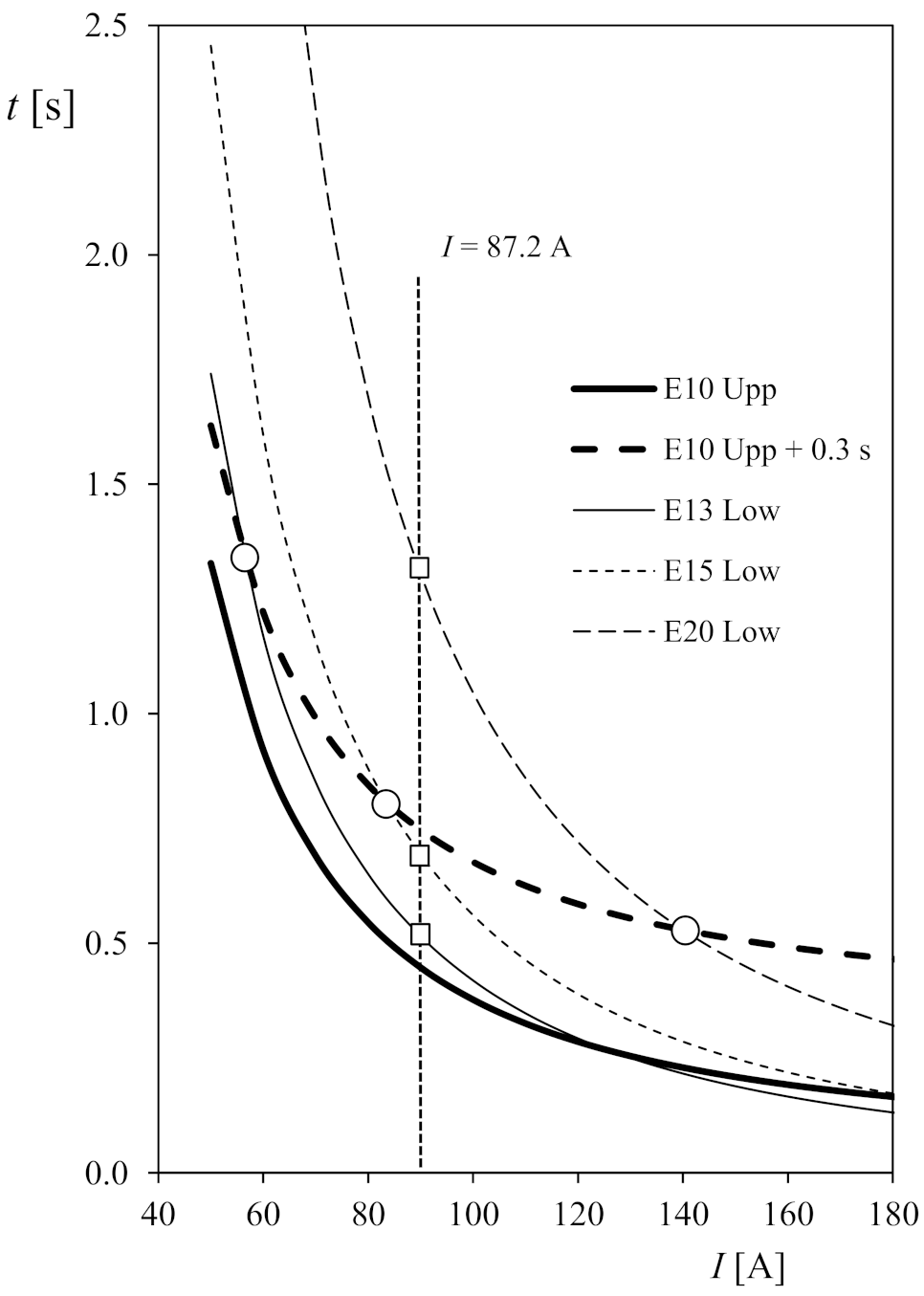
In case 23 of the IEEE 13-bus feeder system simulation considering DG installed in PV bus, fuses F3 and F4 tripped for I = 87.2 A current with a lack of coordination (that is, the time distance corresponding to the upper boundary curve of fuse F4, tES, and the lower boundary curve of fuse F3, tEI, is smaller than the coordination time interval, CTI = 0.3 s), that should be avoided by replacing one of the fuses. In Figure 7, the upper curve of fuse F4 (SMD-50 E10) and the lower curve of fuse F3 (SMD-50 E13) are plotted. It can be observed that the current intersects the fuse F3 curve at a point (indicated by an open square) located below the curve corresponding to fuse F4 plus a CTI = 0.3 s (which imply a lack of coordination). If fuse F3 is replaced by the next one in the family, characterized by a larger nominal current (SMD-50 E15), the situation is not solved, as at I = 87.2 A current the lower curve of the fuse has a tripping time lower than the one stated by the upper curve from fuse F4 plus a CTI = 0.3 s (also indicated by an open square in Figure 7). The problem is finally solved by selecting an SMD-50 E20 for the F3 fuse. See in Figure 7 how the tripping time of its lower curve at I = 87.2 A (indicated by an open square) detaches more than 0.3 s in relation to the SMD-50 E10 upper curve.
Besides, it is possible to work alternatively with the points of intersection between the lower curves of the selected fuses and the upper curve of fuse F4 (SMD-50 E10) plus a CTI = 0.3 s (open circles in Figure 7). From Equations (6)–(8), it is possible to derive the following equation:
1 i = 0 N β i I i 2 l o w e r = 1 i = 0 N β i I i 2 u p p e r + 0.3 ,
that includes two families of polynomials, the one corresponding to the upper curve of fuse F4, and the one corresponding to the lower value of the considered fuse for F3. From the above equation, it is possible to derive the value of the current which implies a correct coordination between fuses. The following current values were calculated with the data from Table 5: I = 56 A, I = 83.54 A, and I = 140 A, for the corresponding SMD-50 E13, SMD-50 E15, and SMD-50 E20 fuses (these values are the ones indicated in Figure 7 with open circles). As the first two values of the current are below the tripping current I = 87.2 A, there is a lack of coordination. In the latter case, the calculated value is larger than the tripping current. Therefore, for this current, the lower curve of SMD-50 E20 will be detached from the SMD-50 E10 upper curve a larger value than the one stated by the CTI (=0.3 s).
Going one step further, the fuse selected for F3 initially might be preserved and fuse F4 replaced by another one with smaller nominal current (if it is possible, bearing in mind the required nominal currents). The situation is very similar to the one described above; see Figure 8. In this case, fuses SMD-50 E10 and SMD-50 E7 cannot produce a proper coordination, the values of their upper curves at I = 87.2 A being detached from the SMD-50 E13 lower curve less than the CTI (points indicated with open squares). Nevertheless, fuse SMD-50 E5 selected as F4 fuse produces a proper coordination. Additionally, if Equations (6)–(8) are considered:
1 i = 0 N β i I i 2 l o w e r 0.3 = 1 i = 0 N β i I i 2 u p p e r ,
where the polynomial corresponding to the lower curve of fuse F3 (fuse SMD-50 E13, in this case) is constant, the polynomial corresponding to the upper curve being selected from the studied fuse at F4 in order to calculate the current that produces a proper coordination with fuse F3. These current values, I = 56 A (fuse SMD-50 E10), I = 79.1 A (fuse SMD-50 E7), and I = 93.5 A (fuse SMD-50 E5), are indicated in Figure 8 with open circles. From these values, it is possible to state that only selecting fuse SMD-50 E5 for fuse F4 will ensure a proper coordination. It should be underlined that the selection of fuses is also conditioned by their nominal current values.
The analysis corresponding to the other case with improper coordination detected between fuses (case 24 of simulations carried out considering DG installed in PQ nodes) is very similar to the one analyzed. In this case, the current at the line protected by fuses F3 and F4 is I = 93.2 A, which is very close to the mentioned current that indicates a proper coordination between fuse SMD-50 E5 at F4 and fuse SMD-50 E13 at F3. Nevertheless, the result is still valid.

4. Conclusions

The aim of this work is to analyze the fuse coordination in rural (or not too large) power networks with presence of photovoltaic DG. The performance of the fuses in the IEEE 13-bus feeder system with DG was studied with DIgSILENT©, and considering different power penetration levels and power distribution between the three bus nodes where the DG sources are installed (at close, moderate, and large distance from the substation). Besides, two options were considered in relation to these bus nodes, PV and PQ nodes, in order to study the widest scope of possibilities. The most relevant results of this work are:
  • The effect of photovoltaic DG on fuse coordination in a power network similar to the ones present in small rural villages has been checked. The results indicate that an improper coordination of fuses (correctly selected in the case of no DG presence) might be produced.
  • A new and easy way to simulate the performance of fuses has been described.
  • Thanks to the aforementioned new fuse modeling, criteria to select new fuses in power networks that can ensure a proper coordination between them have been described.
  • The present study can be extrapolated to networks with DG consisting of other kinds of sources (different from the photovoltaic ones), as the main control parameter is the current supplied to the network.

Author Contributions

Conceptualization, D.A.-G. and S.P.; methodology, D.A.-G., E.M.G.d.T., M.I.M.-L. and S.P.; software, D.A.-G.; validation, D.A.-G., D.A.-C., E.M.G.d.T. and M.I.M.-L.; formal analysis, D.A.-G.; investigation, D.A.-G., D.A.-C., E.M.G.d.T., M.I.M.-L. and S.P.; data curation, D.A.-G.; writing—original draft preparation, D.A.-C., D.A.-G. and S.P.; writing—review and editing, D.A.-C., D.A.-G. and S.P.; supervision, D.A.-G. and S.P. All authors have read and agreed to the published version of the manuscript.

Funding

This research received no external funding.

Institutional Review Board Statement

Not applicable.

Informed Consent Statement

Not applicable.

Acknowledgments

The authors are indebted to the head of the IDR/UPM Institute, Ángel Sanz-Andrés, for his support.

Conflicts of Interest

The authors declare no conflict of interest.

References

  1. Paithankar, Y.G.; Bhide, S.R. Fundamentals of Power System Protection; PHI Learning Pvt. Ltd.: Delhi, India, 2010. [Google Scholar]
  2. Barrenetxea, A.I. Protecciones de Sistemas de Potencia; Universidad del País Vasco, Servicio Editoria/Euskal Herriko Unibertsitatea, Argitalpen Zerbitzua: Biscay, Spain, 1997. [Google Scholar]
  3. Dugan, R.C.; McDermott, T.E. Operating conflicts for distributed generation on distribution systems. In Proceedings of the Papers—Rural Electric Power Conference, Little Rock, AR, USA, 29 April–1 May 2001. [Google Scholar]
  4. Salman, S.K.; Rida, I.M. Investigating the impact of embedded generation on relay settings of utilities’ electrical feeders. IEEE Trans. Power Deliv. 2001, 16, 246–251. [Google Scholar] [CrossRef]
  5. Bastião, F.; Cruz, P.; Fiteiro, R. Impact of distributed generation on distribution networks. In Proceedings of the 2008 5th International Conference on the European Electricity Market, EEM, Lisboa, Portugal, 28–30 May 2008. [Google Scholar]
  6. Barker, P.P.; De Mello, R.W. Determining the impact of distributed generation on power systems: Part 1—Radial distribution systems. In Proceedings of the IEEE Power Engineering Society Transmission and Distribution Conference, Seattle, WA, USA, 16–20 July 2000; Volume 3, pp. 1645–1656. [Google Scholar]
  7. Dadkhah, M.; Fani, B.; Heydarian-Forushani, E.; Mohtaj, M. An off-line algorithm for fuse-recloser coordination in distribution networks with photovoltaic resources. Int. Trans. Electr. Energy Syst. 2020, 30, 1–16. [Google Scholar] [CrossRef]
  8. Deng, W.; Pei, W.; Qi, Z. Impact and improvement of distributed generation on voltage quality in micro-grid. In Proceedings of the 3rd International Conference on Deregulation and Restructuring and Power Technologies, DRPT 2008, Nanjing, China, 6–9 April 2008; pp. 1737–1741. [Google Scholar]
  9. Wang, S. Distributed generation and its effect on distribution network system. In Proceedings of the IET Conference Publications, Prague, Czech Republic, 8–11 June 2009. [Google Scholar]
  10. Naiem, A.F.; Hegazy, Y.; Abdelaziz, A.Y.; Elsharkawy, M.A. A classification technique for recloser-fuse coordination in distribution systems with distributed generation. IEEE Trans. Power Deliv. 2012, 27, 176–185. [Google Scholar] [CrossRef]
  11. Hadjsaid, N.; Canard, J.; Dumas, F. Dispersed generation impact on distribution networks. IEEE Comput. Appl. Power 1999, 12, 22–28. [Google Scholar] [CrossRef]
  12. Girgis, A.; Brahma, S. Effect of distributed generation on protective device coordination in distribution system. In Proceedings of the LESCOPE 2001—2001 Large Engineering Systems Conference on Power Engineering: Powering Beyond 2001, Halifax, NS, Canada, 11–13 July 2001; pp. 115–119. [Google Scholar]
  13. Brahma, S.M.; Girgis, A.A. Development of Adaptive Protection Scheme for Distribution Systems with High Penetration of Distributed Generation. IEEE Trans. Power Deliv. 2004, 19, 56–63. [Google Scholar] [CrossRef]
  14. Chaitusaney, S.; Yokoyama, A. Prevention of reliability degradation from recloser-fuse miscoordination due to distributed generation. IEEE Trans. Power Deliv. 2008, 23, 2545–2554. [Google Scholar] [CrossRef]
  15. Boonyapakdee, N.; Konghirun, M.; Sangswang, A. Separated phase-current controls using inverter-based DGs to mitigate effects of fault current contribution from synchronous DGs on recloser-fuse. Appl. Sci. 2019, 9, 4311. [Google Scholar] [CrossRef] [Green Version]
  16. Razavi, S.E.; Rahimi, E.; Javadi, M.S.; Nezhad, A.E.; Lotfi, M.; Shafie-khah, M.; Catalão, J.P.S. Impact of distributed generation on protection and voltage regulation of distribution systems: A review. Renew. Sustain. Energy Rev. 2019, 105, 157–167. [Google Scholar] [CrossRef]
  17. Bayati, N.; Baghaee, H.R.; Hajizadeh, A.; Soltani, M. A Fuse Saving Scheme for DC Microgrids with High Penetration of Renewable Energy Resources. IEEE Access 2020, 8, 137407–137417. [Google Scholar] [CrossRef]
  18. Alam, M.N.; Das, B.; Pant, V. Protection scheme for reconfigurable radial distribution networks in presence of distributed generation. Electr. Power Syst. Res. 2020, 106973. [Google Scholar] [CrossRef]
  19. Santoso, S.; Short, T.A. Identification of fuse and recloser operations in a radial distribution system. IEEE Trans. Power Deliv. 2007, 22, 2370–2377. [Google Scholar] [CrossRef]
  20. Yazdanpanahi, H.; Li, Y.W.; Xu, W. A new control strategy to mitigate the impact of inverter-based DGs on protection system. IEEE Trans. Smart Grid 2012, 3, 1427–1436. [Google Scholar] [CrossRef]
  21. Hussain, B.; Sharkh, S.M.; Hussain, S.; Abusara, M.A. An adaptive relaying scheme for fuse saving in distribution networks with distributed generation. IEEE Trans. Power Deliv. 2013, 28, 669–677. [Google Scholar] [CrossRef]
  22. Nojavan, M.; Seyedi, H.; Mahari, A.; Zare, K. Optimization of Fuse-Recloser Coordination and Dispersed Generation Capacity in Distribution Systems. Majlesi J. Electr. Eng. 2014, 8, 15–24. [Google Scholar]
  23. Yousaf, M.; Mahmood, T. Protection coordination for a distribution system in the presence of distributed generation. Turkish J. Electr. Eng. Comput. Sci. 2017, 25, 408–421. [Google Scholar] [CrossRef]
  24. Plesca, A. Temperature distribution of HBC fuses with asymmetric electric current ratios through fuselinks. Energies 2018, 11, 1990. [Google Scholar] [CrossRef] [Green Version]
  25. Chaitusaney, S.; Yokoyama, A. Reliability analysis of distribution system with distributed generation considering loss of protection coordination. In Proceedings of the 2006 9th International Conference on Probabilistic Methods Applied to Power Systems, PMAPS, Stockholm, Sweden, 11–15 June 2006. [Google Scholar]
  26. Braga, G.; Zanin Bertoletti, A.; Peres de Morais, A.; Ghendy Cardoso, J. Curve Fitting Analysis of Expulsion Fuse Links through the Cross-Validation Technique. In Proceedings of the 2018 IEEE PES Transmission & Distribution Conference and Exhibition—Latin America (T&D-LA), Lima, Peru, 18–21 September 2018; pp. 1–5. [Google Scholar]
  27. Fazanehrafat, A.; Javadian, S.A.M.; Bathaee, S.M.T.; Haghifam, M.R. Maintaining the recloser-fuse coordination in distribution systems in presence of DG by determining DG’s size. In Proceedings of the IET 9th International Conference on Developments in Power Systems Protection (DPSP 2008), Glasgow, UK, 17–20 March 2008; pp. 132–137. [Google Scholar]
  28. Tang, Y.; Ayyanar, R. Verification of Protective Device Coordination in Distribution Systems with Photovoltaic Generation. In Proceedings of the 2014 IEEE 40th Photovoltaic Specialist Conference (PVSC), Denver, CO, USA, 8–13 June 2014; pp. 2100–2105. [Google Scholar] [CrossRef]
  29. Abdel-ghany, H.A.; Azmy, A.M.; Elkalashy, N.I.; Rashad, E.M. Optimizing DG penetration in distribution networks concerning protection schemes and technical impact. Electr. Power Syst. Res. 2015, 128, 113–122. [Google Scholar] [CrossRef]
  30. Conde Enríquez, A.; Vázquez-Martínez, E. Enhanced time overcurrent coordination. Electr. Power Energy Syst. 2006, 76, 457–465. [Google Scholar] [CrossRef]
  31. Conde Enríquez, A.; Vázquez-Martínez, E.; Altuve-Ferrer, H.J. Time overcurrent adaptive relay. Electr. Power Energy Syst. 2003, 25, 841–847. [Google Scholar] [CrossRef]
  32. Costa, G.B.; Marchesan, A.C.; Morais, A.P.; Cardoso, G.; Gallas, M. Curve Fitting Analysis of Time-Current Characteristic of Expulsion Fuse Links. In Proceedings of the 2017 IEEE International Conference on Environment and Electrical Engineering and 2017 IEEE Industrial and Commercial Power Systems Europe (EEEIC/I&CPS Europe), Milan, Italy, 6–9 June 2017; pp. 1–6. [Google Scholar]
  33. Gers, J.M.; Holmes, E.H. Protection of Distribution Networks; The Institution of Electrical Engineers: London, UK, 2004. [Google Scholar]
  34. Anderson, P. Power System Protection; Wiley: Hoboken, NJ, USA, 1998. [Google Scholar]
  35. Viawan, F.A.; Karlsson, D.; Sannino, A.; Daalder, J. Protection scheme for meshed distribution systems with high penetration of distributed generation. In Proceedings of the 2006 Power Systems Conference: Advanced Metering, Protection, Control, Communication, and Distributed Resources, Clemson, SC, USA, 14–17 March 2006; pp. 99–104. [Google Scholar]
  36. UNE-EN 50182:2002/AC:2013: Conductores para Líneas Eléctricas Aéreas. Conductores de Alambres Redondos Cableados en Capas Concéntricas. Available online: https://www.une.org/encuentra-tu-norma/busca-tu-norma/norma/?c=N0051959 (accessed on 24 March 2021).
  37. Iberdrola MT 2.13.40: Criterios de Selección y Adaptación del Calibre de los Fusibles de MT para Centros de Transformación. 2003. Available online: https://docplayer.es/40982302-Procedimiento-de-seleccion-y-adaptacion-del-calibre-de-los-fusibles-de-mt-para-centros-de-transformacion.html (accessed on 24 March 2021).
  38. IEC 60783. Application Guide for the Selection of Fuse-Links of High-Voltage Fuses for Transformer Circuit Applications. 1983. Available online: https://standards.globalspec.com/std/113389/IEC%2060787 (accessed on 24 March 2021).
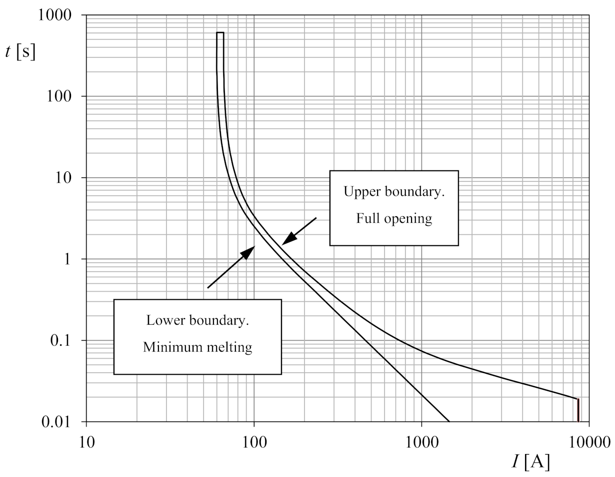
Figure 1. Tripping characteristic curve of an expulsion fuse.
Agronomy 11 00622 g001
Figure 2. Classic coordination between protective fuses in non-DG radial distribution networks. (Left) Sketch of a radial distribution network without the presence of a DG. (Right) Operating characteristics curves of protection fuses F1 and F2.
Agronomy 11 00622 g002
Figure 3. Loss of coordination between fuses in the distribution network with the presence of DG. (Left) Sketch of a radial distribution network with DG. (Right) Operating characteristics curves of protection fuses F1 and F2.
Agronomy 11 00622 g003
Figure 4. Upper and lower curves that define fuse behavior (Equations (6) and (7)). (Top) Inverse of the total operation time, tES, in relation to the root of the current for the SMD-50 10E fuse. Equation (6) has been fitted to the manufacturer’s data (I < 558 A; N1 = 5; β0 = −1.19851, β1 = 7.03361 × 10⁻¹, β2 = −1.91430 × 10⁻¹, β3 = 2.59919 × 10⁻², β4 = −1.18321 × 10⁻³, β5 = 1.79907 × 10⁻⁵; I > 558 A; N2 = 2; β0 = 5.09321, β1 = 3.95777 × 10⁻¹, β2 = 1.40653 × 10⁻³). (Bottom) Inverse of the minimum melting time, tEI, in relation to the root of the current for the SMD-50 15E fuse. Equation (7) has been fitted to the manufacturer’s data (N = 5; β0 = 2.93095, β1 = 1.17318, β2 = −1.84165 × 10⁻¹, β3 = 1.40294 × 10⁻², β4 = −3.33170 × 10⁻⁴, β5 = 6.99420 × 10⁻⁶).
Agronomy 11 00622 g004
Figure 5. (Left) SMD-50 10E fuse upper curve and SMD-50 15E fuse lower curve from the manufacturer’s data. Equations (6) and (7) have been fitted to these data (solid lines). (Right) Error, err, of the proposed fuse model with regard to the manufacturer’s data.
Agronomy 11 00622 g005
Figure 6. IEEE 13-bus test feeder system used to analyze the performance of the fuses in relation to the DG.
Agronomy 11 00622 g006
Figure 7. Selection of fuses to avoid the uncorrected coordination detected in case 23 of the calculations considering PV nodes where the photovoltaic DG are installed. The upper tripping time curve, tES, of SMD-50 E10 fuse selected for F4 fuse location (see Figure 6) is plotted, together with the lower tripping time curves, tEI, corresponding to SMD-50 E13, SMD-50 E15, and SMD-50 E20 fuses. The points of these curves corresponding to current I = 87.2 A obtained from the simulation of case 23 are indicated (open squares). The points corresponding to a proper coordination between fuse SMD-50 E10 as F4 with SMD-50 E13, SMD-50 E15, and SMD-50 E20 fuses as F3 are also indicated (open circles).
Agronomy 11 00622 g007
Figure 8. Selection of fuses to avoid the uncorrected coordination detected in case 23 of the calculations considering PV nodes where the photovoltaic DG are installed. The lower tripping time curve, tEI, of SMD-50 E13 fuse selected for F3 fuse location (see Figure 6) is plotted, together with the upper tripping time curves, tES, corresponding to SMD-50 E10, SMD-50 E7, and SMD-50 E5 fuses. The points of these curves corresponding to current I = 87.2 A obtained from the simulation of case 23 are indicated (open squares). The points corresponding to a proper coordination between fuse SMD-50 E13 as F3 with SMD-50 E10, SMD-50 E7, and SMD-50 E5 fuses as F4 are also indicated (open circles).
Agronomy 11 00622 g008
Table 1. Location (node) and distance of the DG from the substation (SE).
NodeDistance (m)Description
Node 633 (N1)1500 Close to SE
Node 646 (N2)2400Moderate distance to SE
Node 652 (N3)7000 Far from SE
Table 2. Characteristics of 47-AL1/8ST1A aluminum steel reinforced cable [36].
Electrical resistance at 20 °C [Ω·km−1]0.614
Electrical reactance at 20 °C [Ω·km−1]0.41
Max. constant current [kA]0.202
Table 3. Loads considered in the analyzed network.
LocationTypePower [MW]
Node 634Type Y1.5
Node 611Type Y0.056
Node 645Type Y0.056
Node 646Type D0.5
Node 652Type Y1
Node 671Type D0.385
Node 675Type Y0.281
Node 692Type D0.056
Table 4. Nominal currents of the fuses installed in the distribution network.
FuseI [A]Fuse Selected
F153.75S&C SMD-50 30E
F262.5S&C SMD-50 40E
F320S&C SMD-50 13E
F417.5S&C SMD-50 10E
F5IF2 > 37.5 ≥ IF6+ IF7S&C SMD-50 30E
F635S&C SMD-50 20E
F72.5S&C SMD-50 5E
F8IF2 > 12.5≥ IF9S&C SMD-50 10E
F910S&C SMD-50 7E
Table 5. Coefficients of Equations (6) and (7) fitted to the upper (upp) and lower (low) tripping time curves, tES and tEI, of different S&C Electric Company SMD-50 fuses. See also Figure 4 and Figure 5.
FuseCurveβ0
[s−1]
β1
[s−1·A0.5]
β2
[s−1·A1]
β3
[s−1·A1.5]
β4
[s−1·A2]
β5
[s−1·A2.5]
5Eupp; I < 299 A−1.874601.3974−4.58631 × 10−17.76704 × 10−2−4.78102 × 10−39.97543 × 10−5
upp; I > 299 A6.838073.61221 × 10−11.58040 × 10⁻³---
low−3.695552.55339−6.63554 × 10−18.13467 × 10−2−3.23895 × 10−31.03372 × 10−4
7Eupp; I < 430 A−1.511119.79975 × 10−1−2.84227 × 10−14.17970 × 10−2−2.15210 × 10−33.72960 × 10−5
upp; I > 430 A5.823413.86086 × 10−11.42370 × 10⁻³---
low−8.63283 × 10−13.42341 × 10−1−4.85652 × 10−23.13876 × 10−36.24309 × 10−49.06465 × 10−7
10Eupp; I < 558 A−1.198517.03361 × 10−1−1.91430 × 10−12.59919 × 10−2−1.18321 × 10−31.79907 × 10−5
upp; I > 558 A5.093213.95777 × 10−11.40653 × 10⁻³---
low−2.25987 × 10⁻¹−7.04764 × 10−23.90330 × 10−2−5.07612 × 10−36.52842 × 10−4−4.82039 × 10⁻⁶
13Eupp; I < 722 A−1.788248.59426 × 10−1−1.82664 × 10−11.98489 × 10−2−7.64613 × 10−49.99949 × 10−6
upp; I > 722 A3.780764.24034 × 10−11.25333 × 10⁻³---
low−5.38095 × 10−15.39468 × 10−21.66285 × 10⁻²−2.91772 × 10−33.92933 × 10−4−2.89251 × 10⁻⁶
15Eupp; I < 826 A−1.903898.37374 × 10−1−1.64212 × 10−11.64897 × 10−2−5.90620 × 10−47.21544 × 10−6
upp; I > 826 A3.780764.24034 × 10−11.25333 × 10⁻³---
low−2.930951.17318−1.84165 × 10−11.40294 × 10−2−3.33170 × 10−46.99420 × 10−6
20Eupp; I < 1138−1.691136.44722 × 10−1−1.09999 × 10−19.57500 × 10−3−2.88718 × 10−42.96029 × 10−6
upp; I > 11386.64811 × 10−14.79303 × 10−19.81018 × 10−4---
low−1.551314.65904 × 10−1−5.60123 × 10−23.39124 × 10−3−4.81103 × 10−61.06292 × 10−6
25Eupp; I < 1458−2.401367.94736 × 10−1−1.10811 × 10−17.81405 × 10−3−2.01186 × 10−41.79140 × 10−6
upp; I > 1458−1.974545.25978 × 10−17.36144 × 10⁻⁴---
low−2.868868.54336 × 10−01−9.67943 × 10−25.21690 × 10−3−7.42881 × 10−51.23231 × 10−6
30Eupp; I < 1608 A−2.180196.71422 × 10−1−9.07023 × 10−26.20992 × 10−3−1.51163 × 10−41.26547 × 10−6
upp; I > 1608 A−2.644645.27075 × 10−17.90099 × 10⁻⁴---
low−1.275312.68551 × 10−1−2.21904 × 10−29.05809 × 10−42.87958 × 10−51.36786 × 10−7
40Eupp; I < 2065 A−1.565024.32637 × 10−1−5.62540 × 10−23.66028 × 10−3−7.87726 × 10−55.76520 × 10−7
upp; I > 2065 A−6.659365.92598 × 10−14.68242 × 10⁻⁴---
low−1.83832 × 10⁻²−1.07938 × 10−11.62356 × 10−2−8.70876 × 10−44.91068 × 10−5−1.84714 × 10⁻⁷
50Eupp; I < 2517 A−2.638576.27277 × 10−1−6.44707 × 10−23.34754 × 10−3−6.24271 × 10−54.05220 × 10−7
upp; I > 2517 A−8.973516.01037 × 10−15.73675 × 10⁻⁴---
low−2.283084.41665 × 10−1−3.36337 × 10−21.24261 × 10−3−2.86096 × 10−61.46350 × 10−7
65Eupp; I < 3397 A−2.022024.32137 × 10−1−4.03342 × 10−21.85871 × 10−3−2.89685 × 10−51.55962 × 10−7
upp; I > 3397 A−1.68545 × 10+17.07076 × 10−11.20284 × 10−4---
low−6.28233 × 10−15.43519 × 10−2−1.10800 × 10⁻³−3.06980 × 10−51.19222 × 10−5−1.96977 × 10⁻⁸
Table 6. IEEE 13-bus feeder system (Figure 6), simulated considering PV nodes. The status result (either “OK” when no fuse was tripped, or including the unexpected tripped fuses) of the different cases related to DG power penetration level and its distribution among the 3 DG installed (bus nodes 633, 646, and 652) are included in the table.
DGCaseDG DistributionStatus Result
Bus 633Bus 646Bus 652
25%1--25%OK
2-25%-OK
325%--OK
50%4--50%OK
5-25%25%F3, F4
6-50%-F3, F4
725%-25%OK
825%25%-F4
950%--OK
75%10--75%F6
11-25%50%OK
12-50%25%F3, F4, F6
13-75%-F3, F4
1425%-50%OK
1525%25%25%F3, F4
1625%50%-F3, F4
1750%-25%OK
1850%25%-OK
1975%--OK
100%20--100%F5, F6
21-25%75%F5, F6
22-50%50%F4
23-75%25%F3, F4, F6
24-100%-F4
2525%-75%F6
2625%25%50%F4
2725%50%25%F4
2825%75%-F4
2950%-50%OK
3050%25%25%F4
3150%50%-F4
3275%-25%OK
3375%25%-OK
34100%--F1
Table 7. IEEE 13-bus feeder system (Figure 6), simulated considering PQ nodes. The status result (either “OK” when no fuse was tripped, or including the unexpected tripped fuses) of the different cases related to DG power penetration level and its distribution among the 3 DG installed (bus nodes 633, 646, and 652) are included in the table.
DGCaseDG DistributionResult
Bus 633Bus 646Bus 652
25%1--25%OK
2-25%-OK
325%--OK
50%4--50%OK
5-25%25%OK (*)
6-50%-F3, F4
725%-25%OK
825%25%-OK (*)
950%--OK
75%10--75%F6
11-25%50%OK
12-50%25%F3, F4
13-75%-F3, F4
1425%-50%OK
1525%25%25%OK (*)
1625%50%-F3, F4
1750%-25%OK
1850%25%-OK
1975%--OK
100%20--100%F5, F6
21-25%75%F6
22-50%50%F4
23-75%25%F3, F4
24-100%-F3, F4
2525%-75%F6
2625%25%50%OK (*)
2725%50%25%F3, F4
2825%75%-OK
2950%-50%OK
3050%25%25%OK
3150%50%-F3, F4
3275%-25%OK
3375%25%-OK
34100%--F1
(*) Fuse is tripped if PV nodes are considered (see Table 6).
Table 8. IEEE 13-bus feeder system (Figure 6), simulated considering PV nodes. Fuse coordination results (tripping times) and compliance in cases where two consecutive fuses tripped (see Table 6).
CaseZone 1Zone 2Zone 3CTI [s]Status Result
tF1 [s]tF3 [s]tF4 [s]tF2 [s]tF5 [s]tF6 [s]CTI > 0.3 s
5-7.843.48---4.36OK
6-3.161.61---1.55OK
12-1.370.75--3.110.62OK
13-0.940.52---0.42OK
15-5.012.55---2.46OK
16-1.160.65 --0.51OK
20----4.161.432.73OK
21-5.452.73-29.582.842.72OK
23-0.560.47--6.160.09Not OK
Table 9. IEEE 13-bus feeder system (Figure 6), simulated considering PQ nodes. Fuse coordination results (tripping times) and compliance in cases where two consecutive fuses tripped (see Table 7).
CaseZone 1Zone 2Zone 3CTI [s]Status Result
tF1 [s]tF3 [s]tF4 [s]tF2 [s]tF5 [s]tF6 [s]CTI > 0.3 s
6-3.271.67---1.60OK
12-3.291.67---1.62OK
13-1.000.55---0.45OK
16-3.281.67---1.67OK
20- -6.241.784.46OK
23-1.000.55---0.45OK
24-0.490.42---0.07Not OK
27-3.301.68---1.62OK
28-1.000.55---0.45OK
31-3.291.68---1.61OK
Publisher’s Note: MDPI stays neutral with regard to jurisdictional claims in published maps and institutional affiliations.