In this section, the selected agricultural field for benchmark of metaheuristic algorithms was adopted to determine all the possible capacitated coverage solutions of the field and to find the absolute optimal solution, which is a coverage plan for the field with minimum non-working driving distance concerning the constraints of the capacitated field operation. The two metaheuristic algorithms, simulated annealing algorithm (SAA) and ant colony optimization (ACO), were examined and their near-optimal solutions were compared to the absolute solution for the candidate field. When selecting the benchmarking field, the complexity of the problem should be taken into account since the size of the solution space depends on the number of tracks in the field.
2.1. Terminology
Most field operations require that the field is covered exactly once; ideally, no part of the field should receive neither none nor multiple treatments. To achieve this, it is convenient to represent the field geometrically. This is done by selecting a driving direction and dividing the field area into parallel rows along the driving direction with a width equal to the working width of the machine used for the operation in question. The centerline of each row is called a track and by following the track of each row the field will be covered. In order to change from one track to another, an area for turning is defined at the end of the rows. This area is denoted the headland, and the remaining part of the field is denoted the field body. In some operations, notably harvesting, the headland is treated before the field body to make room for the turnings; however, in operations such as fertilization, the headland is normally treated after the field body. The width of the headland must be sufficient for the machine to turn, and additionally, it must be an integral multiple of the working width. This number is called the headland pass. The total distance driven to cover the field can be divided into the working distance and the non-working distance. The working distance is constant and can be calculated as the field area in square meters divided by the working width in meters. The non-working distance, which is the optimization criterion in this work, is the total unproductive distance, e.g., for changing tracks. For capacitated field operations, material is either removed from (harvest) or brought into (sowing, fertilization, etc.) the field. The material is collected from or delivered to a depot. The material is transported in a bin with a certain bin capacity. In this study, we require the bin capacity to be sufficient to cover the demand of any track. We also only consider a single depot for simplicity.
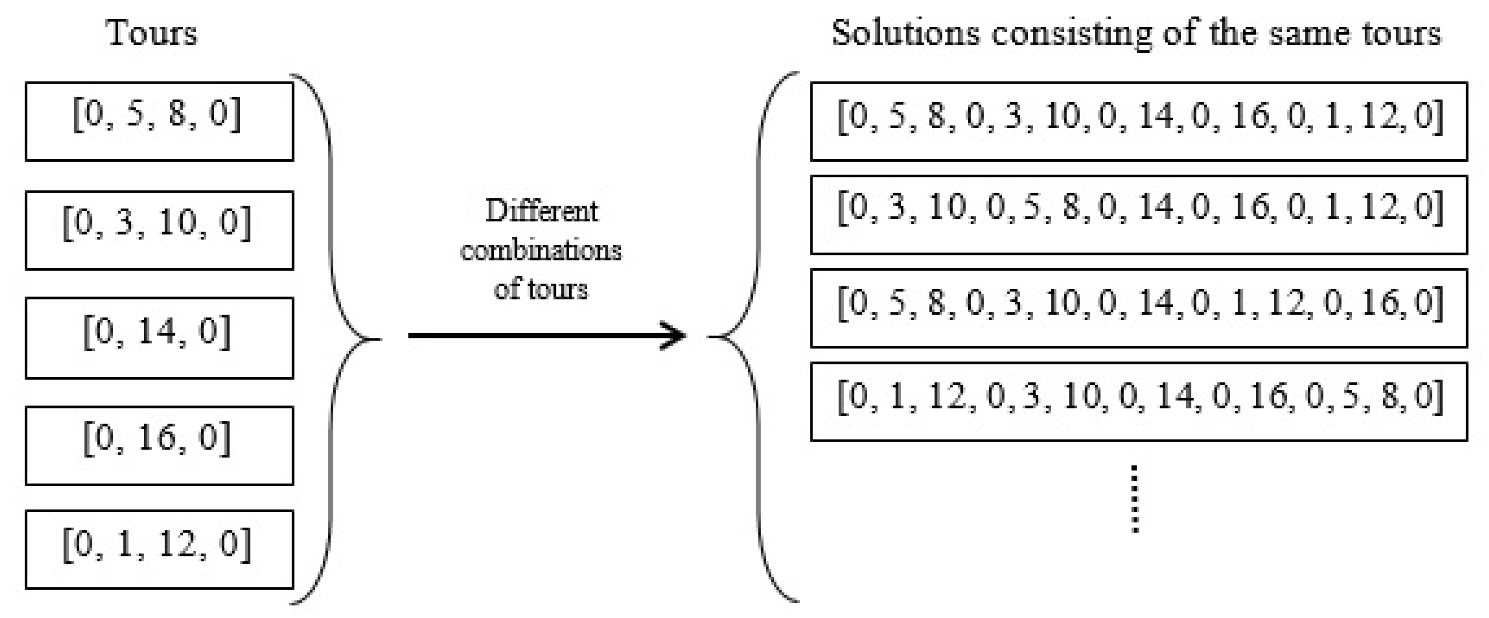
Any ordering of the tracks of a field with a direction of the tracks constitutes a route or a solution to the covering problem. The cost of a solution is the total non-working distance of the coverage. An optimal or an absolute solution is a solution with the lowest cost value. Since the cost value is dependent on both the order and the driving direction of the tracks, it can be listed by the sequence of endpoints of the tracks. If a field has N tracks, the endpoints of the ith track can be noted 2i − 1 and 2i, for i = 1, …, N. A track can be referred to either by its number, i, or by its endpoints, [2i − 1, 2i]. For a field with 8 tracks, a solution could be noted as a sequence of all 16 track endpoints, e.g., [0, 8, 7, 11, 12, 6, 5, 1, 2, 4, 3, 9, 10, 16, 15, 13, 14, 0], where 0 is a common starting and ending point of the route. In this solution, the first track to visit is number 4 in the direction from endpoint 8 to 7, then track 6 in the direction from endpoint 11 to 12, and so forth. The same solution can be written simpler by only listing the entry endpoints of the tracks: [0, 8, 11, 6, 1, 4, 9, 16, 13, 0] since the exit endpoint is given from the entry. For a capacitated operation, 0 indicates the ID of the depot and the solution includes 0’s when the machine must return to the depot to refill/unload, e.g., [0, 8, 11, 6, 1, 0, 4, 9, 16, 13, 0]. This solution contains a single refill/unload visit to the depot, so it consists of two tours, i.e., [0, 8, 11, 6, 1, 0] and [0, 4, 9, 16, 13, 0]. Two tours are considered equivalent if they consist of the same tracks, only in opposite direction. Moreover, two solutions are equivalent if they consist of the same or equivalent tours in different orderings.
2.2. Calculating the Number of Solutions
The size of the solution space has been calculated as a function of the number of tracks,
N.
Figure 1 illustrates the number of different ways to cover a field with
N = 8 tracks when an uncapacitated operation is considered, and each track must be visited exactly once. The 8 tracks can be permuted in 8
! ways and each track can be traversed in one of two directions
. This results in
= 10,321,920. different solutions which is demonstrated in the
Figure 1. In general, the number of solutions
PN for an uncapacitated operation in a field with
N tracks is expressed by (1):
Considering one of the
P8 possible solutions, say [0, 8, 11, 6, 1, 4, 9, 16, 13, 0], it can be changed into a solution for a capacitated operation by adding zeroes, corresponding to visits at the depot for unloading/refilling the bin. For example [0, 8, 11, 0, 6, 1, 4, 9, 0, 16, 13, 0] is a solution with two intermediate depot visits. The number of ways to add two zeroes between the eight-track endpoints is equal to the number of ways 2 items can be selected from 7, namely 21 which is shown in (2):
Thus, in general, the number of capacitated solutions corresponding to each uncapacitated is calculated as the number of ways to add 0, 1, 2,…,
N − 1 zeroes between the
N track endpoints. This is expressed in (3):
Finally, the total number of solutions to cover a field with
N tracks with a capacitated operation is shown in (4):
The total number of solutions for seven, eight, nine, and ten tracks are shown in
Table 1.
Figure 2 shows how the number of solutions,
TN, increases dramatically with the increasing number of tracks,
N. The logarithmic scale reveals that the solution size increases even faster than exponentially. Based on these calculations it was decided to select a benchmarking field with eight tracks to make it feasible to create and evaluate all possible solutions and determine the optimal solution for comparison by metaheuristic algorithms.
2.4. Calculating All Possible Solutions and Determining the Best
In order to calculate the non-working distance of all 1,321,205,760 solutions of the benchmarking field (
Figure 3) a geometrical representation of the field was made according to the method introduced by [
29]. Slurry fertilization was selected as a representative capacitated operation, and necessary input variables to specify the field, operation, machine, and implement were assigned values, as shown in
Table 3.
Based on the method presented in [
10,
26,
29] a geometrical representation of the field was produced, as shown in
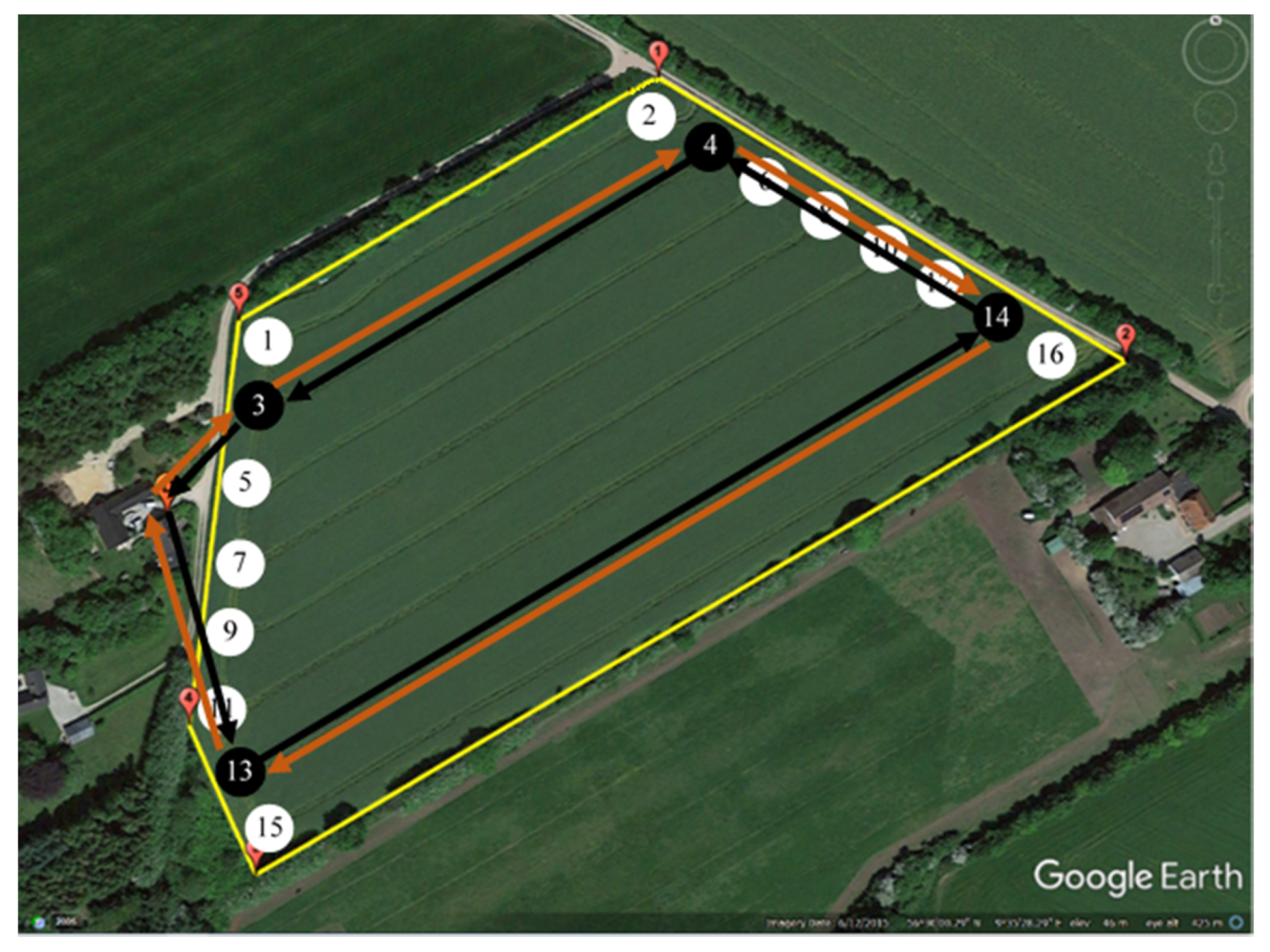
Figure 4. This included a representation of the field polygon, tracks with coordinates of their endpoints, turnings between tracks, coordinates of the depot, as well as the length and demand of each track. The demand for a track was calculated proportionally to its length, such that the fertilizer requirement was distributed evenly over the area.
The tracks were numbered and given endpoint IDs as shown in
Figure 5. The resulting track lengths and demands are shown in
Table 4.
It is important to note that not all
= 1,321,205,760 solutions are feasible. A solution is not feasible if it contains a tour where the sum of demands of the tracks of the tour, according to the track demands of
Table 4, exceeds the bin capacity displayed in
Table 3.
Graph modelling was applied to generate a field graph consist of all the types of edges (connections) in the field. There are six types of edges between each pair of the vertices and each defined edge has a length [
18]:
Gate to Headland (G2H): two edges connect the gate to the headland path
Headland (H): the connection between two subsequent vertices in headland path
Track (T): the connection between two pairs of nodes (two ends of a fieldwork area).
Track to Headland (T2H): the connection between track nodes and vertices in the headland
Track to track (T2T): the connection between the end nodes of two adjacent tracks
Headland to headland (H2H): the connection between two headland paths
These turns are generated based on the Dubin’s Curves method [
30]. In graph search, to find the shortest non-working distance between each pair of endpoints, Dijkstra’s method is applied [
31]. This resulted in the cost matrix (
Table A1 in
Appendix A) where the entry
is the non-working distance between endpoint
i and
j [
10]. For instance, the shortest path selected by Dijkstra algorithm to travel from Depot (0) to Node (1) is [1, 16, 17, 18, 38]. The edges types are [1 → 16: (G2H), 16 → 17: (H), 17 → 18: (H), 18 → 38: (T2H)]. Therefore, the shortest non-working distance between Depot (0) and Node (1) is the summation of the length related to those edges [38.0664, 3.1591, 4.0192, and 32.2888] which is equal to 77.5335. The cost matrix has a row and column for each track’s endpoint and the depot, so it is a square matrix of dimension
, where
is the number of tracks. The distance from each endpoint back to itself is zero, hence the diagonal of the cost matrix is zero (
). Likewise, the distance from endpoints
to
is the same as from
to
, so the cost matrix is symmetric (
).
2.6. The Simulated Annealing Algorithm
The Simulated Annealing Algorithm (SAA) [
17,
18] is one of the most popular metaheuristic methods for solving combinatorial optimization problems. It simulates the physical process called annealing, where the properties of a material, typically a metal or an alloy, are improved by first heating the material and then slowly cooling it, causing a recrystallization of the molecular structure. The SAA algorithm simulates this process by going through a number of annealing iterations. The dynamics of the algorithm are controlled by a set of parameters (
Table 6), such as the number of annealing iterations and the initial temperature of each iteration. For each annealing iteration, the temperature is reduced in a number of subiterations where the current temperature is multiplied with the temperature reduction rate (
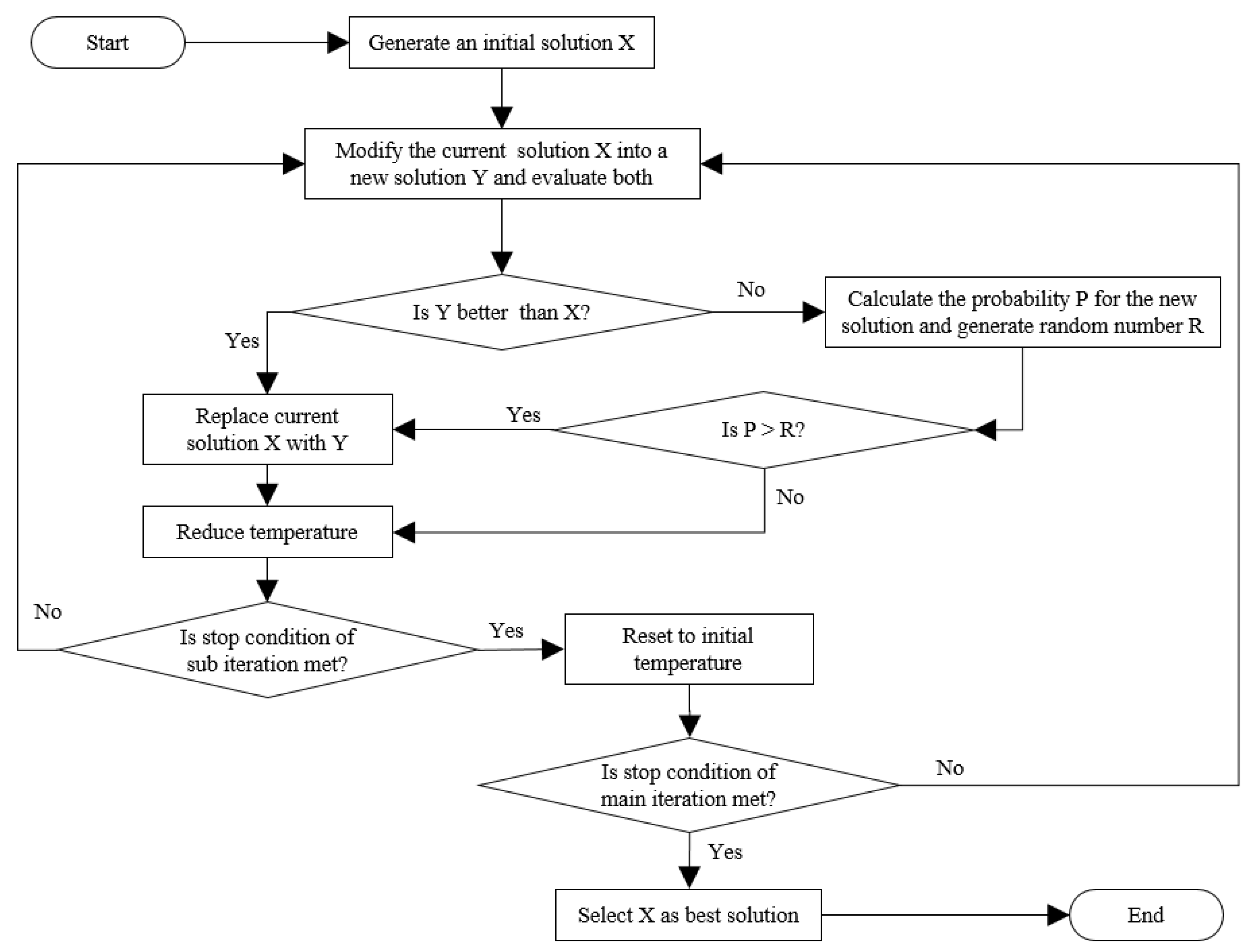
Table 6). The algorithm starts with an initial solution and for each subiteration it evaluates the current solution against a modified solution using the objective function, as illustrated in the flowchart of
Figure 6.
In this application of SAA, the initial solution is a coverage of the field where the constraints are obeyed, so it consists of a set of tours where the total demand of the tracks of each tour is less than the bin capacity. For each subiteration, a new candidate solution is generated, e.g., by swapping tours. If the cost of the new solution is lower than the cost of the current, then the current solution will be replaced by the new. Even if the new solution is not better than the current one, they may be exchanged with a certain probability. In this way, the algorithm can escape a development towards a local optimum. The probability
P is calculated with Equation (5), where T is the temperature and ∆C is the difference in cost of the solutions:
Hence, the probability of exchanging with an inferior solution is highest in the beginning of an annealing iteration when the temperature is high or when the cost difference is low.
2.7. The Ant Colony Optimization Algorithm
The Ant Colony Optimization (ACO) algorithm is another metaheuristic method inspired by a phenomenon in nature and, as the name implies, it simulates the foraging behavior of ants. Individual ants roam out from the colony to find food, more or less randomly, and they leave a trail of pheromones. When other ants find such a trail, they are likely to follow it, hence enforcing the pheromone trail. The pheromone scent evaporates over time, so in this way the shortest way to the best food sources will gradually be travelled most and have the strongest pheromone scent. This ant behavior was first suggested as a metaheuristic optimization method by [
32], and it has been applied in several types of optimization problems, including TSP [
32] and capacitated VRP [
21].
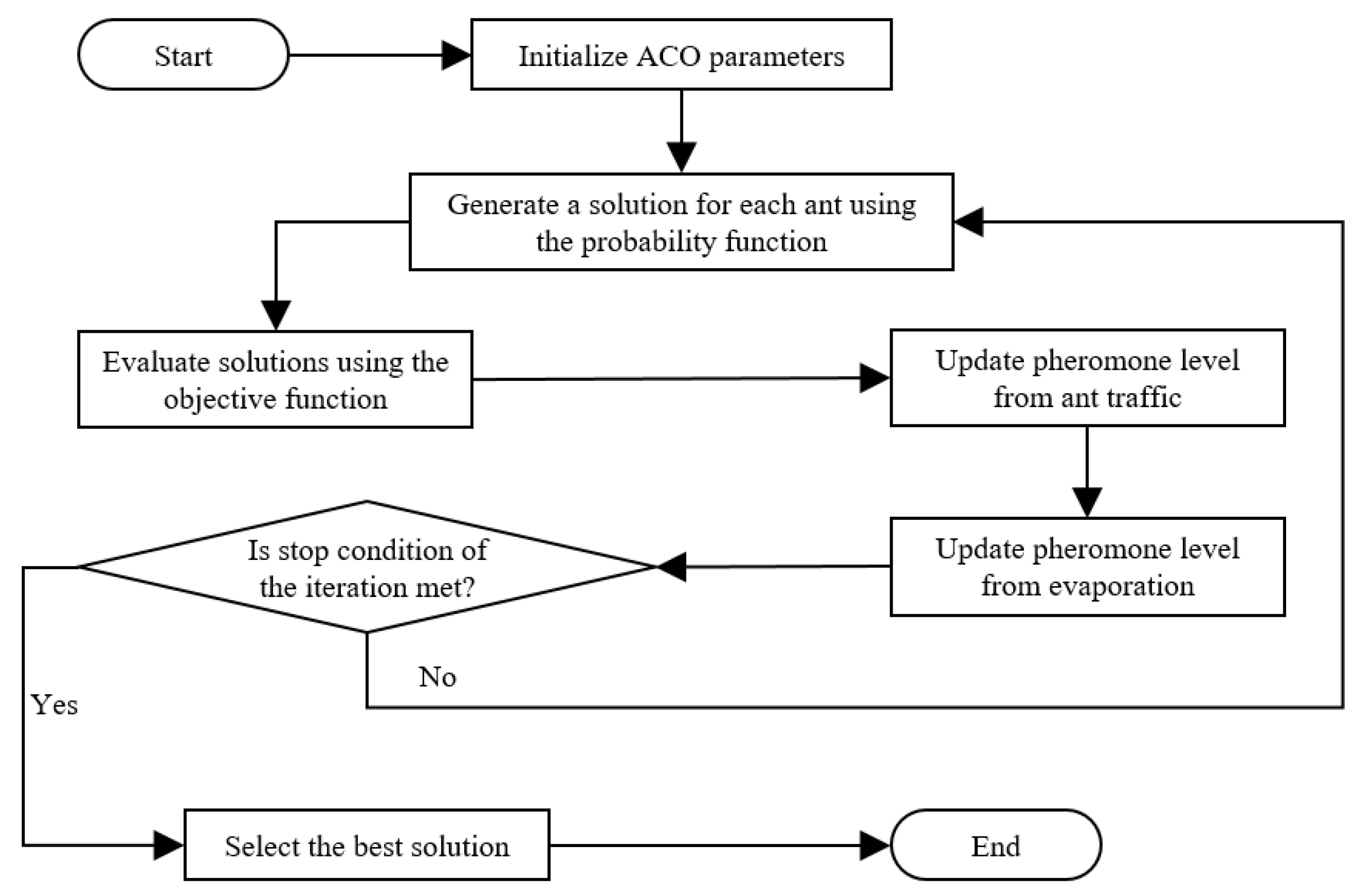
The ACO algorithm is governed by a set of parameters, shown in Table 8, including the number of ants and the number of iterations of the simulation. The flow of the algorithm is illustrated in
Figure 7. Each ant will generate a solution in each iteration, based on information maintained by the algorithm. This information includes a pheromone matrix with elements
τij corresponding to the current pheromone level for the path from node
i to
j. The information also includes an “attractiveness” matrix with elements
ηij representing the value of alternative reasons than pheromone scent to move from node
i to
j. The attractiveness is defined here as the reciprocal value of the corresponding element in the cost matrix (
Table A1 in
Appendix A):
ηij = 1
/Cij. The main information for an ant to choose the next node is the probability function, which gives the probability,
Pijk, that the
kth ant will move from node
i to node
j. The probability is calculated as a combination of the level of pheromone and attractiveness of the move from
i to
j, where the relative influence of the two reasons are determined with the two weights
α and
β, respectively (
Table 7). If
j has been visited already by ant
k then
Pijk = 0, otherwise it should be calculated based on the following Equation (6):
where
z is a member of the set of nodes not yet visited by ant
k. When each ant has made a solution, its value is calculated with the objective function. Then the pheromone matrix is updated in two steps: scent from recent ant traffic is added and evaporation is subtracted from the scent. The value of the pheromone evaporation rate
p is specified in
Table 7.


 ,
, 


