
A Retrofit Theory to Prevent Fatigue Crack Initiation in Aging Riveted Bridges Using Carbon Fiber-Reinforced Polymer Materials


Abstract
:
1. Introduction
1.1. State of the Art
1.2. Motivation
2. Fatigue Theories
2.1. Miner Linear Damage Accumulation
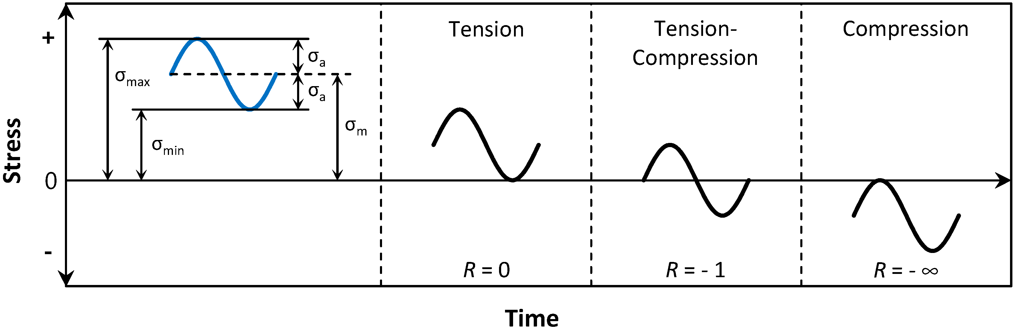
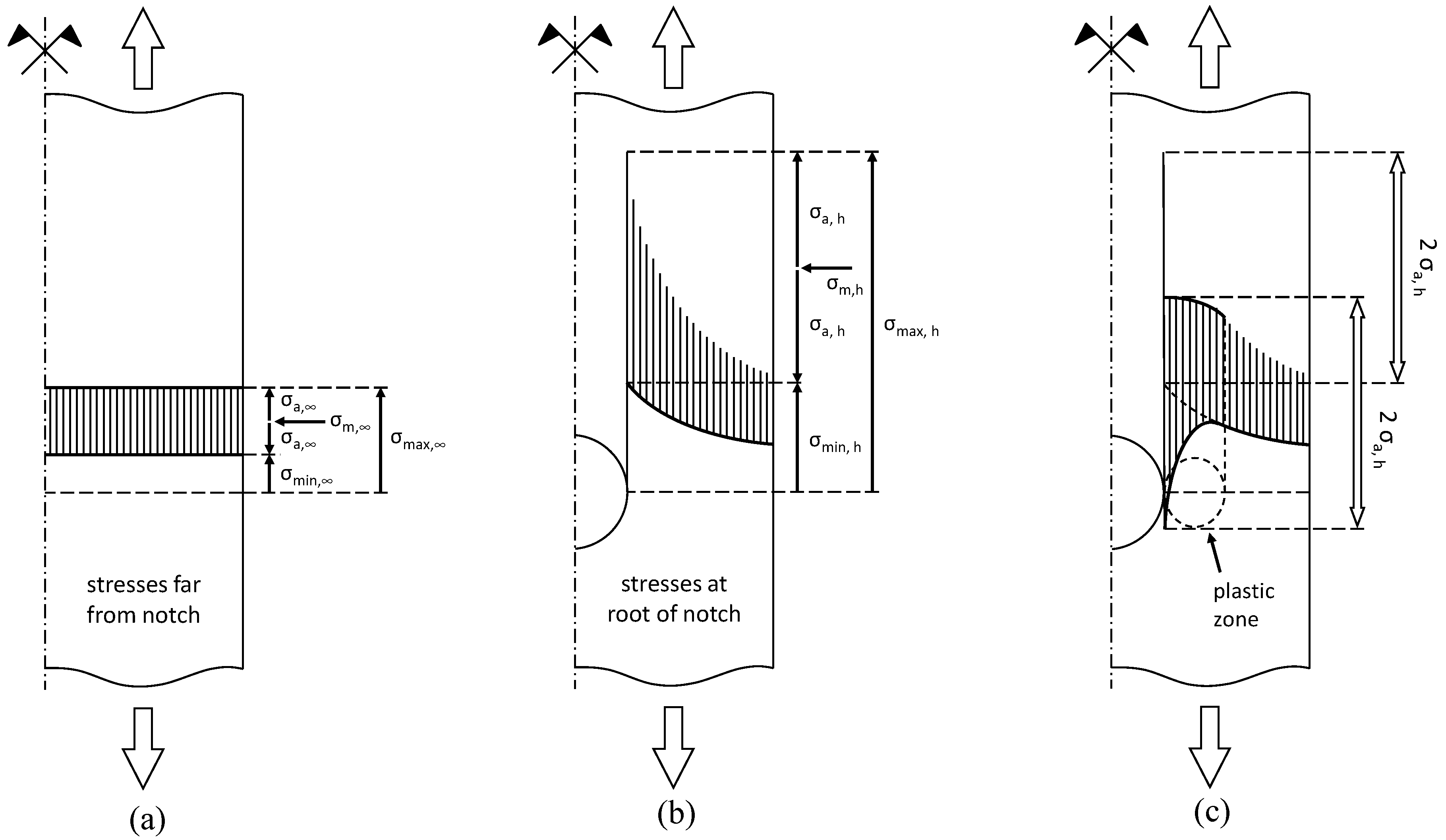
2.2. Stress Concentration at Notches
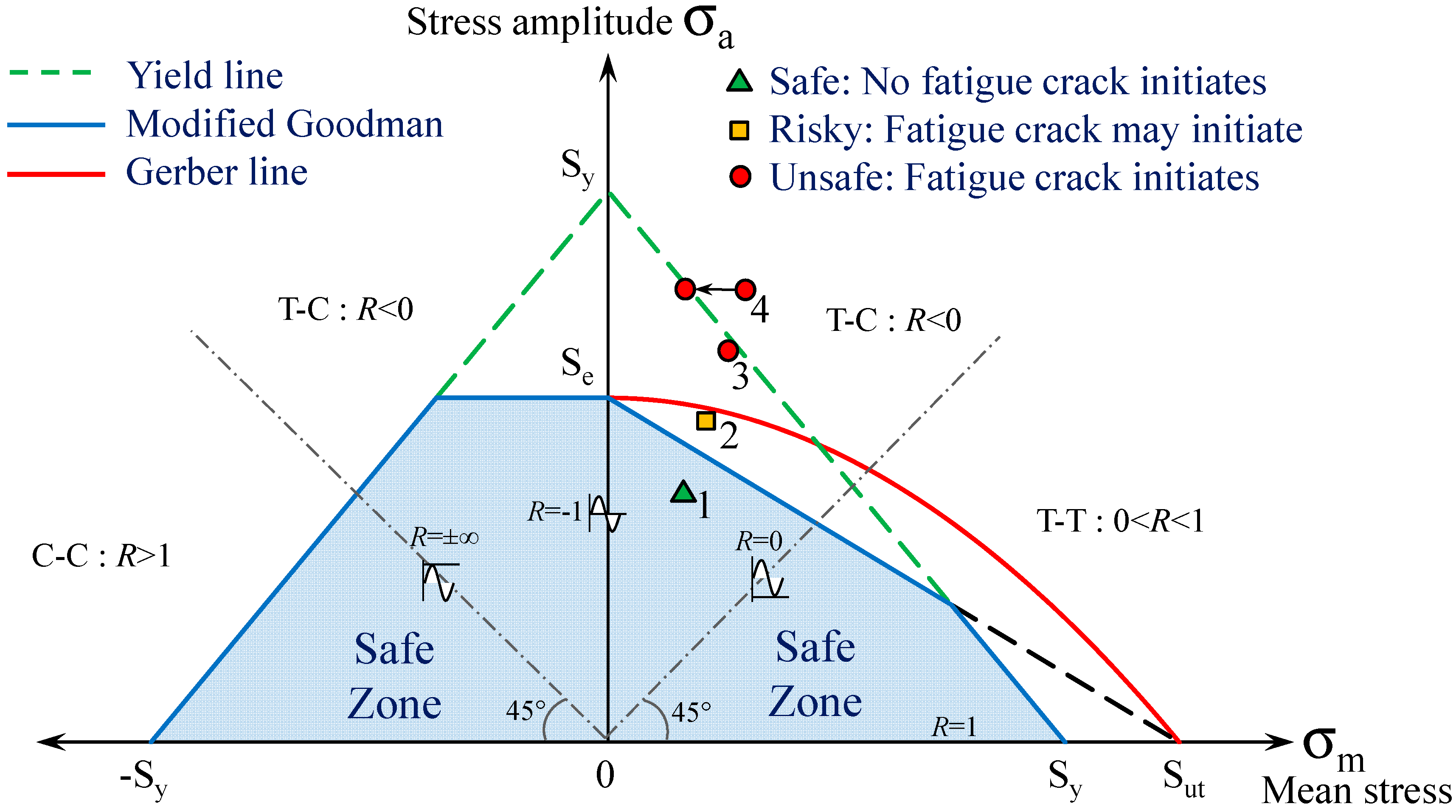
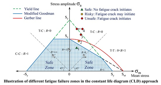
2.3. Constant Life Diagram (CLD) Approach
3. Strengthening Theory
4. Prediction Behavior of Retrofitted Beams
4.1. Metallic Beams Retrofitted with Bonded Carbon Fiber-Reinforced Polymer (CFRP) Plates
4.2. Beams Retrofitted with Un-Bonded CFRP Plates
5. Test Set-up, Specimens and Materials
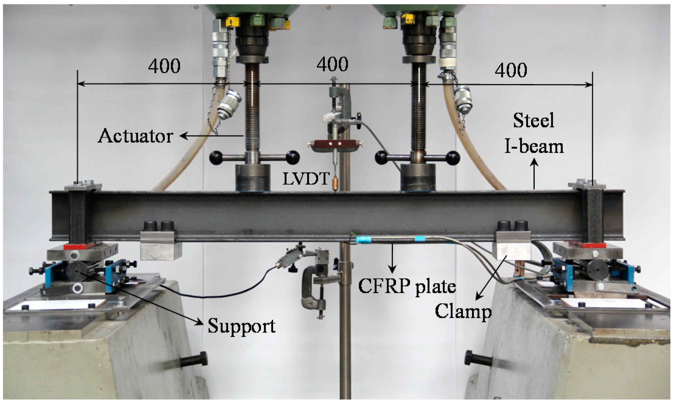
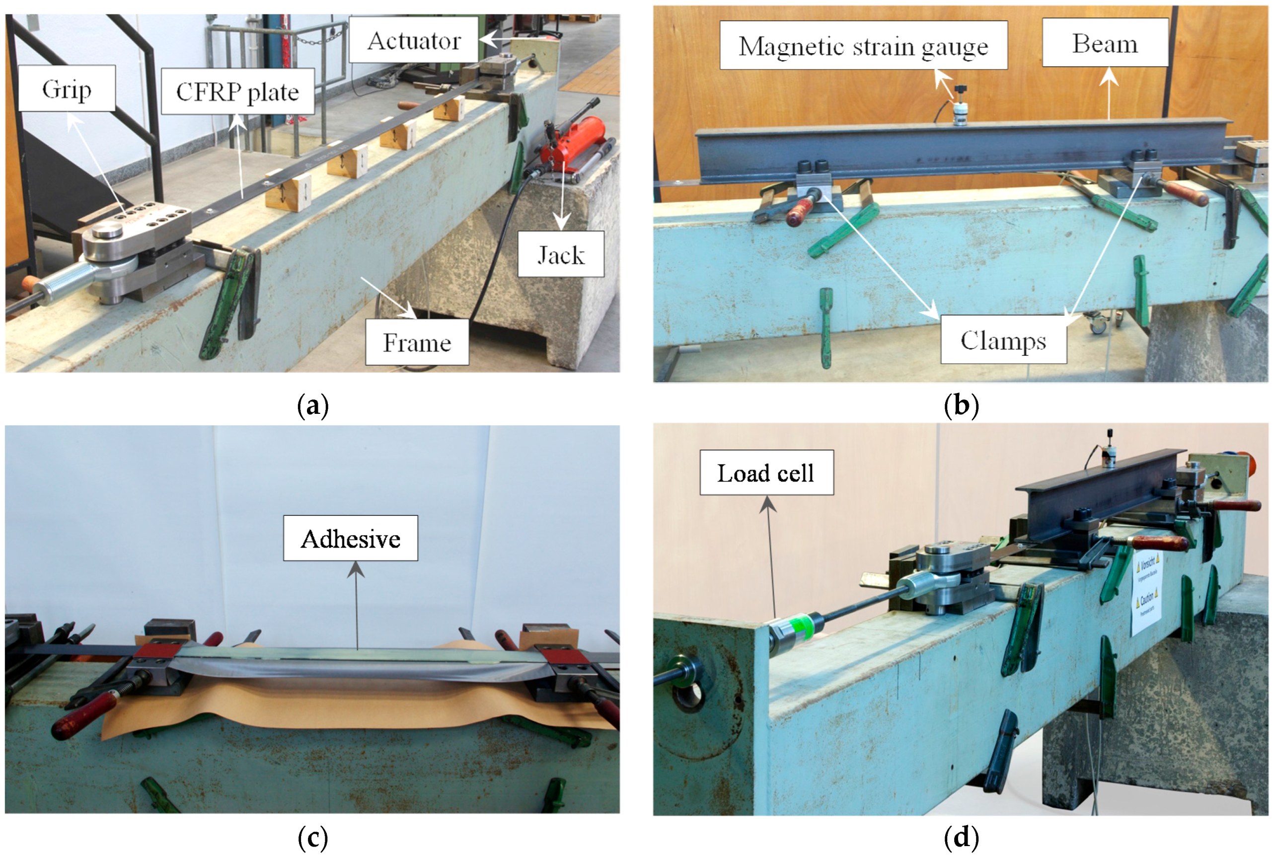
5.1. Test Set-up
5.2. Strengthening Technique
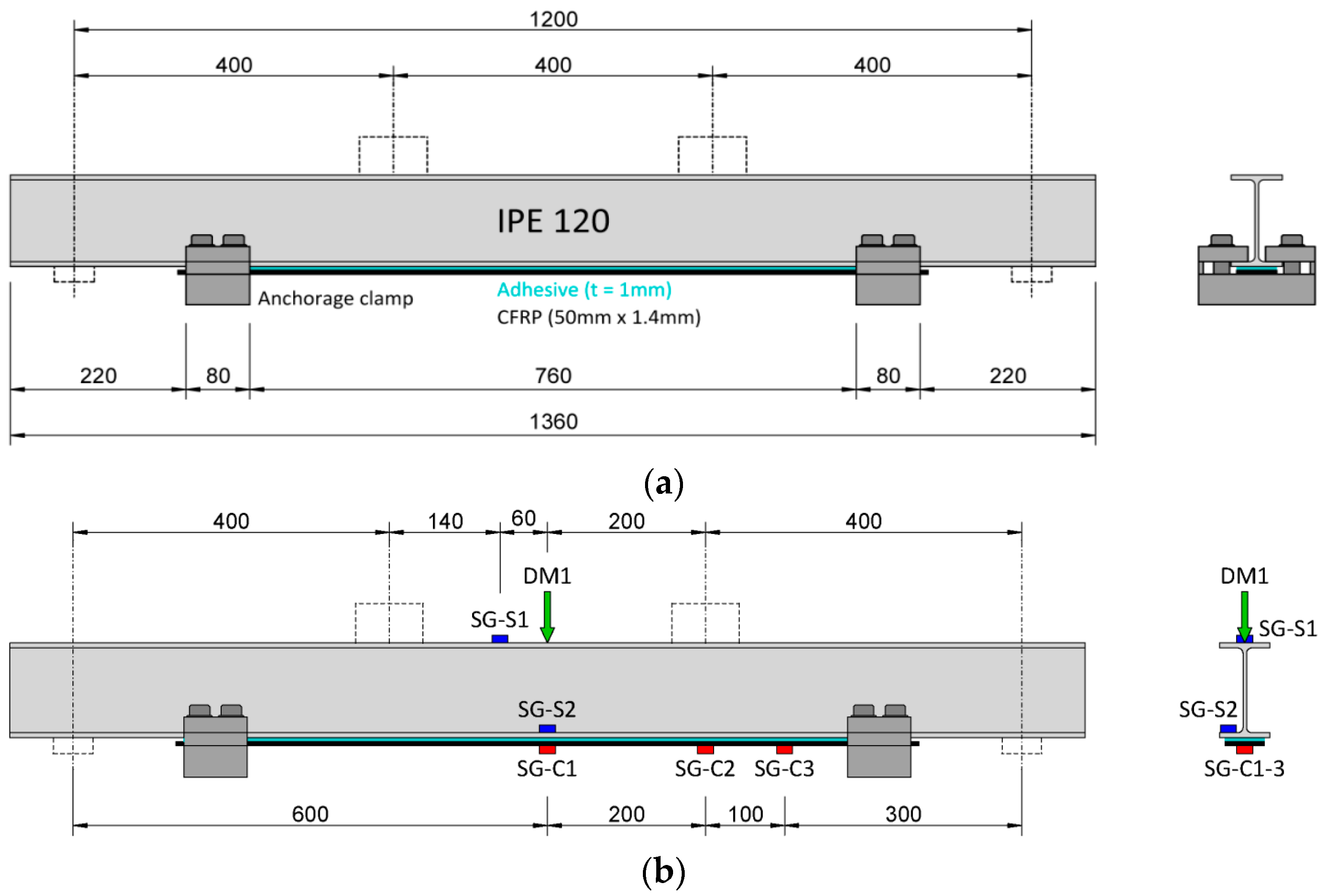
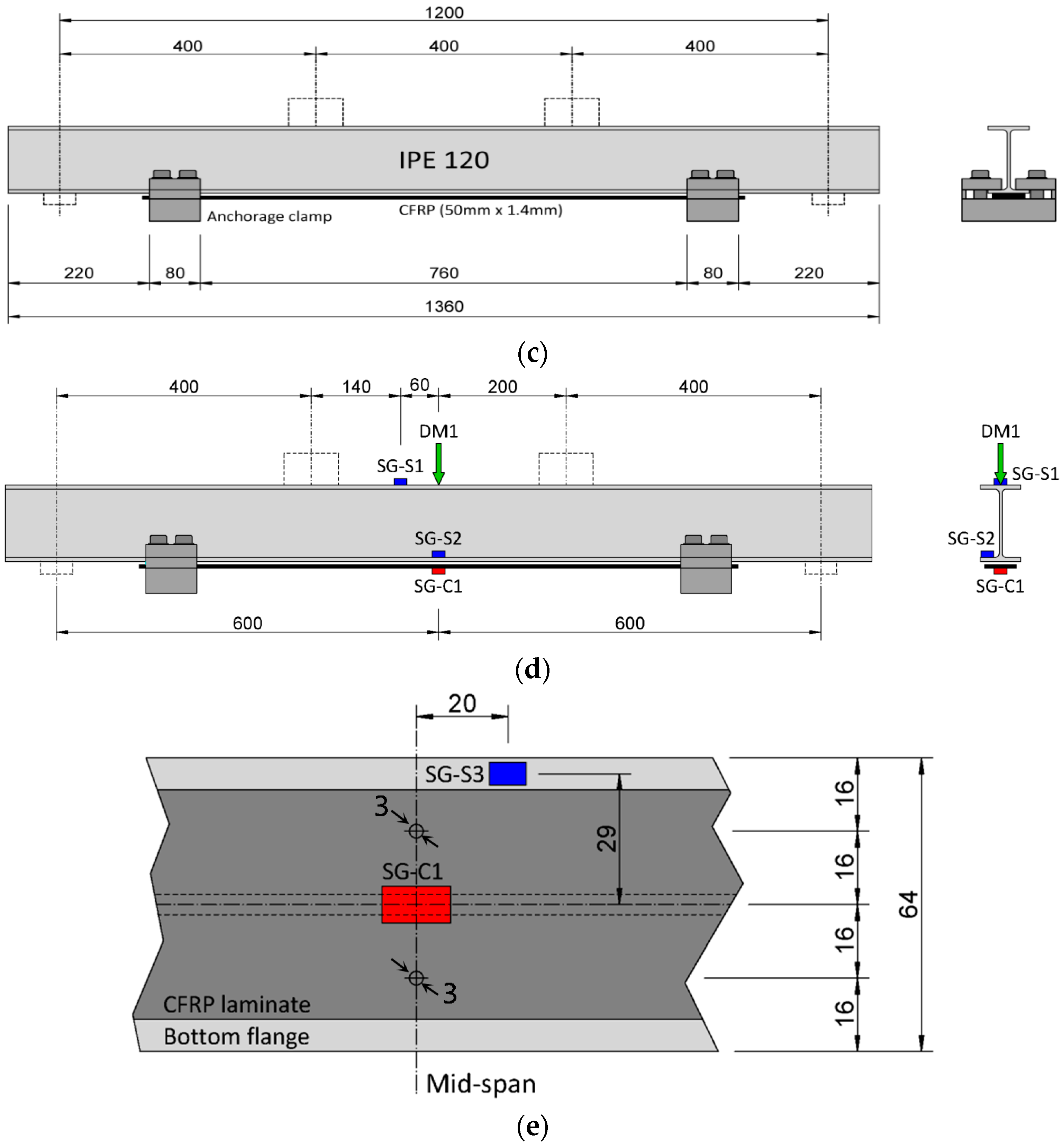
5.3. Specimens
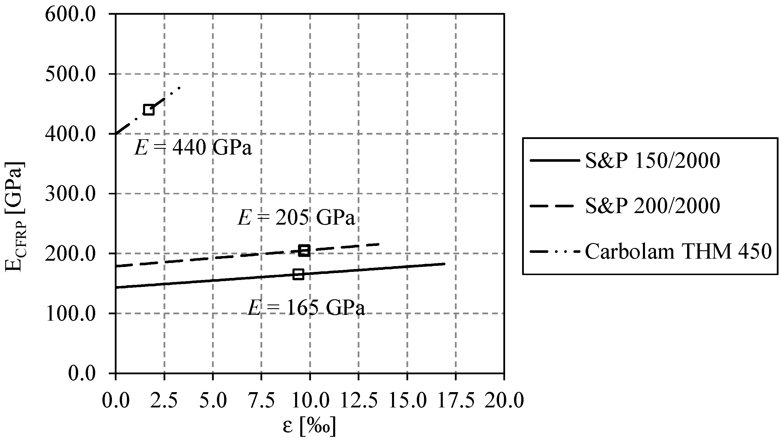
5.4. Materials
6. Test Plan and Results
6.1. Test Plan
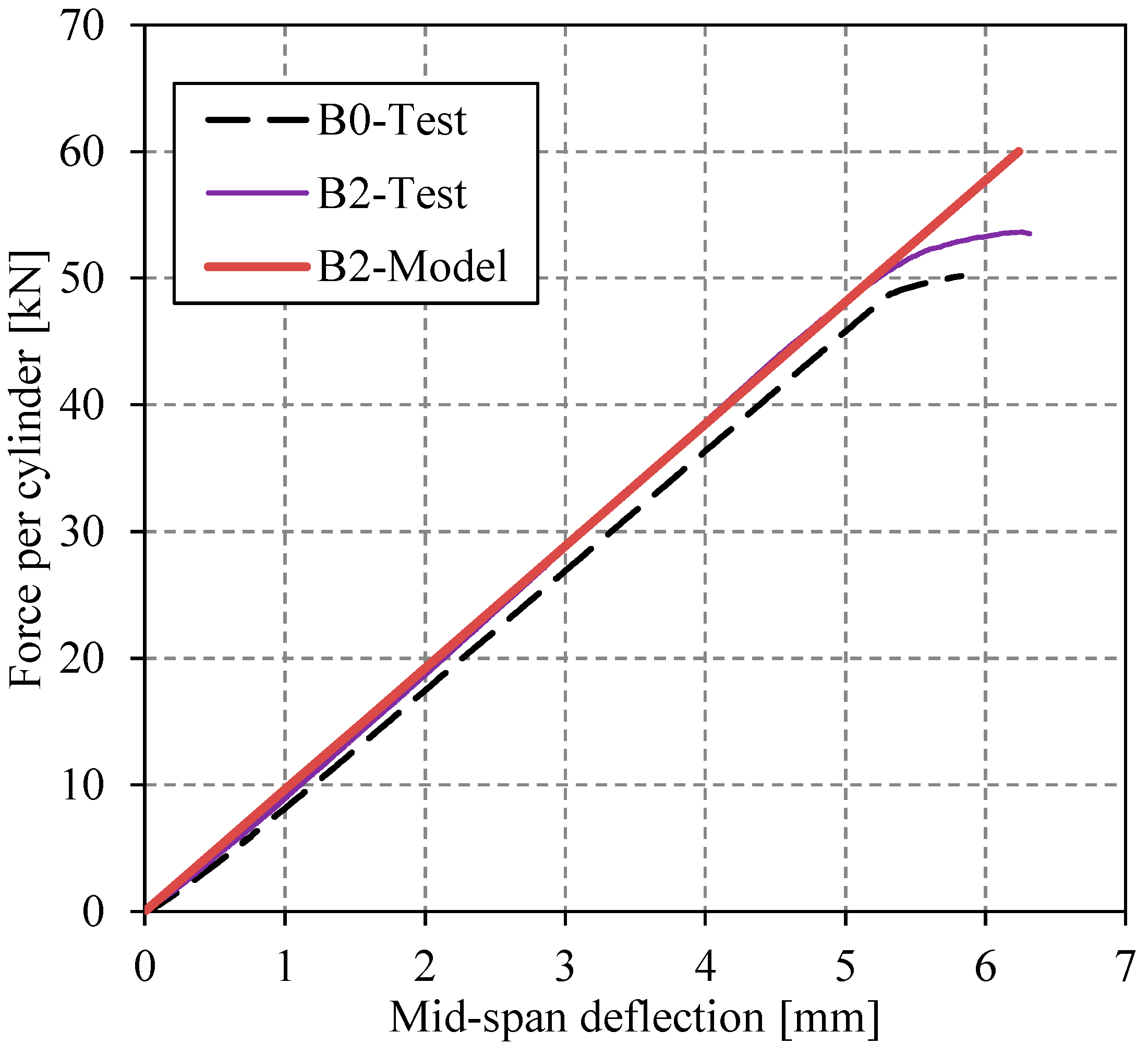
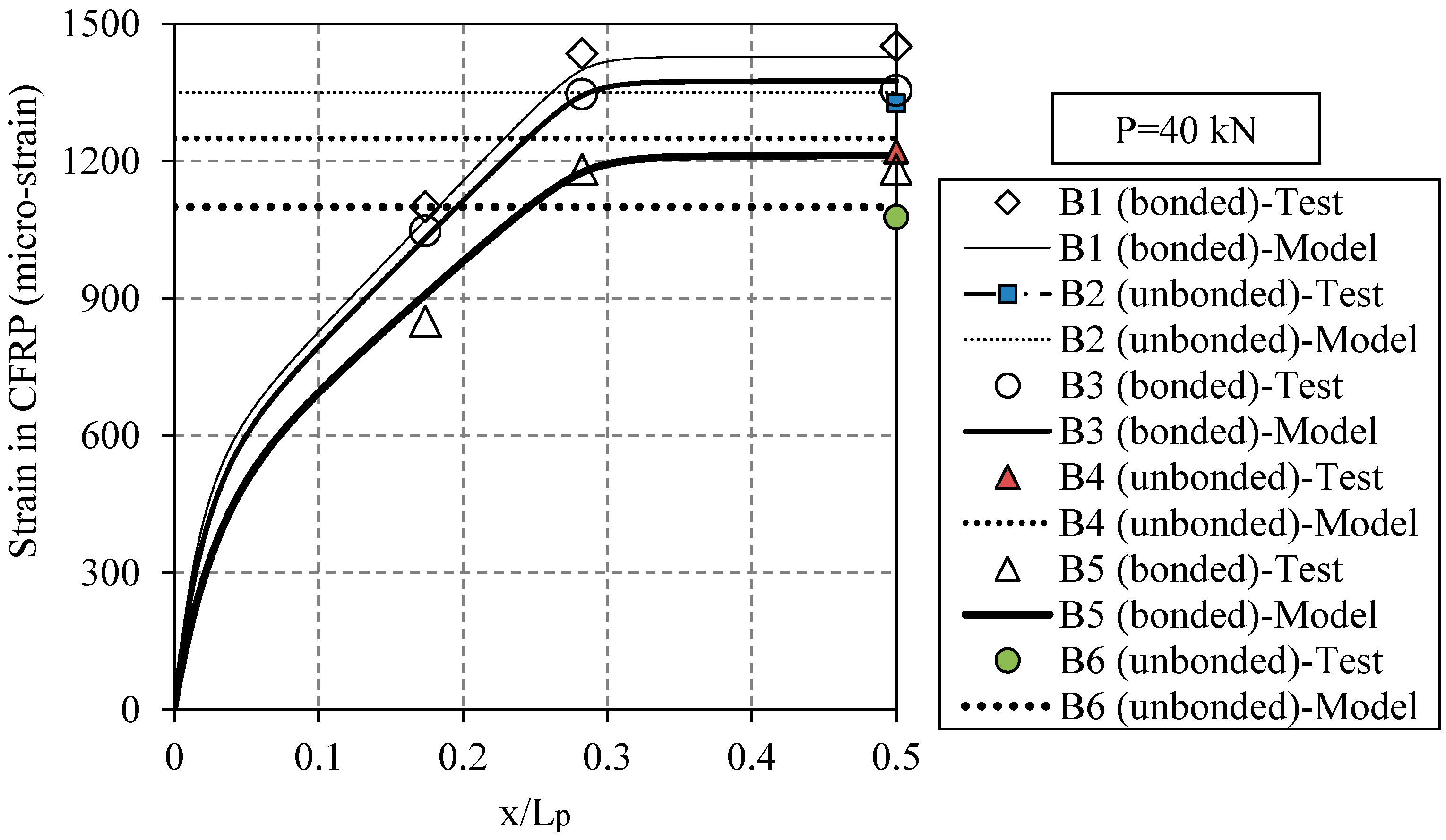
6.2. Static Test Results
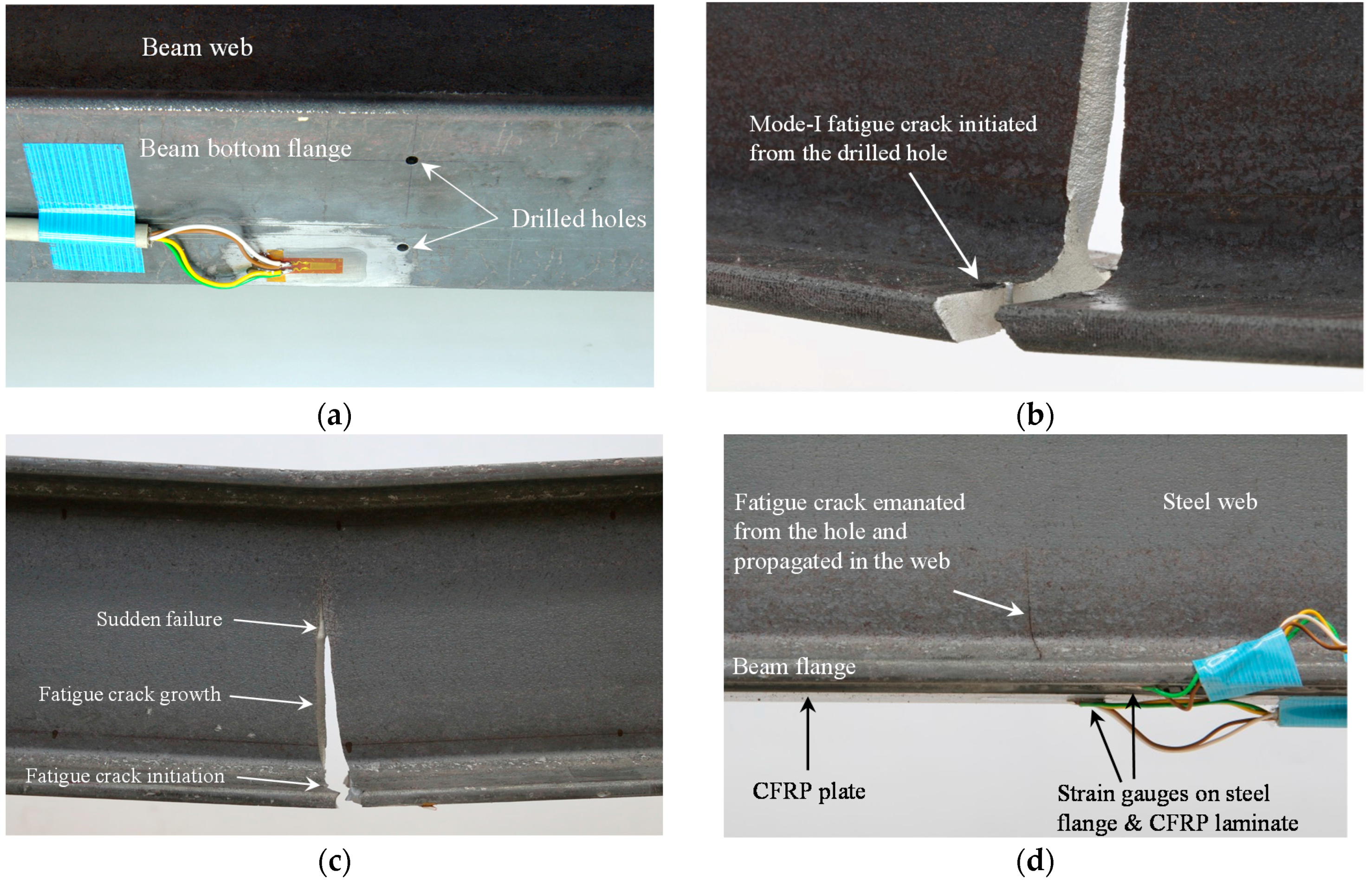
6.3. Fatigue Test Results
7. Conclusions
- Strengthening the steel beams using the un-bonded CFRP plates took less than half the time that was required to strengthen with the bonded CFRP plates. When strengthening with the un-bonded CFRP plates, there is no need for surface preparation or adhesive application, which can substantially reduce the time required and the cost of retrofitting.
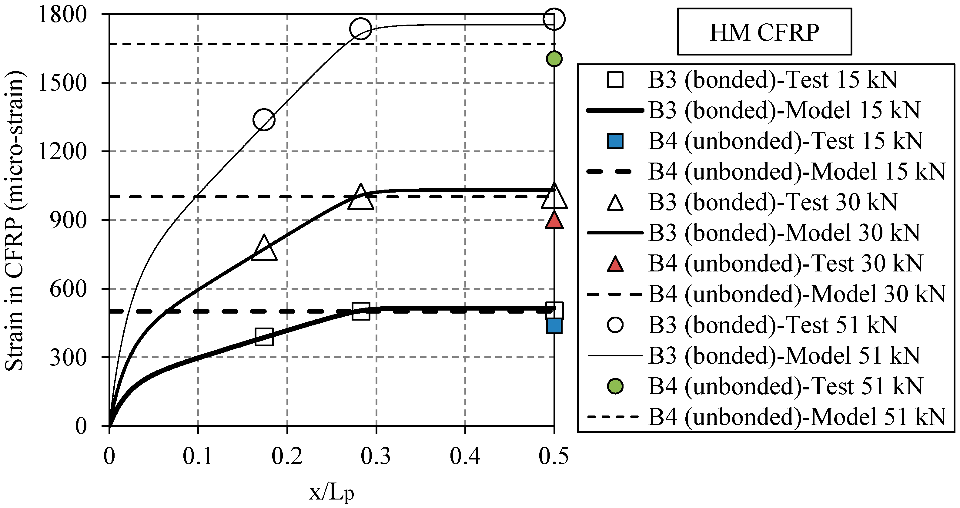
- By adhesively bonding the CFRP plate to the steel beams (i.e., the BR system), the relative displacements between the two components are minimized. Nevertheless, due to the elasticity of the adhesive layer, they are not exactly zero. As a result of this continuous connection, shear stress is transferred between the steel beam and the CFRP plate. In contrast, the UR system does not allow this stress transfer along the connection because there is no adhesive connection. Therefore, the BR and the UR systems produce differing behavior when shear stresses appear. Such shear stresses are only present if a shear force is acting on the system (e.g., in regions where the bending moment is not constant).
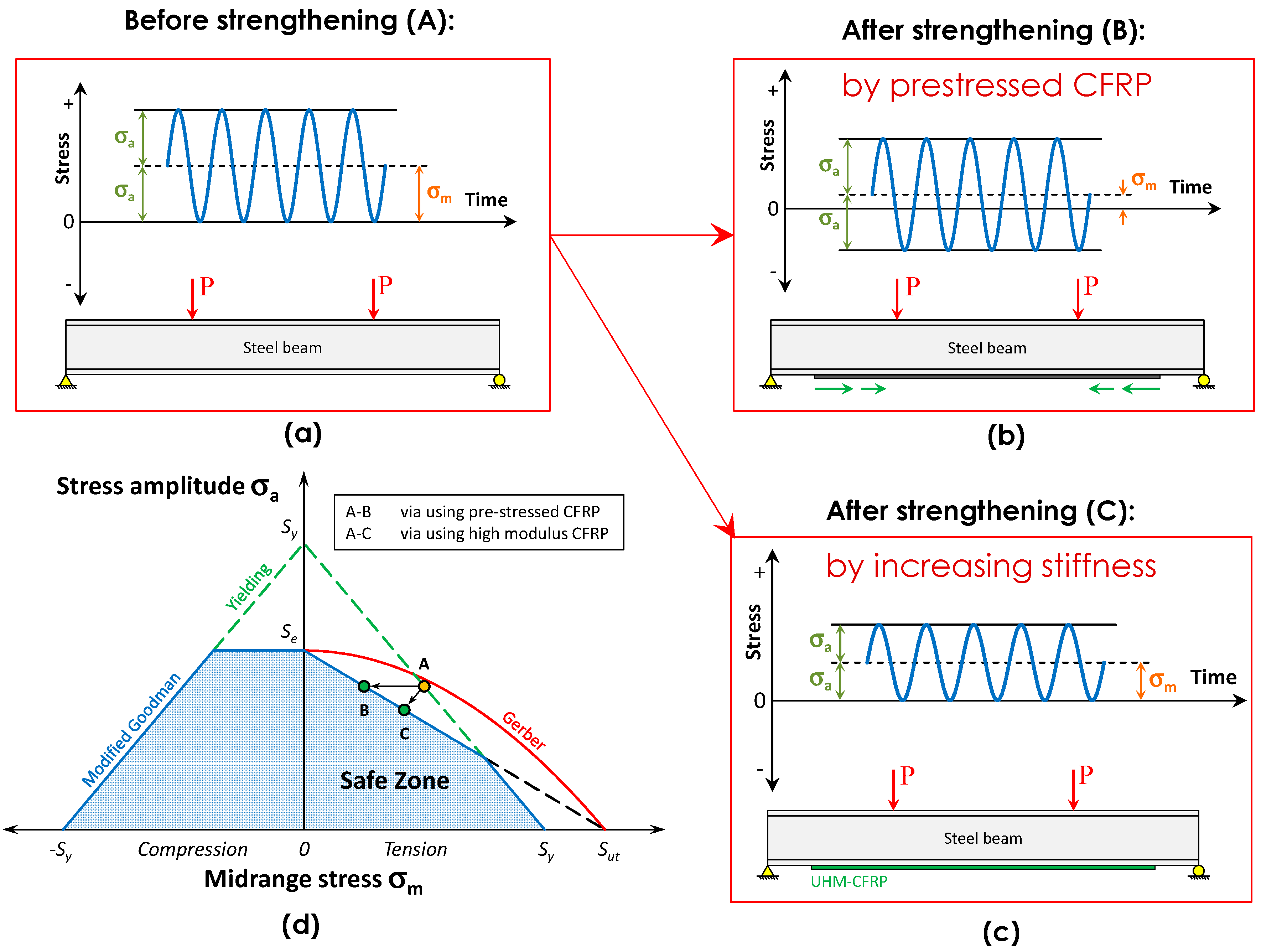
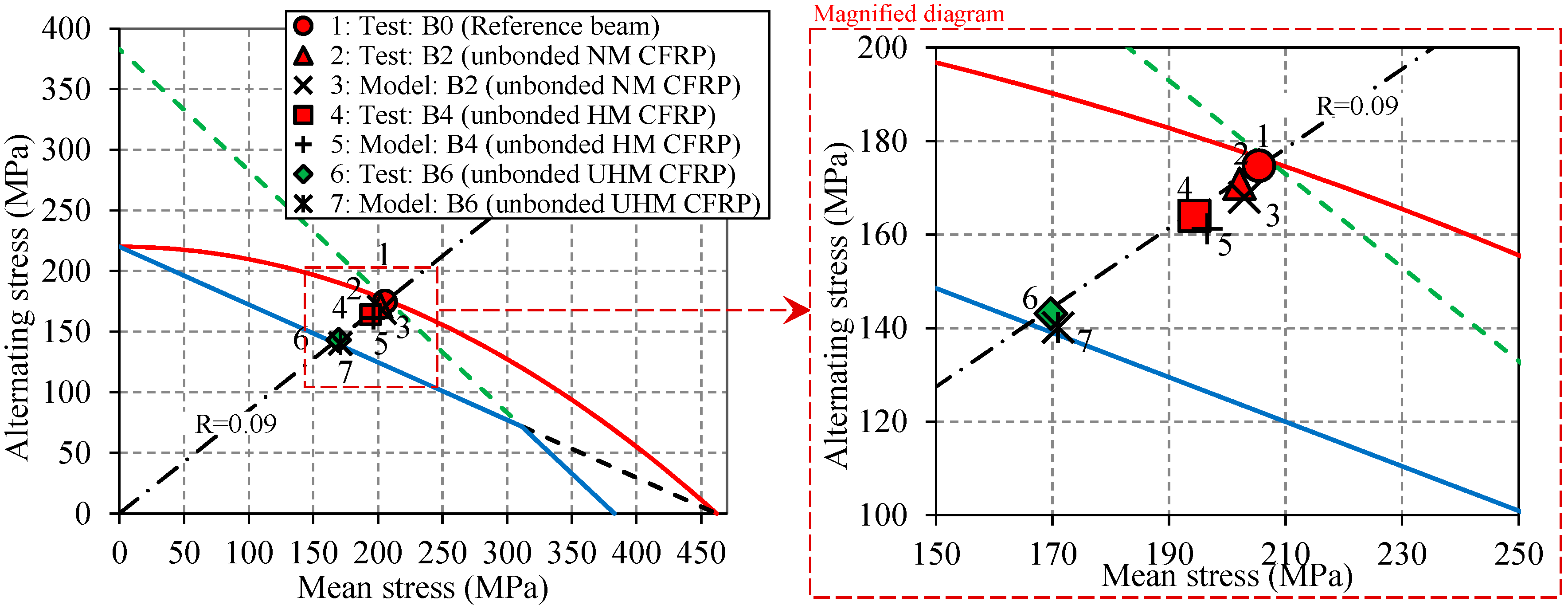
- Two mechanisms that can shift the detail from the risky finite-life regime to the safe infinite-life regime were explained. Mechanism 1: by applying a pre-stress force to an existing fatigue-susceptible detail, the mean stress level and the stress ratio, R, will be reduced such that the detail is shifted from the finite-life regime to the infinite-life regime. Mechanism 2: by increasing the stiffness of the beam (e.g., in using the UHM CFRP plates), the stress ratio, R, is preserved, but the mean and alternating stresses will be reduced such that the detail is shifted from the finite-life regime to the infinite-life regime.
- It was shown for the first time that the non-prestressed un-bonded UHM CFRP plates are efficient in preventing fatigue crack initiation in steel members. It is possible to use the presented retrofit approach to determine the CFRP Young’s modulus and the CFRP pre-stress to prevent future fatigue crack initiation.
Acknowledgments
Author Contributions
Conflicts of Interest
Abbreviations
| BR | Bonded retrofit |
| PBR | Pre-stressed bonded retrofit |
| UR | Un-bonded retrofit |
| PUR | Pre-stressed un-bonded retrofit |
| TPUR | Trapezoidal PUR |
| TriPUR | Triangular PUR |
| FPUR | Flat PUR |
| CPUR | Contact PUR |
| FCG | Fatigue crack growth |
| SIF | Stress intensity factor |
| CLD | Constant life diagram |
| NM | Normal modulus |
| HM | High modulus |
| UHM | Ultra-high modulus |
| CFRP | Carbon-fiber-reinforced polymer |
| LVDT | Linear variable differential transducer |
| NDT | Non-destructive testing |
| R | Stress ratio |
| D | Overall accumulated damage |
| FE | Finite element |
References
- Akesson, B. Fatigue Life of Riveted Railway Bridges. Ph.D. Thesis, Chalmers University of Technology, Göteborg, Sweden, 1994. [Google Scholar]
- Al-Emrani, M.; Kliger, R. Analysis of interfacial shear stresses in beams strengthened with bonded prestressed laminates. Compos. Part B Eng. 2006, 37, 265–272. [Google Scholar] [CrossRef]
- Colombi, P.; Bassetti, A.; Nussbaumer, A. Analysis of cracked steel members reinforced by pre-stress composite patch. Fatigue Fract. Eng. Mater. Struct. 2003, 26, 59–66. [Google Scholar] [CrossRef]
- Colombi, P.; Bassetti, A.; Nussbaumer, A. Crack growth induced delamination on steel members reinforced by prestressed composite patch. Fatigue Fract. Eng. Mater. Struct. 2003, 26, 429–437. [Google Scholar] [CrossRef]
- Dawood, M.; Rizkalla, S.; Sumner, E. Fatigue and overloading behavior of steel-concrete composite flexural members strengthened with high modulus CFRP materials. J. Compos. Constr. 2007, 11, 659–669. [Google Scholar] [CrossRef]
- Deng, J.; Lee, M.M.K.; Moy, S.S.J. Stress analysis of steel beams reinforced with a bonded CFRP plate. Compos. Struct. 2004, 65, 205–215. [Google Scholar] [CrossRef]
- Denton, S.Y. Analysis of stresses developed in FRP plated beams due to thermal effects. In Proceedings of the Conference on Composites in Civil Engineering, Hong Kong, China, 12–14 December 2001; pp. 527–536.
- El-Hacha, R.; Aly, M.Y.E. Anchorage system to prestress FRP laminates for flexural strengthening of steel-concrete composite girders. J. Compos. Constr. 2013, 17, 324–335. [Google Scholar] [CrossRef]
- Ghafoori, E. Interfacial stresses in beams strengthened with bonded prestressed plates. Eng. Struct. 2013, 46, 508–510. [Google Scholar] [CrossRef]
- Ghafoori, E.; Motavalli, M. Flexural and interfacial behavior of metallic beams strengthened by prestressed bonded plates. Compos. Struct. 2013, 101, 22–34. [Google Scholar] [CrossRef]
- Haghani, R.; Al-Emrani, M.; Kliger, R. Interfacial stress analysis of geometrically modified adhesive joints in steel beams strengthened with FRP laminates. Constr. Build. Mater. 2009, 23, 1413–1422. [Google Scholar] [CrossRef]
- Kim, Y.J.; Harries, K.A. Fatigue behavior of damaged steel beams repaired with CFRP strips. Eng. Struct. 2011, 33, 1491–1502. [Google Scholar] [CrossRef]
- Nozaka, K.; Shield, C.; Hajjar, J. Effective bond length of carbon-fiber-reinforced polymer strips bonded to fatigued steel bridge I-girders. J. Bridge Eng. 2005, 10, 195–205. [Google Scholar] [CrossRef]
- Rizkalla, S.; Dawood, M.; Schnerch, D. Development of a carbon fiber reinforced polymer system for strengthening steel structures. Compos. Part A Appl. Sci. Manuf. 2008, 39, 388–397. [Google Scholar] [CrossRef]
- Saadatmanesh, H.; Albrecht, P.; Ayyub, B.M. Guidelines for flexural design of prestressed composite beams. J. Struct. Eng. N. Y. 1989, 115, 2944–2961. [Google Scholar] [CrossRef]
- Schnerch, D.; Dawood, M.; Rizkalla, S.; Sumner, E.; Stanford, K. Bond behavior of CFRP strengthened steel structures. Adv. Struct. Eng. 2006, 9, 805–817. [Google Scholar] [CrossRef]
- Schnerch, D.; Rizkalla, S. Flexural strengthening of steel bridges with high modulus CFRP strips. J. Bridge Eng. 2008, 13, 192–201. [Google Scholar] [CrossRef]
- Tavakkolizadeh, M.; Saadatmanesh, H. Fatigue strength of steel girders strengthened with carbon fiber reinforced polymer patch. J. Struct. Eng. 2003, 129, 186–196. [Google Scholar] [CrossRef]
- Wu, C.; Zhao, X.L.; Al-Mahaidi, R.; Emdad, M.R.; Duan, W.H. Fatigue tests on steel plates with longitudinal weld attachment strengthened by ultra high modulus carbon fibre reinforced polymer plate. Fatigue Fract. Eng. Mater. Struct. 2013, 36, 1027–1038. [Google Scholar] [CrossRef]
- Wu, C.; Zhao, X.L.; Chiu, W.K.; Al-Mahaidi, R.; Duan, W.H. Effect of fatigue loading on the bond behaviour between uhm cfrp plates and steel plates. Compos. B Eng. 2013, 50, 344–353. [Google Scholar] [CrossRef]
- Täljsten, B.; Hansen, C.S.; Schmidt, J.W. Strengthening of old metallic structures in fatigue with prestressed and non-prestressed CFRP laminates. Constr. Build. Mater. 2009, 23, 1665–1677. [Google Scholar] [CrossRef]
- Huawen, Y.; König, C.; Ummenhofer, T.; Shizhong, Q.; Plum, R. Fatigue performance of tension steel plates strengthened with prestressed CFRP laminates. J. Compos. Constr. 2010, 14, 609–615. [Google Scholar] [CrossRef]
- Ghafoori, E.; Motavalli, M. Analytical calculation of stress intensity factor of cracked steel I-beams with experimental analysis and 3D digital image correlation measurements. Eng. Fract. Mech. 2011, 78, 3226–3242. [Google Scholar] [CrossRef]
- Aljabar, N.J.; Zhao, X.L.; Al-Mahaidi, R.; Ghafoori, E.; Motavalli, M.; Powers, N. Effect of crack orientation on fatigue behaviour of CFRP-strengthened steel plates. Compos. Struct. 2016, 152, 295–305. [Google Scholar] [CrossRef]
- Ghafoori, E.; Motavalli, M.; Botsis, J.; Herwig, A.; Galli, M. Fatigue strengthening of damaged metallic beams using prestressed unbonded and bonded CFRP plates. Int. J. Fatigue 2012, 44, 303–315. [Google Scholar] [CrossRef]
- Ghafoori, E.; Schumacher, A.; Motavalli, M. Fatigue behavior of notched steel beams reinforced with bonded CFRP plates: Determination of prestressing level for crack arrest. Eng. Struct. 2012, 45, 270–283. [Google Scholar] [CrossRef]
- Ghafoori, E.; Motavalli, M. Lateral-torsional buckling of steel I-beams retrofitted by bonded and un-bonded CFRP laminates with different pre-stress levels: Experimental and numerical study. Constr. Build. Mater. 2015, 76, 194–206. [Google Scholar] [CrossRef]
- Ghafoori, E.; Motavalli, M. Normal, high and ultra-high modulus CFRP laminates for bonded and un-bonded strengthening of steel beams. Mater. Des. 2015, 67, 232–243. [Google Scholar] [CrossRef]
- Ghafoori, E. Fatigue Strengthening of Metallic Members Using Un-Bonded and Bonded CFRP Laminates. Ph.D. Thesis, ETH-Zurich, Zurich, Switzerland, 2015. Availablie online: http://dx.doi.org/10.3929/ethz-a-010453130 (accessed on 12 June 2015). [Google Scholar]
- Ghafoori, E.; Motavalli, M.; Zhao, X.L.; Nussbaumer, A.; Fontana, M. Fatigue design criteria for strengthening metallic beams with bonded CFRP plates. Eng. Struct. 2015, 101, 542–557. [Google Scholar] [CrossRef]
- Ghafoori, E.; Motavalli, M. Innovative CFRP-prestressing system for strengthening metallic structures. J. Compos. Constr. 2015, 19, 04015006. [Google Scholar] [CrossRef]
- Ghafoori, E.; Motavalli, M.; Nussbaumer, A.; Herwig, A.; Prinz, G.; Fontana, M. Determination of minimum CFRP pre-stress levels for fatigue crack prevention in retrofitted metallic beams. Eng. Struct. 2015, 84, 29–41. [Google Scholar] [CrossRef]
- Ghafoori, E.; Motavalli, M.; Nussbaumer, A.; Herwig, A.; Prinz, G.S.; Fontana, M. Design criterion for fatigue strengthening of riveted beams in a 120-year-old railway metallic bridge using pre-stressed CFRP plates. Compos. Part B Eng. 2015, 68, 1–13. [Google Scholar] [CrossRef]
- Ghafoori, E.; Prinz, G.S.; Mayor, E.; Nussbaumer, A.; Motavalli, M.; Herwig, A.; Fontana, M. Finite element analysis for fatigue damage reduction in metallic riveted bridges using pre-stressed CFRP plates. Polymers 2014, 6, 1096–1118. [Google Scholar] [CrossRef]
- Colombi, P.; Bassetti, A.; Nussbaumer, A. Delamination effects on cracked steel members reinforced by prestressed composite patch. Theor. Appl. Fract. Mech. 2003, 39, 61–71. [Google Scholar] [CrossRef]
- Budynas, R.G.; Nisbett, J.K. Shigley’s Mechanical Engineering Design; McGraw-Hill: New York, NY, USA, 2008. [Google Scholar]
- Klubberg, F.; Klopfer, I.; Broeckmann, C.; Berchtold, R.; Beiss, P. Fatigue testing of materials and components under mean load conditions. An. Mec. Fract. 2011, 1, 419–424. [Google Scholar]
- Kianmofrad, F.; Ghafoori, E.; Elyasi, M.M.; Motavalli, M.; Rahimian, M. Analytical solutions for the flexural behavior of steel and aluminum beams strengthened with different pre-stressed un-bonded retrofit systems. Compos. Struct. 2016. submitted for publication. [Google Scholar]
- Beetz, C.P. Strain-induced stiffening of carbon fibres. Fibre Sci. Technol. 1982, 16, 219–229. [Google Scholar] [CrossRef]
- Fernando, D.; Schumacher, A.; Motavalli, M.; Teng, J.G.; Yu, T.; Ghafoori, E. Fatigue strengthening of cracked steel beams with CFRP plates. In Proceedings of the ASME International Mechanical Engineering Congress and Exposition, Vancouver, BC, Canada, 12–18 November 2010; Volume 9, pp. 271–276.
- Fernando, N.D. Bond Behaviour and Debonding Failures in CFRP-Strengthened Steel Members; The Hong Kong Polytechnic University: Kowloon, Hong Kong, 2010. [Google Scholar]


| Steel grade | Yield strength | Tensile strength | Young’s modulus |
|---|---|---|---|
| fy,s (MPa) | fu,s (MPa) | Es (MPa) | |
| S235JR | 383 | 462 | 199,300 |
| Type | Width | Thickness | Cross-sectional area |
|---|---|---|---|
| bCFRP (mm) | tCFRP (mm) | ACFRP (mm2) | |
| NM CFRP | 50 | 1.4 | 70 |
| HM CFRP | 50 | 1.4 | 70 |
| UHM CFRP | 50 | 1.4 | 70 |
| Type | Tensile strength | Ultimate tensile strain | Young’s modulus | |||
|---|---|---|---|---|---|---|
| fu,CFRP (MPa) | εu,CFRP (%) | ECFRP (MPa) | ||||
| Mean | Min. | Mean | Min. | Mean | Min. | |
| NM CFRP | – | 2800 | – | 1.70 | – | 165,000 |
| HM CFRP | – | 2800 | – | 1.35 | – | 205,000 |
| UHM CFRP | 1500 | 1200 | 0.34 | 0.27 | 460,000 | 440,000 |
| Type | Lap shear strength (Steel to Steel) | Lap shear strength (CFRP to CFRP) |
|---|---|---|
| τu (MPa) | τu (MPa) | |
| Araldite® AW 106 with Hardener HV 953 U | 25 | 19 |
| Specimen | CFRP type | System type |
|---|---|---|
| B0 | – | – |
| B1 | Normal modulus | Bonded |
| B2 | Normal modulus | Un-bonded |
| B3 | High modulus | Bonded |
| B4 | High modulus | Un-bonded |
| B5 | Ultra-high modulus | Bonded |
| B6 | Ultra-high modulus | Un-bonded |
| Specimen | Strengthening scheme | Laminate type | No. of cycles to crack initiation | Failure mode |
|---|---|---|---|---|
| B0 | Unstrengthened | – | 450,000 | Crack initiation |
| B2 | Un-bonded | NM CFRP | 1,120,000 | Crack initiation |
| B4 | Un-bonded | HM CFRP | 1,500,000 | Crack initiation |
| B6 | Un-bonded | UHM CFRP | 2,000,000 | Run-out |
© 2016 by the authors. Licensee MDPI, Basel, Switzerland. This article is an open access article distributed under the terms and conditions of the Creative Commons Attribution (CC-BY) license ( http://creativecommons.org/licenses/by/4.0/).
Share and Cite
Ghafoori, E.; Motavalli, M. A Retrofit Theory to Prevent Fatigue Crack Initiation in Aging Riveted Bridges Using Carbon Fiber-Reinforced Polymer Materials. Polymers 2016, 8, 308. https://doi.org/10.3390/polym8080308
Ghafoori E, Motavalli M. A Retrofit Theory to Prevent Fatigue Crack Initiation in Aging Riveted Bridges Using Carbon Fiber-Reinforced Polymer Materials. Polymers. 2016; 8(8):308. https://doi.org/10.3390/polym8080308
Chicago/Turabian StyleGhafoori, Elyas, and Masoud Motavalli. 2016. "A Retrofit Theory to Prevent Fatigue Crack Initiation in Aging Riveted Bridges Using Carbon Fiber-Reinforced Polymer Materials" Polymers 8, no. 8: 308. https://doi.org/10.3390/polym8080308
APA StyleGhafoori, E., & Motavalli, M. (2016). A Retrofit Theory to Prevent Fatigue Crack Initiation in Aging Riveted Bridges Using Carbon Fiber-Reinforced Polymer Materials. Polymers, 8(8), 308. https://doi.org/10.3390/polym8080308