
Study of Polymer Matrix Degradation Behavior in CFRP Short Pulsed Laser Processing

Abstract
:
1. Introduction
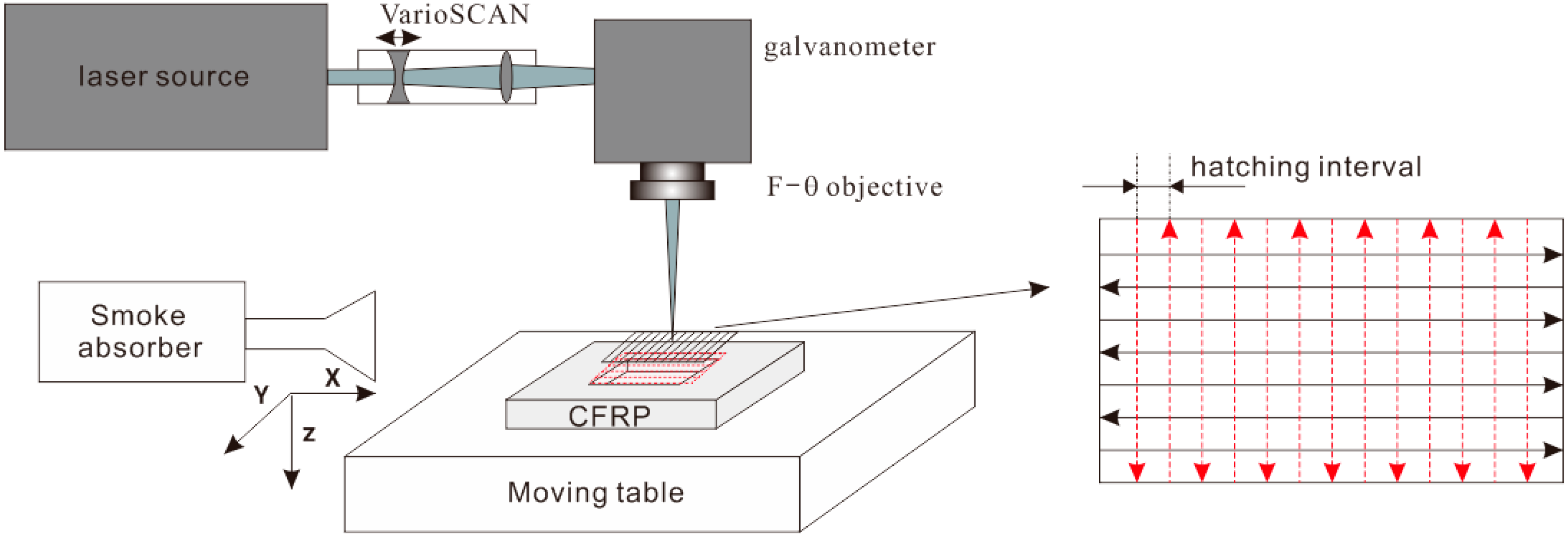
2. Experimental Setup
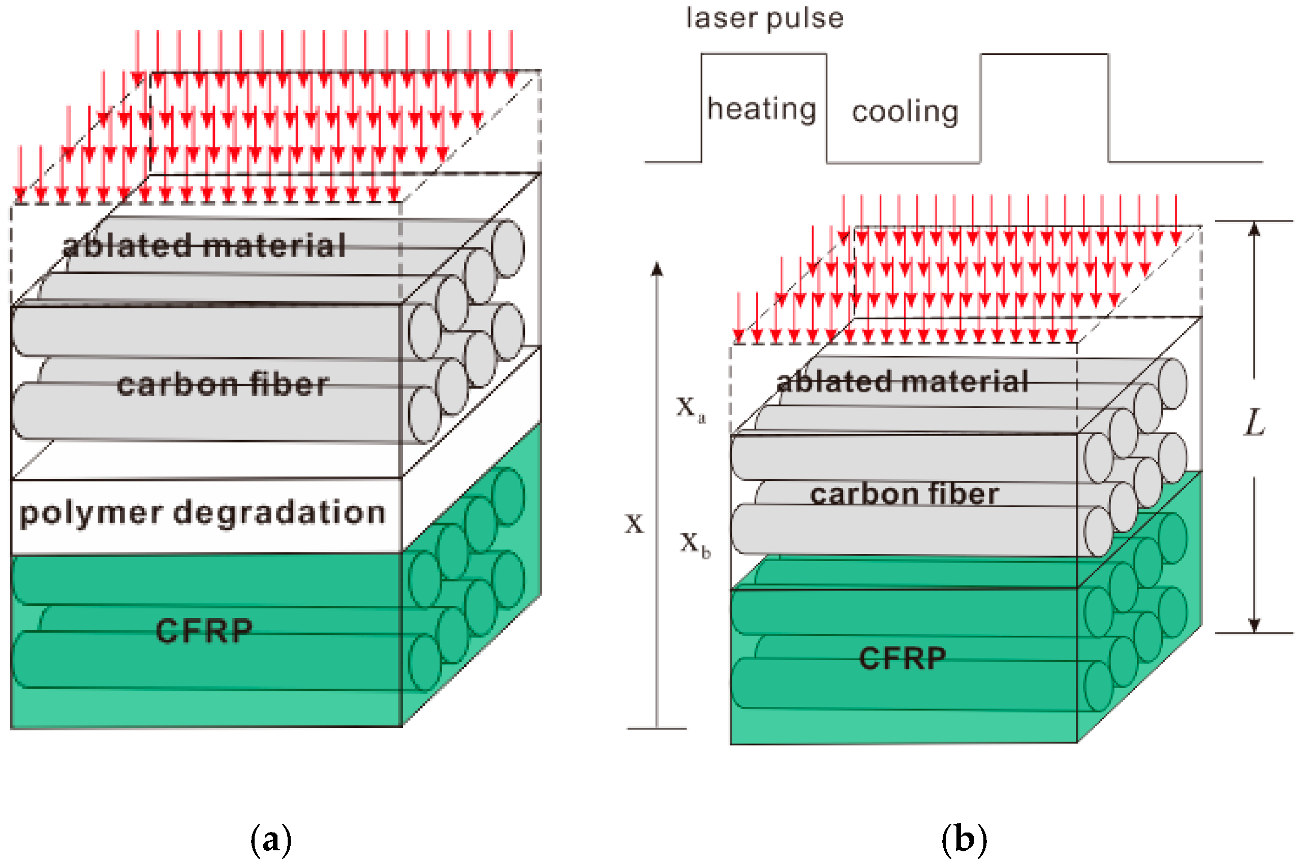
3. Model Formulation
3.1. Polymer Degradation Mechanism
3.2. Heat Transport
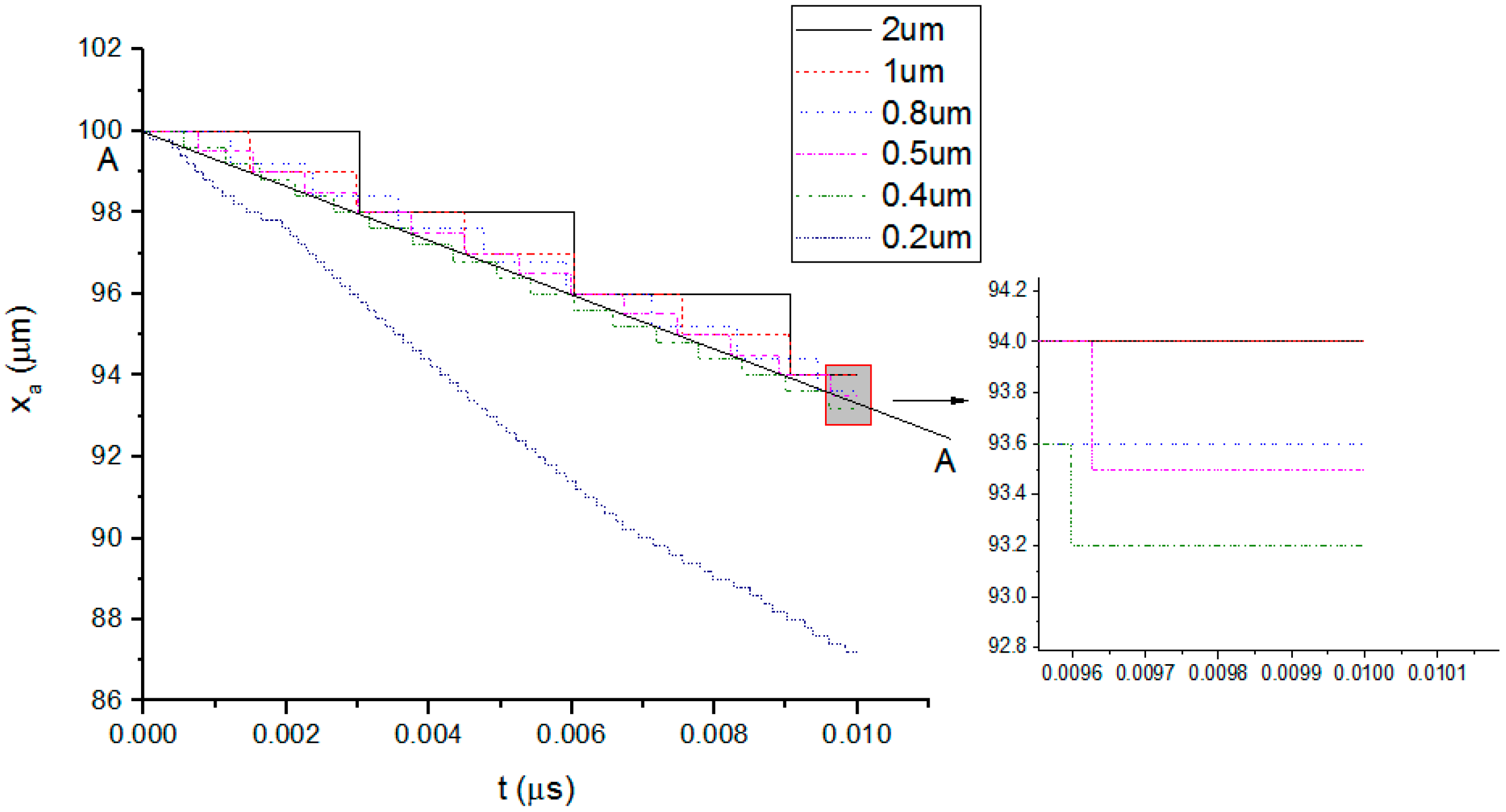
3.3. Mass Transport
4. Results and Discussion
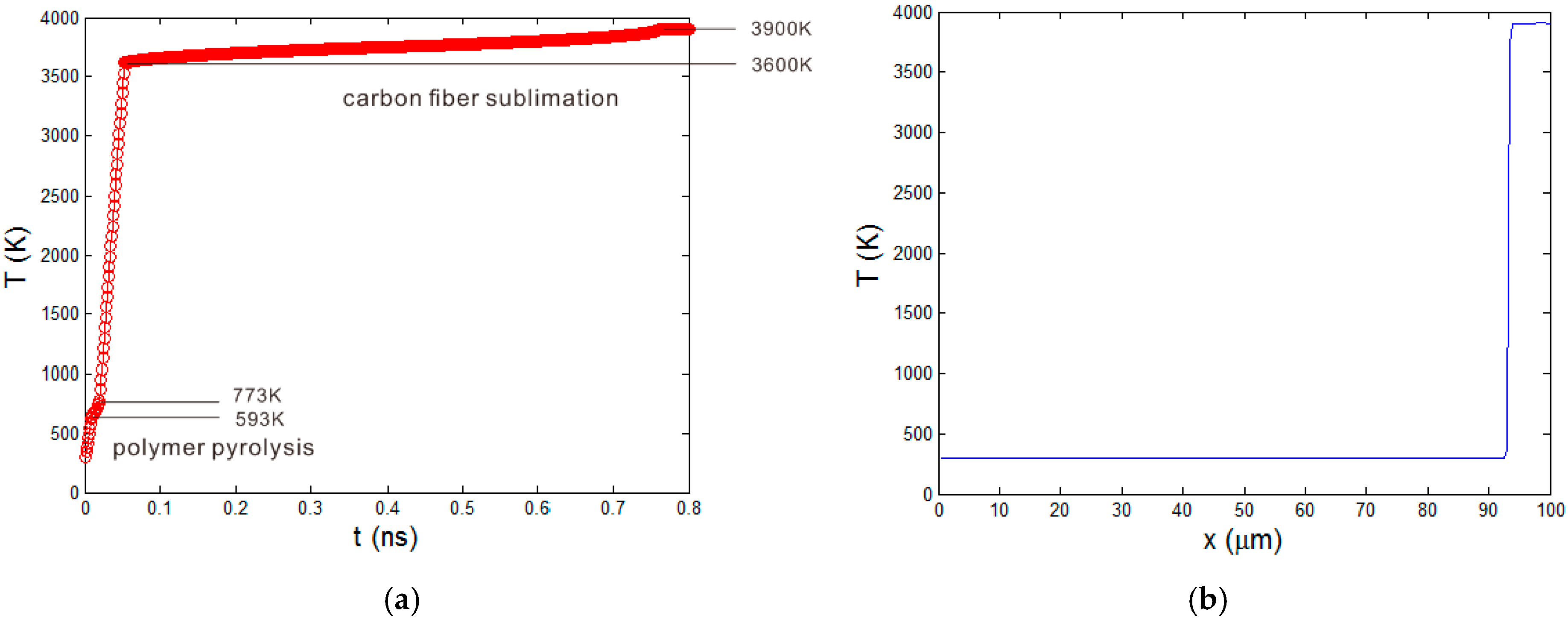
4.1. Characteristics of 10 ns Short Pulsed Laser
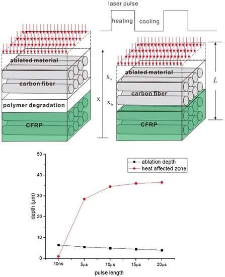
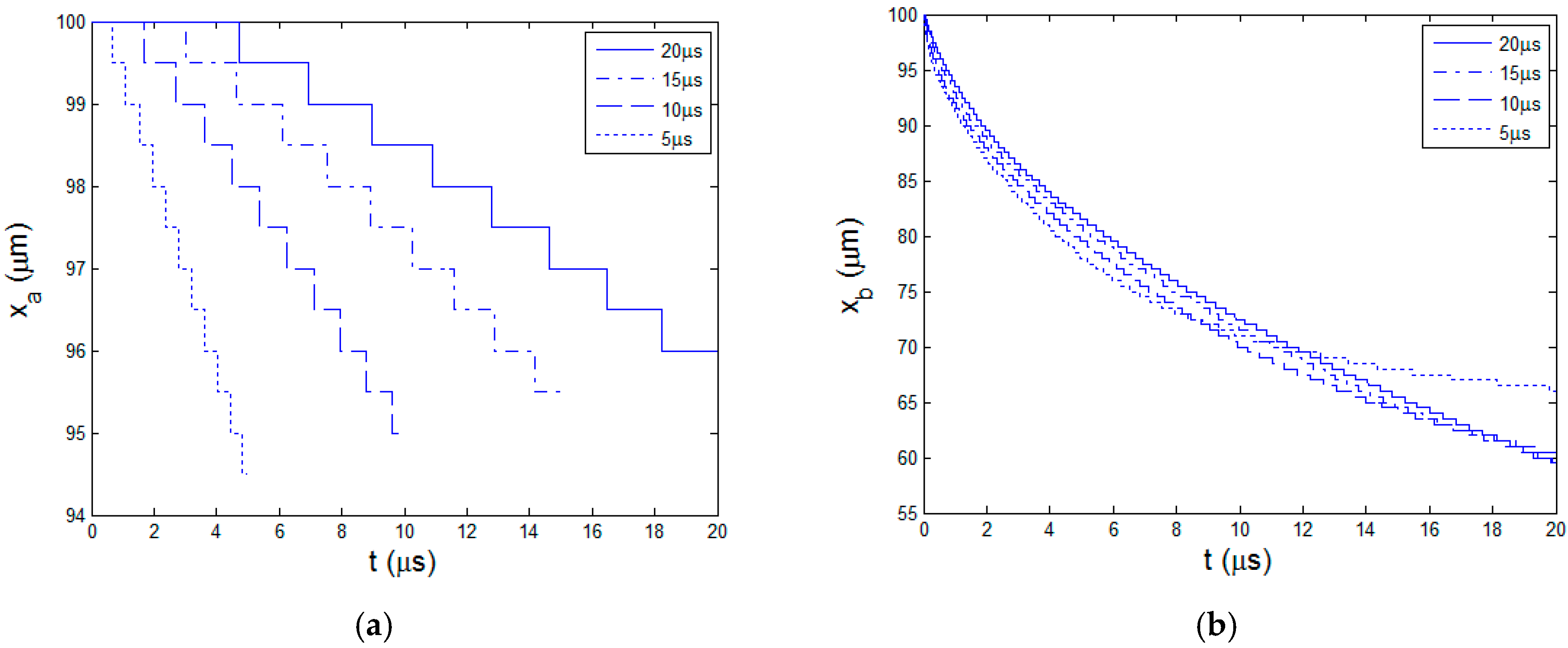
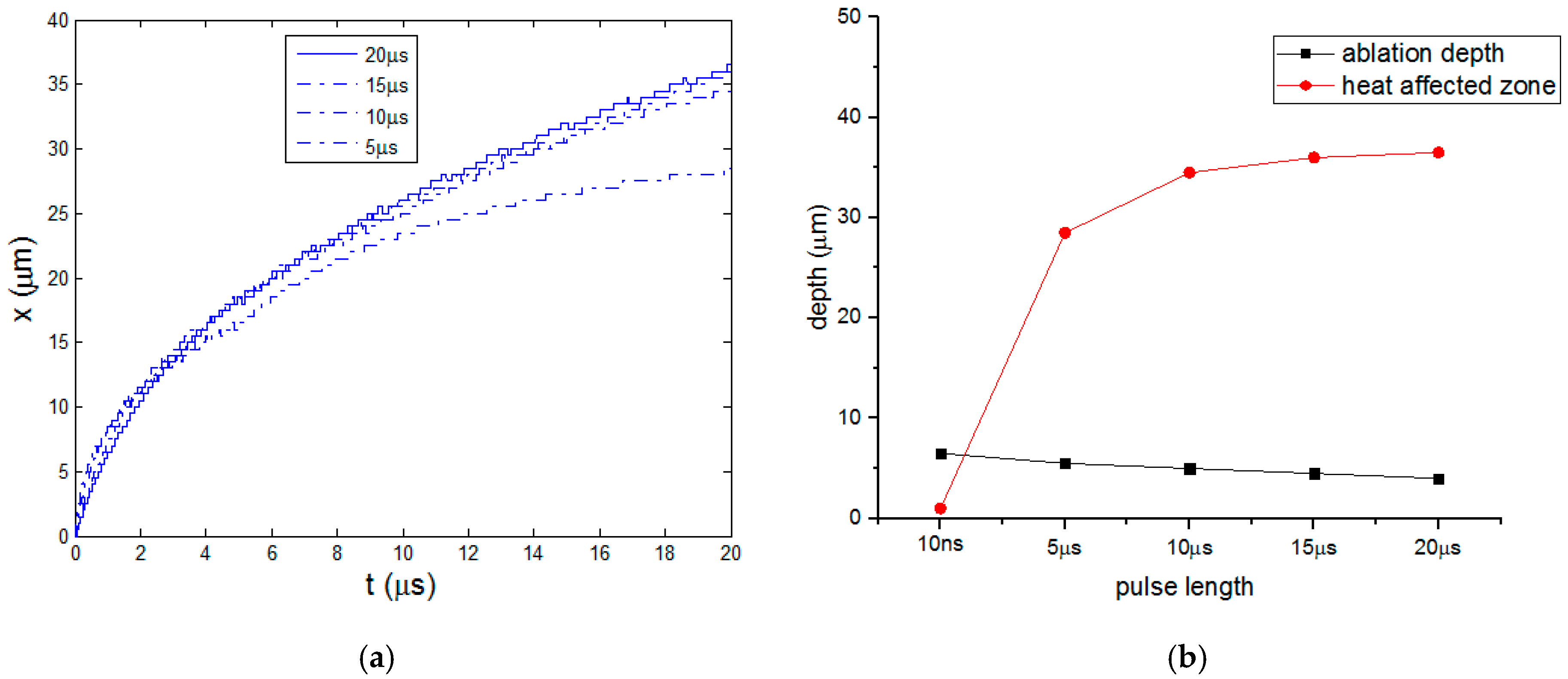
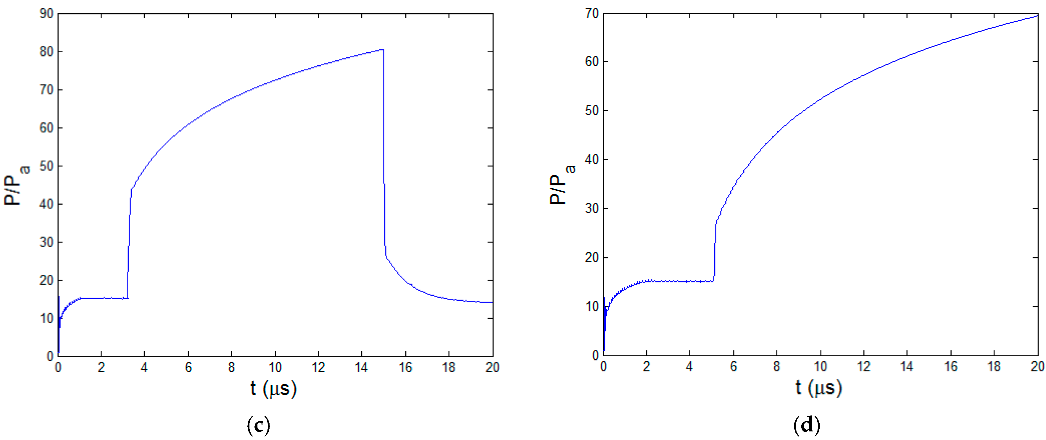
4.2. Effect of Laser Pulse Length
5. Conclusions
Acknowledgments
Author Contributions
Conflicts of Interest
References
- Cai, D.; Song, M. Recent advance in functionalized graphene/polymer nanocomposites. J. Mater. Chem. 2010, 20, 7906–7915. [Google Scholar] [CrossRef]
- Song, K.; Zhang, Y.; Meng, J.; Green, E.C.; Tajaddod, N.; Li, H.; Minus, M.L. Structural polymer-based carbon nanotube composite fibers: Understanding the processing–structure–performance relationship. Materials 2013, 6, 2543–2577. [Google Scholar] [CrossRef]
- Chung, D. Carbon Fiber Composites; Butterworth-Heinemann: Washington, MA, USA, 2012. [Google Scholar]
- Katnam, K.B.; Da Silva, L.F.M.; Young, T.M. Bonded repair of composite aircraft structures: A review of scientific challenges and opportunities. Prog. Aerosp. Sci. 2013, 61, 26–42. [Google Scholar] [CrossRef]
- Sheikh-Ahmad, J.Y. Machining of Polymer Composites; Springer: New York, NY, USA, 2009. [Google Scholar]
- Leone, C.; Papa, I.; Tagliaferri, F.; Lopresto, V. Investigation of CFRP laser milling using a 30 W Q-switched yb:YAG fiber laser: Effect of process parameters on removal mechanisms and HAZ formation. Compos. Part. A Appl. S. Manuf. 2013, 55, 129–142. [Google Scholar] [CrossRef]
- Romoli, L.; Fischer, F.; Kling, R. A study on UV laser drilling of PEEK reinforced with carbon fibers. Opt. Laser. Eng. 2012, 50, 449–457. [Google Scholar] [CrossRef]
- Hu, J.; Xu, H. Pocket milling of carbon fiber-reinforced plastics using 532-nm nanosecond pulsed laser: An experimental investigation. J. Compos. Mater. 2016, 50, 2861–2869. [Google Scholar] [CrossRef]
- Li, Z.L.; Zheng, H.Y.; Lim, G.C.; Chu, P.L.; Li, L. Study on UV laser machining quality of carbon fiber reinforced composites. Compos. Part. A Appl. S. Manuf. 2010, 41, 1403–1408. [Google Scholar] [CrossRef]
- Herzog, D.; Jaeschke, P.; Meier, O.; Haferkamp, H. Investigations on the thermal effect caused by laser cutting with respect to static strength of CFRP. Int. J. Mach. Tool. Manuf. 2008, 48, 1464–1473. [Google Scholar] [CrossRef]
- Lee, C.K.; Chaiken, R.F.; Singer, J.M. Charring pyrolysis of wood in fires by laser simulation. Symp. Int. Combust. 1977, 16, 1459–1470. [Google Scholar] [CrossRef]
- Farkas, E.; Meszena, Z.; Toldy, A.; Matkó, S.; Marosfői, B.; Marosi, G. Modelling of transport processes in a developing char. Polym. Degrade. Stab. 2008, 93, 1205–1213. [Google Scholar] [CrossRef]
- Staggs, J. Heat and mass transport in developing chars. Polym. Degrade. Stab. 2003, 82, 297–307. [Google Scholar] [CrossRef]
- Xu, H.; Hu, J.; Yu, Z. Absorption behavior analysis of carbon fiber reinforced polymer in laser processing. Opt. Mater. Express 2015, 5, 2330–2336. [Google Scholar] [CrossRef]
- Chippendale, R. Modelling of the Thermal Chemical Damage Caused to Carbon Fibre Composites. Ph.D. Thesis, University of Southampton, Southampton, UK, July 2013. [Google Scholar]
- Ogasawara, T.; Hirano, Y.; Yoshimura, A. Coupled thermal–electrical analysis for carbon fiber/epoxy composites exposed to simulated lightning current. Compos. Part. A Appl. S. Manuf. 2010, 41, 973–981. [Google Scholar] [CrossRef]
- Li, Z.L.; Chu, P.L.; Zheng, H.Y.; Lim, G.C.; Li, L.; Marimuthu, S.; Negarestani, R.; Sheikh, M.; Mativenga, P. Process development of laser machining of carbon fibre reinforced plastic composites. In Proceedings of the International Congress on Applications of Lasers and Elctro-Optics, Temecula, CA, USA, October 2008; pp. 222–231.


| Laser processing parameters | Values | Material properties [8] | Carbon fiber | Epoxy matrix |
|---|---|---|---|---|
| Laser power P (W) | 12 | Volume fraction φ | 0.6 | 0.4 |
| Repetition rate F (kHz) | 50 | Density ρ (kg/m3) | 1,850 | 1,200 |
| Initial temperature T0 (K) | 300 | Heat conductivity k (W/(m·K)) | 50 | 0.1 |
| Laser spot diameter (μm) | 25 | Heat capacity C (J/(kg3·K)) | 710 | 1,884 |
| Absorptivity A | 0.94 [14] | Latent heat L (kJ/kg) | 43,000 | 1,000 |
| Degradation temperature T1 (K) | 3,600 | 593 | ||
| Degradation temperature T2 (K) | 3,900 | 773 |
| Material properties | Values |
|---|---|
| Density ρg (Kg/m3) | 1.16 |
| Dynamic viscosity μ (Pa∙s) | 3 × 10⁻⁵ |
| Heat conductivity kg (W/m∙K) | 0.01 |
| Heat capacity C (J/Kg∙K) | 1,000 |
© 2016 by the authors. Licensee MDPI, Basel, Switzerland. This article is an open access article distributed under the terms and conditions of the Creative Commons Attribution (CC-BY) license ( http://creativecommons.org/licenses/by/4.0/).
Share and Cite
Xu, H.; Hu, J. Study of Polymer Matrix Degradation Behavior in CFRP Short Pulsed Laser Processing. Polymers 2016, 8, 299. https://doi.org/10.3390/polym8080299
Xu H, Hu J. Study of Polymer Matrix Degradation Behavior in CFRP Short Pulsed Laser Processing. Polymers. 2016; 8(8):299. https://doi.org/10.3390/polym8080299
Chicago/Turabian StyleXu, Hebing, and Jun Hu. 2016. "Study of Polymer Matrix Degradation Behavior in CFRP Short Pulsed Laser Processing" Polymers 8, no. 8: 299. https://doi.org/10.3390/polym8080299
APA StyleXu, H., & Hu, J. (2016). Study of Polymer Matrix Degradation Behavior in CFRP Short Pulsed Laser Processing. Polymers, 8(8), 299. https://doi.org/10.3390/polym8080299