Review

Solar Paint: From Synthesis to Printing

Centre for Organic Electronics, University of Newcastle, Callaghan, NSW 2308, Australia
*
Author to whom correspondence should be addressed.
Polymers 2014, 6(11), 2832-2844; https://doi.org/10.3390/polym6112832
Submission received: 12 September 2014 / Revised: 22 October 2014 / Accepted: 4 November 2014 / Published: 13 November 2014
(This article belongs to the Special Issue Organic Solar Cells)

Abstract

:
Water-based polymer nanoparticle dispersions (solar paint) offer the prospect of addressing two of the main challenges associated with printing large area organic photovoltaic devices; namely, how to control the nanoscale architecture of the active layer and eliminate the need for hazardous organic solvents during device fabrication. In this paper, we review progress in the field of nanoparticulate organic photovoltaic (NPOPV) devices and future prospects for large-scale manufacturing of solar cells based on this technology.

Graphical Abstract

1. Introduction

Organic photovoltaics (OPVs) offer enormous potential as inexpensive coatings capable of generating electricity directly from sunlight [1,2]. These polymer blend materials can be printed at high speeds across large areas using roll-to-roll processing techniques, creating the tantalising vision of coating every roof and other suitable building surface with low-cost photovoltaics [3].
Conventionally, OPV devices are fabricated from mixtures of donor and acceptor materials dissolved in organic solvents, which are deposited to produce an interpenetrating network [4]. Current fabrication methodologies rely on the thermodynamics of demixing to produce phase segregated regions with the required optimum size of 20–50 nm [5]. However, two key aspects of current OPV fabrication are not well-suited to building large-area PV modules using high-speed printing techniques. First, using current fabrication approaches to control phase segregation across large areas is problematic [6]. Second, current OPV technology typically uses chlorinated solvents (e.g., chloroform), which are under continual regulatory pressure due to their hazardous and toxic nature [7,8]. As such, the increasingly harsh technical requirement for using these solvents means that their implementation in high-speed printing lines will be highly problematic, if not economically impractical [9].
Indeed, the need for an alternative, environmentally-friendly process for OPV device fabrication has only recently been recognized in the OPV literature. However, early attempts have focused on replacing halogenated solvents with aromatic hydrocarbons, which are not necessarily less hazardous [10,11,12,13]. The work of Søndergaard et al. on water-soluble [6,6]-phenyl-C61-buteric acid methylester (PCBM) and poly(3-hexylethiophene) (P3HT) analogues presented water-processed device structures producing an overall device efficiency of 0.7% [14]. The earliest reports of semiconducting polymer nanoparticles (NPs) dispersed in water showed that conductive coatings could be prepared by mixing colloidal (10–100 nm diameter) conducting polymer in a latex base [15,16]. In 2002, work by Landfester et al. showed that conjugated semiconducting polymers could be deposited from aqueous dispersions prepared by the miniemulsion process [17]. In 2003, Kietzke et al. reported the first OPV devices based on nanoparticles (50–250 nm diameter) of poly(9,9-dioctylfluorene-co-benzothiadiazole (F8BT) and poly(9,9-dioctylfluorene-co-N,N'-bis(4-butylphenyl)-N,N'-diphenyl-1,4-phenylenediamine) (PFB) semi-conducting polymers. However, their power conversion efficiency (PCE) was extremely low (<0.004%) and substantially less than the corresponding bulk heterojunction (BHJ) blend devices (~0.2%) [18]. Subsequently, Snaith reported even lower efficiencies using an electroplating technique to deposit the nanoparticles as the active layer in OPV devices [19]. More recently, roll-to-roll processing of water-dispersed nanoparticulate polymer solar cells with efficiencies of up to 0.55% for certain low band gap materials has been demonstrated with the relatively poor device performance ascribed to shunting and non-optimum morphology [20,21,22].
The relatively low efficiencies reported for OPVs derived from nanoparticulate films spin coated from water are perhaps unsurprising. To disperse these colloidal particles in water, a surfactant is added to lower the interfacial energy and to provide colloidal stability [23]. Upon spin coating, these surfactant molecules might be expected to form an insulating barrier between neighbouring particles that would tend to disrupt charge transport within the photovoltaic device [24,25]. In addition, semi-conducting polymer particles are usually highly sensitive to oxygen and especially water contaminants, which tend to rapidly degrade OPV performance [26].

2. Synthesis of NPs via the Miniemulsion Process
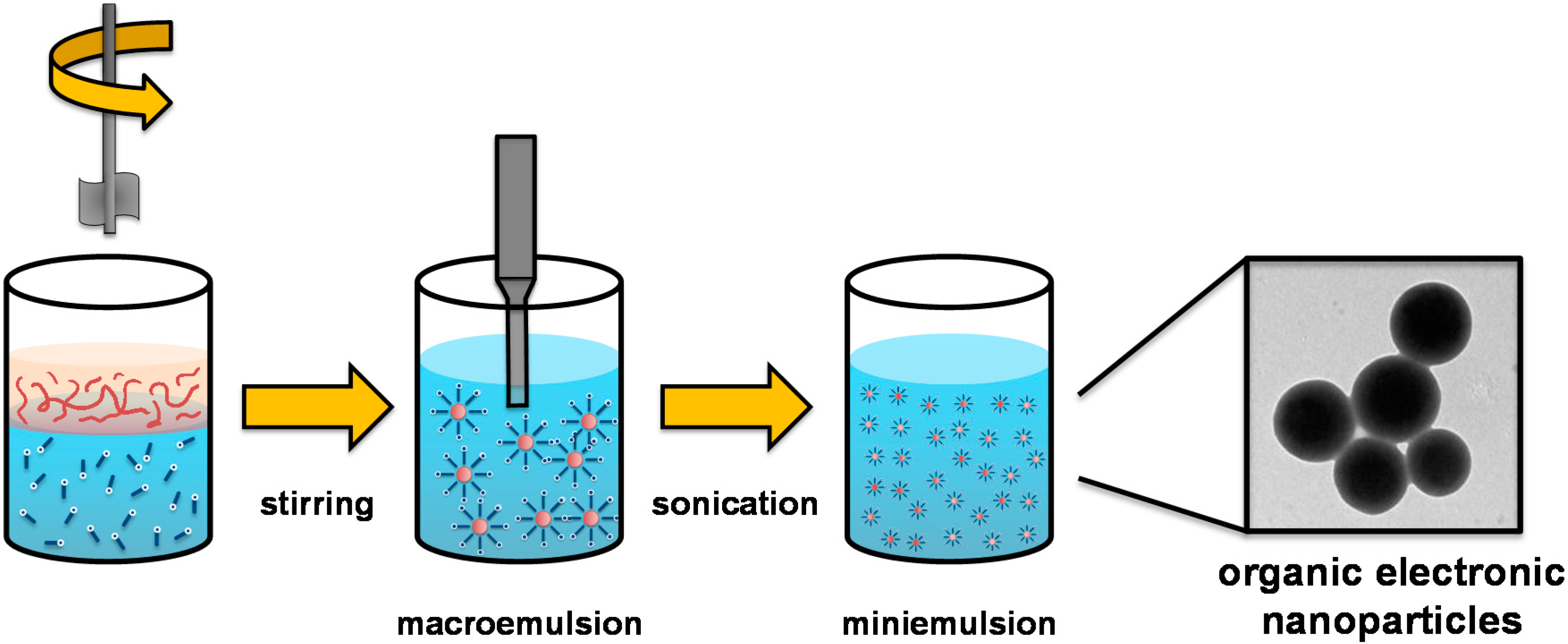
The nanoparticle fabrication method utilises ultrasound energy delivered via an ultrasound horn inserted into the reaction mixture to generate a miniemulsion (Figure 1). The ultrasound horn makes the formation of sub-micrometre droplets possible by applying high shear force. A liquid aqueous surfactant-containing phase (polar) is combined with an organic phase of polymer dissolved in chloroform (non-polar) to generate a macroemulsion, then ultrasonicated to form a miniemulsion. The polymer chloroform droplets constitute the dispersed phase with an aqueous continuous phase. This is a modification of the usual method for generating polymer nanoparticles where the dispersed phase was liquid monomer; this alternative method was first reported by Landfester and Kietzke [17,18]. Immediately after miniemulsification, the solvent is removed from the dispersed droplets via evaporation, leaving polymer nanoparticles. The final nanoparticle size can be varied by changing the initial concentration of surfactant in the aqueous phase.
Figure 1. Schematic of the NP synthesis process.
Polymers 06 02832 g001

3. Synthesis of NPs via Precipitation Methods

As an alternative to the miniemulsion approach, precipitation techniques offer a simple route to the production of semiconducting polymer nanoparticles via the injection of a solution of active material into a second solvent of poor solubility [27,28]. As such, the synthesis is quick, does not use surfactant, requires no heating (and therefore, no prefabrication annealing of the nanoparticles) in the nanoparticle synthesis phase and can readily be scaled up for the large-scale synthesis of material. In general, the dispersions have been shown to have lower stability and exhibit a compositional change upon standing due to preferential precipitation of particles of differing composition. However, the precipitation approach does offer the opportunity for inclusion of the nanoparticle synthesis as part of an active printing process, with particles being generated as and when required. Furthermore, Hirsch et al. have shown that by successive solvent displacement, it is possible to synthesise inverted core-shell particles where the structural arrangement is counter to the inherent surface energies of the materials [29].

4. The PFB:F8BT Nanoparticulate Organic Photovoltaic (NPOPV) Material System
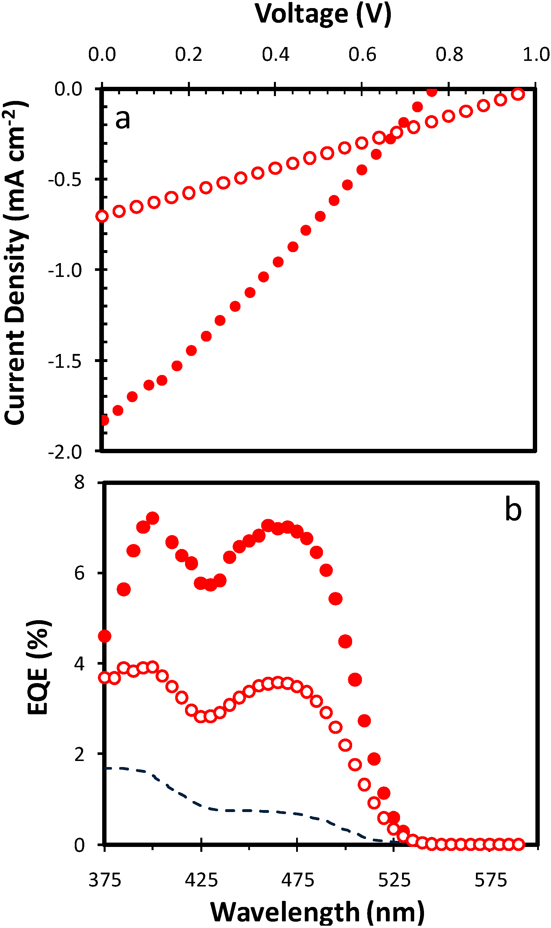
Early measurements of the power conversion efficiency of PFB:F8BT nanoparticle devices under solar illumination reported devices with a Jsc = 1 × 10⁻⁵ A cm−2 and VOC = 1.38 V [23], which (assuming a best estimate unannealed fill factor (FF) of 0.28 from bulk blend devices [24]) corresponds to a PCE of 0.004%. The only other photovoltaic measurements of PFB:F8BT nanoparticle devices were external quantum efficiency (EQE) plots reported by both Kietzke [18,23] and Snaith [19].
In 2012, Stapleton et al. reported multilayered photovoltaic devices fabricated from PFB:F8BT nanoparticles, which demonstrated the highest power conversion efficiencies observed for these polyfluorene nanoparticle materials [30]. This increased performance was achieved through the control of the surface energies of the individual components in the polymer nanoparticle and the post-deposition processing of the polymer nanoparticle layers. Significantly, this work showed that the fabricated nanoparticulate organic photovoltaic (NPOPV) devices were more efficient than the standard blend devices (Figure 2).
Figure 2. Comparison of the electrical characteristics of nanoparticle and bulk heterojunction devices. (a) Variation of current density vs. voltage for a five-layer PFB:F8BT (poly(9,9-dioctylfluorene-co-N,N'-bis(4-butylphenyl)-N,N'-diphenyl-1,4-phenylenediamine) (PFB); poly(9,9-dioctylfluorene-co-benzothiadiazole (F8BT)) nanoparticulate (filled circles) and a bulk heterojunction (open circles) device; (b) Variation of external quantum efficiency (EQE) vs. wavelength for a five-layer PFB:F8BT nanoparticulate (filled circles) and a bulk heterojunction (open circles) device. Also shown (dashed line) is the EQE plot for the nanoparticulate film device reported by Kietzke et al. [18]. Reproduced with permission from [30], published by Elsevier B.V., 2012.
Polymers 06 02832 g002
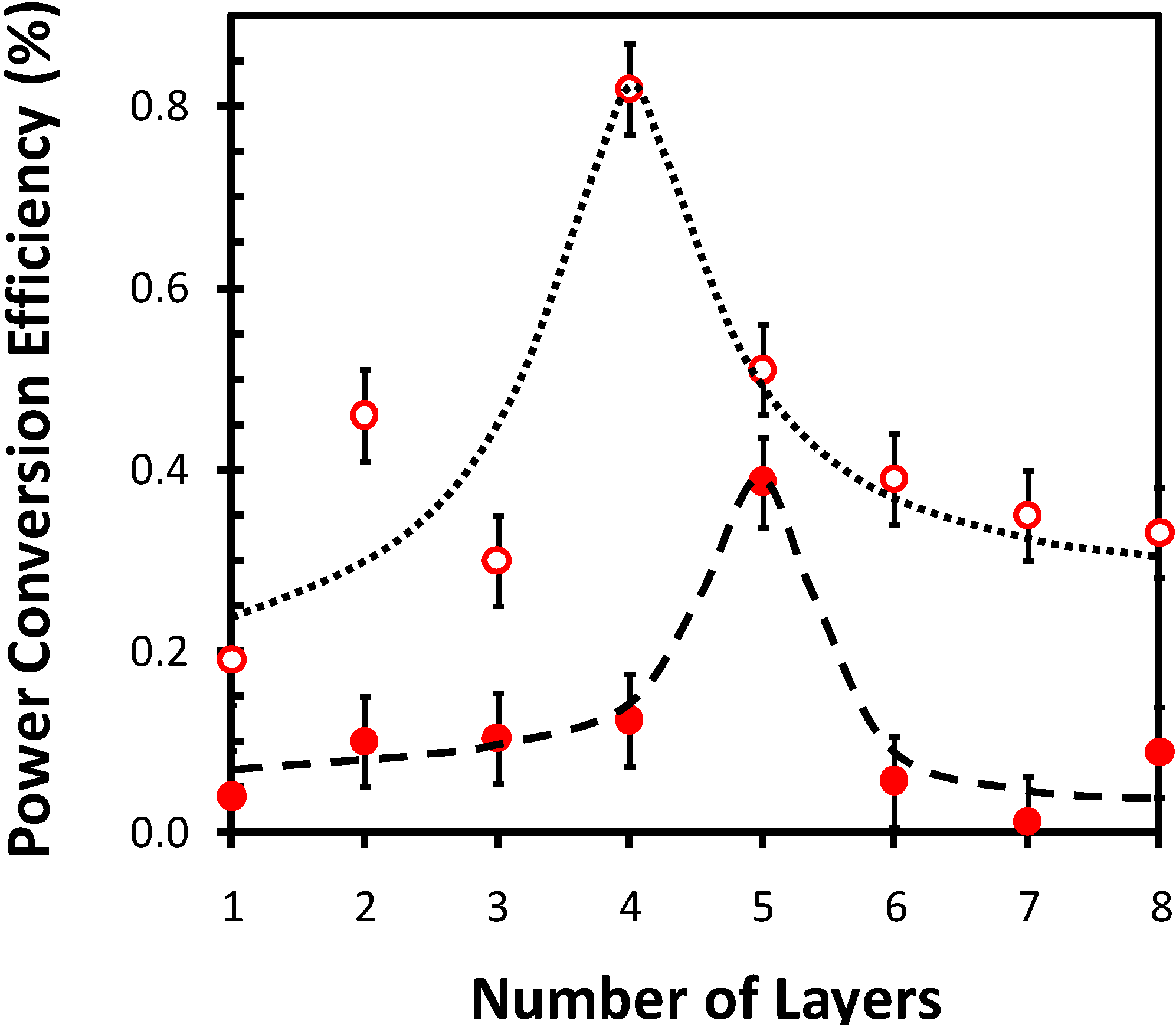
Subsequently, Vaughan et al. compared the effect of Ca and Al cathodes (two of the most common electrode materials) in OPV devices based on polyfluorene blend aqueous polymer nanoparticle (NP) dispersions [31]. They showed that PFB:F8BT NPOPV devices with Al and Ca/Al cathodes exhibit qualitatively very similar behaviour, with a peak PCE of ~0.4% for Al (consistent with Stapleton’s work [30]) and ~0.8% for Ca/Al, and that there is a distinct optimized thickness for the NP devices (Figure 3). The optimal thickness is a consequence of the competing physical effects of the repair and filling of defects for thin films [32,33] and the development of stress cracking in thick films [34]. Indeed, Stapleton’s work showed that the optimal layer thickness in these devices corresponds to the critical cracking thickness (CCT) above which stress cracking occurs, resulting in low shunt resistance and a reduction in device performance [30].
Figure 3. Variation of power conversion efficiency (PCE) with the number of deposited layers for PFB:F8BT nanoparticulate organic photovoltaic (NPOPV) devices fabricated with an Al cathode (filled circles) and a Ca/Al cathode (open circles). Dotted and dashed lines have been added to guide the eye. An average error has been determined based upon the variance for a minimum of ten devices for each number of layers. Reproduced with permission from [31], published by American Institute of Physics, 2012.
Polymers 06 02832 g003
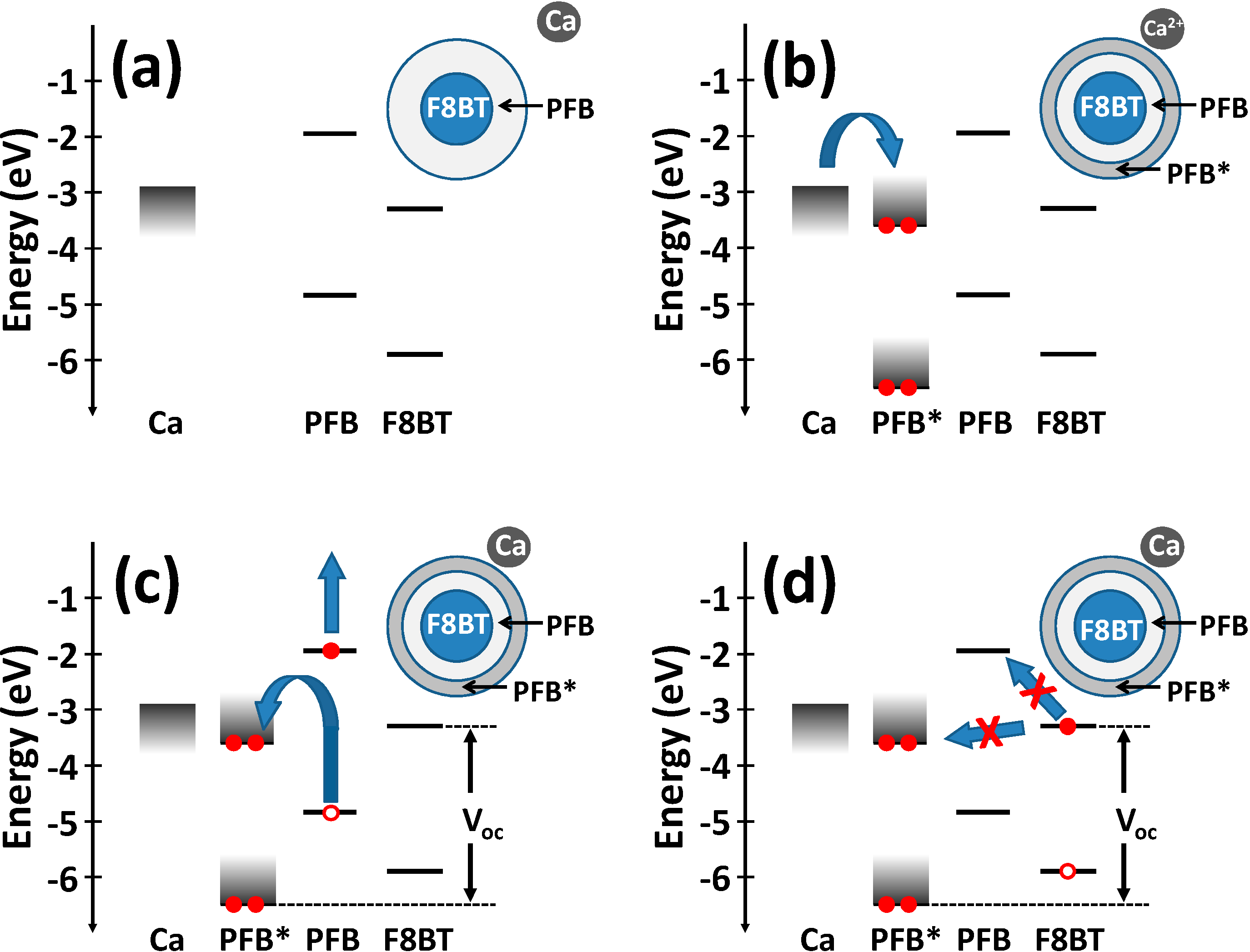
Overall, the work by Vaughan et al. provided further confirmation that the intrinsic morphology of NPOPV PFB:F8BT devices enhances the exciton dissociation relative to the corresponding BHJ structure. Moreover, the use of a Ca/Al cathode results in the creation of interfacial gap states (Figure 4), which reduce the recombination of charges generated by the PFB in these devices and restores open circuit voltage to the level obtained for an optimized BHJ device, resulting in a PCE approaching 1%.

5. The P3HT:PCBM NPOPV Material System
The first NPOPV devices based on the more common P3HT:PCBM system were reported by Lee et al., who synthesised P3HT:PCBM NPs using the miniemulsion method and then demonstrated their PV effect using conducting atomic force microscopy (AFM) under illumination [35]. At almost the same time, Larsen-Olsen et al. reported fully-printed reel-to-reel (R2R) devices using an inverted geometry also based on P3HT:PCBM NPs that exhibited a best PCE of only 0.3% [22].
Figure 4. Energy level diagrams for PFB:F8BT nanoparticles in the presence of calcium. (a) Calcium diffuses through the nanoparticle surface; (b) Calcium dopes the PFB-rich shell, producing gap states. Electron transfer occurs from calcium producing filled gap states; (c) An exciton generated on PFB approaches the doped PFB material (PFB*), and a hole transfers to the filled gap state, producing a more energetic electron; (d) Electron transfer from an exciton generated on F8BT to either the higher energy PFB lowest unoccupied molecular orbital (LUMO) or the filled lower energy PFB* LUMO is hindered. Reproduced with permission from [31], published by American Institute of Physics, 2012.
Polymers 06 02832 g004
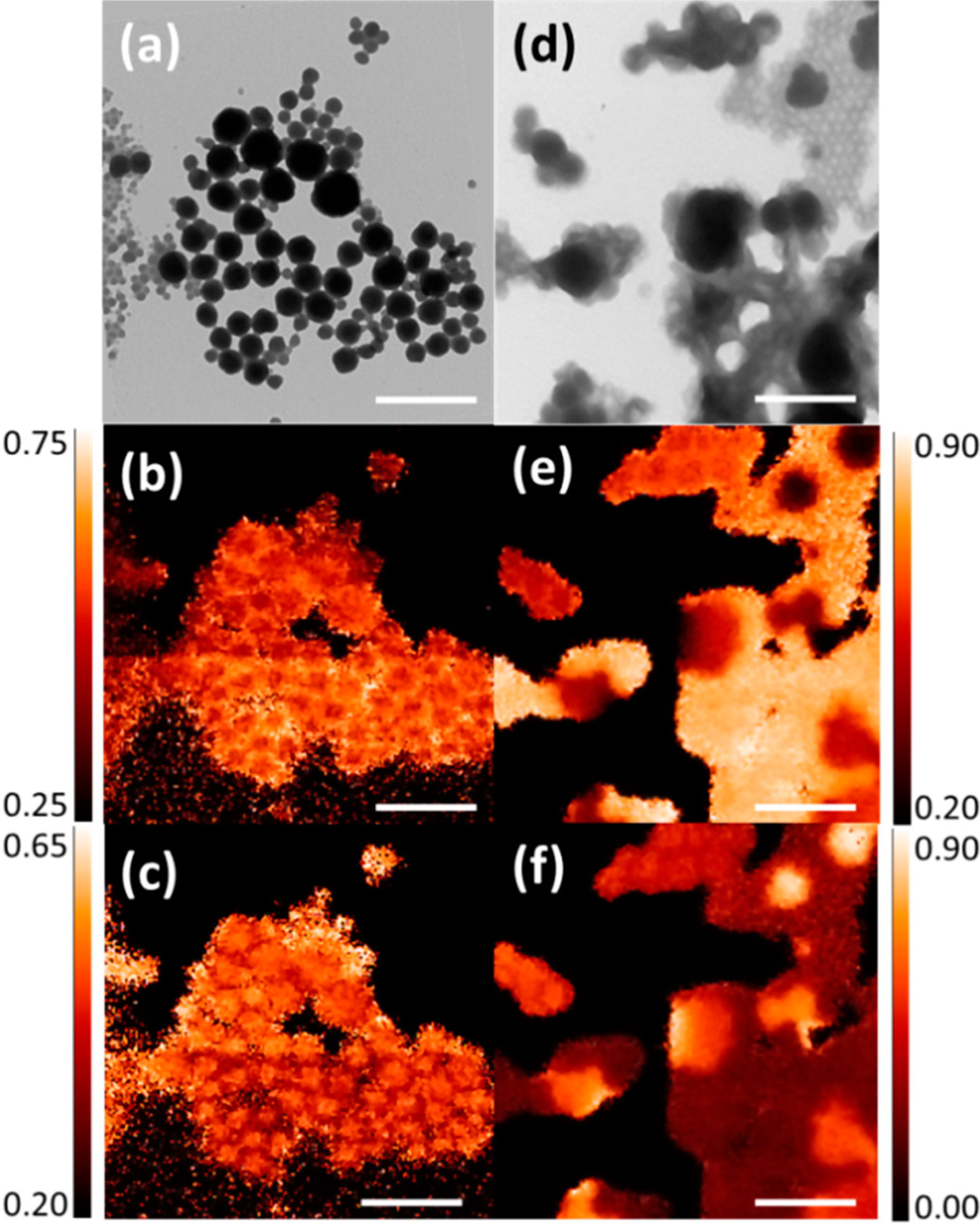
In a subsequent paper, Ulum et al. demonstrated NP-OPV devices fabricated from water-dispersed P3HT:PCBM nanoparticles that exhibited power conversion efficiencies (PCEs) of 1.30% and peak external quantum efficiencies (EQE) of 35% [36]. However, unlike the PFB:F8BT NPOPV system, the P3HT:PCBM NPOPV devices were less efficient than their bulk heterojunction counterparts. Scanning transmission X-ray microscopy (STXM) revealed that the active layer retains a highly structured NP morphology and comprises core-shell NPs consisting of a relatively pure PCBM core and a blended P3HT:PCBM shell (Figure 5). However, upon annealing, these NPOPV devices undergo extensive phase segregation and a corresponding decrease in device performance. Indeed, this work provided an explanation for the lower efficiency of the annealed P3HT:PCBM OPV devices, since thermal processing of the NP film results in an effectively “over-annealed” structure with gross phase segregation occurring, thus disrupting charge generation and transport.
Figure 5. (a) Transmission electron microscopy (TEM) image of the unannealed P3HT:PCBM NP film. Corresponding scanning transmission X-ray microscopy (STXM) maps of: (b) P3HT composition and (c) PCBM composition for the unannealed P3HT:PCBM NP film. (d) TEM image of the annealed P3HT:PCBM NP film. Corresponding STXM maps of: (e) P3HT composition and (f) PCBM composition for the annealed P3HT:PCBM NP film. The horizontal line in the composition images is produced by a small (<5%) beam intensity variation occurring in the P3HT mass plot. A 1-μm scale bar is shown. Reproduced with permission from [36], published by Elsevier B.V., 2013.
Polymers 06 02832 g005
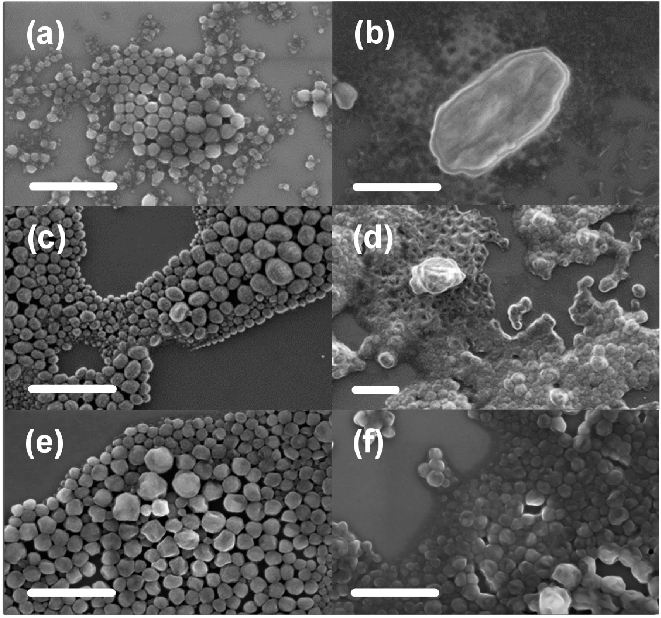
Holmes et al. reported both the intra- and inter-particle morphology of P3HT:PCBM nanoparticles before and after thermal annealing treatment, as a function of P3HT molecular weight [37]. The morphological changes resulting from thermal annealing were shown to be highly dependent upon the molecular weight of the polymer (Figure 6). Diffusion of PCBM in the polymer matrix was found to govern the morphology of annealed NP films, with the diffusion of molecular PCBM dominating for high molecular weight P3HT and the diffusion of larger PCBM cores being significant for low molecular weight P3HT. Using the Stokes–Einstein continuum model for diffusion, the authors were able to predict a threshold P3HT molecular weight of between 25 and 38 kg mol−1 for the PCBM core diffusion in P3HT:PCBM NP films, which was in good agreement with the experimental range of 16–44 kg mol−1. In a follow-up paper, Holmes et al. demonstrated that polymer molecular weight not only affects film morphology, but also the electronic and compositional structure of the nanoparticulate film. They showed that it is the domain composition that is most highly correlated with device performance and that this composition is driven by the PCBM mobility and aggregation within the nanoparticulate structure [38].
Figure 6. Scanning electron microscope (SEM) image of 9K P3HT:PCBM NPs unannealed (a) and annealed (b); 16K P3HT:PCBM NPs unannealed (c) and annealed (d); 72K P3HT:PCBM NPs unannealed (e) and annealed (f). All scale bars are 1 µm. Reproduced with permission from [37], published by Elsevier B.V., 2013.
Polymers 06 02832 g006
More recently, Richards et al. have used small-angle neutron scattering to determine the internal distribution of P3HT and PCBM inside the NPs as a function of the formulation while in dispersion. Their work shows that it is possible to generate a range of NP structures with quite small changes in formulation, and their work suggests that a uniform distribution of conjugated polymer and fullerene throughout the NP volume should deliver the best device performance [39]. The precipitation method has also been used to fabricate P3HT:PCBM NPOPVs, with Darwis et al. demonstrating comparable or improved power conversion efficiencies with respect to the corresponding surfactant-based NPOPV devices [40]. Interestingly, the precipitated NPs are initially fully blended and do not exhibit the core-shell morphology characteristic of the surfactant-containing P3HT:PCBM NPs.

6. The P3HT:ICBA NPOPV Material System
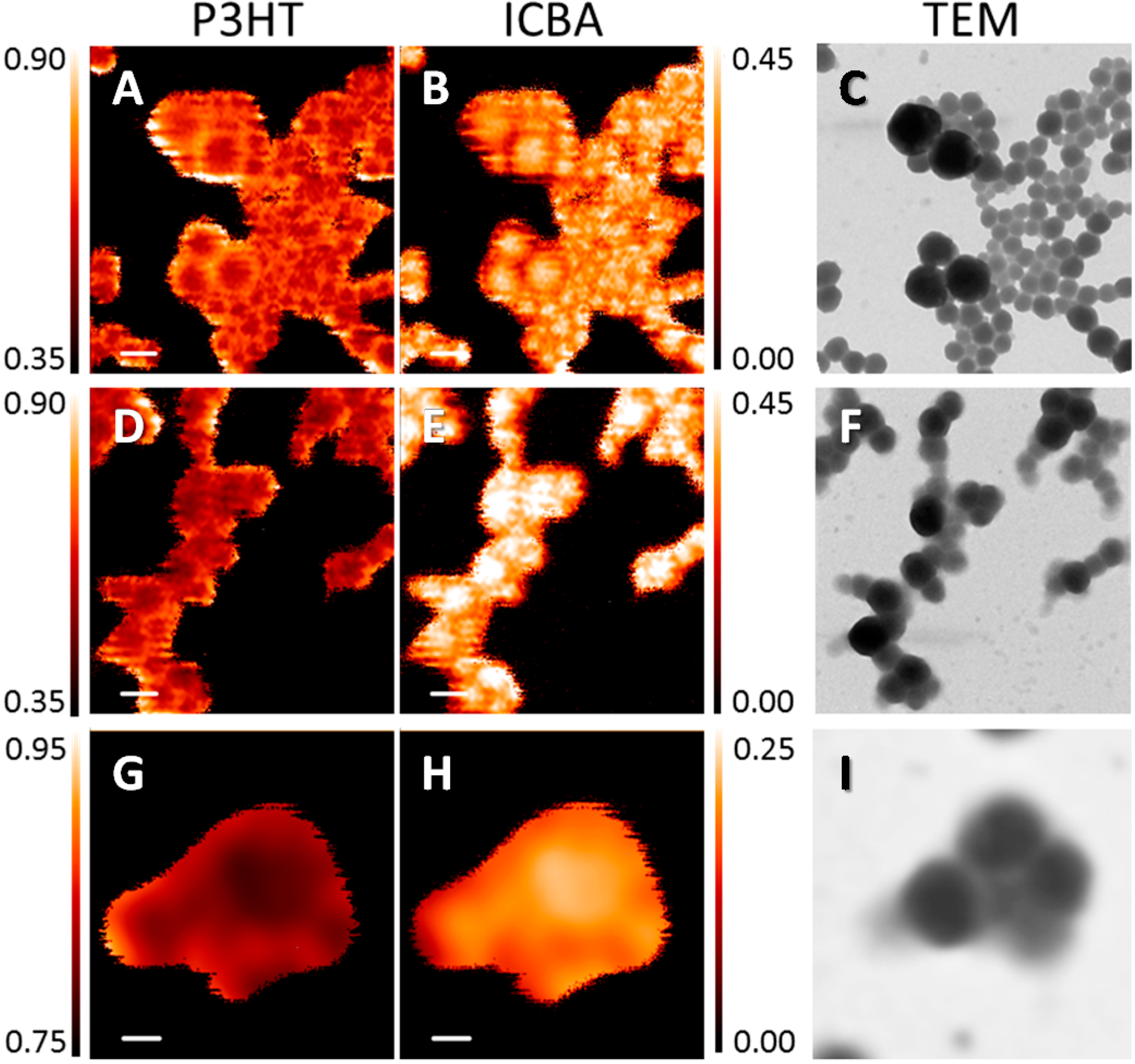
In 2013, Ulum et al. reported the performance of nanoparticulate organic photovoltaic (NPOPV) devices fabricated from poly(3-hexylthiophene) (P3HT):indene-C60-bisadduct (ICBA) blends. These devices exhibit power conversion efficiencies of 2.5%, which is the highest so far reported for NPOPV cells [41]. STXM mapping revealed that the unannealed NPs have a core shell structure with an enhanced ICBA concentration in the core region. Upon annealing, although the films maintained their NP structure, their core shell morphology was lost, and a mixed composition was observed (Figure 7).
Using the Flory–Huggins model, Ulum et al. showed that ICBA is miscible in P3HT at all weight fractions, which was supported by the STXM observations. Thus, the improved performance of the annealed P3HT:ICBA NPOPV devices is driven by the enhanced miscibility of ICBA in P3HT, which results in a more efficient intermixed structure.
Figure 7. The 2 μm × 2 μm P3HT and indene-C60-bisadduct (ICBA) STXM compositional maps for: as-spun (A,B), as-dried (D,E) NP films. The 1 μm × 1 μm P3HT and ICBA STXM compositional maps for an annealed (G,H) NP film. Corresponding TEM images for the as-spun (C), as-dried (F) and annealed (I) NP films are also shown. All scale bars are 1 μm. Reproduced with permission from [37], published by Elsevier B.V., 2013.
Polymers 06 02832 g007
Very recently, Gärtner et al. have demonstrated precipitated P3HT:ICBA NPOPVs with device efficiencies of 4% in an inverted device structure [42]. As is the case with previous work on OPV devices based on NPs synthesized using free precipitation [40], many depositions are required to form the continuous film needed for a working device. However, most encouragingly, this work does show that high efficiencies are possible using the NPOPV approach.

7. Summary of NPOPV Performance

A summary of the performance of NPOPV devices reported over the past few years is presented in Table 1. It is clear from the table that the performance of NPOPV devices has increased dramatically, with a rise of three orders of magnitude reported from 2003 to 2014.
Table 1. Summary of NPOPV device characteristics reported in the literature. The asterisked values are estimated based on a best estimate fill factor (FF) of 0.28 from bulk blend devices [30].
MaterialFabricationVoc (mV)Jsc (mA/cm2)FFPCE (%)Reference
PFB:F8BTminiemulsion1.380.010.28 *0.004 *[23]
PFB:F8BTminiemulsion7701.810.280.39[30]
PFB:F8BTminiemulsion1,5001.810.300.82[31]
P3HT:PCBMminiemulsion5175.450.471.31[36]
P3HT:PCBMprecipitation6344.840.361.09[40]
P3HT:ICBAminiemulsion7915.570.572.50[41]
P3HT:ICBAprecipitation7819.000.584.10[42]

8. Conclusions and Future Outlook

The recent development of water-based NPOPV coatings represents a paradigm shift in the development of low-cost OPV devices. This approach simultaneously provides control of morphology and eliminates the need for volatile flammable solvents in device production; two key challenges of current OPV device research. Indeed, the development of a water-based solar paint offers the tantalising prospect of printing large-area OPV devices using any existing printing facility. Moreover, it is increasingly recognised that the development of a water-based printable OPV system would be highly advantageous and that the current material systems based on chlorinated solvents are not suitable for commercial scale production.
The work described in this review shows that the new NPOPV methodology is generally applicable and that NPOPV device PCEs can be competitive with devices built from organic solvents. However, these studies also reveal that, from a materials point of view, NPs behave completely differently from polymer blends spun from organic solvents. Effectively, the NPs are a completely new material system, and as such, the old rules for OPV device fabrication that have been learnt for organic-based OPV devices no longer apply.
In the case of NPOPVs based on polyfluorene blends, the NP morphology results in a doubling of the device efficiency. However, for polymer:fullerene blends (e.g., P3HT:PCBM and P3HT:ICBA), morphology formation in the NP films is highly complex, and other factors (such as core diffusion) can dominate, resulting in unoptimised device structures and efficiencies.
The future outlook for these materials is extremely promising, with device efficiencies having increased from 0.004% to 4% in less than five years. The next stage of development will involve understanding the mechanisms that determine NP structure and NP film morphology and how these can be controlled and optimised. To date, the ability to control the morphology of OPV active layers on the nanoscale has yet to be realized. However, recent work demonstrates that the application of NP materials may allow this goal to be achieved.

Acknowledgments

Special thanks to at the University of Newcastle, Electron Microscopy and X-ray Unit. The University of Newcastle, the Directorate General of Higher Education Indonesia (DIKTI) and the Australian Renewable Energy Agency (ARENA) are gratefully acknowledged for PhD scholarships. We acknowledge financial support from the Commonwealth of Australia through the Access to Major Research Facilities Program. The Advanced Light Source (ALS) is supported by the Director, Office of Science, Office of Basic Energy Sciences, of the U.S. Department of Energy under Contract No. DE-AC02-05CH11231. This work was performed in part at the Materials node of the Australian National Fabrication Facility, which is a company established under the National Collaborative Research Infrastructure Strategy to provide nano- and micro-fabrication facilities for Australia’s researchers.

Author Contributions

Xiaojing Zhou, Warwick Belcher and Paul Dastoor conceived of designed and contributed to the experiments described in this review. Warwick Belcher and Paul Dastoor wrote the paper.

Conflicts of Interest

The authors declare no conflict of interest.

References

  1. Coakley, K.M.; McGehee, M.D. Conjugated polymer photovoltaic cells. Chem. Mater. 2004, 16, 4533–4542. [Google Scholar]
  2. Brabec, C.J.; Durrant, J.R. Solution-processed organic solar cells. MRS Bull. 2008, 33, 670–675. [Google Scholar]
  3. Dennler, G.; Brabec, C.J. Organic Photovoltaics: Materials, Device Physics and Manufacturing Technologies; Brabec, C.J., Dyakonov, V., Scherf, U., Eds.; Wiley-VCH: Weinheim, Germany, 2008; pp. 531–566. [Google Scholar]
  4. Günes, S.; Neugebauer, H.; Sariciftci, N.S. Conjugated polymer-based organic solar cells. Chem. Rev. 2007, 107, 1324–1338. [Google Scholar]
  5. Yang, X.; Loos, J. Toward high-performance polymer solar cells: The importance of morphology control. Macromolecules 2007, 40, 1353–1362. [Google Scholar]
  6. Krebs, F.C. Fabrication and processing of polymer solar cells: A review of printing and coating techniques. Sol. Energy Mater. Sol. Cells 2009, 93, 394–412. [Google Scholar]
  7. Ruder, A.M. Potential health effects of occupational chlorinated solvent exposure. Ann. N. Y. Acad. Sci. 2006, 1076, 207–227. [Google Scholar]
  8. Ward, E.M.; Schulte, P.A.; Straif, K.; Hopf, N.B.; Caldwell, J.C.; Carreón, T.; DeMarini, D.M.; Fowler, B.A.; Goldstein, B.D.; Hemminki, K.; et al. Research recommendations for selected IARC-classified agents. Environ. Health Perspect. 2010, 118, 1355–1362. [Google Scholar]
  9. Slunge, D.; Sterner, T. Implementation of policy instruments for chlorinated solvents. A comparison of design standards, bans, and taxes to phase out trichloroethylene. Eur. Environ. 2001, 11, 281–296. [Google Scholar]
  10. Burgués-Ceballos, I.; Machui, F.; Min, J.; Ameri, T.; Voigt, M.M.; Luponosov, Y.N.; Ponomarenko, S.A.; Lacharmoise, P.D.; Campoy-Quiles, M.; Brabec, C.J. Solubility based identification of green solvents for small molecule organic solar cells. Adv. Funct. Mater. 2014, 24, 1449–1457. [Google Scholar]
  11. Park, C.-D.; Fleetham, T.A.; Li, J.; Vogt, B.D. High performance bulk-heterojunction organic solar cells fabricated with non-halogenated solvent processing. Org. Electron. 2011, 12, 1465–1470. [Google Scholar]
  12. Lange, A.; Schindler, W.; Wegener, M.; Fostiropoulos, K.; Janietz, S. Inkjet printed solar cell active layers prepared from chlorine-free solvent systems. Sol. Energy Mater. Sol. Cells 2013, 109, 104–110. [Google Scholar]
  13. Chen, K.-S.; Yip, H.-L.; Schlenker, C.W.; Ginger, D.S.; Jen, A.K.-Y. Halogen-free solvent processing for sustainable development of high efficiency organic solar cells. Org. Electron. 2012, 12, 2870–2878. [Google Scholar]
  14. Søndergaard, R.; Helgesen, M.; Jørgensen, M.; Krebs, F.C. Fabrication of polymer solar cells using aqueous processing for all layers including the metal back electrode. Adv. Energy Mater. 2011, 1, 68–71. [Google Scholar]
  15. Eisazadeh, H.; Spinks, G.; Wallace, G.G. Electrochemical properties of conductive electroactive polymeric colloids. Mater. Forum 1992, 16, 341–344. [Google Scholar]
  16. Talaie, A.; Eisazadeh, H. Advanced conductive paints using smart colloidal polymeric composites: fabrication and computer classification. Iran. Polym. J. 1999, 8, 241–246. [Google Scholar]
  17. Landfester, K.; Montenegro, R.; Scherf, U.; Güntner, R.; Asawapirom, U.; Patil, S.; Neher, D.; Kietzke, T. Semiconducting polymer nanospheres in aqueous dispersion prepared by a miniemulsion process. Adv. Mater. 2002, 14, 651–655. [Google Scholar]
  18. Kietzke, T.; Neher, D.; Landfester, K.; Montenegro, M.; Güntner, R.; Scherf, U. Novel approaches to polymer blends based on polymer nanoparticles. Nat. Mater. 2003, 2, 408–412. [Google Scholar]
  19. Snaith, H.J.; Friend, R.H. Photovoltaic devices fabricated from an aqueous dispersion of polyfluorene nanoparticles using an electroplating method. Synth. Metals 2004, 147, 105–109. [Google Scholar]
  20. Andersen, T.R.; Larsen-Olsen, T.T.; Andreasen, B.; Böttiger, A.P.L.; Carlé, J.E.; Helgesen, M.; Bundgaard, E.; Norrman, K.; Andreasen, J.W.; Jørgensen, M.; et al. Aqueous processing of low-band-gap polymer solar cells using roll-to-roll methods. ACS Nano 2011, 5, 4188–4196. [Google Scholar]
  21. Larsen-Olsen, T.T.; Andersen, T.R.; Andreasen, B.; Böttiger, A.P.L.; Bundgaard, E.; Norrman, K.; Andreasen, J.W.; Jørgensen, M.; Krebs, F.C. Roll-to-roll processed polymer tandem solar cells partially processed from water. Sol. Energy Mater. Sol. Cells 2012, 97, 43–49. [Google Scholar]
  22. Larsen-Olsen, T.T.; Andreasen, B.; Andersen, T.R.; Böttiger, A.P.L.; Bundgaard, E.; Norrman, K.; Andreasen, J.W.; Jørgensen, M.; Krebs, F.C. Simultaneous multilayer formation of the polymer solar cell stack using roll-to-roll double slot-die coating from water. Sol. Energy Mater. Sol. Cells 2012, 97, 22–27. [Google Scholar]
  23. Kietzke, T.; Neher, D.; Kumke, M.; Montenegro, R.; Landfester, K.; Scherf, U. A nanoparticle approach to control the phase separation in polyfluorene photovoltaic devices. Macromolecules 2004, 37, 4882–4890. [Google Scholar]
  24. McNeill, C.R.; Westenhoff, S.; Groves, C.; Friend, R.H.; Greenham, N.C. Influence of nanoscale phase separation on the charge generation dynamics and photovoltaic performance of conjugated polymer blends: Balancing charge generation and separation. J. Phys. Chem. C 2007, 111, 19153–19160. [Google Scholar]
  25. Boulas, C.; Davidovits, J.V.; Rondelez, F.; Vuillaume, D. Suppression of charge carrier tunneling through organic self-assembled monolayers. Phys. Rev. Lett. 1996, 76, 4797–4800. [Google Scholar]
  26. Norrman, K.; Gevorgyan, S.A.; Krebs, F.C. Water-induced degradation of polymer solar cells studied by H218O labeling. ACS Appl. Mater. Interfaces 2009, 1, 102–112. [Google Scholar]
  27. Millstone, J.E.; Kavulak, D.F.J.; Woo, C.H.; Holcombe, T.W.; Westling, E.J.; Briseno, A.L.; Tomey, M.F.; Fréchet, J.M.J. Synthesis, properties, and electronic applications of size-controlled poly(3-hexylthiophene) nanoparticles. Langmuir 2010, 26, 13056–13061. [Google Scholar]
  28. Shimizu, H.; Yamada, M.; Wada, R.; Okabe, M. Preparation and characterization of water self-dispersible poly(3-hexylthiophene) particles. Polym. J. 2008, 40, 33–36. [Google Scholar]
  29. Chambon, S.; Schatz, C.; Sébire, V.; Pavageau, B.; Wantz, G.; Hirsch, L. Organic semiconductor core–shell nanoparticles designed through successive solvent displacements. Mater. Horiz. 2014, 1, 431–438. [Google Scholar]
  30. Stapleton, A.; Vaughan, B.; Xue, B.; Sesa, E.; Burke, K.; Zhou, X.; Bryant, G.; Werzer, O.; Nelson, A.; Kilcoyne, A.L.D.; et al. A multilayered approach to polyfluorene water-based organic photovoltaics. Sol. Energy Mater. Sol. Cells 2012, 102, 114–124. [Google Scholar]
  31. Vaughan, B.; Stapleton, A.; Xue, B.; Sesa, E.; Zhou, X.; Bryant, G.; Belcher, W.; Dastoor, P. Effect of a calcium cathode on water-based nanoparticulate solar cells. Appl. Phys. Lett. 2012, 101. [Google Scholar] [CrossRef]
  32. Steward, P.A.; Hearn, J.; Wilkinson, M.C. An overview of polymer latex film formation and properties. Adv. Colloid Interface Sci. 2000, 86, 195–267. [Google Scholar]
  33. Karpov, S.V.; Isaev, I.L.; Gavrilyuk, A.P.; Gerasimov, V.S.; Grachev, A.S. General principles of the crystallization of nanostructured disperse systems. Colloid 2009, 71, 314–329. [Google Scholar]
  34. Singh, K.; Tirumkudulu, M. Cracking in drying colloidal films. Phys. Rev. Lett. 2007, 98. [Google Scholar] [CrossRef]
  35. Lee, Y.-B.; Lee, S.H.; Kim, K.; Lee, J.W.; Han, K.-Y.; Kim, J.; Joo, J. Single nanoparticle of organic p-type and n-type hybrid materials: nanoscale phase separation and photovoltaic effect. J. Mater. Chem. 2012, 22, 2485–2490. [Google Scholar]
  36. Ulum, S.; Holmes, N.; Darwis, D.; Burke, K.; Kilcoyne, A.L.D.; Zhou, X.; Belcher, W.; Dastoor, P. Determining the structural motif of P3HT:PCBM nanoparticulate organic photovoltaic devices. Sol. Energy Mater. Sol. Cells 2013, 110, 43–48. [Google Scholar]
  37. Holmes, N.P.; Burke, K.B.; Sista, P.; Barr, M.; Stefan, M.C.; Kilcoyne, A.L.D.; Zhou, X.; Dastoor, P.C.; Belcher, W.J. Nano-domain behaviour in P3HT:PCBM nanoparticles, relating material properties to morphological changes. Sol. Energy Mater. Sol. Cells 2013, 117, 437–445. [Google Scholar]
  38. Holmes, N.P.; Ulum, S.; Sista, P.; Burke, K.B.; Wilson, M.G.; Stefan, M.C.; Zhou, X.; Dastoor, P.C.; Belcher, W.J. The effect of polymer molecular weight on P3HT:PCBM nanoparticulate organic photovoltaic device performance. Sol. Energy Mater. Sol. Cells 2014, 128, 369–377. [Google Scholar]
  39. Richards, J.J.; Whittle, C.L.; Shao, G.; Pozzo, L.D. Correlating structure and photocurrent for composite semiconducting nanoparticles with contrast variation small-angle neutron scattering and photoconductive atomic force microscopy. ACS Nano 2014, 8, 4313–4324. [Google Scholar]
  40. Darwis, D.; Holmes, N.; Elkington, D.; Kilcoyne, A.L.D.; Bryant, G.; Zhou, X.; Dastoor, P.; Belcher, W. Surfactant-free nanoparticulate organic photovoltaics. Sol. Energy Mater. Sol. Cells 2014, 121, 99–107. [Google Scholar]
  41. Ulum, S.; Holmes, N.; Barr, M.; Kilcoyne, A.L.D.; Gong, B.B.; Zhou, X.; Belcher, W.; Dastoor, P. The role of miscibility in polymer:fullerene nanoparticulate organic photovoltaic devices. Nano Energy 2013, 2, 897–905. [Google Scholar]
  42. Gärtner, S.; Christmann, M.; Sankaran, S.; Röhm, H.; Prinz, E.-M.; Penth, F.; Pütz, A.; Emre Türeli, A.; Penth, B.; Baumstümmler, B.; et al. Eco-friendly fabrication of 4% efficient organic solar cells from surfactant-free P3HT:ICBA nanoparticle dispersions. Adv. Mater. 2014, 26, 6653–6657. [Google Scholar]