
Fused Deposition Modeling of Polymer Composites: Development, Properties and Applications

 ,
,  ,
,  ,
,  and
and 
Abstract

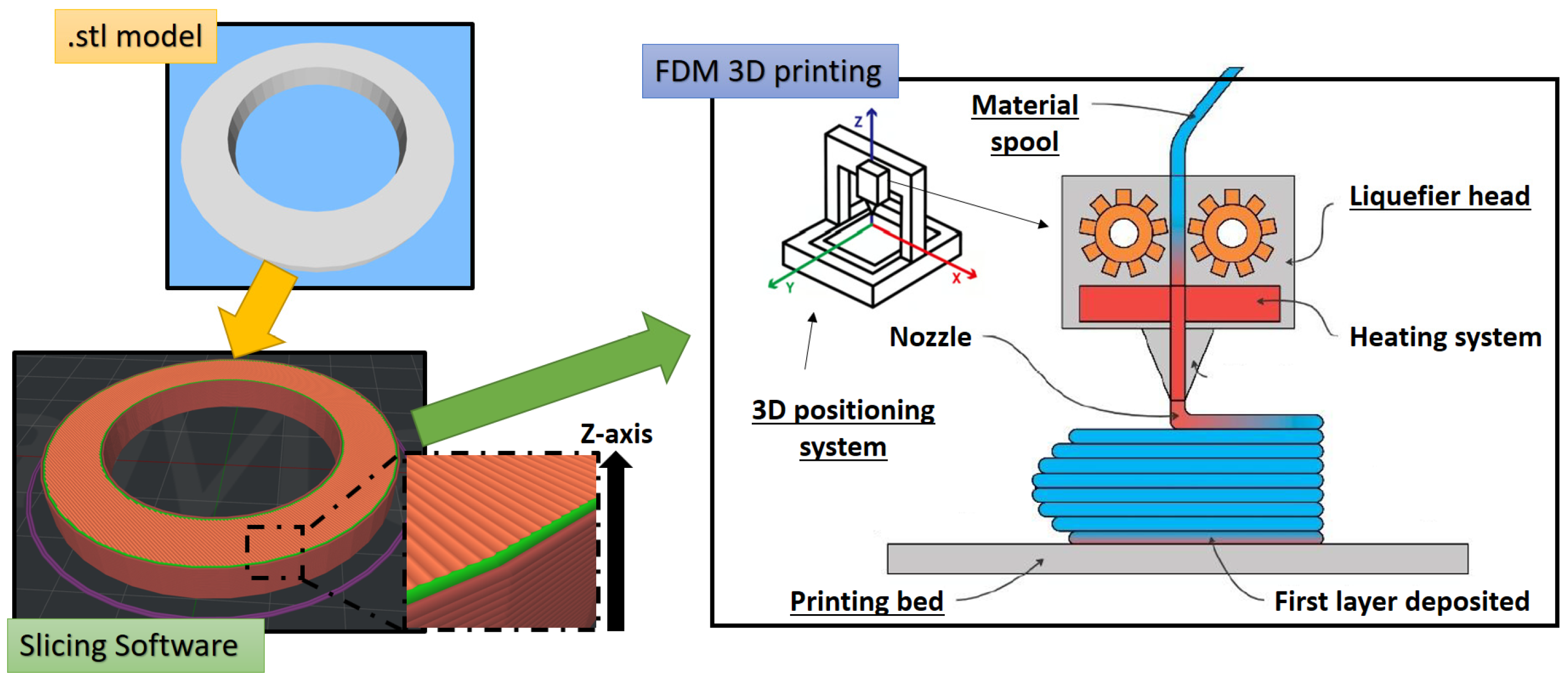
1. Introduction
- ability to print complex geometries;
- high printing speed without the need for post-production processes to refine the manufacts;
- no chemical changes in the raw material during the printing process, preserving the virgin material properties;
- limited maintenance required and safe system due to the simple construction principle;
- less material waste.
2. FDM Processes on Polymer and Polymer-Based Composites
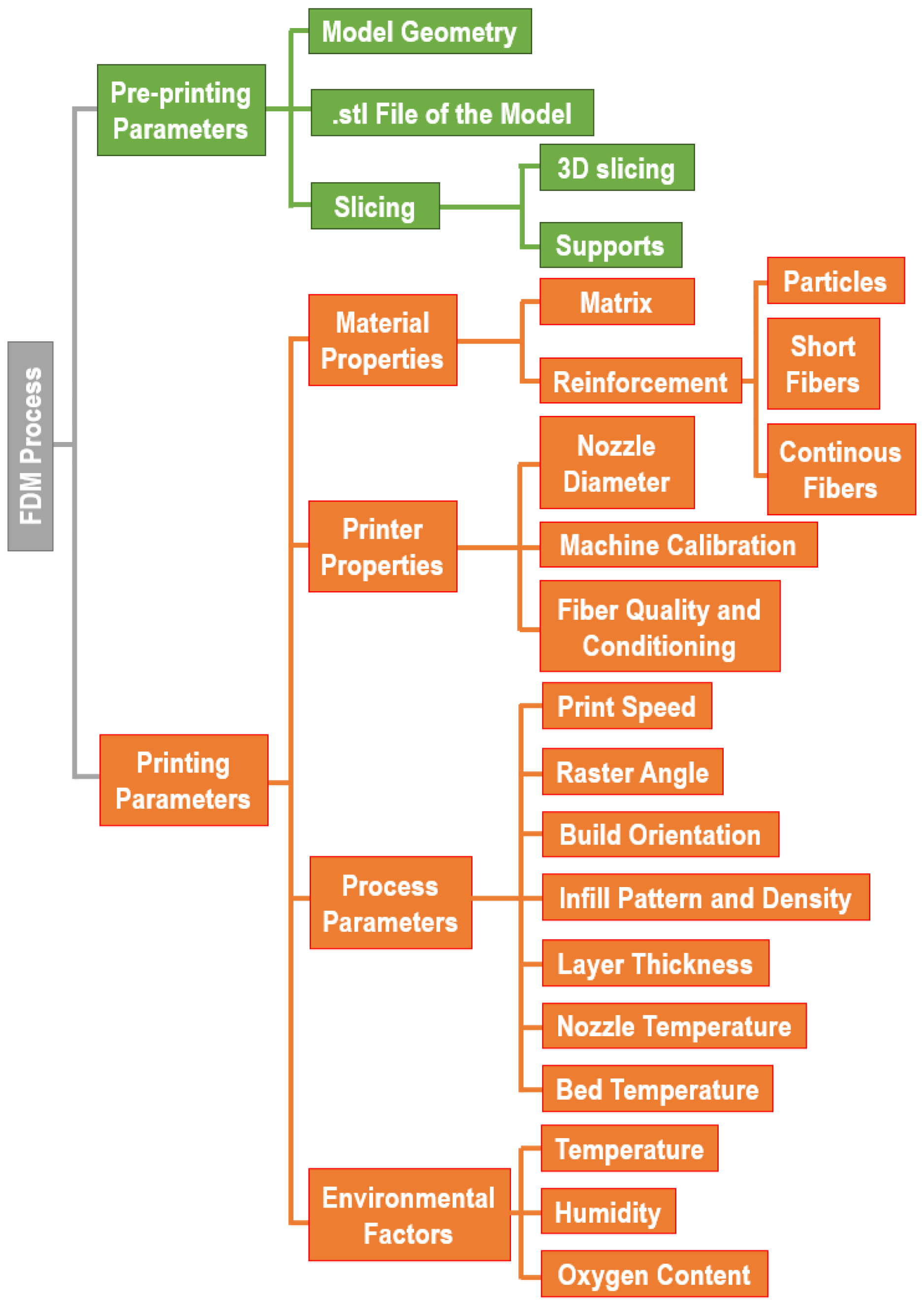
2.1. Parameters Affecting FDM Processes
2.1.1. Pre-Printing Parameters
2.1.2. Printing Parameters
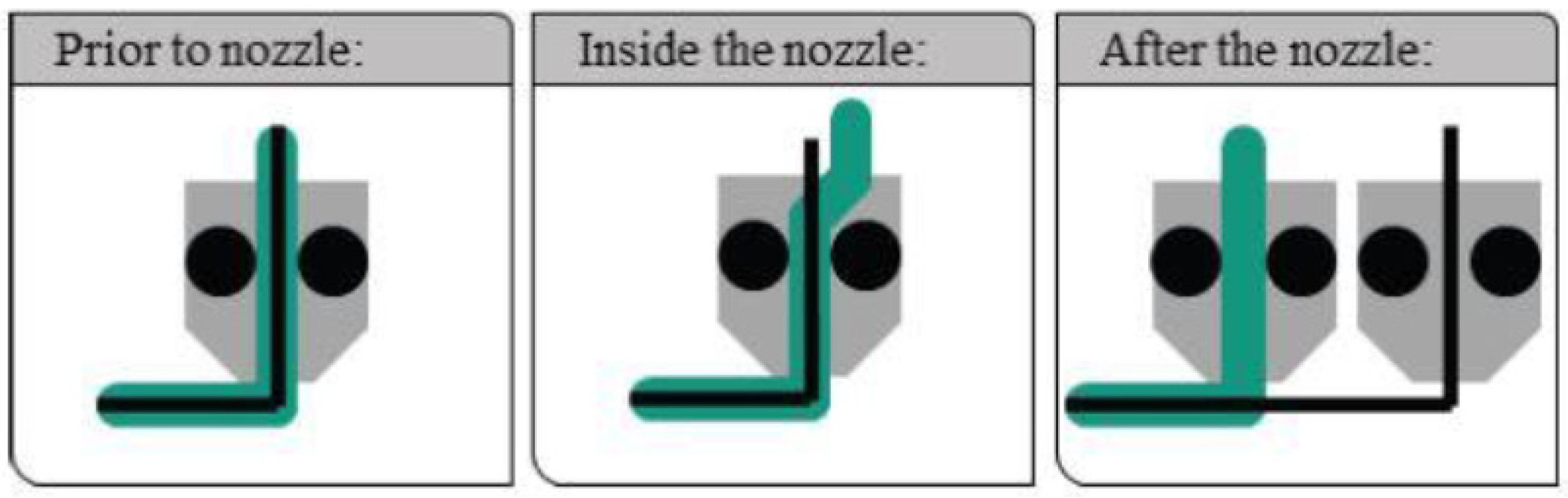
2.2. Composite FDM Filament Fabrication
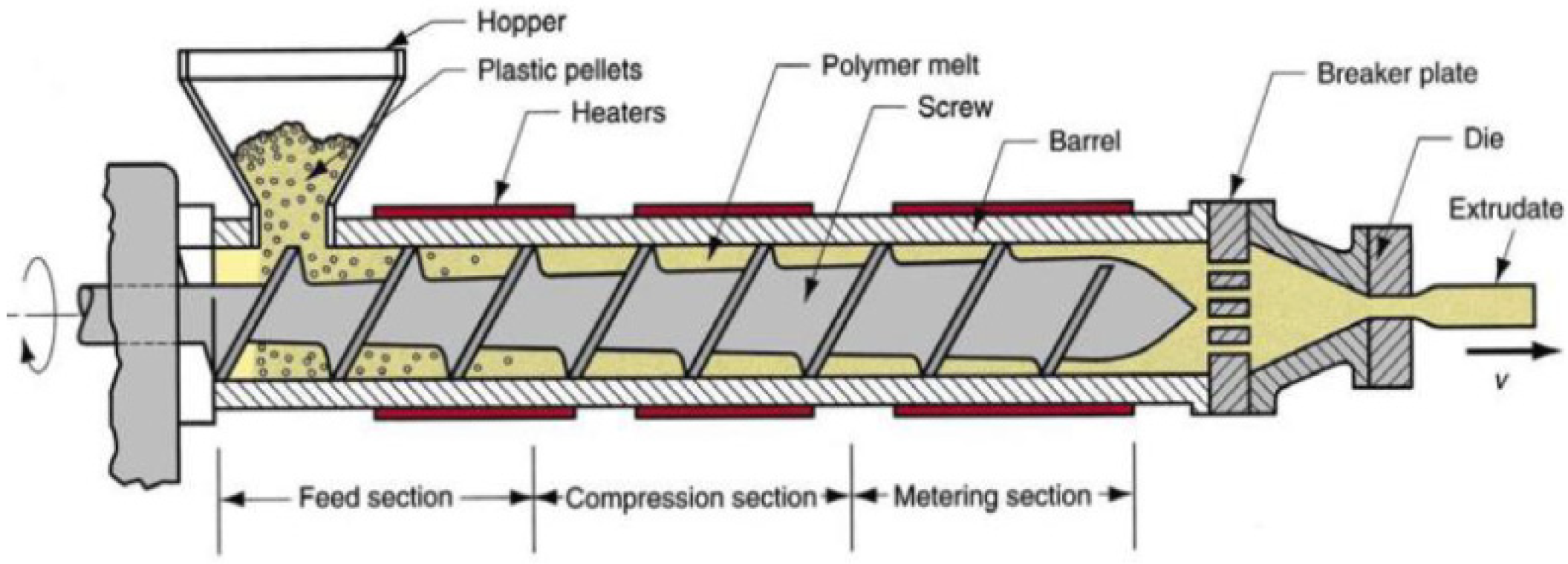
2.2.1. Composite Mixing and Pellets Fabrication
- Feeding zone: in this section, the feeding material, loaded through a hopper, falls by gravity into the heated barrel, contacting the rotating screw. The screw thread, in this zone, is high and constant.
- Compression zone: the screw thread reduces and the polymer, advancing along the screw, is forced into a smaller volume. The combination of compression and screw rotation generates friction and, consequently, heat, termed as shear heating. This heating source, along with the heat from the barrel heating system, induces the polymer melting. Moreover, the increase in the internal pressure facilitates the elimination of cavities and gases.
- Metering zone: here, the molted polymer is extruded through a nozzle to form the filament. Along this zone, the screw threat is constant throughout its length, analogously to the feeding zone.

| Extruder Type | Pros | Cons | Reference |
|---|---|---|---|
| SSE |
|
| [36,37,44] |
| TSE |
|
| [40,41,42,43] |
2.2.2. Filament Shaping and Spooling
3. Properties and Applications of FDM Polymer Composites
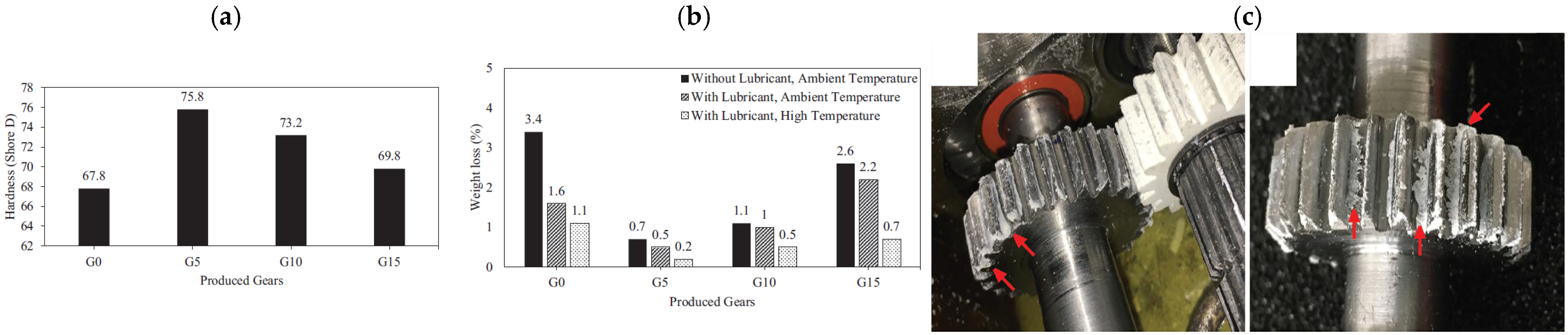
3.1. ABS-Based Composites
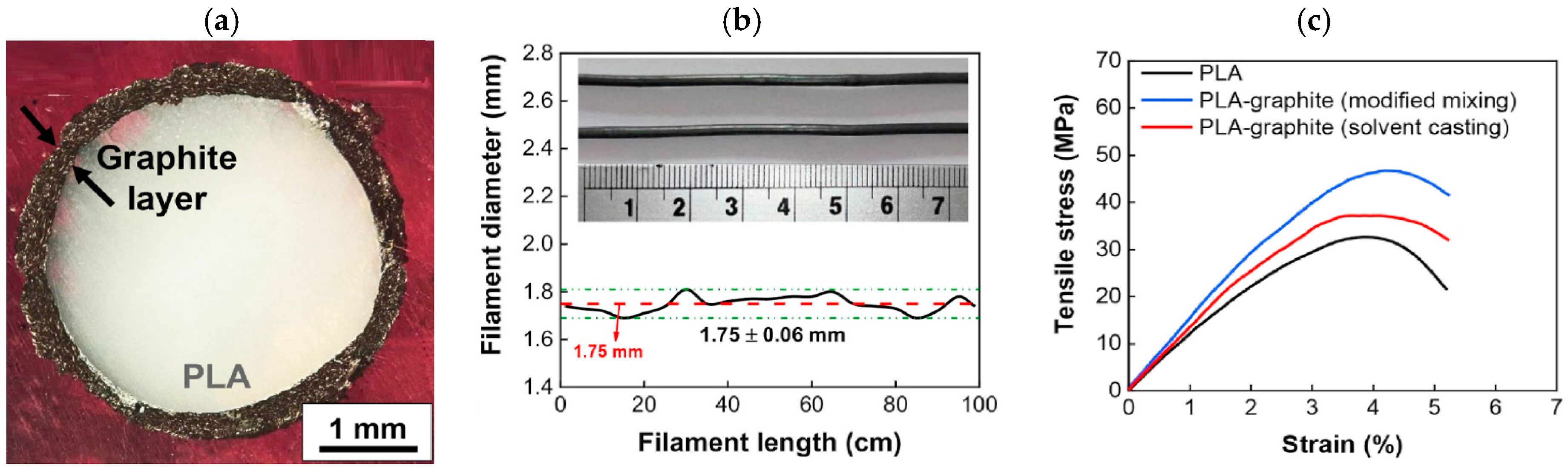
3.2. PLA-Based Composites
3.3. PEEK-Based Composites
- low density (1.32 g/cm3),
- good mechanical properties (tensile failure strain: 15%, good impact strength),
- preservation of mechanical properties up to 250 °C,
- excellent resistance to chemicals, solvents and hot water,
- biocompatibility.
| Matrix | Filler (Content) | ΔσT [%] (PD–PO) | ΔE [%] (PD–PO) | Δε [%] (PD–PO) | Δσf flex [%] (PD–PO) | ΔEflex [%] (PD–PO) | ρ3D [Ωcm] (PD–PO) | REF |
|---|---|---|---|---|---|---|---|---|
| PEEK | WS2 fullerene (1 wt%) | +33 (±45–F) | +11 (±45–F) | - | - | - | - | [90] |
| PEEK | HA (30 wt%) | +2.2 (±45–F) | +44 (±45–F) | −30 (±45–F) | −16% (±45–F) | +33 (±45–F) | - | [91] |
| PEEK | MWCNT/GNP (4/3 wt%) | +1.2 (±45–F) | +15 (±45–F) | −6.9 (±45–F) | - | - | 10−1 (±45–F) | [92] |
| PEEK | NdFeB (25 wt%) | −26 (±45–F) | −14 (±45–F) | −43 (±45–F) | - | - | - | [93] |
| PEEK | BC (10 wt%) | +27 (0/90–F) | +66 (0/90–F) | - | - | - | - | [94] |
| PEEK | GNP (3 wt%) | −0.15 (0–F) | +16.8 (0–F) | 11.6 (0–F) | - | - | - | [95] |
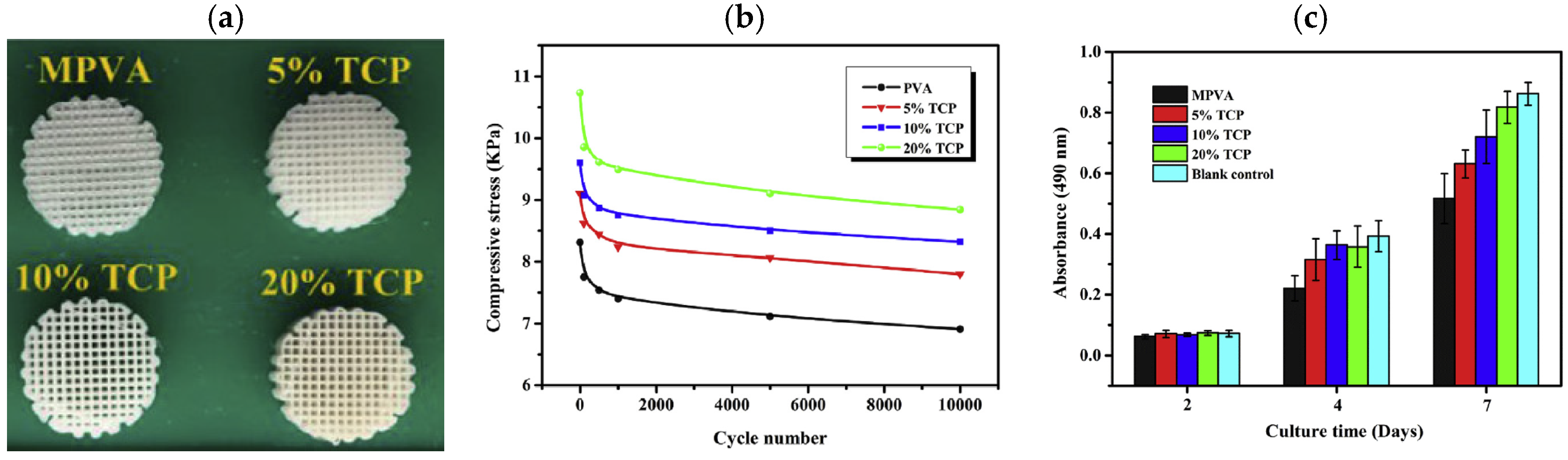
3.4. PVA-Based Composites

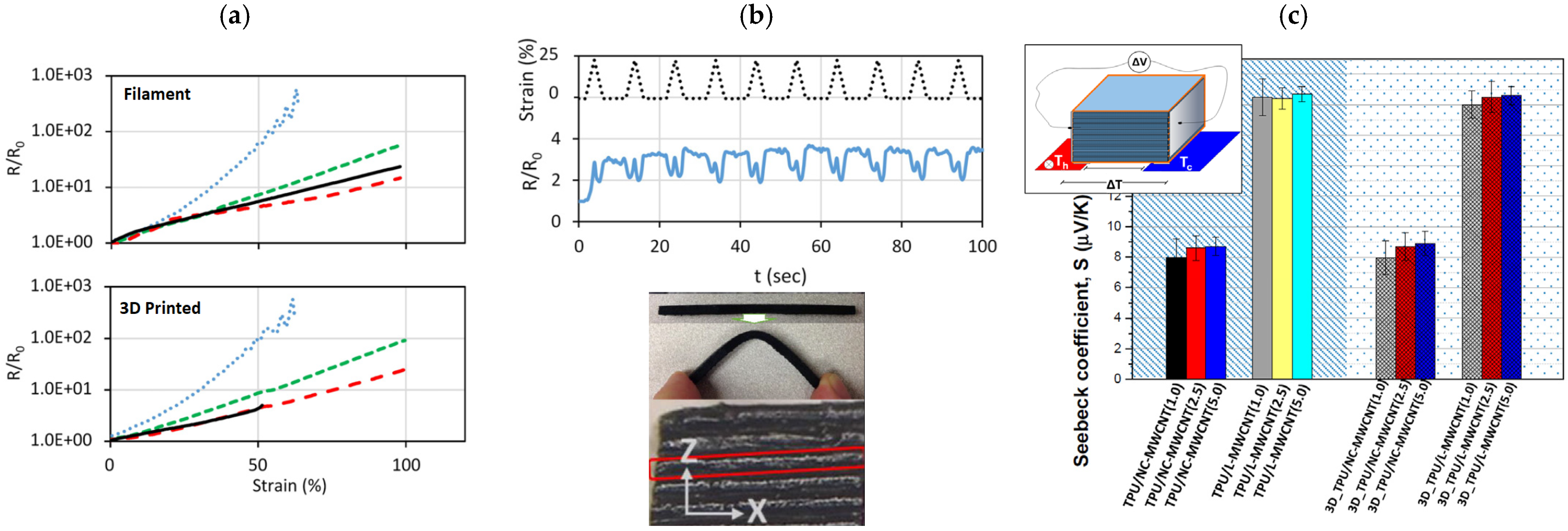
3.5. Thermoplastic Polyurethane (TPU)
- while MWCNT morphology slightly affects the mechanical and electrical properties of printed samples, the Seebeck coefficient is remarkably affected by the CNT typology (Figure 20c);
- the printing process does not influence the Seebeck coefficient, as the values are similar for filaments and 3D-printed samples (Figure 20c);
- the 3D-printed samples are isotropic in terms of the Seebeck coefficient.
3.6. Polyetherimide (PEI)
3.7. Polyamide (PA)
4. Properties and Applications of FDM Fiber-Reinforced Polymer Composites
5. Conclusions
Author Contributions
Funding
Acknowledgments
Conflicts of Interest
References
- Zhou, S.; Liu, G.; Wang, C.; Zhang, Y.; Yan, C.; Shi, Y. Thermal debinding for stereolithography additive manufacturing of advanced ceramic parts: A comprehensive review. Mater. Des. 2024, 238, 112632. [Google Scholar] [CrossRef]
- Shanmugam, V.; Pavan, M.V.; Babu, K.; Karnan, B. Fused deposition modeling based polymeric materials and their performance: A review. Polym. Compos. 2021, 42, 5656–5677. [Google Scholar] [CrossRef]
- Masood, S.H.; Song, W.Q. Development of new metal/polymer materials for rapid tooling using Fused deposition modelling. Mater. Des. 2004, 25, 587–594. [Google Scholar] [CrossRef]
- Jandyal, A.; Chaturvedi, I.; Wazir, I.; Raina, A.; Haq, M.I.U. 3D printing—A review of processes, materials and applications in industry 4.0. Sustain. Oper. Comput. 2022, 3, 33–42. [Google Scholar] [CrossRef]
- Kristiawan, R.B.; Imaduddin, F.; Ariawan, D.; Ubaidillah; Arifin, Z. A review on the fused deposition modeling (FDM) 3D printing: Filament processing, materials, and printing parameters. Open Eng. 2021, 11, 639–649. [Google Scholar] [CrossRef]
- Fico, D.; Rizzo, D.; Casciaro, R.; Corcione, C.E. A Review of Polymer-Based Materials for Fused Filament Fabrication (FFF): Focus on Sustainability and Recycled Materials. Polymers 2022, 14, 465. [Google Scholar] [CrossRef]
- Karimi, A.; Rahmatabadi, D.; Baghani, M. Various FDM Mechanisms Used in the Fabrication of Continuous-Fiber Reinforced Composites: A Review. Polymers 2024, 16, 831. [Google Scholar] [CrossRef]
- Rahim, T.N.A.T.; Abdullah, A.M.; Akil, H.M. Recent Developments in Fused Deposition Modeling-Based 3D Printing of Polymers and Their Composites. Polym. Rev. 2019, 59, 589–624. [Google Scholar] [CrossRef]
- Wickramasinghe, S.; Do, T.; Tran, P. FDM-Based 3D Printing of Polymer and Associated Composite: A Review on Mechanical Properties, Defects and Treatments. Polymers 2020, 12, 1529. [Google Scholar] [CrossRef]
- Luo, X.; Cheng, H.; Wu, X. Nanomaterials Reinforced Polymer Filament for Fused Deposition Modeling: A State-of-the-Art Review. Polymers 2023, 15, 2980. [Google Scholar] [CrossRef]
- Paz, R.; Moriche, R.; Monzón, M.; García, J. Influence of Manufacturing Parameters and Post Processing on the Electrical Conductivity of Extrusion-Based 3D Printed Nanocomposite Parts. Polymers 2020, 12, 733. [Google Scholar] [CrossRef] [PubMed]
- Penumakala, P.K.; Santo, J.; Thomas, A. A critical review on the fused deposition modeling of thermoplastic polymer composites. Compos. Part B Eng. 2020, 201, 108336. [Google Scholar] [CrossRef]
- Prüß, H.; Vietor, T. Design for Fiber-Reinforced Additive Manufacturing. J. Mech. Des. 2015, 137, 111409. [Google Scholar] [CrossRef]
- Mori, K.; Maeno, T.; Nakagawa, Y. Dieless forming of carbon fibre reinforced plastic parts using 3d printer. Procedia Eng. 2014, 81, 1595–1600. [Google Scholar] [CrossRef]
- Kabir, S.M.F.; Mathur, K.; Seyam, A.-F.M. A critical review on 3D printed continuous fiber-reinforced composites: History, mechanism, materials and properties. Compos. Struct. 2020, 232, 111476. [Google Scholar] [CrossRef]
- Zhang, H.; Zhang, L.; Zhang, H.; Wu, J.; An, X.; Yang, D. Fibre bridging and nozzle clogging in 3D printing of discontinuous carbon fibre-reinforced polymer composites: Coupled CFD-DEM modelling. Int. J. Adv. Manuf. Technol. 2021, 117, 3549–3562. [Google Scholar] [CrossRef]
- Banjanin, B.; Vladić, G.; Pál, M.; Dimovski, V.; Adamović, S.; Bošnjaković, G. Production factors influencing mechanical and physical properties of fdm printed embossing dies. In Proceedings of 9th International Symposium on Graphic Engineering and Design; Faculty of Technical Sciences: Novi Sad, Serbia, 2018; pp. 225–236. [Google Scholar]
- Iancu, C. About 3D printing file formats. Ann. Univ. Targu Jiu Eng. Ser. 2018, 2, 135–138. [Google Scholar]
- Roschli, A.; Borish, M.; Barnes, A.; MacDonald, E.; Wang, P.; Feldhausen, T. Support, raft, brim, and skirt pathing in Motion and Path Planning for Additive Manufacturing. Motion Path Plan. Addit. Manuf. 2023, 123–135. [Google Scholar]
- Solomon, I.J.; Sevvel, P.; Gunasekaran, J. A review on the various processing parameters in FDM. Mater. Today Proc. 2021, 37, 509–514. [Google Scholar] [CrossRef]
- Doshi, M.; Mahale, A.; Singh, S.K.; Deshmukh, S. Printing parameters and materials affecting mechanical properties of FDM-3D printed Parts: Perspective and prospects. Mater. Today Proc. 2022, 50, 2269–2275. [Google Scholar] [CrossRef]
- Dudek, P. FDM 3D Printing Technology in Manufacturing Composite Elements. Arch. Met. Mater. 2013, 58, 1415–1418. [Google Scholar] [CrossRef]
- Cardona, C.; Curdes, A.H.; Isaacs, A.J. Effects of Filament Diameter Tolerances in Fused Filament Fabrication. IU J. Undergrad. Res. 2016, 2, 44–47. [Google Scholar] [CrossRef]
- Rivera-López, F.; Pavón, M.M.L.; Correa, E.C.; Molina, M.H. Effects of Nozzle Temperature on Mechanical Properties of Polylactic Acid Specimens Fabricated by Fused Deposition Modeling. Polymers 2024, 16, 1867. [Google Scholar] [CrossRef]
- Farashi, S.; Vafaee, F. Effect of extruder temperature and printing speed on the tensile strength of fused deposition modeling (FDM) 3D printed samples: A meta-analysis study. Int. J. Interact. Des. Manuf. 2022, 16, 305–316. [Google Scholar] [CrossRef]
- Kuznetsov, V.E.; Solonin, A.N.; Urzhumtsev, O.D.; Schilling, R.; Tavitov, A.G. Strength of PLA Components Fabricated with Fused Deposition Technology Using a Desktop 3D Printer as a Function of Geometrical Parameters of the Process. Polymers 2018, 10, 313. [Google Scholar] [CrossRef]
- Christiyan, K.G.J.; Chandrasekhar, U.; Venkateswarlu, K. Flexural Properties of PLA Components Under Various Test Condition Manufactured by 3D Printer. J. Inst. Eng. Ser. C 2018, 99, 363–367. [Google Scholar] [CrossRef]
- Ning, F.; Cong, W.; Qiu, J.; Wei, J.; Wang, S. Additive Manufacturing of Carbon Fiber Reinforced Thermoplastic Composites Using Fused Deposition Modeling. Compos. Part B Eng. 2015, 80, 369–378. [Google Scholar] [CrossRef]
- Çakan, B.G. Effects of raster angle on tensile and surface roughness properties of various FDM filaments. J. Mech. Sci. Technol. 2021, 35, 3347–3353. [Google Scholar] [CrossRef]
- Kiendl, J.; Gao, C. Controlling toughness and strength of FDM 3D-printed PLA components through the raster layup. Compos. Part B Eng. 2020, 180, 107562. [Google Scholar] [CrossRef]
- Eryildiz, M. Effect of Build Orientation on Mechanical Behaviour and Build Time of FDM 3D-Printed PLA Parts: An Experimental Investigation. Eur. Mech. Sci. 2021, 5, 116–120. [Google Scholar] [CrossRef]
- Tanveer, Q.; Mishra, G.; Mishra, S.; Sharma, R. Effect of infill pattern and infill density on mechanical behaviour of FDM 3D printed Parts- a current review. Mater. Today Proc. 2022, 62, 100–108. [Google Scholar] [CrossRef]
- Blok, L.G.; Longana, M.L.; Yu, H.; Woods, B.K.S. An investigation into 3D printing of fibre reinforced thermoplastic composites. Addit. Manuf. 2018, 22, 176–186. [Google Scholar] [CrossRef]
- Dul, S.; Gutierrez, B.J.A.; Pegoretti, A.; Alvarez-Quintana, J.; Fambri, L. 3D printing of ABS Nanocomposites. Comparison of processing and effects of multi-wall and single-wall carbon nanotubes on thermal, mechanical and electrical properties. J. Mater. Sci. Technol. 2022, 121, 52–66. [Google Scholar] [CrossRef]
- Boparai, K.S.; Singh, R.; Singh, H. Development of rapid tooling using fused deposition modeling: A review. Rapid Prototyp. J. 2016, 22, 281–299. [Google Scholar] [CrossRef]
- Censi, R.; Gigliobianco, M.R.; Casadidio, C.; Di Martino, P. Hot Melt Extrusion: Highlighting Physicochemical Factors to Be Investigated While Designing and Optimizing a Hot Melt Extrusion Process. Pharmaceutics 2018, 10, 89. [Google Scholar] [CrossRef]
- Park, S.; Fu, K. Polymer-based filament feedstock for additive manufacturing. Compos. Sci. Technol. 2021, 213, 108876. [Google Scholar] [CrossRef]
- Singh, J.; Singh, R.; Sharma, S. Effect of processing parameters on mechanical properties of FDM filament prepared on single screw extruder. Mater. Today Proc. 2021, 50, 886–892. [Google Scholar] [CrossRef]
- Cieślik, M.; Rodak, A.; Susik, A.; Wójcik, N.; Szociński, M.; Ryl, J.; Formela, K. Multiple Reprocessing of Conductive PLA 3D-Printing Filament: Rheology, Morphology, Thermal and Electrochemical Properties Assessment. Materials 2023, 16, 1307. [Google Scholar] [CrossRef]
- Rauwendaal, C.J. Analysis and experimental evaluation of twin screw extruders. Polym. Eng. Sci. 1981, 21, 1092–1100. [Google Scholar] [CrossRef]
- Kruder, G.A. Extrusion, in Encyclopedia of Polymer Science and Technology; John Wiley & Sons, Inc.: New York, NY, USA, 1985; pp. 571–631. [Google Scholar]
- Rauwendaal, C.H. Polymer extrusion. Br. Polym. J. 1986, 20–25. [Google Scholar]
- Patel, B.R.; Lageraaen, P.R.; Kalb, P.D. Review of Potential Processing Techniques for the Encapsulation of Wastes in Thermoplastic Polymers; Upton: New York, NY, USA, 1995. [Google Scholar]
- Abeykoon, C. Single screw extrusion control: A comprehensive review and directions for improvements. Control. Eng. Pr. 2016, 51, 69–80. [Google Scholar] [CrossRef]
- Sakunphokesup, K.; Kongkrengkri, P.; Pongwisuthiruchte, A.; Aumnate, C.; Potiyaraj, P. Graphene-enhanced ABS for FDM 3D printing: Effects of masterbatch preparation techniques. IOP Conf. Ser. Mater. Sci. Eng. 2019, 600, 012001. [Google Scholar] [CrossRef]
- Saggiomo, V. A 3D Printer in the Lab: Not Only a Toy. Adv. Sci. 2022, 9, e2202610. [Google Scholar] [CrossRef] [PubMed]
- Spinelli, G.; Lamberti, P.; Tucci, V.; Kotsilkova, R.; Tabakova, S.; Ivanova, R.; Angelova, P.; Angelov, V.; Ivanov, E.; Di Maio, R.; et al. Morphological, Rheological and Electromagnetic Properties of Nanocarbon/Poly(lactic) Acid for 3D Printing: Solution Blending vs. Melt Mixing. Materials 2018, 11, 2256. [Google Scholar] [CrossRef]
- Lage-Rivera, S.; Ares-Pernas, A.; Permuy, J.C.B.; Gosset, A.; Abad, M.-J. Enhancement of 3D Printability by FDM and Electrical Conductivity of PLA/MWCNT Filaments Using Lignin as Bio-Dispersant. Polymers 2023, 15, 999. [Google Scholar] [CrossRef]
- Dul, S. Carbon-based polymer nanocomposites for 3D-printing. Ph.D. Thesis, University of Trento, Trento, Italy, 2018. [Google Scholar]
- Mogan, J.; Harun, W.S.W.; Kadirgama, K.; Ramasamy, D.; Foudzi, F.M.; Sulong, A.B.; Tarlochan, F.; Ahmad, F. Fused Deposition Modelling of Polymer Composite: A Progress. Polymers 2022, 15, 28. [Google Scholar] [CrossRef]
- Almuallim, B.; Harun, W.S.W.; Al Rikabi, I.J.; Mohammed, H.A. Thermally conductive polymer nanocomposites for filament-based additive manufacturing. J. Mater. Sci. 2022, 57, 3993–4019. [Google Scholar] [CrossRef]
- Jiun, Y.L.; Tze, C.T.; Moosa, U.; A Tawawneh, M. Effects of Recycling Cycle on Used Thermoplastic Polymer and Thermoplastic Elastomer Polymer. Polym. Polym. Compos. 2016, 24, 735–740. [Google Scholar] [CrossRef]
- Karlsson, S. Recycled Polyolefins. Material Properties and Means for Quality Determination; Springer: Heidelberg, Germany, 2004; pp. 201–230. [Google Scholar]
- Biron, M. Thermoplastic Composites. In Thermoplastics and Thermoplastic Composites; William Andrew: New York, NY, USA, 2013; pp. 768–830. [Google Scholar]
- Sabatini, F.; Pizzimenti, S.; Bargagli, I.; Degano, I.; Duce, C.; Cartechini, L.; Modugno, F.; Rosi, F. A Thermal Analytical Study of LEGO® Bricks for Investigating Light-Stability of ABS. Polymers 2023, 15, 3267. [Google Scholar] [CrossRef]
- Unwin, J.; Coldwell, M.R.; Keen, C.; McAlinden, J.J. Airborne Emissions of Carcinogens and Respiratory Sensitizers during Thermal Processing of Plastics. Ann. Occup. Hyg. 2012, 57, 399–406. [Google Scholar] [CrossRef]
- Ahn, S.-H.; Montero, M.; Odell, D.; Roundy, S.; Wright, P.K. Anisotropic material properties of fused deposition modeling ABS. Rapid Prototyp. J. 2002, 8, 248–257. [Google Scholar] [CrossRef]
- Le, T.-H.; Le, V.-S.; Dang, Q.-K.; Nguyen, M.-T.; Le, T.-K.; Bui, N.-T. Microstructure Evaluation and Thermal–Mechanical Properties of ABS Matrix Composite Filament Reinforced with Multi-Walled Carbon Nanotubes by a Single Screw Extruder for FDM 3D Printing. Appl. Sci. 2021, 11, 8798. [Google Scholar] [CrossRef]
- Dul, S.; Fambri, L.; Pegoretti, A. Filaments Production and Fused Deposition Modelling of ABS/Carbon Nanotubes Composites. Nanomaterials 2018, 8, 49. [Google Scholar] [CrossRef]
- Zhong, W.; Li, F.; Zhang, Z.; Song, L.; Li, Z. Short fiber reinforced composites for fused deposition modeling. Mater. Sci. Eng. A 2001, 301, 125–130. [Google Scholar] [CrossRef]
- Ahmad, M.N.; Ishak, M.R.; Taha, M.M.; Mustapha, F.; Leman, Z.; Irianto. Mechanical, thermal and physical characteristics of oil palm (Elaeis Guineensis) fiber reinforced thermoplastic composites for FDM—Type 3D printer. Polym. Test. 2023, 120, 107972. [Google Scholar] [CrossRef]
- Perez, A.R.T.; Roberson, D.A.; Wicker, R.B. Fracture Surface Analysis of 3D-Printed Tensile Specimens of novel ABS-based Materials. J. Fail. Anal. Prev. 2014, 14, 343–353. [Google Scholar] [CrossRef]
- Gassan, J.; Bledzki, A.K. Thermal degradation of flax and jute fibers. J. Appl. Polym. Sci. 2001, 82, 1417–1422. [Google Scholar] [CrossRef]
- Meng, S.; He, H.; Jia, Y.; Yu, P.; Huang, B.; Chen, J. Effect of nanoparticles on the mechanical properties of acrylonitrile–butadiene–styrene specimens fabricated by fused deposition modeling. J. Appl. Polym. Sci. 2017, 134, 44470. [Google Scholar] [CrossRef]
- Bodaghi, M.; Sadooghi, A.; Bakhshi, M.; Hashemi, S.J.; Rahmani, K.; Motamedi, M.K. Glass Fiber Reinforced Acrylonitrile Butadiene Styrene Composite Gears by FDM 3D Printing. Adv. Mater. Interfaces 2023, 10, 2300337. [Google Scholar] [CrossRef]
- Schmitz, D.; Ecco, L.; Dul, S.; Pereira, E.; Soares, B.; Barra, G.; Pegoretti, A. Electromagnetic interference shielding effectiveness of ABS carbon-based composites manufactured via fused deposition modelling. Mater. Today Commun. 2018, 15, 70–80. [Google Scholar] [CrossRef]
- Sezer, H.K.; Eren, O. FDM 3D printing of MWCNT re-inforced ABS nano-composite parts with enhanced mechanical and electrical properties. J. Manuf. Process. 2019, 37, 339–347. [Google Scholar] [CrossRef]
- Angelopoulos, P.M.; Vrithias, N.R.; Viskadourakis, Z.; Tsakiridis, P.; Vasilopoulos, K.C.; Peppas, A.; Asimakopoulos, G.; Spyrou, A.V.; Karakassides, M.A.; Taxiarchou, M.; et al. Methods of Preparation and Performance Evaluation of ABS/Mineral Microsphere Composites Produced through FDM and Compression Molding. Materials 2022, 15, 5021. [Google Scholar] [CrossRef] [PubMed]
- Kusmono, K.; Aji, P.P. Fabrication and tensile properties of ABS/cellulose nanocrystal nanocomposite filaments for 3D printing. AIP Conf. Proc. 2021, 2338, 040024. [Google Scholar]
- Coppola, B.; Garofalo, E.; Di Maio, L.; Scarfato, P.; Incarnato, L. Investigation on the use of PLA/hemp composites for the fused deposition modelling (FDM) 3D printing. AIP Conf. Proc. 2018, 1981, 020086. [Google Scholar]
- Ivanov, E.; Kotsilkova, R.; Xia, H.; Chen, Y.; Donato, R.K.; Donato, K.; Godoy, A.P.; Di Maio, R.; Silvestre, C.; Cimmino, S.; et al. PLA/Graphene/MWCNT Composites with Improved Electrical and Thermal Properties Suitable for FDM 3D Printing Applications. Appl. Sci. 2019, 9, 1209. [Google Scholar] [CrossRef]
- Sztorch, B.; Pakuła, D.; Kustosz, M.; Romanczuk-Ruszuk, E.; Gabriel, E.; Przekop, R.E. The Influence of Organofunctional Substituents of Spherosilicates on the Functional Properties of PLA/TiO2 Composites Used in 3D Printing (FDM/FFF). Polymers 2022, 14, 5493. [Google Scholar] [CrossRef]
- Yaman, P.; Ekşi, O.; Karabeyoğlu, S.S.; Feratoğlu, K. Effect of build orientation on tribological and flexural properties of FDM-printed composite PLA parts. J. Reinf. Plast. Compos. 2024, 43, 97–110. [Google Scholar] [CrossRef]
- Zhang, X.; Chen, L.; Mulholland, T.; Osswald, T.A. Effects of raster angle on the mechanical properties of PLA and Al/PLA composite part produced by fused deposition modeling. Polym. Adv. Technol. 2019, 30, 2122–2135. [Google Scholar] [CrossRef]
- Corcione, C.E.; Scalera, F.; Gervaso, F.; Montagna, F.; Sannino, A.; Maffezzoli, A. One-step solvent-free process for the fabrication of high loaded PLA/HA composite filament for 3D printing. J. Therm. Anal. Calorim. 2018, 134, 575–582. [Google Scholar] [CrossRef]
- Ferri, J.; Jordá, J.; Montanes, N.; Fenollar, O.; Balart, R. Manufacturing and characterization of poly(lactic acid) composites with hydroxyapatite. J. Thermoplast. Compos. Mater. 2018, 31, 865–881. [Google Scholar] [CrossRef]
- Wang, Y.; Liu, Z.; Gu, H.; Cui, C.; Hao, J. Improved mechanical properties of 3D-printed SiC/PLA composite parts by microwave heating. J. Mater. Res. 2019, 34, 3412–3419. [Google Scholar] [CrossRef]
- Zerankeshi, M.M.; Sayedain, S.S.; Tavangarifard, M.; Alizadeh, R. Developing a novel technique for the fabrication of PLA-graphite composite filaments using FDM 3D printing process. Ceram. Int. 2022, 48, 31850–31858. [Google Scholar] [CrossRef]
- Prashantha, K.; Roger, F. Multifunctional properties of 3D printed poly(lactic acid)/graphene nanocomposites by fused deposition modeling. J. Macromol. Sci. Part A 2016, 54, 24–29. [Google Scholar] [CrossRef]
- Yang, W.; Li, Y. Sound absorption performance of natural fibers and their composites. Sci. China Technol. Sci. 2012, 55, 2278–2283. [Google Scholar] [CrossRef]
- Vigneshwaran, K.; Venkateshwaran, N.; Shanthi, R.; Kannan, G.; Kumar, B.; Shanmugam, V.; Das, O. The acoustic properties of FDM printed wood/PLA-based composites. Compos. Part C Open Access 2024, 15, 100532. [Google Scholar] [CrossRef]
- Yang, L.; Zhou, S.X.; Liu, J.; Li, Y.; Yanga, M.; Yuana, Q.; Zhangb, W. Effects of carbon nanotube on the thermal, mechanical, and electrical properties of PLA/CNT printed parts in the FDM process. Synth. Met. 2019, 253, 122–130. [Google Scholar] [CrossRef]
- Anerao, P.; Kulkarni, A.; Munde, Y.; Shinde, A.; Das, O. Biochar reinforced PLA composite for fused deposition modelling (FDM): A parametric study on mechanical performance. Compos. Part C Open Access 2023, 12, 100406. [Google Scholar] [CrossRef]
- Kurtz, S.M.; Devine, J.N. PEEK biomaterials in trauma, orthopedic, and spinal implants. Biomaterials 2007, 28, 4845–4869. [Google Scholar] [CrossRef]
- Berry, D. Use of Victrex® PEEK™ Thermoplastic to Drive New Designs, Processing Flexibility, and Cost Reduction in Aerospace Components; SAE Technical Paper 2002-01-2923; SAE: Warrendale, PA, USA, 2020; pp. 426–431. [Google Scholar]
- Menzel, F.; Klein, T.; Ziegler, T.; Neumaier, J.M. 3D-printed PEEK reactors and development of a complete continuous flow system for chemical synthesis. React. Chem. Eng. 2020, 5, 1300–1310. [Google Scholar] [CrossRef]
- Mohiuddin, M.; Hoa, S. Estimation of contact resistance and its effect on electrical conductivity of CNT/PEEK composites. Compos. Sci. Technol. 2013, 79, 42–48. [Google Scholar] [CrossRef]
- Rupak, D.; Zuri, R.; Joy, S.; Grace, D.; Micaela, M. Applications of 3D-Printed PEEK via Fused Filament Fabrication: A Systematic Review. Polymers 2021, 13, 4046. [Google Scholar] [CrossRef]
- Wang, F.; Roovers, J. Functionalization of poly(aryl ether ether ketone) (PEEK): Synthesis and properties of aldehyde and carboxylic acid substituted PEEK. Macromolecules 1993, 26, 5295–5302. [Google Scholar] [CrossRef]
- Golbang, A.; Mokhtari, M.; Harkin-Jones, E.; Archer, E.; Mcilhagger, A. Additive Manufacturing and Injection Moulding of High-Performance IF-WS2/PEEK Nanocomposites: A Comparative Study. Front. Mater. 2021, 8, 745088. [Google Scholar] [CrossRef]
- Rodzeń, K.; Sharma, P.K.; McIlhagger, A.; Mokhtari, M.; Dave, F.; Tormey, D.; Sherlock, R.; Meenan, B.J.; Boyd, A. The Direct 3D Printing of Functional PEEK/Hydroxyapatite Composites via a Fused Filament Fabrication Approach. Polymers 2021, 13, 545. [Google Scholar] [CrossRef] [PubMed]
- Gonçalves, J.; Lima, P.; Krause, B.; Pötschke, P.; Lafont, U.; Gomes, J.R.; Abreu, C.S.; Paiva, M.C.; Covas, J.A. Electrically Conductive Polyetheretherketone Nanocomposite Filaments: From Production to Fused Deposition Modeling. Polymers 2018, 10, 925. [Google Scholar] [CrossRef]
- Pigliaru, L.; Rinaldi, M.; Ciccacci, L.; Norman, A.; Rohr, T.; Ghidini, T.; Nanni, F. 3D printing of high performance polymer-bonded PEEK-NdFeB magnetic composite materials. Funct. Compos. Mater. 2020, 1, 4. [Google Scholar] [CrossRef]
- Wu, Y.; Cao, Y.; Wu, Y.; Li, D. Neutron Shielding Performance of 3D-Printed Boron Carbide PEEK Composites. Materials 2020, 14, 2314. [Google Scholar] [CrossRef]
- Arif, M.; Alhashmi, H.; Varadarajan, K.; Koo, J.H.; Hart, A.; Kumar, S. Multifunctional performance of carbon nanotubes and graphene nanoplatelets reinforced PEEK composites enabled via FFF additive manufacturing. Compos. Part B Eng. 2020, 184, 107625. [Google Scholar] [CrossRef]
- Kobayashi, M.; Toguchida, J.; Oka, M. Preliminary study of polyvinyl alcohol-hydrogel (PVA-H) artificial meniscus. Biomaterials 2003, 24, 639–647. [Google Scholar] [CrossRef]
- Dorigato, A.; Pegoretti, A. Biodegradable single-polymer composites from polyvinyl alcohol. Colloid Polym. Sci. 2011, 290, 359–370. [Google Scholar] [CrossRef]
- Mallakpour, S.; Tabesh, F.; Hussain, C.M. A new trend of using poly(vinyl alcohol) in 3D and 4D printing technologies: Process and applications. Adv. Colloid Interface Sci. 2022, 301, 102605. [Google Scholar] [CrossRef] [PubMed]
- Chen, G.; Chen, N.; Wang, Q. Fabrication and properties of poly(vinyl alcohol)/β-tricalcium phosphate composite scaffolds via fused deposition modeling for bone tissue engineering. Compos. Sci. Technol. 2019, 172, 17–28. [Google Scholar] [CrossRef]
- Wu, J.; Chen, N.; Bai, F.; Wang, Q. Preparation of poly(vinyl alcohol)/poly(lactic acid)/hydroxyapatite bioactive nanocomposites for fused deposition modeling. Polym. Compos. 2018, 39, E508–E518. [Google Scholar] [CrossRef]
- Kool, L.; Bunschoten, A.; Velders, A.H.; Saggiomo, V. Gold nanoparticles embedded in a polymer as a 3D-printable dichroic nanocomposite material. Beilstein J. Nanotechnol. 2019, 10, 442–447. [Google Scholar] [CrossRef]
- Rigotti, D.; Fambri, L.; Pegoretti, A. Polyvinyl alcohol reinforced with carbon nanotubes for fused deposition modeling. J. Reinf. Plast. Compos. 2018, 37, 716–727. [Google Scholar] [CrossRef]
- Yang, L.; Chen, Y.; Wang, M.; Shi, S.; Jing, S. Fused Deposition Modeling 3D Printing of Novel Poly(vinyl alcohol)/Graphene Nanocomposite with Enhanced Mechanical and Electromagnetic Interference Shielding Properties. Ind. Eng. Chem. Res. 2020, 59, 8066–8077. [Google Scholar] [CrossRef]
- Desai, S.M.; Sonawane, R.Y.; More, A.P. Thermoplastic polyurethane for three-dimensional printing applications: A review. Polym. Adv. Technol. 2023, 34, 2061–2082. [Google Scholar] [CrossRef]
- Li, B.; Zhang, S.; Zhang, L.; Gao, Y.; Xuan, F. Strain sensing behavior of FDM 3D printed carbon black filled TPU with periodic configurations and flexible substrates. J. Manuf. Process. 2022, 74, 283–295. [Google Scholar] [CrossRef]
- Yang, L.; Liu, X.; Xiao, Y.; Zhang, Y.; Zhang, G.; Wang, Y. 3D Printing of Carbon Nanotube (CNT)/Thermoplastic Polyurethane (TPU) Functional Composites and Preparation of Highly Sensitive, Wide-range Detectable, and Flexible Capacitive Sensor Dielectric Layers via Fused Deposition Modeling (FDM). Adv. Mater. Technol. 2023, 8, 2201638. [Google Scholar] [CrossRef]
- Tzounis, L.; Petousis, M.; Grammatikos, S.; Vidakis, N. 3D Printed Thermoelectric Polyurethane/Multiwalled Carbon Nanotube Nanocomposites: A Novel Approach towards the Fabrication of Flexible and Stretchable Organic Thermoelectrics. Materials 2020, 13, 2879. [Google Scholar] [CrossRef]
- Christ, J.F.; Aliheidari, N.; Ameli, A.; Pötschke, P. 3D printed highly elastic strain sensors of multiwalled carbon nanotube/thermoplastic polyurethane nanocomposites. Mater. Des. 2017, 131, 394–401. [Google Scholar] [CrossRef]
- Li, Z.; Feng, D.; Li, B.; Xie, D.; Mei, Y. FDM printed MXene/MnFe2O4/MWCNTs reinforced TPU composites with 3D Voronoi structure for sensor and electromagnetic shielding applications. Compos. Sci. Technol. 2023, 231, 109803. [Google Scholar] [CrossRef]
- Larraza, I.; Vadillo, J.; Calvo-Correas, T.; Tejado, A.; Olza, S.; Peña-Rodríguez, C.; Arbelaiz, A.; Eceiza, A. Cellulose and Graphene Based Polyurethane Nanocomposites for FDM 3D Printing: Filament Properties and Printability. Polymers 2021, 13, 839. [Google Scholar] [CrossRef]
- Mrówka, M.; Szymiczek, M.; Machoczek, T.; Pawlyta, M. Influence of the Halloysite Nanotube (HNT) Addition on Selected Mechanical and Biological Properties of Thermoplastic Polyurethane. Materials 2021, 14, 3625. [Google Scholar] [CrossRef] [PubMed]
- Yıldız, A.; Emanetoğlu, U.; Yenigun, E.O.; Cebeci, H. Towards optimized carbon nanotubes (CNTs) reinforced polyetherimide (PEI) 3D printed structures: A comparative study on testing standards. Compos. Struct. 2022, 296, 115853. [Google Scholar] [CrossRef]
- Karabal, M.; Yıldız, A. Creep resistance enhancement and modeling of 3D printed Polyetherimide/carbon black composites. Compos. Struct. 2024, 345, 118398. [Google Scholar] [CrossRef]
- Kaynan, O.; Yildiz, A.; Bozkurt, Y.E.; Yenigun, E.O.; Cebeci, H. Development of Multifunctional CNTs Reinforced PEI Filaments for Fused Deposition Modeling. In AIAA Scitech 2019 Forum; AIAA: San Diego, CA, USA, 2019. [Google Scholar]
- Chen, Q.; Zhang, Y.-Y.; Huang, P.; Li, Y.-Q.; Fu, S.-Y. Improved bond strength, reduced porosity and enhanced mechanical properties of 3D-printed polyetherimide composites by carbon nanotubes. Compos. Commun. 2022, 30, 101083. [Google Scholar] [CrossRef]
- Zhang, X.; Wang, J. Controllable interfacial adhesion behaviors of polymer-on-polymer surfaces during fused deposition modeling 3D printing process. Chem. Phys. Lett. 2020, 739, 136959. [Google Scholar] [CrossRef]
- Zhang, X.; Fan, W.; Liu, T. Fused deposition modeling 3D printing of polyamide-based composites and its applications. Compos. Commun. 2020, 21, 100413. [Google Scholar] [CrossRef]
- Rahim, T.N.A.T.; Abdullah, A.M.; Akil, H.M.; Mohamad, D.; Rajion, Z.A. The improvement of mechanical and thermal properties of polyamide 12 3D printed parts by fused deposition modelling. Express Polym. Lett. 2017, 11, 963–982. [Google Scholar] [CrossRef]
- Zhu, D.; Ren, Y.; Liao, G.; Jiang, S.; Liu, F.; Guo, J.; Xu, G. Thermal and mechanical properties of polyamide 12/graphenenanoplatelets nanocomposites and parts fabricated by fused deposition modeling. J. Appl. Polym. Sci. 2017, 39, 45332. [Google Scholar] [CrossRef]
- Jamal, M.A.; Shah, O.R.; Ghafoor, U.; Qureshi, Y.; Bhutta, M.R. Additive Manufacturing of Continuous Fiber-Reinforced Polymer Composites via Fused Deposition Modelling: A Comprehensive Review. Polymers 2024, 16, 1622. [Google Scholar] [CrossRef] [PubMed]
- Zhang, H.; Huang, T.; Jiang, Q.; He, L.; Bismarck, A.; Hu, Q. Recent progress of 3D printed continuous fiber reinforced polymer composites based on fused deposition modeling: A review. J. Mater. Sci. 2021, 56, 12999–13022. [Google Scholar] [CrossRef]
- Matsuzaki, R.; Ueda, M.; Namiki, M.; Jeong, T.-K.; Asahara, H.; Horiguchi, K.; Nakamura, T.; Todoroki, A.; Hirano, Y. Three-dimensional printing of continuous-fiber composites by in-nozzle impregnation. Sci. Rep. 2016, 6, 23058. [Google Scholar] [CrossRef]
- Brenken, B.; Barocio, E.; Favaloro, A.; Kunc, V.; Pipes, R.B. Fused filament fabrication of fiber-reinforced polymers: A review. Addit. Manuf. 2018, 21, 1–16. [Google Scholar] [CrossRef]
- Zhuo, P.; Li, S.; Ashcroft, I.; Jones, A.; Pu, J. 3D printing of continuous fibre reinforced thermoplastic composites. In Proceedings of the 21st International Conference on Composite Materials, ICCM21, Xi’an, China, 20–25 August 2017. [Google Scholar]
- Li, N.; Li, Y.; Liu, S. Rapid prototyping of continuous carbon fiber reinforced polylactic acid composites by 3D printing. J. Mech. Work. Technol. 2016, 238, 218–225. [Google Scholar] [CrossRef]
- Yang, C.; Tian, X.; Liu, T.; Cao, Y.; Li, D. 3D printing for continuous fiber reinforced thermoplastic composites: Mechanism and performance. Rapid Prototyp. J. 2017, 23, 209–215. [Google Scholar] [CrossRef]
- Liao, G.; Li, Z.; Cheng, Y.; Xu, D.; Zhu, D.; Jiang, S.; Guo, J.; Chen, X.; Xu, G.; Zhu, Y. Properties of oriented carbon fiber/polyamide 12 composite parts fabricated by fused deposition modeling. Mater. Des. 2018, 139, 283–292. [Google Scholar] [CrossRef]
- Krajangsawasdi, N.; Blok, L.G.; Hamerton, I.; Longana, M.L.; Woods, B.K.S.; Ivanov, D.S. Fused Deposition Modelling of Fibre Reinforced Polymer Composites: A Parametric Review. J. Compos. Sci. 2021, 5, 29. [Google Scholar] [CrossRef]
- Pyl, L.; Kalteremidou, K.-A.; Van Hemelrijck, D. Exploration of specimen geometry and tab configuration for tensile testing exploiting the potential of 3D printing freeform shape continuous carbon fibre-reinforced nylon matrix composites. Polym. Test. 2018, 71, 318–328. [Google Scholar] [CrossRef]
- Heidari-Rarani, M.; Rafiee-Afarani, M.; Zahedi, A. Mechanical characterization of FDM 3D printing of continuous carbon fiber reinforced PLA composites. Compos. Part B Eng. 2019, 175, 107147. [Google Scholar] [CrossRef]
- Tian, X.; Liu, T.; Yang, C.; Wang, Q.; Li, D. Interface and performance of 3D printed continuous carbon fiber reinforced PLA composites. Compos. Part A Appl. Sci. Manuf. 2016, 88, 198–205. [Google Scholar] [CrossRef]
- Nor, S.M.M.; Sudin, M.N.; Bin Razali, M.F. Application of Taguchi Method in Investigating The Effect of Layer Thickness and Fill Angle on FDM Parts. IOP Conf. Ser. Mater. Sci. Eng. 2018, 409, 012018. [Google Scholar] [CrossRef]
- Beylergil, B.; Al-Nadhari, A.; Yildiz, M. Optimization of Charpy-impact strength of 3D-printed carbon fiber/polyamide composites by Taguchi method. Polym. Compos. 2023, 44, 2846–2859. [Google Scholar] [CrossRef]
- Nakagawa, Y.; Mori, K.; Maeno, T. 3D printing of carbon fibre-reinforced plastic parts. Int. J. Adv. Manuf. Technol. 2017, 91, 2811–2817. [Google Scholar] [CrossRef]
- Prusinowski, A.; Kaczynski, R. Investigation of tribological and strength properties of ABS/CF fibrous composites formed in fused deposition modeling. J. Frict. Wear 2020, 41, 318–325. [Google Scholar] [CrossRef]
- Meng, L.; Xiaoyong, T.; Junfan, S.; Weijun, Z.; Dichen, L.; Yingjie, Q. Impregnation and interlayer bonding behaviours of 3D-printed continuous carbon-fiber-reinforced poly-ether-ether-ketone composites. Compos. Part A 2019, 121, 130–138. [Google Scholar]
- Tian, X.; Liu, T.; Wang, Q.; Dilmurat, A.; Li, D.; Ziegmann, G. Recycling and remanufacturing of 3D printed continuous carbon fiber reinforced PLA composites. J. Clean. Prod. 2017, 142, 1609–1618. [Google Scholar] [CrossRef]


| Matrix | Filler (Content) | ΔσTfil [%] | ΔEfil [%] | ΔσT [%] (PD–PO) | ΔE [%] (PD–PO) | Δσf flex [%] (PD–PO) | ΔE flex [%] (PD–PO) | ρfil [Ωcm] | ρ3D [Ωcm] (PD–PO) | REF |
|---|---|---|---|---|---|---|---|---|---|---|
| ABS | MWCNT (2 wt%) | - | - | +41.8 (±45–F) | - | - | - | - | - | [58] |
| ABS | MWCNT (6 wt%) | +10.0 | +18.9 |
|
| - | - | 4 |
| [59] |
| ABS/LLDPE | Short glass fibers (5 wt%) | - | - | +139.1 (0–F) | - | - | - | - | - | [60] |
| ABS | Oil palm fiber (3 wt%) | - | - | +6.9 (0/90–F) | +4.5 (0/90–F) | −51.7 (0/90–F) | - | - | - | [61] |
| ABS | Jute fiber (5 wt%) | - | - | −9 (0/90–F) | +0.9 (0/90–F) | +42.9 (0/90–F) | - | - | - | [62] |
| ABS | Nano-montmorillonite (1 wt%) | - | - |
| - | +17.1 (0–F) | +21.2 (0–F) | - | - | [64] |
| ABS | CNT (3 wt%) | +10.0 | +10.0 |
| - | - | - | 102 |
| [66] |
| ABS | MWCNT (7 wt%) | - | - |
|
| - | - | - |
| [67] |
| ABS | Perlite microsphere (20%) | - | - | −12.1 (±45–F) | +17.3 (±45–F) | - | - | - | - | [68] |
| ABS | Cellulose nano crystal (2 wt%) | +2.6 | +52.5 | - | - | - | - | - | - | [69] |
| Matrix | Filler (Content) | ΔσT [%] (PD–PO) | ΔE [%] (PD–PO) | Δε [%] (PD–PO) | Δσf flex [%] (PD–PO) | ρfil [Ωcm] | ρ3D [Ωcm] (PD–PO) | REF |
|---|---|---|---|---|---|---|---|---|
| PLA | GNP/MWCNT (1.5/4.5) | - | - | - | - | - | 0.17 (0/90–F) | [71] |
| PLA | Hemp (5 wt%) | - | +65 (±45–F) | - | - | - | - | [70] |
| PLA | Al (7 wt%) | −16.6 (0–F) | −1.7 (0–F) | +23.6 (0–F) | - | - | - | [74] |
| PLA | SiC (5 wt%) | +56.5 (±45–F) | +31.4 (±45–F) | - | - | - | - | [77] |
| PLA | Graphite (1 wt%) | +41.0 (0/90–F) | - | - | - | - | - | [78] |
| PLA | GNP (10 wt%) | +29.0 (±45–F) | +34.0 (±45–F) | −11.0 (±45–F) | - | 20 | 102 (±45–F) | [79] |
| PLA | CNT (6 wt%) | +64.1(0–F) | - | - | 29.3 (0–F) | - | 103 (0–F) | [82] |
| PLA | Biochar (3 wt%) | +89 (Triangle–F) | +100 (Triangle–F) | +45 (Triangle–F) | - | - | - | [83] |
Disclaimer/Publisher’s Note: The statements, opinions and data contained in all publications are solely those of the individual author(s) and contributor(s) and not of MDPI and/or the editor(s). MDPI and/or the editor(s) disclaim responsibility for any injury to people or property resulting from any ideas, methods, instructions or products referred to in the content. |
© 2025 by the authors. Licensee MDPI, Basel, Switzerland. This article is an open access article distributed under the terms and conditions of the Creative Commons Attribution (CC BY) license (https://creativecommons.org/licenses/by/4.0/).
Share and Cite
Zotti, A.; Paduano, T.; Napolitano, F.; Zuppolini, S.; Zarrelli, M.; Borriello, A. Fused Deposition Modeling of Polymer Composites: Development, Properties and Applications. Polymers 2025, 17, 1054. https://doi.org/10.3390/polym17081054
Zotti A, Paduano T, Napolitano F, Zuppolini S, Zarrelli M, Borriello A. Fused Deposition Modeling of Polymer Composites: Development, Properties and Applications. Polymers. 2025; 17(8):1054. https://doi.org/10.3390/polym17081054
Chicago/Turabian StyleZotti, Aldobenedetto, Teresa Paduano, Francesco Napolitano, Simona Zuppolini, Mauro Zarrelli, and Anna Borriello. 2025. "Fused Deposition Modeling of Polymer Composites: Development, Properties and Applications" Polymers 17, no. 8: 1054. https://doi.org/10.3390/polym17081054
APA StyleZotti, A., Paduano, T., Napolitano, F., Zuppolini, S., Zarrelli, M., & Borriello, A. (2025). Fused Deposition Modeling of Polymer Composites: Development, Properties and Applications. Polymers, 17(8), 1054. https://doi.org/10.3390/polym17081054