

Bonding Properties of Embedded Fiber Reinforced Polymer Strip-Engineered Cementitious Composite Joints

 ,
,  ,
, 
Abstract
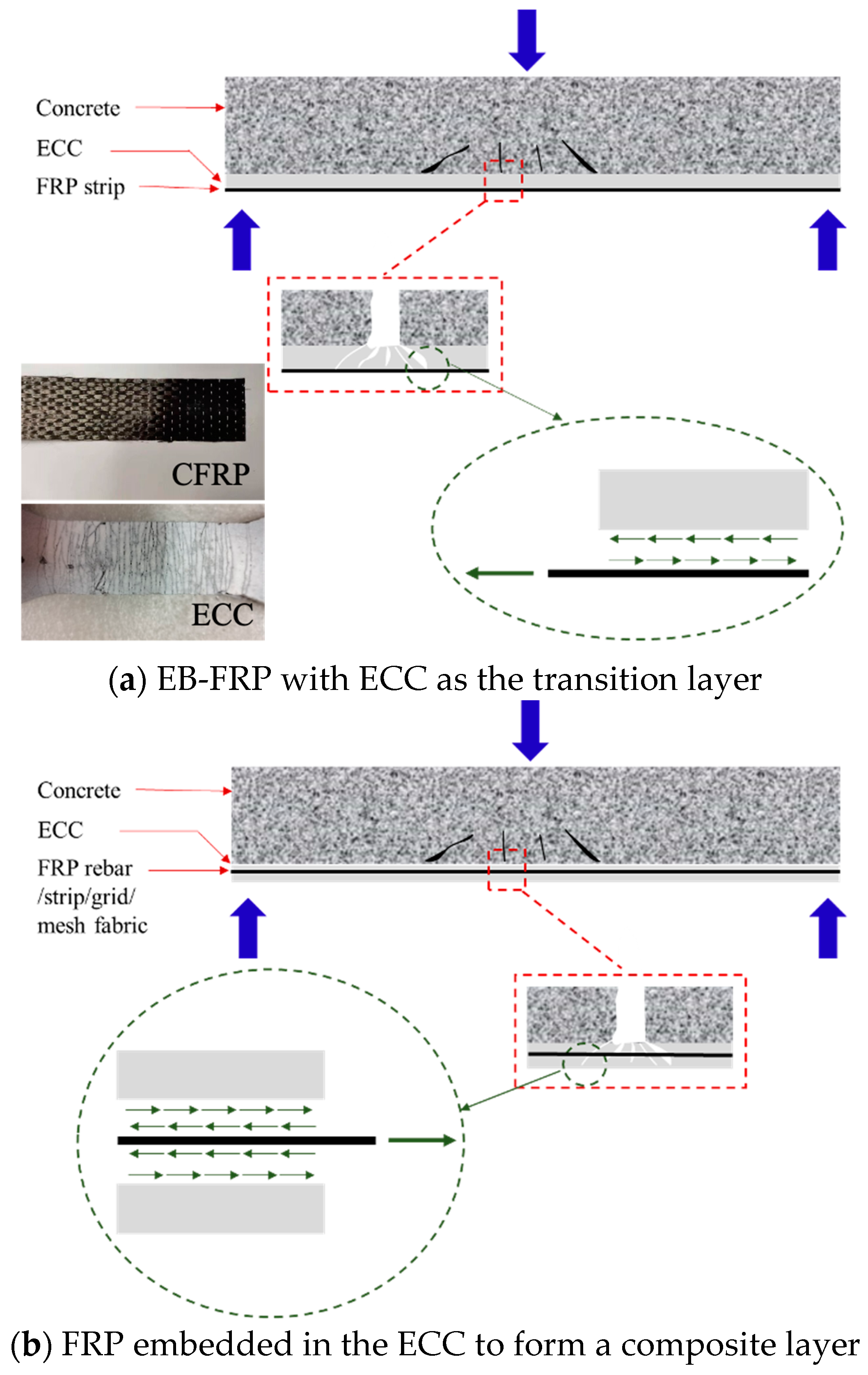
1. Introduction
2. Experimental Program
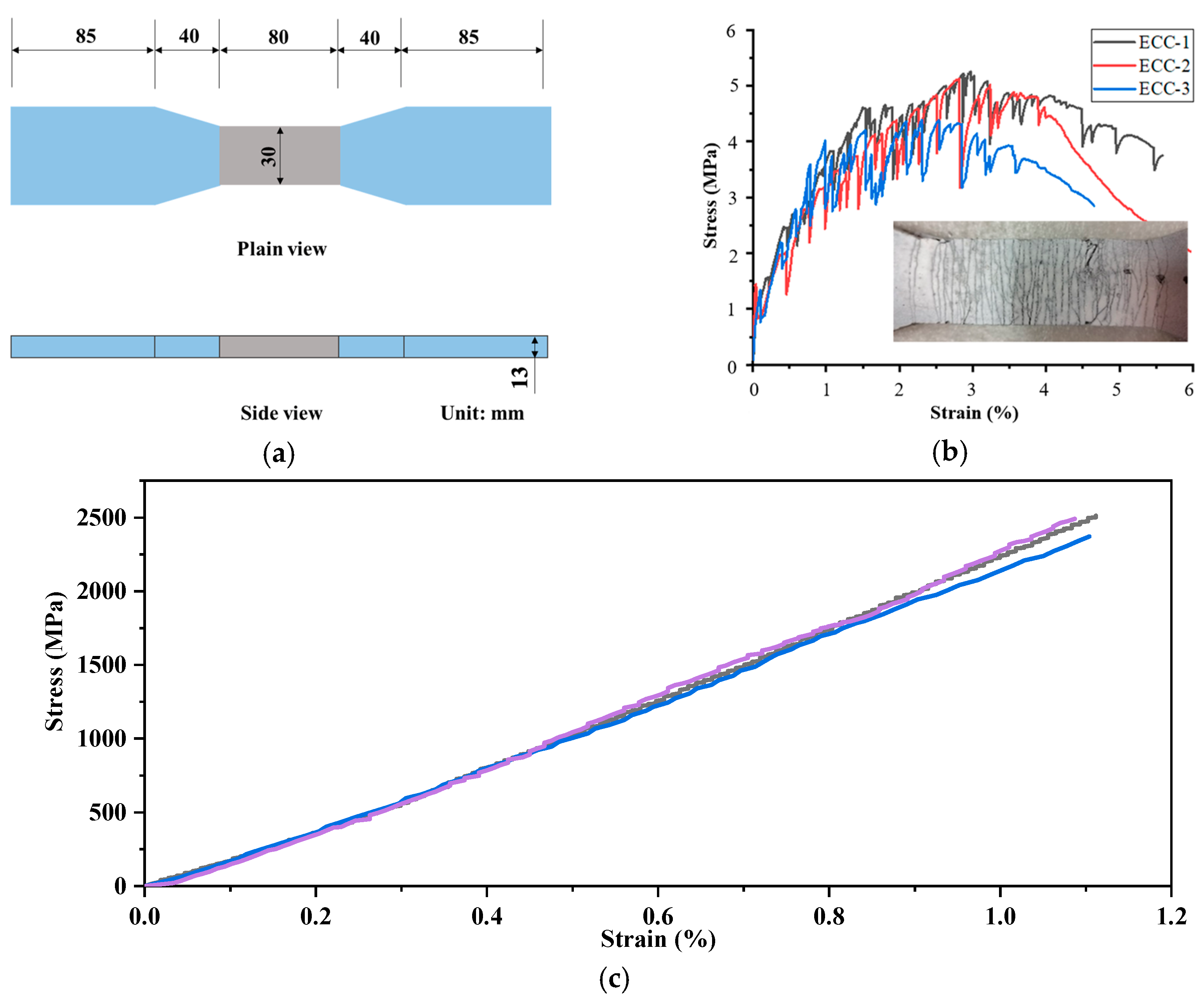
2.1. Material Properties
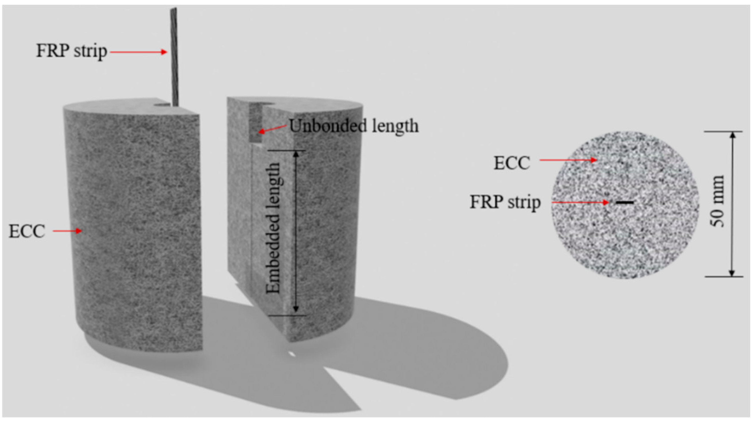
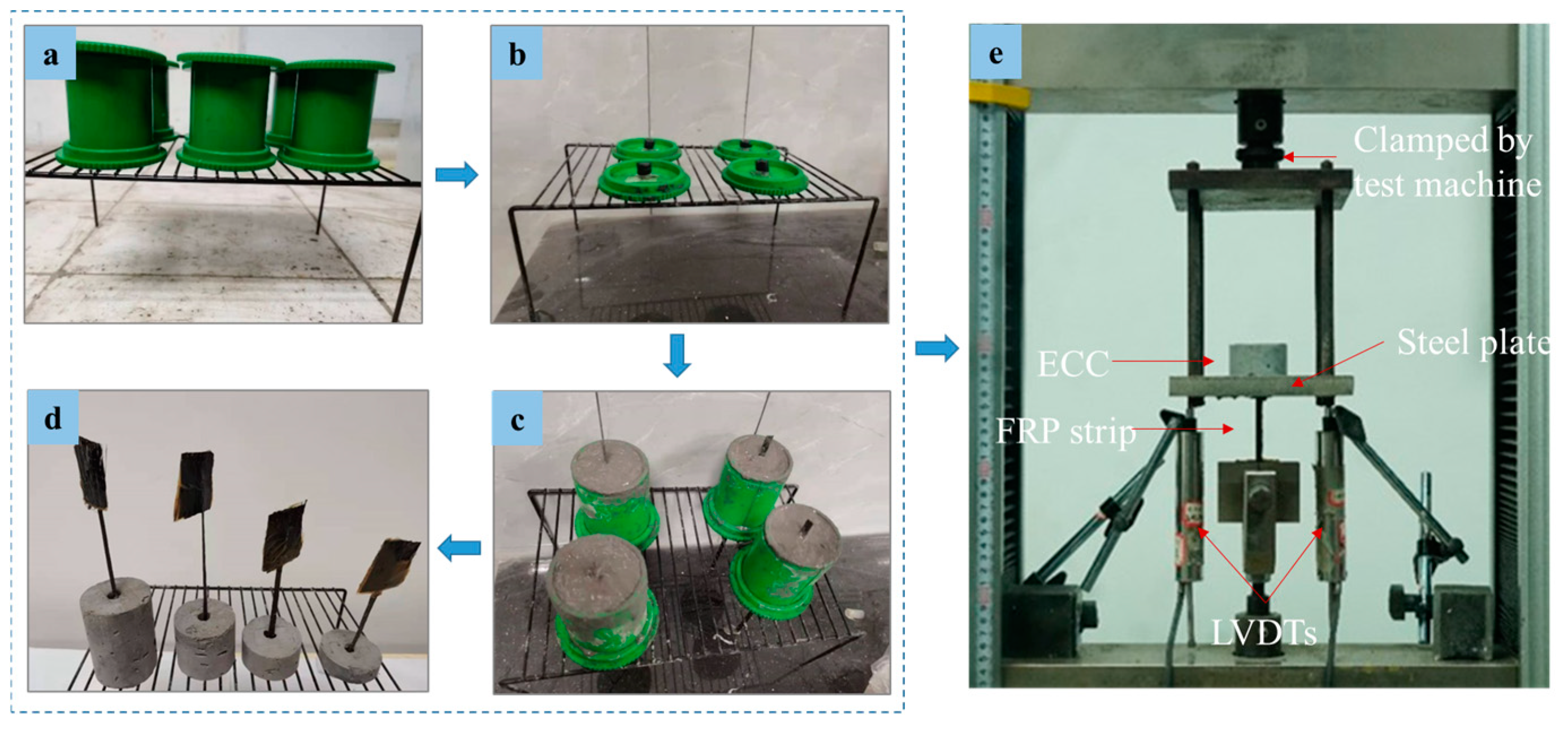
2.2. Specimen and Test Setup
3. Experimental Observation
4. Analytical Extraction of the Bond–Slip Relationship for the FRP Strip–ECC Joints
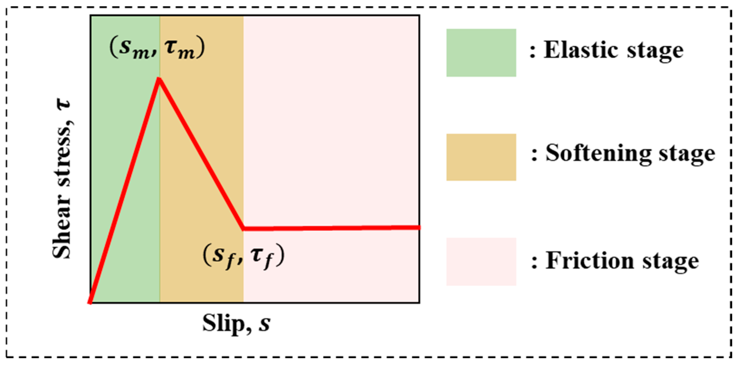
4.1. Trilinear Bond–Slip Relationship
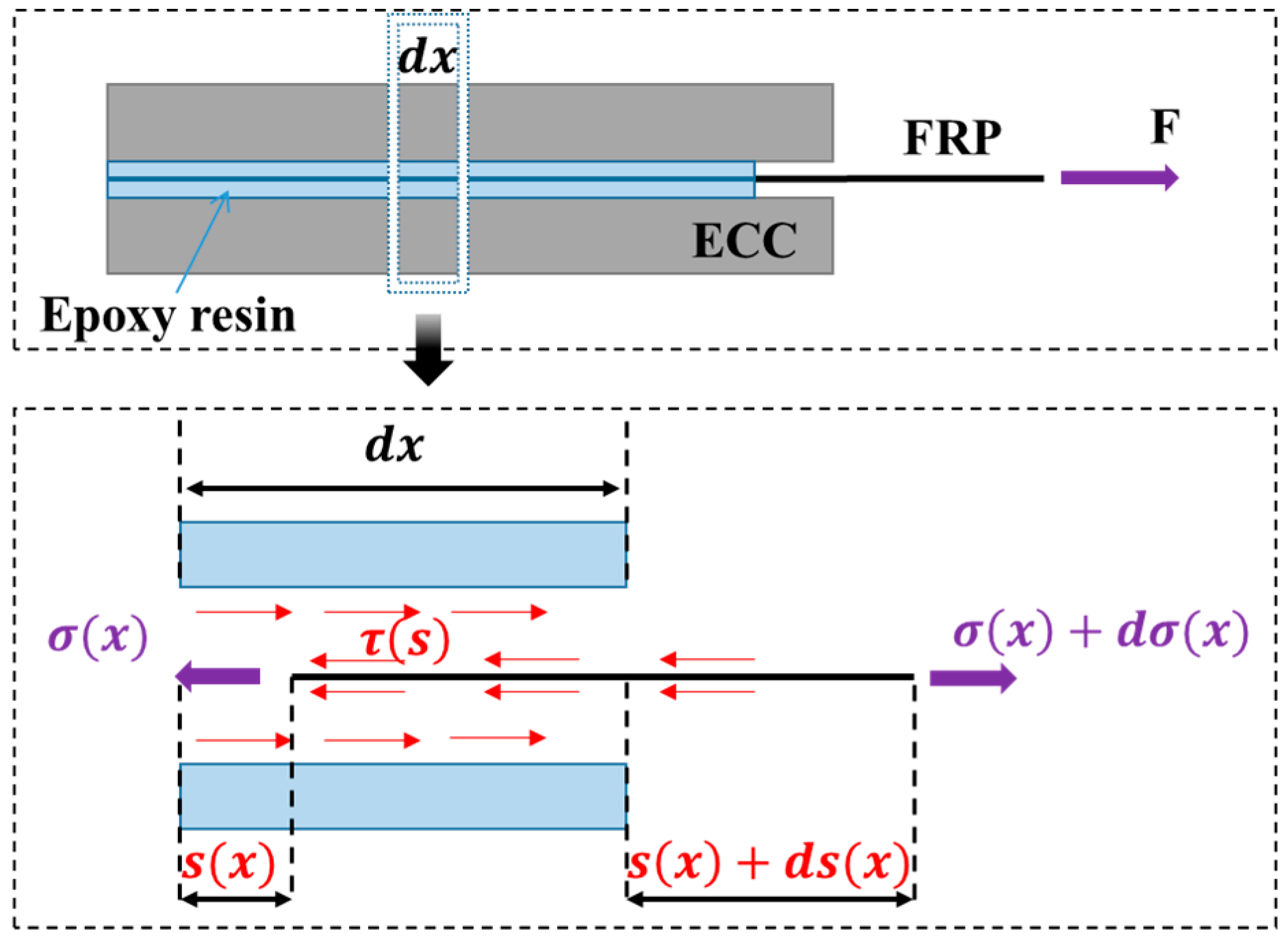
4.2. Analysis of the Full-Range Slid-Out Behavior of FRP Strips in ECC
4.3. Verification and Determination of the Trilinear Bond–Slip Relationship
5. Conclusions
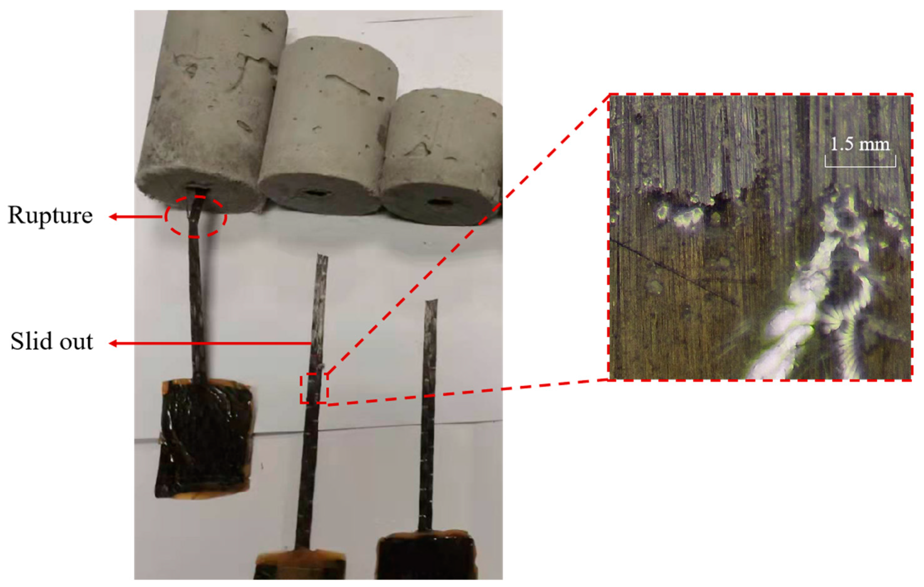
- The epoxy resin remains adhered within the ECC matrix upon the pull-out of the FRP strip, indicating that the embedded FRP strip–ECC joint failure predominantly arises from interlayer shear damage occurring between the fibers and epoxy resin.
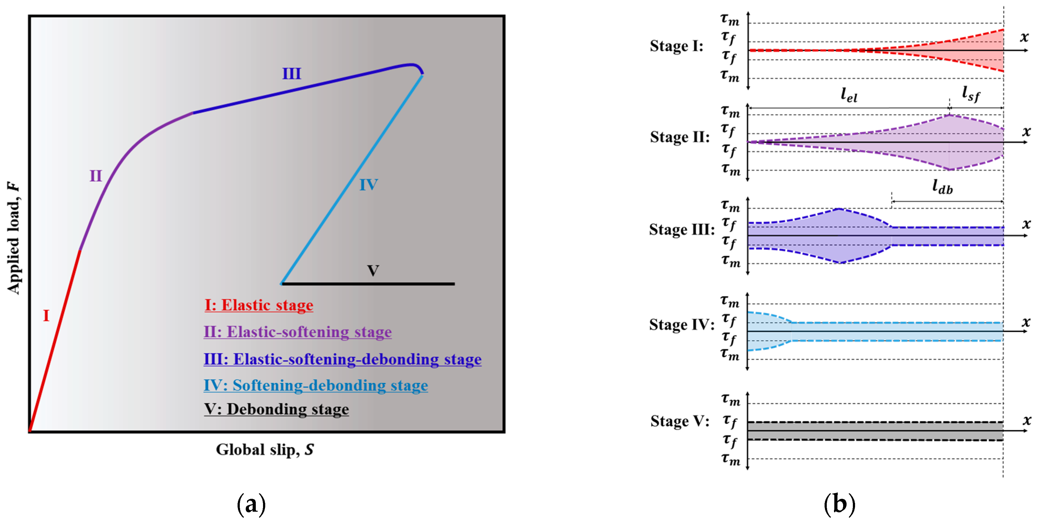
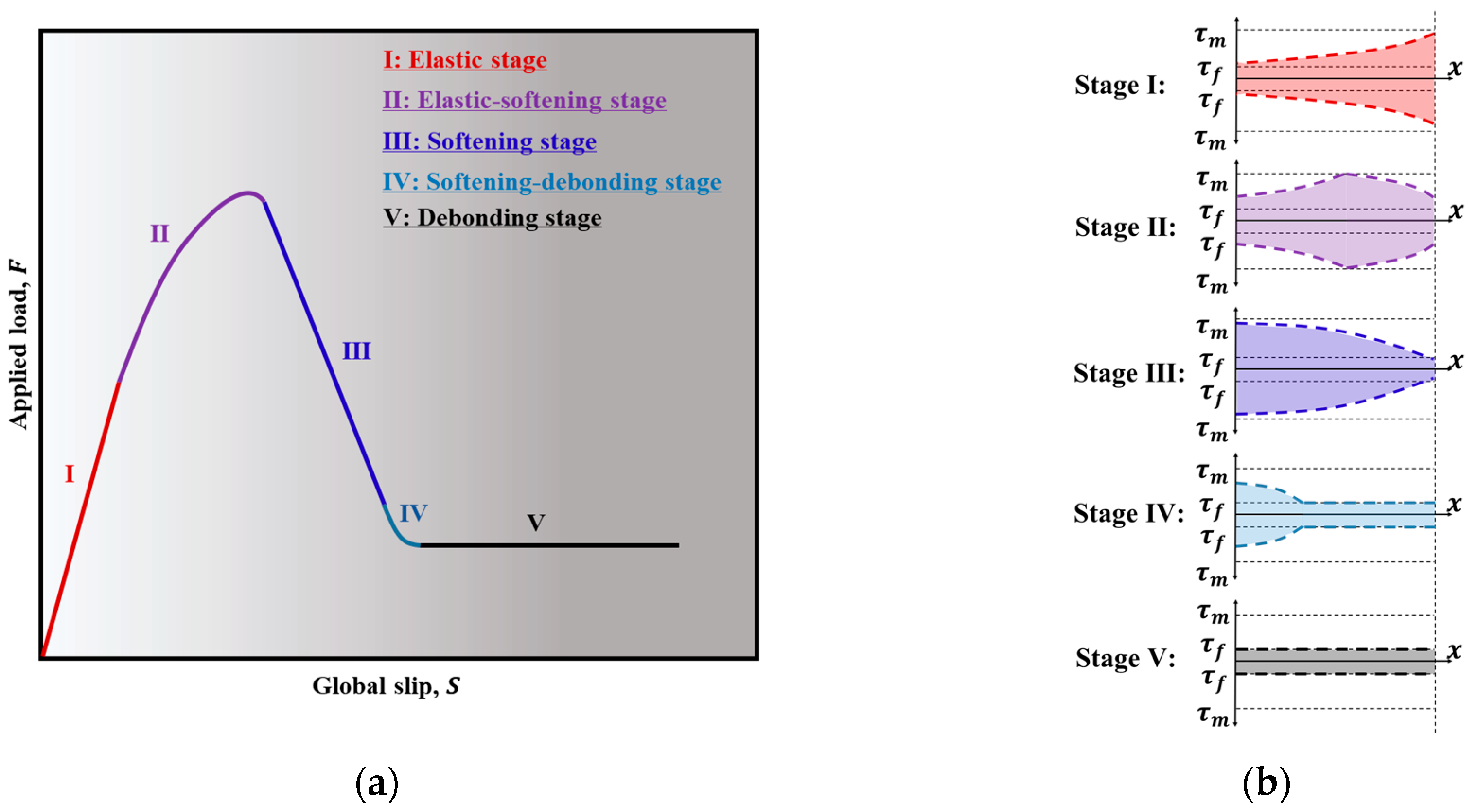
- The F-S behavior for long embedded lengths includes an elastic stage, an elastic-softening stage, an elastic–softening–debonding stage, a softening–debonding stage, and a debonding stage. When the embedded length is shorter than the fully established softening length, the third stage becomes a pure softening stage.
- The theoretical model introduced in this paper can accurately evaluate the pull-out behavior of embedded FRP strips in an ECC. However, the analytical model cannot guarantee accurate consistency with the post-peak behavior of the experimental results, especially when the embedded length is relatively long.
Author Contributions
Funding
Institutional Review Board Statement
Data Availability Statement
Acknowledgments
Conflicts of Interest
References
- Pellegrino, C.; Vasic, M. Assessment of design procedures for the use of externally bonded FRP composites in shear strengthening of reinforced concrete beams. Compos. Part B Eng. 2013, 45, 727–741. [Google Scholar] [CrossRef]
- Mansour, W.; Li, W.W.; Wang, P.; Fame, C.M.; Tam, L.H.; Lu, Y.; Sobuz, M.H.R.; Elwakkad, N.Y. Improving the Flexural Response of Timber Beams Using Externally Bonded Carbon Fiber-Reinforced Polymer (CFRP) Stripss. Materials 2024, 17, 321. [Google Scholar] [CrossRef] [PubMed]
- Ozbakkaloglu, T.; Lim, J.C. Axial compressive behavior of FRP-confined concrete: Experimental test database and a new design-oriented model. Compos. Part B Eng. 2013, 55, 607–634. [Google Scholar] [CrossRef]
- Vedernikov, A.; Tucci, F.; Carlone, P.; Gusev, S.; Konev, S.; Firsov, D.; Akhatov, I.; Safonov, A. Effects of pulling speed on structural performance of L-shaped pultruded profiles. Compos. Struct. 2021, 255, 112967. [Google Scholar] [CrossRef]
- Lu, Y.; Li, W.; Zhou, Y.; Mansour, W.; Zheng, K.; Wang, P.; Ke, L.; Yu, J. Comparative analysis of shear behavior and mechanism of concrete beams with strip-shaped CFRP or conventional steel stirrups. Case Stud. Constr. Mater. 2024, 20, e03140. [Google Scholar] [CrossRef]
- Tran, C.T.N.; Nguyen, X.H.; Nguyen, H.C.; Le, D.D. Shear performance of short-span FRP-reinforced concrete beams strengthened with CFRP and TRC. Eng. Struct. 2021, 242, 112548. [Google Scholar] [CrossRef]
- Bilotta, A.; Faella, C.; Martinelli, E.; Nigro, E. Design by testing procedure for intermediate debonding in EBR FRP strengthened RC beams. Eng. Struct. 2013, 46, 147–154. [Google Scholar] [CrossRef]
- Khalifa, A.; Nanni, A. Improving shear capacity of existing RC T-section beams using CFRP composites. Cem. Conc. Compos. 2000, 22, 165–174. [Google Scholar] [CrossRef]
- Lee, J.Y.; Hwang, H.B.; Doh, J.H. Effective strain of RC beams strengthened in shear with FRP. Compos. Part B Eng. 2012, 43, 754–765. [Google Scholar] [CrossRef]
- Oller, E.; Pujol, M.; Mari, A. Contribution of externally bonded FRP shear reinforcement to the shear strength of RC beams. Compos. Part B Eng. 2019, 164, 235–248. [Google Scholar] [CrossRef]
- Raoof, S.M.; Koutas, L.N.; Bournas, D.A. Textile-reinforced mortar (TRM) versus fibre-reinforced polymers (FRP) in flexural strengthening of RC beams. Constr. Build. Mater. 2017, 151, 279–291. [Google Scholar] [CrossRef]
- Zhou, A.; Qin, R.; Feo, L.; Penna, R.; Lau, D. Investigation on interfacial defect criticality of FRP-bonded concrete beams. Compos. Part B Eng. 2017, 113, 80–90. [Google Scholar] [CrossRef]
- Jamalan, M.H.; Fu, F. Numerical Analysis on Bond Strength of FRP Re-bars under Elevated Temperature. IOP Conf. Ser Mater. Sci. Eng. 2018, 371, 012013. [Google Scholar] [CrossRef]
- Li, Y.; Liu, X.; Li, J. Bond properties of FRP-concrete interface with nano-modified epoxy resin under wet-dry cycles, KSCE. J. Civ. Eng. 2017, 21, 1379–1385. [Google Scholar]
- Liu, W.-H.; Kai, M.-F.; Zhang, P.; Yu, T.; Dai, J.-G. Three-dimensional finite element modeling of debonding failure of skew FRP-bonded concrete joints. Eng. Struct. 2024, 303, 117537. [Google Scholar] [CrossRef]
- Sui, L.L.; Luo, M.S.; Yu, K.Q.; Xing, F.; Li, P.D.; Zhou, Y.W.; Chen, C. Effect of engineered cementitious composite on the bond behavior between fiber-reinforced polymer and concrete. Compos. Struct. 2018, 184, 775–788. [Google Scholar] [CrossRef]
- Li, W.W.; Zhao, J.L.; Huang, X.L.; Zheng, J.; Shi, T.S.; Shumuye, E.D. Mechanical properties of SAC-ECC reinforced with fiber-reinforced polymer mesh. Constr. Build. Mater. 2022, 344, 128279. [Google Scholar] [CrossRef]
- Zhang, P.; Shang, J.Q.; Fan, J.J.; Chen, Q.Z.; Zhu, H.; Gao, D.Y.; Sheikh, S.A. Experimental study on the bond behavior of the CFRP plate-ECC-concrete composite interface under freeze-thaw cycles. Constr. Build. Mater. 2022, 316, 125822. [Google Scholar] [CrossRef]
- Zheng, A.H.; Zong, S.; Lu, Y.Y.; Li, S. Fatigue performance of corrosion-damaged beams strengthened with FRP grid-reinforced ECC matrix composites. Eng. Struct. 2022, 255, 113938. [Google Scholar] [CrossRef]
- Lim, C.; Jeong, Y.; Kim, J.; Kwon, M. Experimental study of reinforced concrete beam-column joint retrofitted by CFRP grid with ECC and high strength mortar. Constr. Build. Mater. 2022, 340, 127694. [Google Scholar] [CrossRef]
- Emara, M.; El-Zohairy, A.; Fekry, M.; Husain, M. Effect of Using ECC Layer on the Flexural Performance of RC Beams Previously Strengthened with EB CFRP Laminates. Sustainability 2022, 14, 16990. [Google Scholar] [CrossRef]
- Al-Gemeel, A.N.; Zhuge, Y.; Youssf, O. Experimental investigation of basalt textile reinforced engineered cementitious composite under apparent hoop tensile loading. J. Build. Eng. 2019, 23, 270–279. [Google Scholar] [CrossRef]
- Zhao, D.B.; Zhou, Y.W.; Xing, F.; Sui, L.L.; Ye, Z.H.; Fu, H.K. Bond behavior and failure mechanism of fiber-reinforced polymer bar–engineered cementitious composite interface. Eng. Struct. 2021, 243, 112520. [Google Scholar] [CrossRef]
- George, M.; Sathyan, D.; Mini, K.M. Investigations on effect of different fibers on the properties of engineered cementitious composites. Mater. Today Proc. 2020, 42, 1417–1421. [Google Scholar] [CrossRef]
- Shanmugasundaram, N.; Praveenkumar, S. Mechanical properties of engineered cementitious composites (ECC) incorporating different mineral admixtures and fibre: A review. J. Build. Pathol. Rehabil. 2022, 7, 40. [Google Scholar] [CrossRef]
- Huang, B.T.; Zhu, J.X.; Weng, K.F.; Li, V.C.; Dai, J.G. Ultra-high-strength engineered/strain-hardening cementitious composites (ECC/SHCC): Material design and effect of fiber hybridization. Cem. Concr. Compos. 2022, 129, 104464. [Google Scholar] [CrossRef]
- Singh, M.; Saini, B.; Chalak, H.D. Performance and composition analysis of engineered cementitious composite (ECC)-A review. J. Build. Eng. 2019, 26, 100851. [Google Scholar] [CrossRef]
- Panganayi, C.; Ogata, H.K.; Hattori, A.M. Anwar, Effectiveness of ECC in curtailing re-emergence of weeds on an earth embankment surface. Constr. Build. Mater. 2010, 24, 545–551. [Google Scholar] [CrossRef]
- Zhou, Y.W.; Sui, L.L.; Huang, X.X.; Guo, M.H.; Luo, M.S.; Hu, B.A.; Chen, C. Enhancing the EB-FRP strengthening effectiveness by incorporating a cracking-control layer of ECC with different thicknesses. Constr. Build. Mater. 2021, 286, 122975. [Google Scholar] [CrossRef]
- Afefy, H.M.; Kassem, N.; Hussein, M. Enhancement of flexural behaviour of CFRP-strengthened reinforced concrete beams using engineered cementitious composites transition layer. Struct. Infrastruct. Eng. 2015, 11, 1042–1053. [Google Scholar] [CrossRef]
- Zheng, Y.Z.; Wang, W.W.; Mosalam, K.M.; Fang, Q.; Chen, L.; Zhu, Z.F. Experimental investigation and numerical analysis of RC beams shear strengthened with FRP/ECC composite layer. Compos. Struct. 2020, 246, 112436. [Google Scholar] [CrossRef]
- Guo, R.; Ren, Y.; Li, M.Q.; Hu, P.; Du, M.; Zhang, R. Experimental study on flexural shear strengthening effect on low-strength RC beams by using FRP grid and ECC. Eng. Struct. 2021, 227, 111434. [Google Scholar] [CrossRef]
- Ren, Y.; Gao, Z.Q.; Xia, M.Y.; Guo, R. Study on bonding behavior of FRP grid-ECC composite layer and concrete with quantitative interface treatment. Eng. Struct. 2023, 294, 116768. [Google Scholar] [CrossRef]
- Al-Gemeerl, A.N.; Yan, Z.G. Using textile reinforced engineered cementitious composite for concrete columns confinement. Compos. Struct. 2019, 210, 695–706. [Google Scholar] [CrossRef]
- Jiang, J.F.; Jiang, C.; Li, B.B.; Feng, P. Bond behavior of basalt textile meshes in ultra-high ductility cementitious composites. Compos. Part B Eng. 2019, 174, 107022. [Google Scholar] [CrossRef]
- Li, W.W.; Lu, Y.; Shi, T.S.; Wang, P. A novel double bridging-slipping (DBS) concept to overcome deformation incompatibility of textile reinforced-engineering cementitious composite (TR-ECC). Case Stud. Constr. Mater. 2023, 19, e02475. [Google Scholar] [CrossRef]
- Kai, M.F.; Dai, J.G. Understanding geopolymer binder-aggregate interfacial characteristics at molecular level. Cement. Concrete. Res. 2021, 149, 106582. [Google Scholar] [CrossRef]
- Deng, L.N.; Li, T.S.; Zhong, M.J.; Liao, L.; Li, H. Bond Stress-Slip Model of BFRP Grid to ECC. Materials 2022, 15, 7965. [Google Scholar] [CrossRef]
- Xu, L.; Wang, X.Y.; Pan, J.L.; Zhou, J.J.; Liu, W.R. Bond behavior between steel-FRP composite bars and engineered cementitious composites in pullout conditions. Eng. Struct. 2024, 299, 117086. [Google Scholar] [CrossRef]
- Concrete Committee JSCE. Recommendations for Design and Construction of High Performance Fiber Reinforced Cement Composites With Multiple Fine Cracks (HPFRCC); Japan Society of Civil Engineers: Tokyo, Japan, 2008. [Google Scholar]
- GB/T 3354-2014; Test Method for Tensile Properties of Orientation Fiber Reinforced Polymer Matrix Composite Materials. National Standards of the People’s Republic of China: Beijing, China, 2014. (In Chinese)
- Lin, H.W.; Zeng, H.X.; Feng, P.; Jiang, C.; Zhang, Y.Q. Bond behavior of FRP-concrete wet-bonding interface under lateral confinement. Eng. Struct. 2023, 292, 116536. [Google Scholar] [CrossRef]
- Qian, S.; Li, V.C. Influence of concrete material ductility on headed anchor pullout performance. ACI Mater. J. 2009, 106, 72–81. [Google Scholar]
- Zhou, Y.W.; Fu, H.K.; Li, P.D.; Zhao, D.B.; Sui, L.L.; Li, L. Bond behavior between steel bar and engineered cementitious composite (ECC) considering lateral FRP confinement: Test and modeling. Compos. Struct. 2019, 226, 111206. [Google Scholar] [CrossRef]
- Zou, X.X.; Sneed, L.H.; D’Antino, T. Full-range behavior of fiber reinforced cementitious matrix (FRCM)-concrete joints using a trilinear bond-slip relationship. Compos. Struct. 2020, 239, 112024. [Google Scholar] [CrossRef]
- Carozzi, F.G.; Colombi, P.; Fava, G.; Poggi, C. A cohesive interface crack model for the matrix–textile debonding in FRCM composites. Compos. Struct. 2016, 143, 230–241. [Google Scholar] [CrossRef]
- Zhang, M.; Deng, M.K. Fabric-to-cementitious matrix bond behavior in carbon fabric reinforced cementitious matrix (FRCM) composites with added short fibers. Compos. Struct. 2022, 300, 116173. [Google Scholar] [CrossRef]
- Huang, P.M.; Sun, Y.M.; Mei, K.H.; Wang, T. A theoretical solution for the pullout properties of a single FRP rod embedded in a bond type anchorage. Mech. Adv. Mater. Struc. 2020, 27, 304–317. [Google Scholar] [CrossRef]
- Wu, Y.F.; Xu, X.S.; Sun, J.B.; Jiang, C. Analytical solution for the bond strength of externally bonded reinforcement. Compos. Struct. 2012, 94, 3232–3239. [Google Scholar] [CrossRef]


| Water | Cement | Fly Ash | Silica Sand | PE Fiber | Superplasticizer |
|---|---|---|---|---|---|
| 400.00 | 533.30 | 400.00 | 266.60 | 15.00 | 4.00 |
| SiO2 | Al2O3 | Fe2O3 | CaO | Others | |
|---|---|---|---|---|---|
| Fly ash | 45.20 | 26.10 | 6.93 | 11.84 | 9.93 |
| Cement | 17.94 | 4.46 | 3.56 | 64.56 | 9.48 |
| Fiber Length | Diameter | Young’s Modulus | Elongation | Tensile Strength | Density |
|---|---|---|---|---|---|
| (mm) | (μm) | (GPa) | (%) | (MPa) | (g/cm3) |
| 18 | 20 | 100 | 3 | 3000 | 0.97 |
| Type | Width | Thickness | Ultimate TensileStrength | Rupture Strain | Elastic Modulus |
|---|---|---|---|---|---|
| (mm) | (mm) | (MPa) | (%) | (GPa) | |
| CFRP | 5.4 | 0.167 | 2462.96 | 1.10 | 218.79 |
| Specimens ID | FRP Type | Embedded Length (mm) | Number | Failure Mode |
|---|---|---|---|---|
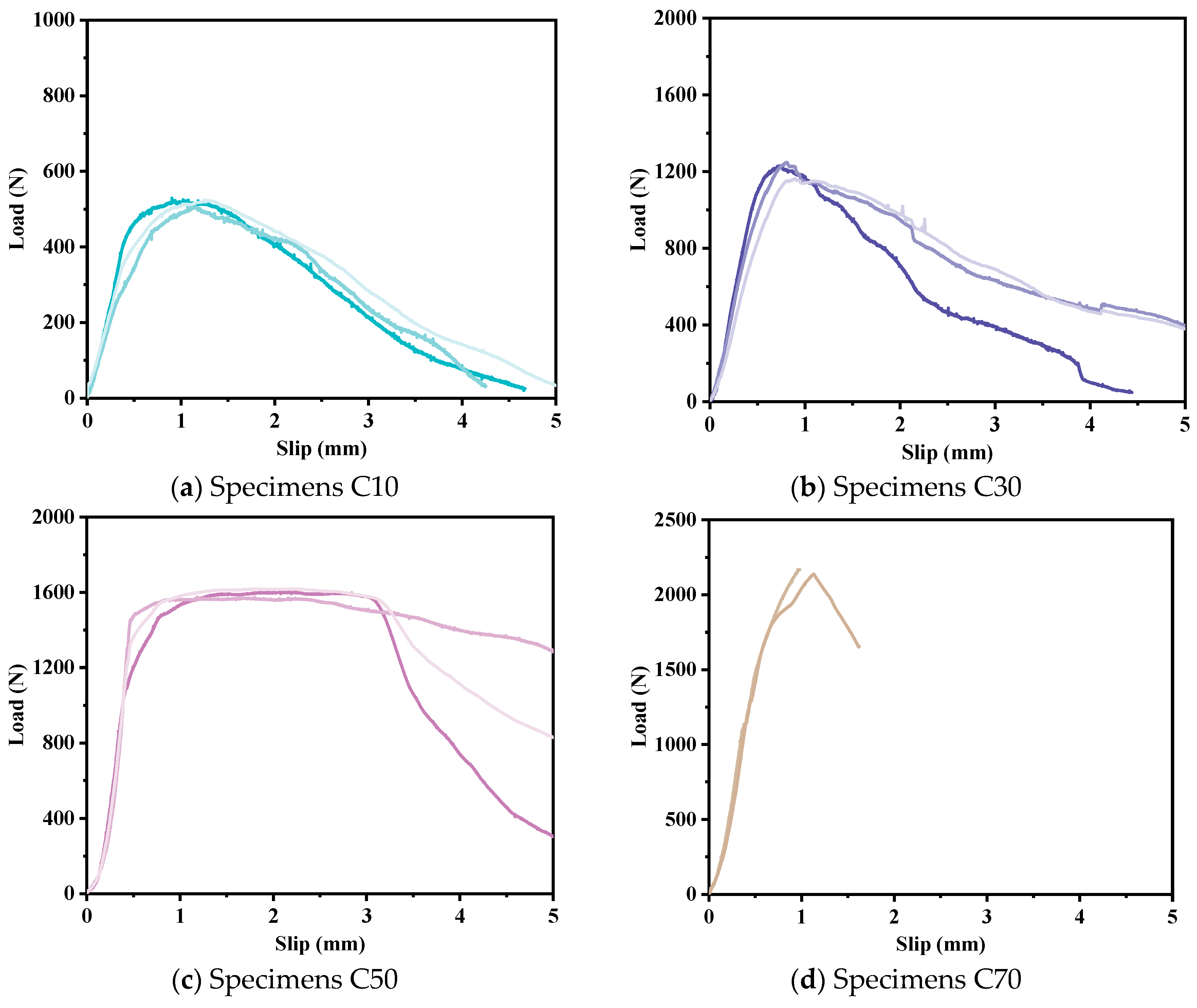
| C10 | CFRP strip | 10 | 3 | Slid out |
| C30 | CFRP strip | 30 | 3 | Slid out |
| C50 | CFRP strip | 50 | 3 | Slid out |
| C70 | CFRP strip | 70 | 2 | FRP rupture |
| (mm) | (MPa) | (mm) | (MPa) |
|---|---|---|---|
| 0.201 | 5.19 | 1.305 | 1.71 |
Disclaimer/Publisher’s Note: The statements, opinions and data contained in all publications are solely those of the individual author(s) and contributor(s) and not of MDPI and/or the editor(s). MDPI and/or the editor(s) disclaim responsibility for any injury to people or property resulting from any ideas, methods, instructions or products referred to in the content. |
© 2025 by the authors. Licensee MDPI, Basel, Switzerland. This article is an open access article distributed under the terms and conditions of the Creative Commons Attribution (CC BY) license (https://creativecommons.org/licenses/by/4.0/).
Share and Cite
Li, W.; Fang, W.; Lu, Y.; Li, W.; Yang, J.; Wang, H.; Wang, P.; Wang, Y.; Cui, H. Bonding Properties of Embedded Fiber Reinforced Polymer Strip-Engineered Cementitious Composite Joints. Polymers 2025, 17, 1049. https://doi.org/10.3390/polym17081049
Li W, Fang W, Lu Y, Li W, Yang J, Wang H, Wang P, Wang Y, Cui H. Bonding Properties of Embedded Fiber Reinforced Polymer Strip-Engineered Cementitious Composite Joints. Polymers. 2025; 17(8):1049. https://doi.org/10.3390/polym17081049
Chicago/Turabian StyleLi, Weiwen, Wujun Fang, Yao Lu, Wanye Li, Jingming Yang, Hao Wang, Peng Wang, Yaocheng Wang, and Hongzhi Cui. 2025. "Bonding Properties of Embedded Fiber Reinforced Polymer Strip-Engineered Cementitious Composite Joints" Polymers 17, no. 8: 1049. https://doi.org/10.3390/polym17081049
APA StyleLi, W., Fang, W., Lu, Y., Li, W., Yang, J., Wang, H., Wang, P., Wang, Y., & Cui, H. (2025). Bonding Properties of Embedded Fiber Reinforced Polymer Strip-Engineered Cementitious Composite Joints. Polymers, 17(8), 1049. https://doi.org/10.3390/polym17081049