1. Introduction
Bio-based materials have gained prominence as sustainable alternatives to fossil-based products, aiming to mitigate the environmental impact of human activities [
1,
2,
3]. Sourced from trees and plants, these materials support the development of eco-friendly structures capable of bearing loads. Notably, natural fiber composites—such as flax, jute, and palm tree fibers—exhibit significant potential for diverse applications. Within this realm, wood, a renewable natural resource that has been utilized for centuries across various domains, warrants particular consideration [
4].
Wood has many noteworthy attributes that make it a highly attractive material choice, such as its versatility, durability, resistance, robustness, low weight, abundance, and economic viability. Furthermore, wood can adapt to changing forms under different environmental conditions, such as temperature, loading, and moisture, resulting in intricate artifacts with refined geometries [
5,
6]. Wood’s ability to transform in response to its surroundings adds value to its utility and enables innovative applications that exploit its unique properties. In this era of sustainability-driven innovation, wood and other plant-based materials play a vital role in creating a greener and more resource-conscious future. Wood is a natural composite material that, like most composites, is sensitive to holes and notches. Therefore, traditional joining methods such as riveting and bolting are unsuitable for wood [
7,
8]. Adhesive bonding is an effective method for joining wood components, as it minimizes stress concentrations while providing a larger, more evenly distributed bonded area. Although adhesive joints are primarily designed to withstand shear forces, when two substrates are overlapped and subjected to opposing forces, these forces align, generating a flexural moment at the overlap ends. This results in localized stress concentrations and alters the adhesive’s stress distribution from pure shear to a combination of shear and tensile forces. This phenomenon highlights the complex interactions that adhesive joints experience under different loading conditions [
9,
10]. The cohesive properties of the adhesive and the adhering substrates determine the failure load and mode of the joint. Peel loading is especially problematic for adhesive joints with wood substrates, as it causes delamination between different grain layers and leads to joint failure. To address this problem, researchers have proposed various methods, such as densification, substrate toughening, and physical modifications of the adhesive. These methods aim to prevent delamination and enhance the strength of adhesive joints with wood substrates. The use of adhesives for bonding wood substrates requires a careful approach to ensure the design of effective, safe, and high-performance modern wooden structures. With the increasing application of wooden structures in various fields, such as vehicular engineering, several physical and chemical modifications have been developed to enhance the mechanical properties of these materials. Consequently, adhesively bonded joints have become popular in different industries, such as civil, automotive, and aeronautical engineering, due to their advantages over traditional joints. Recent studies have focused on improving the performance of wooden adhesive joints by using bio-adhesives and wood-based substrates. The main objective of these studies was to characterize these materials and integrate them into adhesive joints. However, a major challenge is the durability of bio-adhesives under harsh environmental conditions, such as high temperature and humidity, over a long service life [
11,
12].
Addressing this durability challenge assumes significance as it ultimately determines the practicality and longevity of the adhesive joints in real-world scenarios. The failure mode and load capacity of joints are significantly influenced by the properties of both the adhesive and the substrate. Composite materials commonly face a challenge related to the strength of their matrix, particularly when exposed to peel stress. This arises because the fibers within the matrix may not reach their optimal efficiency [
13,
14]. Therefore, any method that enhances the peeling strength of the wood directly contributes to the overall strength of the joints [
10].
The durability of a given bio-adhesive and its additives is still an unexplored path. Tian et al. [
15] tried to increase the humidity resistance of soy-protein films by adding polyurethane or natural rubber to the film. Usually, humidity studies involve exposing a thin material plate to a certain humidity condition and measuring its mass changes. However, this method did not work for these films. Instead, the hydrophilicity of the film surface was measured by the contact angle, which showed that adding polyurethane or natural rubber can make the material more hydrophobic and, therefore, more moisture-resistant. Moreover, the thermal stability of soy-based materials was improved by adding inorganic fillers [
10,
16].
Altuna et al. [
17] studied the effect of soybean oil (ESO) on the properties of epoxy resins cured with diglyceryl ether of bisphenol A (DGEBA). The results showed that increasing the ESO content led to a decrease in the storage modulus and glass transition temperature (Tg) of the adhesive. At 100% ESO, the Tg was almost half of that at 0% ESO. This indicates that adding ESO can make the material rubbery at room temperature, which limits its use in applications that require a strong and stiff material.
Baumberger et al. [
18] investigated films containing up to 30% kraft lignin and starch which were produced using extrusion and thermal molding. The mechanical properties of the composite were assessed through tensile testing at two different humidity levels. The study revealed that at 58% relative humidity (RH), lignin enhanced both the strength and strain-to-failure of the composite for lignin contents up to 20%. However, at 71% RH, lignin had the opposite effect on the composite’s properties across the 0% to 30% content range. It was also noted that lignin reduced the films’ water affinity, a behavior attributed to the interplay between the hydrophilic starch matrix and the hydrophobic lignin. This characteristic raises concerns in adhesives with additives, as the adhesive matrix is typically more hydrophilic than the reinforcement, making the adhesive/reinforcement interface a potential pathway for water diffusion [
19].
One way to improve the peel strength of single-lap joints (SLJ) is by using a matrix with high transverse toughness, which enhances resistance to peel stress. This approach can be complemented by additional techniques designed to minimize local stress concentrations in the composite adherends [
20,
21]. Ramezani et al. [
22] investigated the strength of hybrid composite joints reinforced with various laminate materials. They reviewed several methods to improve SLJ strength, including transverse toughening and high-toughness matrix techniques. The study utilized composite adherends and different laminates, such as aluminum, polymeric, and thin-ply. They found that thin-ply laminates increased joint strength by 10% and reduced peel stress at the overlap ends. The authors suggested that hybrid composite joints with different laminate materials offer benefits in terms of weight savings, damage resistance, and load transfer performance.
Shang et al. [
14] proposed a methodology to address delamination issues in adhesive joints with composite substrates. Their investigation included both experimental and numerical evaluations of joint strength, failure modes, and stress distribution within SLJs. The toughened composite material resulted in a significant 22% increase in joint strength and a shift in failure mode from adherend delamination to cohesive failure within the adhesive. The study’s findings indicate that toughened composite materials can effectively mitigate delamination in adhesive joints involving composite substrates while enhancing overall performance.
Bliem et al. [
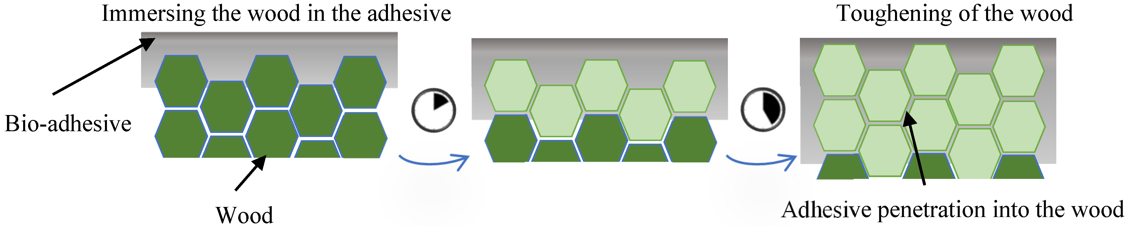
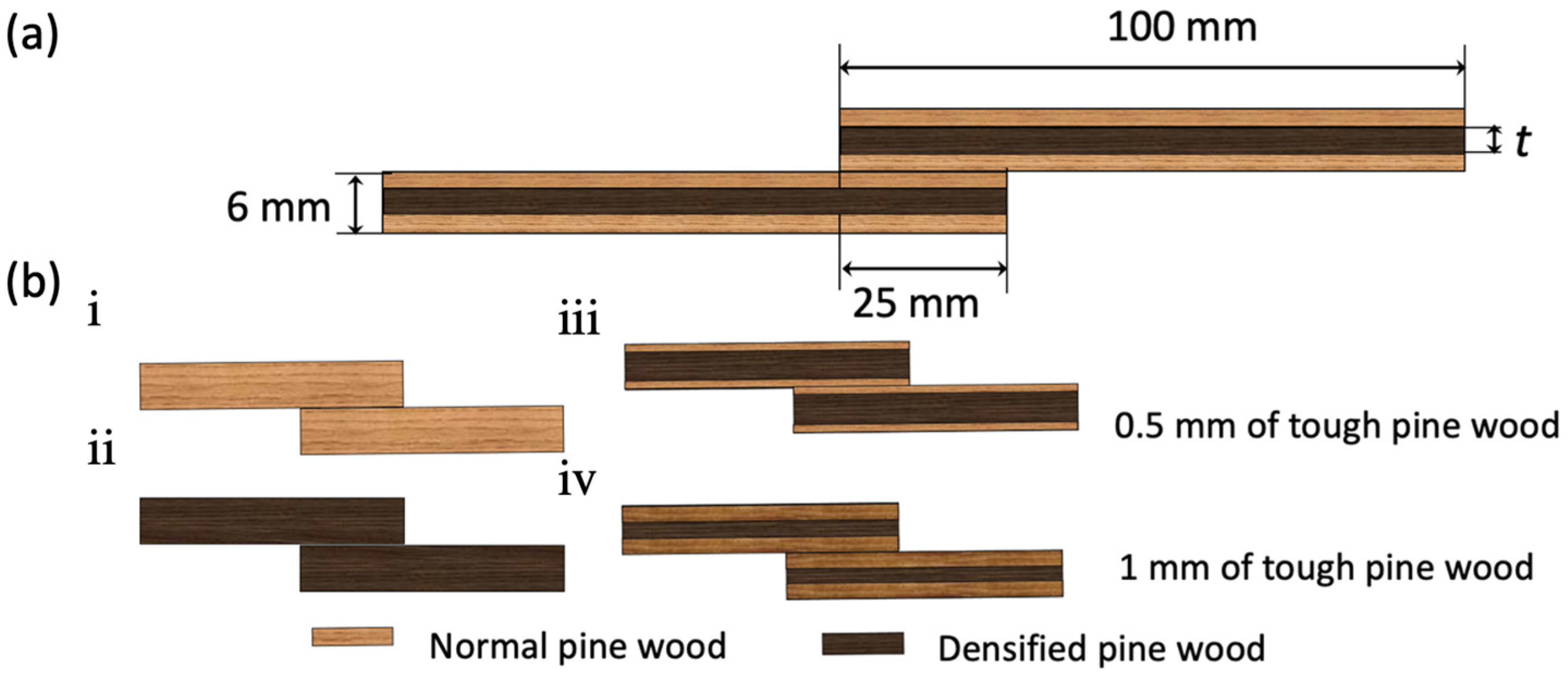
23] investigated the effects of drying temperature, pressing time, and pressing temperature on the shear and tensile strength of wooden single-lap joints. The first step involved keeping the joints at 60 °C and 95 °C for four hours, and the results showed that the 60 °C temperature had no effect on joint strength, while higher temperatures resulted in the degradation of joint strength due to the wood drying. In the second step, the samples were cured at 120 °C and 200 °C for the same duration, and it was found that higher curing temperatures led to a reduction in joint strength due to hemicellulose degradation, while an increase in pressing time caused a change in the failure mode from cohesive to wood delamination. The durability of bio-adhesives and their additives is a poorly understood topic. This study presents a novel technique to improve the mechanical performance of bio-based single-lap joints (SLJs) made of wood substrates and a polyurethane-based bio-adhesive. Wood has some limitations, such as low shear and peel strength, which restrict its use in load-bearing structures. To address this issue, a method to reinforce the wood substrates with bio-adhesive was proposed. This method uses plant-based materials that have high bonding strength and biodegradability. By applying the bio-adhesive on the surface of the wood substrates, the shear and peel strength of the SLJs can increase, as well as the absorbed energy during failure. Experimental tests were performed to evaluate the effectiveness of this technique, comparing it to conventional SLJs made from non-toughened pine wood substrates. A numerical model was also developed to explain the mechanisms behind the mechanical behaviors observed.
4. Results and Discussion
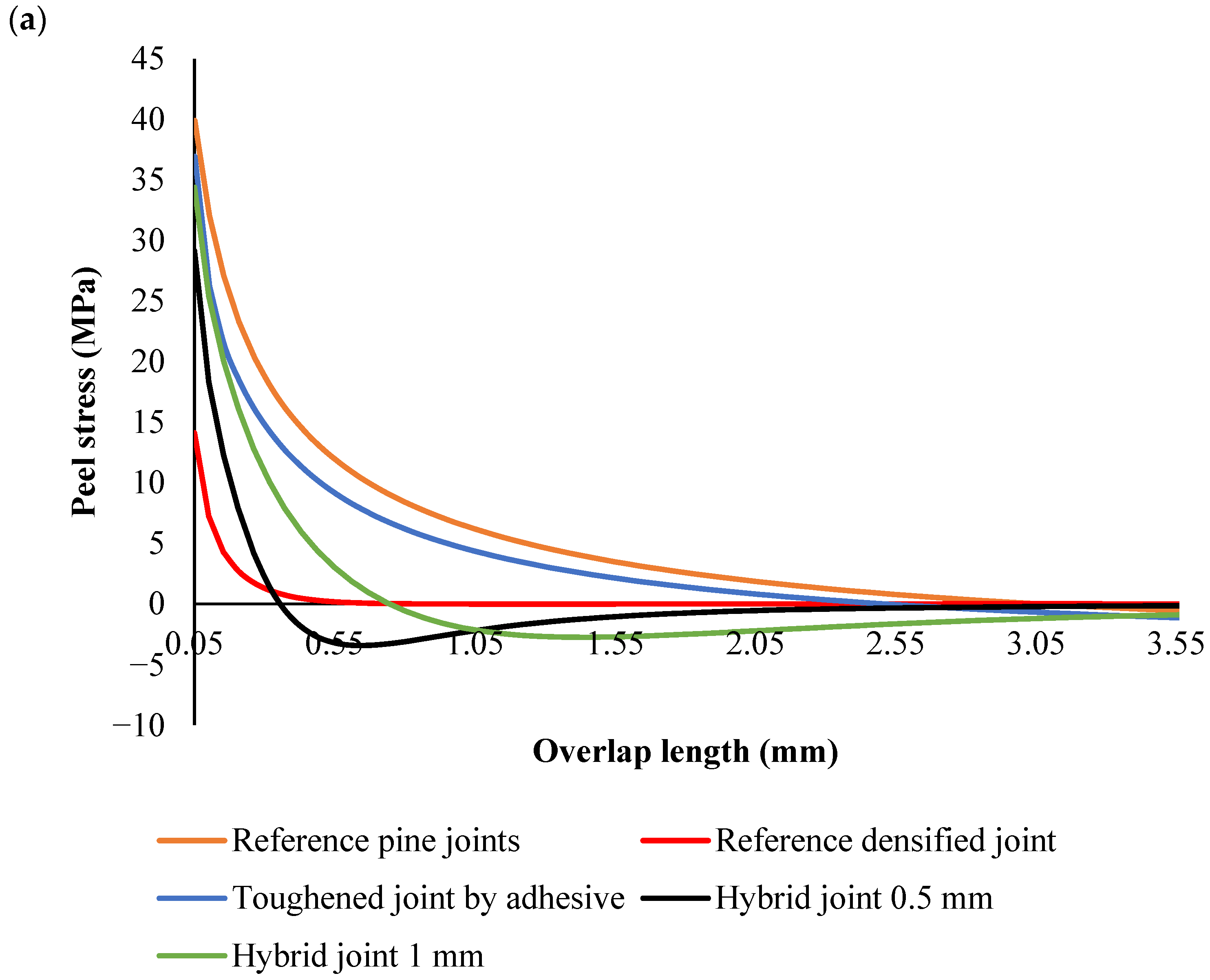
In this section, the peel stress distribution of adhesive single-lap joints with various wood-based substrates is first discussed. Subsequently, the intermediate rate and quasi-static behaviors of the joints are presented. Finally, the fracture surfaces are analyzed to understand the failure mechanisms. The peel stress behavior of these joints was examined under both dynamic and static loading conditions to evaluate the effects of substrate modifications on the performance of the adhesive joints. For the dynamic case, stress distribution was captured at a displacement of 0.5 mm, while for the static case, it was analyzed under a constant applied load. Various configurations of wood-based substrates were considered, and the fracture surfaces were studied to correlate the stress distribution with the observed failure modes.
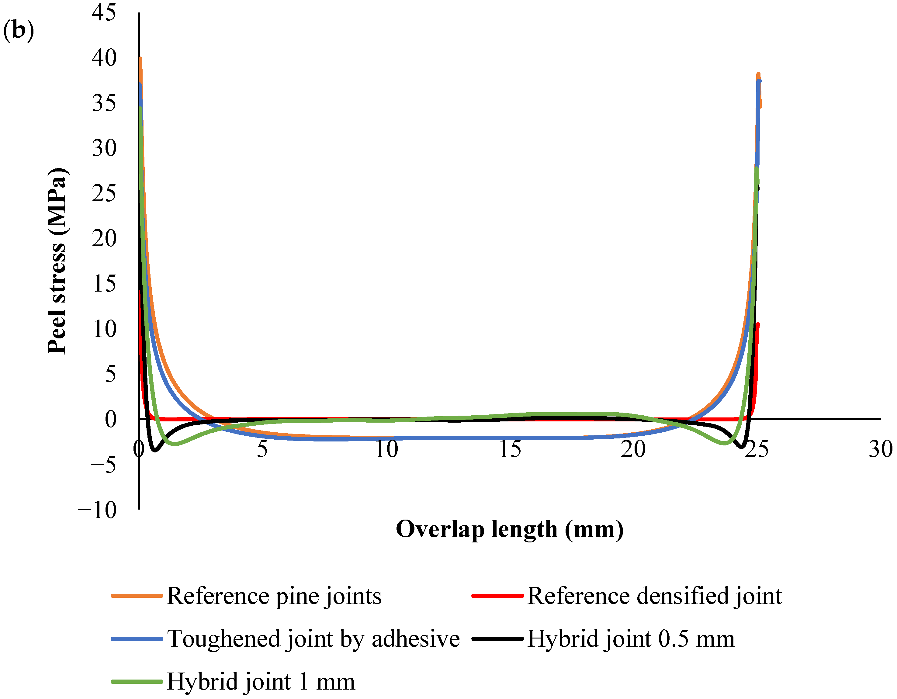
Peel stress analysis under static loading conditions
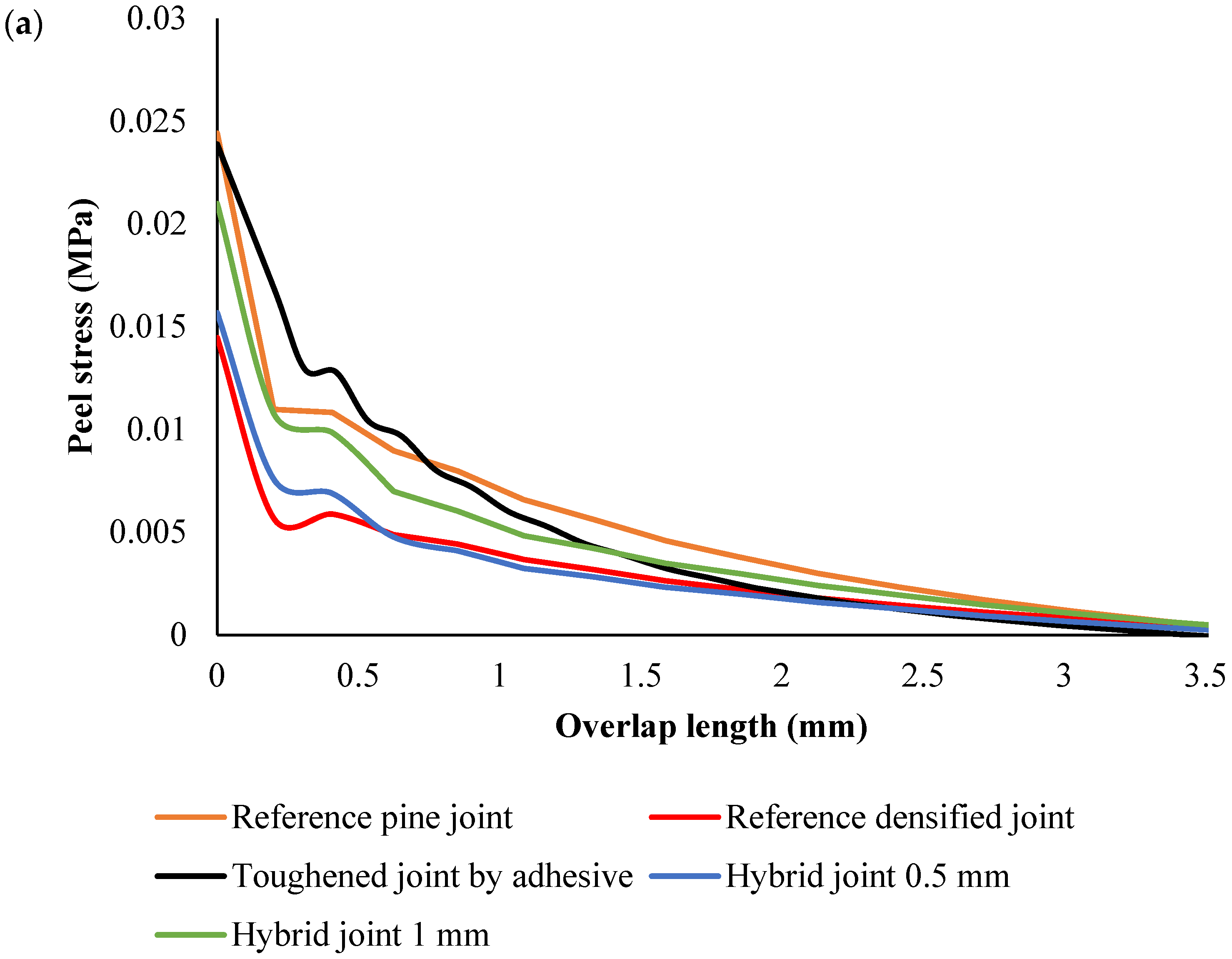
Under static loading conditions, the trends were consistent with the dynamic case, with some differences in the peak stress values (
Figure 7 and
Figure 8). Reference pine exhibited the highest peak stress, indicating that under constant load, the pine wood substrate’s low stiffness led to greater stress concentrations near the overlap edges. This suggests that, under static conditions, untreated pine wood also has a higher risk of early failure at the overlap edges due to its greater susceptibility to deformation.
The toughened pine wood also showed reduced peak stress under static loading. The material’s increased toughness helped to distribute the load more evenly, resulting in lower peak stresses and a more even stress distribution along the overlap. Similarly, the densified pine wood exhibited the lowest peak stress, reflecting its higher stiffness and better ability to resist deformation under static loads, which led to a more uniform stress profile and reduced edge stress concentrations.
In the hybrid configurations, the static analysis showed similar behavior to the dynamic case. The hybrid joints with 0.5 mm thick toughened outer plies exhibited a relatively low peak stress, with a more even stress distribution. The hybrid joints with 1 mm thick toughened plies showed slightly higher peak stresses near the overlap edges compared to the 0.5 mm hybrid joints, but both configurations performed well in terms of distributing the load and reducing stress concentrations across the overlap. The hybrid design again demonstrated its ability to mitigate stress concentration and enhance joint performance, with a more balanced distribution of stress compared to the other configurations.
Peel stress analysis under dynamic loading conditions
In the joints where reference pine wood was used as the substrate, peel stress exhibited the highest peak compared to all other configurations. The pine wood’s relatively low stiffness and flexibility led to substantial deformation under load. This deformation caused a sharp concentration of peel stress near the overlap edges, which is a typical behavior for materials with lower stiffness. The stress then dissipated gradually along the overlap as the pine wood deformed and spread the load. The high peak stress in this configuration indicates a greater susceptibility to failure at the overlap edges, where the stress concentration is most pronounced (
Figure 9).
The toughening of pine wood was where the substrate was treated to absorb adhesive, making the wood tougher and more rigid. The toughened wood resulted in a reduction in peak peel stress compared to the reference pine wood. The adhesive absorption increased local stiffness, which helped mitigate the deformation near the overlap edges and led to a more even distribution of stress. While the peak stress was lower than in the reference joints, it was still relatively high compared to the other configurations, highlighting the improvement in material toughness but still exhibiting some stress concentration near the edges.
The densified pine joints had a much higher stiffness than both untreated and toughened pine wood, and as expected, the peak peel stress was the lowest among all the configurations. The high stiffness of the densified substrate resulted in less deformation under load, leading to a more even stress distribution (
Figure 9). The densified wood resisted significant deformation, and while the stress concentrated near the overlap edges, it did so at a lower level than in the other configurations. This indicates that densified wood is more efficient at handling the applied load and reducing the likelihood of failure caused by stress concentration at the edges of the overlap.
In the hybrid design, a densified core and 0.5 mm thick toughened outer plies were used. The hybrid structure combined the high stiffness of the densified core with the flexibility and toughness of the toughened outer plies. The peak peel stress in this configuration was lower than in the densified wood alone, indicating that the addition of toughened outer plies helped distribute the stress more evenly across the overlap. A noticeable feature of this configuration was the negative peel stress near the overlap edges. This compressive stress near the edges is beneficial because it counteracts the tensile peel forces, which can cause adhesive failure or delamination. The tougher outer plies absorbed some of the stress, improving the overall load distribution and reducing the risk of failure at the overlap edges (
Figure 9).
The hybrid joints, which used a densified core with 1 mm thick toughened outer plies, showed the lowest peak peel stress among all the configurations. The thicker outer plies helped redistribute the stress more effectively, leading to the most uniform stress profile across the overlap. The negative peel stress near the overlap edges was more pronounced in this configuration, further reducing the likelihood of adhesive failure and promoting a more durable adhesive bond. The thicker toughened plies in this configuration enhanced the stress redistribution even more, leading to a lower peak stress and a better overall performance in terms of both strength and durability.
Across all configurations, the stress distribution followed similar trends (
Figure 8); the peak peel stress was concentrated near the edges of the overlap, and the stress in the middle of the joint was generally lower. In the densified and hybrid configurations, the stress at the middle of the overlap was close to zero MPa, indicating that the majority of the load was concentrated at the overlap edges, where stress concentrations are highest. This is typical for joints with stiff substrates, as they resist deformation and transfer the load more efficiently to the edges. In contrast, in the reference and toughened pine wood configurations, the stress at the middle of the joint was negative, reflecting the more significant deformation and flexibility of the substrate. This flexibility caused compressive forces to build up in the center of the overlap.
A key observation in the hybrid joints, particularly in Configurations 4 and 5, was the presence of negative peel stress near the edges of the overlap. This negative stress, which is indicative of compressive forces, plays a positive role in preventing adhesive failure. By counteracting the tensile peel stresses that typically cause delamination, the negative peel stress helps improve the bondline integrity and enhances the overall strength of the joint. The negative stress near the edges also promotes better load transfer across the overlap, helping to avoid premature failure.
The results also demonstrated that hybrid joints with a densified core and toughened outer plies provide the best performance in terms of stress distribution and adhesive bond durability. These hybrid configurations optimize load transfer by balancing stiffness and flexibility. The combination of the densified core’s stiffness and the toughened plies’ ability to absorb and redistribute stress leads to lower peak stresses, more uniform stress distribution, and a reduced risk of failure at the overlap edges. The negative peel stress at the edges of the hybrid joints further strengthens the bondline, making these joints more resistant to delamination and adhesive failure.
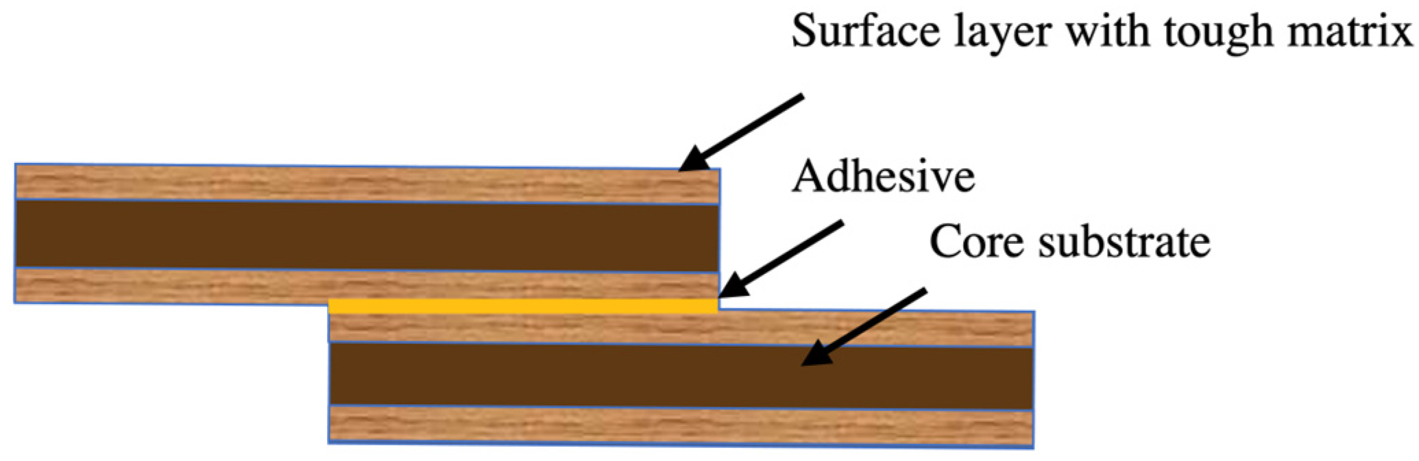
The use of an additional tough layer can significantly decrease stress concentration levels at the overlap ends, resulting in a more uniform stress distribution along the overlap. Additionally, the absorption of adhesive by the wood enhances the strength of the wood in the transverse directions. These factors contribute to the observed improvements in mechanical properties under various loading conditions.
4.1. Implications for Joint Design
From both the static and dynamic analyses, it is evident that substrate modifications play a crucial role in improving the performance of adhesive joints. Toughened joints enhance adhesion strength but also exhibit a higher risk of localized failure due to concentrated stresses, particularly at the overlap edges. Densified joints offer a more uniform stress distribution, reducing the likelihood of early failure and improving the overall durability of the joint. Hybrid joints, which combine the benefits of both toughened outer plies and a densified core, provide the best overall performance by balancing the advantages of both stiffness and toughness. The addition of toughened plies in the hybrid joints significantly mitigates stress concentrations, improving the load transfer across the bondline. The 1 mm thick outer ply offers enhanced stiffness and load distribution but may slightly increase the stress near the edges, suggesting that optimized hybrid designs can further improve wood-based adhesive joints.
Under dynamic conditions, the hybrid joints exhibit higher stress concentrations near the overlap edges and elevated overall stress levels compared to static conditions. This difference arises from the rapid application of the load (6 m/min displacement rate) and the strain rate sensitivity of the materials. At higher loading rates, the adhesive and substrate materials behave viscoelastically, temporarily stiffening and increasing their resistance to deformation. This stiffening effect amplifies stress levels, particularly in critical areas like the overlap edges, where load transfer is most concentrated. For hybrid joints, the stiffness mismatch between the densified core and toughened outer plies exacerbates stress concentrations under dynamic loading. The sharp transition in material properties at the interfaces further concentrates stress, amplifying its level near the edges. This combination of rapid loading, material stiffening, and stiffness mismatch explains the higher stress levels and more pronounced edge concentrations under dynamic conditions.
Under dynamic conditions, the rapid load application reduces the time available for stress to redistribute along the bondline. As a result, stress builds up quickly at localized points, leading to sharper stress concentrations at the overlap edges. In contrast, static loading involves a gradual application of force, allowing the adhesive and substrate to deform more elastically and providing sufficient time for stress redistribution. This results in a more uniform stress distribution and lower edge stress concentrations under static conditions.
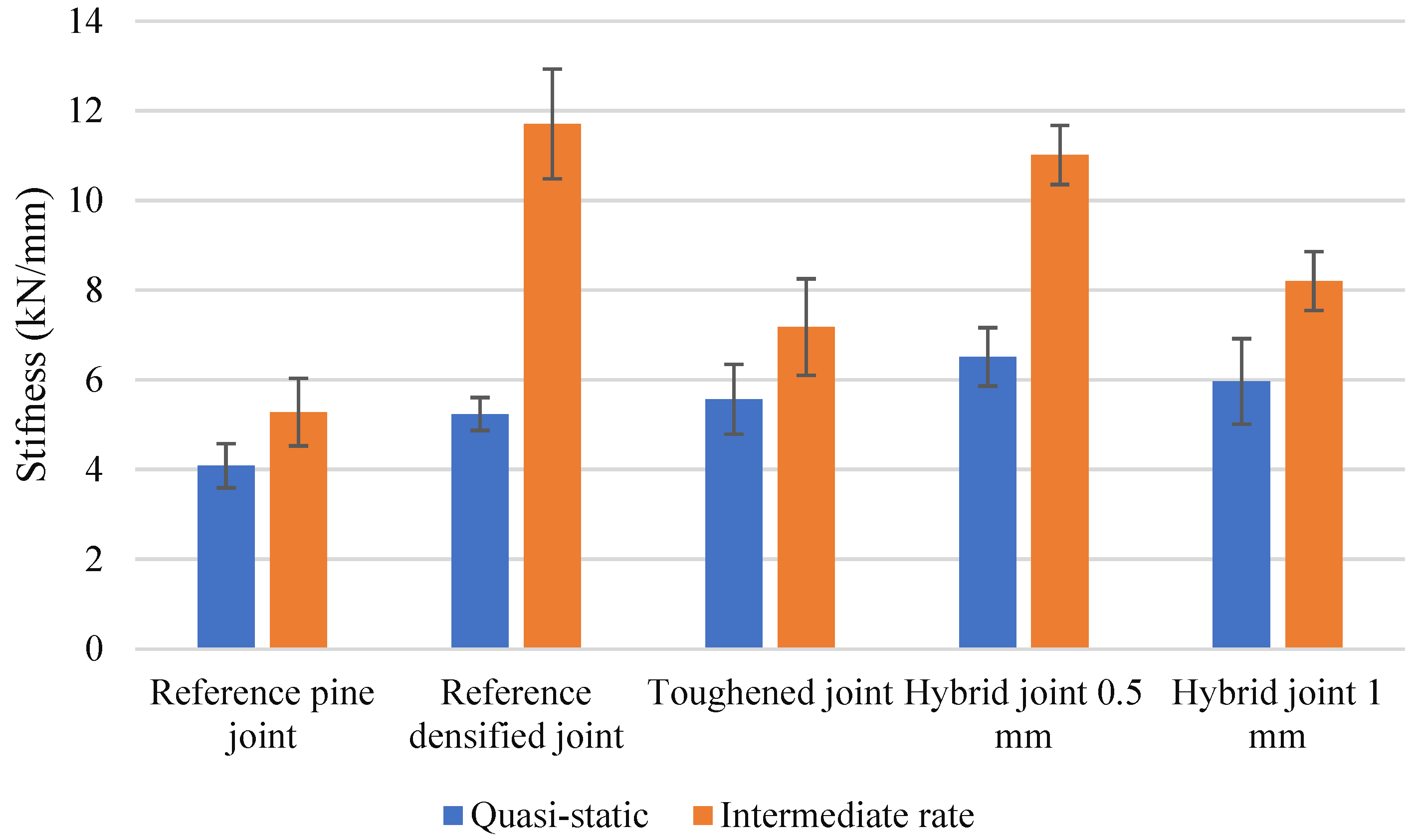
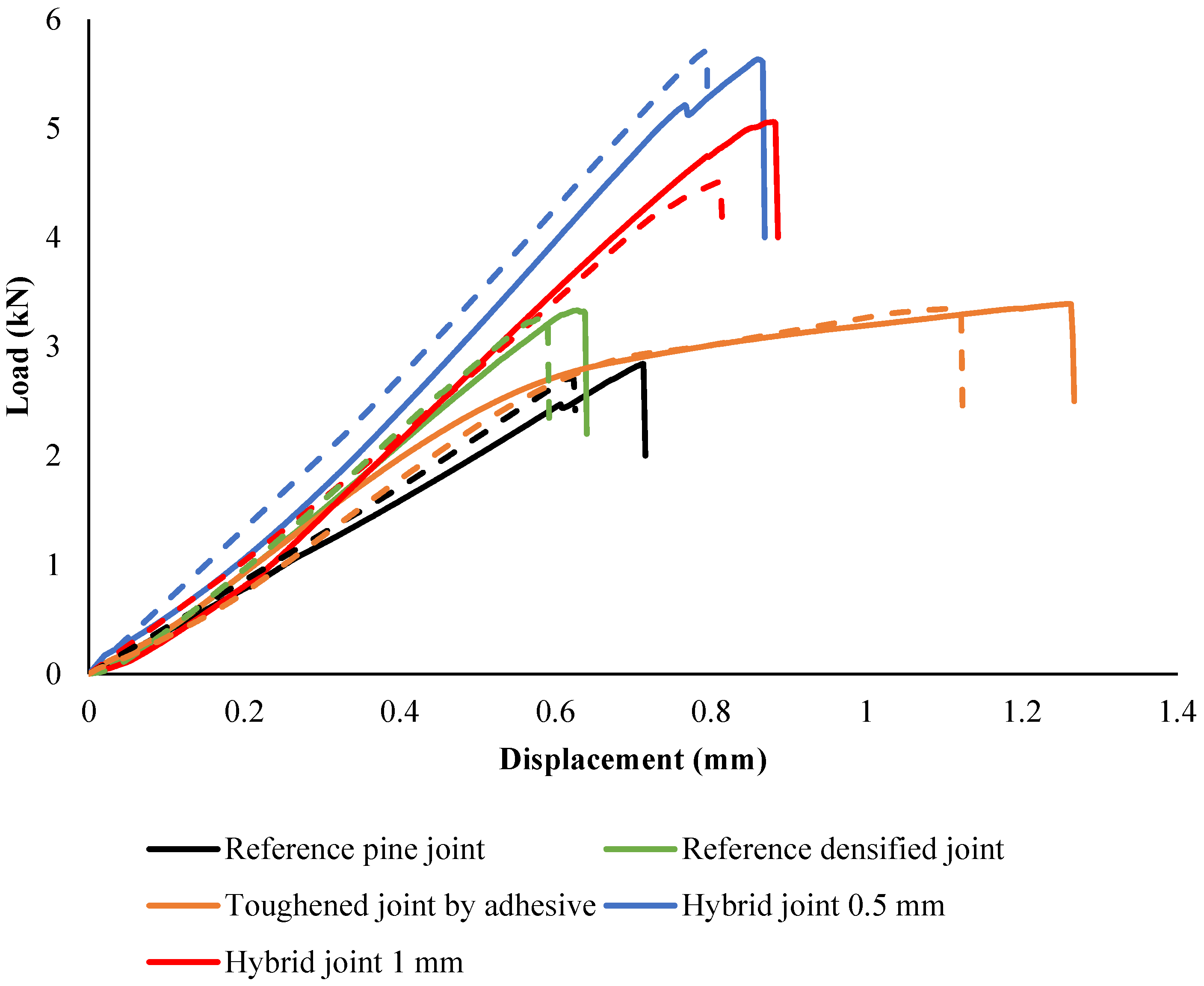
4.2. Quasi-Static
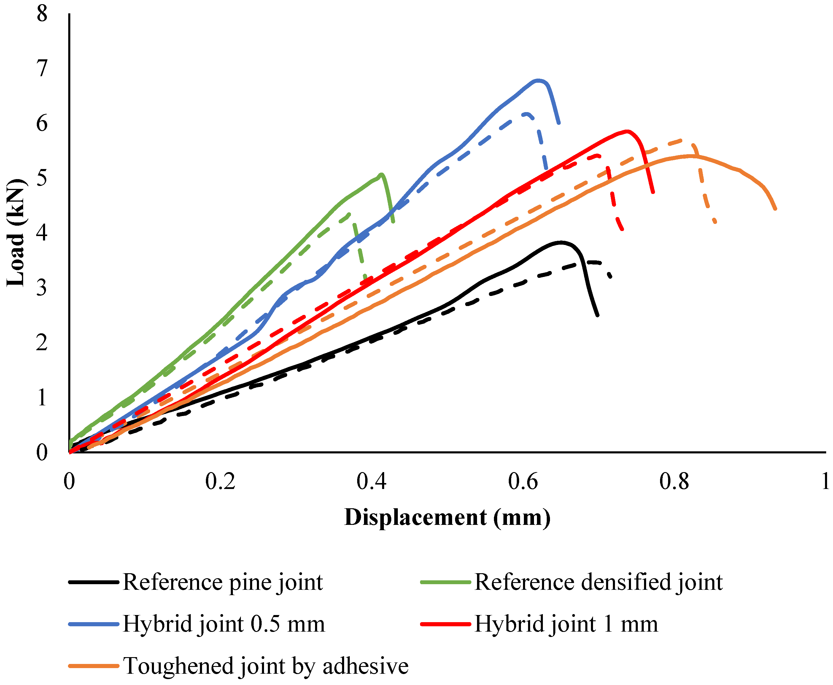
The experimental results shown in
Figure 10 illustrate the load-displacement behavior of the joints under quasi-static conditions. It was found that the toughened joints had a failure load approximately 20% higher than the reference joints. Additionally, the joints exhibited a notable stiffening effect, with stiffness increasing by about 38%. Notably, at the point of failure, the toughened joints displayed plastic deformation within the joint structure when they reached the failure load of the reference joints. Consequently, the displacement at failure increased by around 85%, indicating a higher capacity for energy absorption before failure. This increase in absorbed energy was significant, approximately 170% more than the reference joints. The enhanced energy absorption capability of the toughened joints underscores their improved resilience and ability to dissipate energy effectively.
The nonlinear behavior of the joints results in a much larger area under the curve, leading to a substantial increase in the amount of energy absorbed during testing. Furthermore, it is important to note that the toughening process has a more significant impact on the absorbed energy of the joint than on its failure load, with the absorbed energy increasing by around 230%.
It was observed that the hybrid joints demonstrated the highest failure loads, with the hybrid joint (0.5 mm) reaching a peak load approximately 83% higher than the reference pine joint. The reference densified joint also showed a significant increase in strength, with a failure load approximately 50% higher than the pine joint.
The incorporation of hybrid joints with a toughened layer has been shown to effectively postpone failure, resulting in a substantial enhancement of joint strength by approximately 85% over standard reference joints. This significant increase can be attributed to the utilization of densified wood within the core layer, which bolsters the substrate’s strength, and the application of toughened wood combined with adhesive in the outer plies, which augments peeling strength. This dual approach, leveraging the strengths of both densified and toughened wood, achieves a synergistic effect that substantially elevates the overall structural integrity of the joints. The combination of these materials, each selected for their specific mechanical properties, has been meticulously engineered to work in concert, resulting in a composite material that not only meets but exceeds performance expectations in demanding applications. The displacement at failure exhibited notable differences among the joints. The joint toughened by adhesive showed a 37% increase in displacement compared to the reference pine joint, indicating enhanced flexibility. In comparison, the hybrid joints demonstrated similar or slightly greater displacement, with the 0.5 mm hybrid joint showing a displacement increase of approximately 38%, reflecting a greater capacity for energy absorption before failure. The failure modes of the joints were primarily brittle, with the exception of the reference densified joint, which exhibited a more gradual reduction in load post-peak, indicating a less brittle response. The stiffening effect observed in the densified joint reduced displacement by 25%, reflecting a trade-off between strength and flexibility. Of particular interest is the energy absorption capability of the hybrid joints. Due to the larger areas underneath their load–displacement curves, the hybrid joint (0.5 mm) absorbed approximately 83% more energy compared to the reference pine joint. This highlights the effectiveness of hybridization in enhancing both strength and energy dissipation capacity.
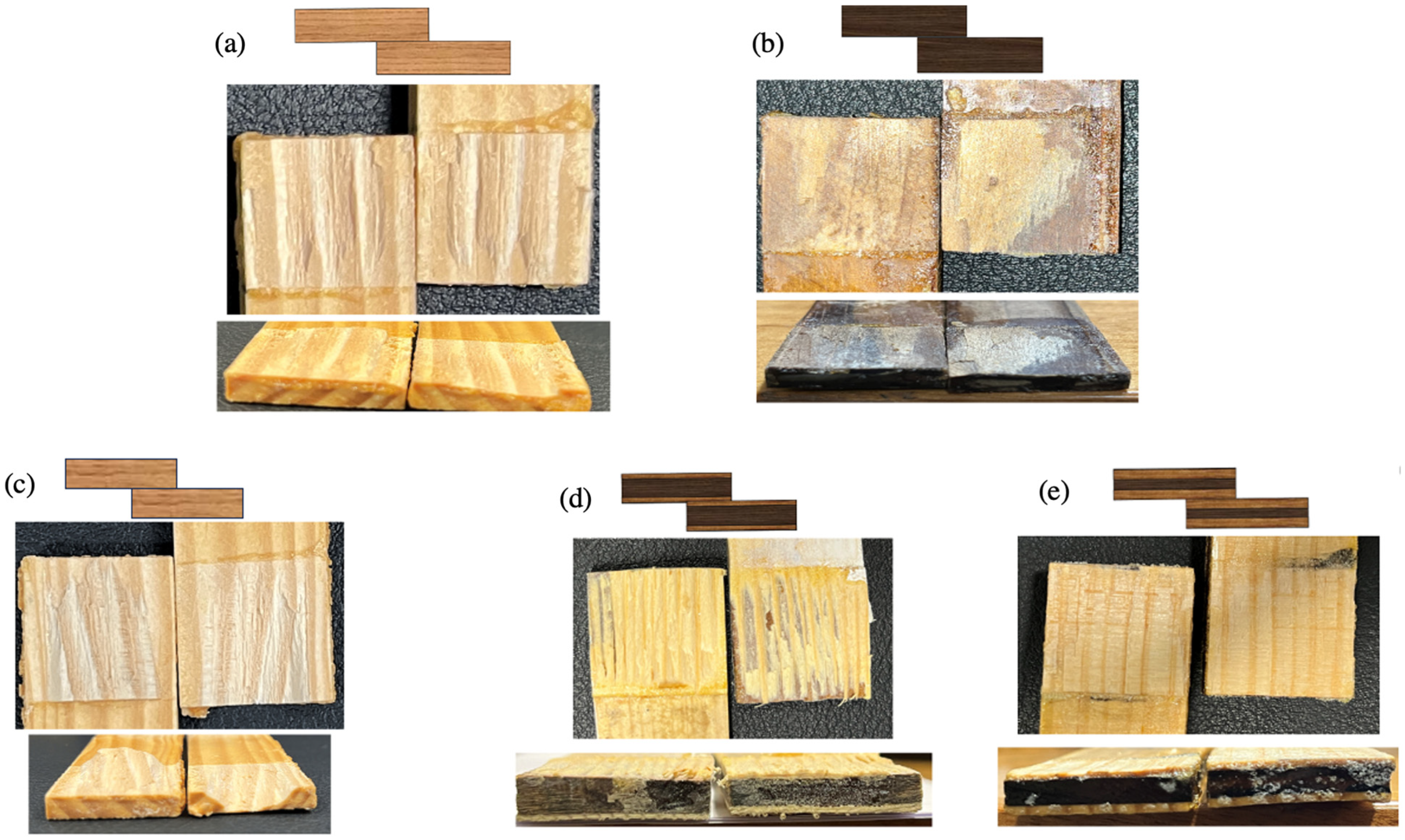
4.3. Fracture Surfaces
Analyzing fracture surfaces is essential for identifying failure causes in bonded joints. Fracture surfaces often exhibit micro and macro cracks. Examining crack initiation and propagation reveals key details about loading conditions and failure outcomes. In brittle materials, cracks typically initiate failure due to the absence of a plastic zone at the crack front, leading to rapid propagation and sudden failure.
Figure 11 shows digital images of the fracture surfaces analyzed to understand joint behavior under quasi-static loads. The analysis revealed that wood delamination was the main failure mode in both toughened and reference joints, indicating effective adhesive curing and good adhesion. However, a significant difference was noted in the toughened joints compared with the reference joints. In the reference joints, delamination occurred at a shallow depth within the wood, concentrating failure in the surface layers. Conversely, the toughened joints exhibited a different failure pattern, with failure mainly occurring in the non-toughened wood region. This observation is significant because the non-toughened core bore most of the failure, while the outer layers, which had better adhesion due to adhesive penetration, were more resilient. This behavior increased the failure load of the toughened joints. The key to this phenomenon is the stress distribution along the overlap, where stress concentration at the ends approached the wood’s failure threshold, causing the observed change in failure mode.
Figure 11 illustrates that in densified wood joints, substrate delamination was minimal due to the low peel strength of the densified wood. The substrate delaminated at the thickness with the highest stress level, close to the bonding line.
Figure 11 also highlights the different fracture behaviors of the joints. In the toughened joint, the crack path was more complex and deeper, requiring more energy to reach failure. In contrast, the reference joint had a relatively uniform delamination path, with the crack mainly propagating horizontally along the overlap. However, in the toughened joint, the crack followed a more intricate path, changing direction vertically and interacting with different grain orientations, even propagating vertically through the wood’s thickness. The delamination thickness in both hybrid joints was nearly identical; however, the joint with the 0.5 mm toughened layer displayed a more intricate fracture mechanism, which resulted in greater energy absorption during failure. This complexity can be attributed to the way the crack propagated through the material. Instead of following a straightforward path, the crack traveled between different wood grains and fibers, indicating a more irregular failure process. In some regions, the crack diverted or “kinked” toward the interface between the toughened layer and the densified wood, where the two materials were bonded together using the bio-adhesive.
This crack redirection suggests that the interaction between the toughened layer and the densified wood, facilitated by the bio-adhesive, played a significant role in resisting crack propagation. The presence of the toughened layer not only added complexity to the fracture process but also distributed the stresses across different planes, requiring more energy for the crack to progress. This intricate interaction between the wood fibers, toughened layer, and bio-adhesive likely contributed to the joint’s enhanced ability to absorb energy, making the fracture mechanism in the 0.5 mm hybrid joint more resistant to sudden failure compared to simpler joint configurations.
4.4. Intermediate Rate
4.4.1. Load-Displacement Behavior
Figure 12 illustrates the load-displacement behavior of the reference, toughened, densified, and hybrid joints under intermediate-rate conditions. Both experimental and numerical results reveal distinct differences in performance across configurations, highlighting the effectiveness of material modifications.
Experimental data indicate that toughened joints exhibit a 45% increase in failure load compared to reference joints, with a peak load of approximately 5.4 kN at 0.65 mm displacement. Numerical simulations corroborate this trend, accurately capturing the delayed damage initiation and higher energy absorption capabilities of toughened joints. These enhancements stem from the reinforcement provided by the toughening process, which improves the wood matrix’s resistance to delamination and adhesive failure. However, under intermediate-speed loading, both experimental and numerical results reveal a brittle failure mode characterized by abrupt post-peak stiffness degradation.
Densified joints perform moderately better than reference joints, achieving a peak load of 4.8 kN at 0.33 mm displacement. The densification increases stiffness and load-carrying capacity but does not enhance energy absorption to the same extent as toughened joints. Both experimental and numerical data confirm that densified joints exhibit a more gradual decline in stiffness after peak load, reducing the risk of sudden failure but lacking the toughness of toughened configurations.
Hybrid joints, which combine densified cores with toughened outer layers, offer a balance of stiffness and toughness. Experimental results show the 1 mm hybrid joint achieving a peak load of 5.7 kN at 0.6 mm displacement, while the 0.5 mm hybrid joint reaches 6.5 kN at 0.55 mm displacement. Numerical models align closely with these findings, reflecting the synergy between the core and outer layers that improves damage resistance and energy absorption. Hybrid joints exhibit more gradual stiffness degradation compared to fully toughened joints, making them a versatile choice for applications requiring a balance of load capacity and durability.
In contrast, reference joints display the lowest performance, with a peak load of approximately 3.7 kN at 0.45 mm displacement. Experimental and numerical results consistently reveal early damage initiation, primarily due to fiber tear-out, leading to rapid post-peak failure. This behavior underscores the limitations of untreated wood substrates under dynamic conditions.
4.4.2. Damage Mechanisms and Failure Modes
The fracture surfaces, depicted in
Figure 13, highlight the differences in damage mechanisms across joint configurations. Reference joints show minor delamination at the substrate interface, resulting in early failure. Conversely, toughened joints exhibit extensive delamination, attributed to improved peel strength and viscoelastic effects of lignin in the wood substrate. Numerical analysis supports these observations (
Figure 14), showing delayed damage initiation in toughened joints, with cracks propagating through the substrate at higher loads.
Hybrid joints demonstrate a mix of delamination and fiber breakage. As loading rates increase, hybrid joints show deeper substrate delamination compared to reference and densified joints. The presence of toughened outer layers enhances peel strength, redirecting crack propagation through weaker transverse plies. This combination of behaviors, observed experimentally and predicted numerically, explains the hybrid joints’ improved performance under intermediate rates.
Densified joints show localized damage with less extensive delamination. Experimental and numerical analyses agree that densification reduces premature failure by creating a more uniform stress distribution across the bondline. However, this configuration lacks the toughness required to prevent failure at higher loads, as observed in the other configurations.
4.5. Strain Rate Sensitivity and Material Behavior
Under intermediate loading rates, viscoelastic materials like wood and bio-based adhesives exhibit increased stiffness but reduced ductility. Experimental data and numerical predictions consistently demonstrate that toughened joints withstand higher loads before damage initiation, with delayed microcracking and adhesive failure. Hybrid joints perform similarly, benefiting from the combined effects of toughened and densified components. Reference joints, on the other hand, show lower thresholds for damage initiation, with rapid crack propagation leading to early failure.
Delamination emerges as the dominant failure mode across all joint configurations. Toughened and hybrid joints resist delamination at higher loads, delaying the final failure. Reference joints, however, exhibit early delamination, resulting in a reduced load-carrying capacity. Numerical models accurately replicate these trends, validating the computational approach.


 ,
, 


