
Correlation of the Thermal Conductivity and Mechanical Properties in Hybrid Filler Systems of Thermosets


Abstract
1. Introduction
1.1. Application Fields and Possible Extensions
1.2. Mechanisms of Thermal Conductivity of Thermoset-Based Compounds
1.3. Influencing Factors on the Thermal Conductivity of Filled Thermosets
1.4. Aim of the Paper
2. Materials and Methods
2.1. Materials
2.2. Fabrication of the Test Specimens
2.3. Characterization
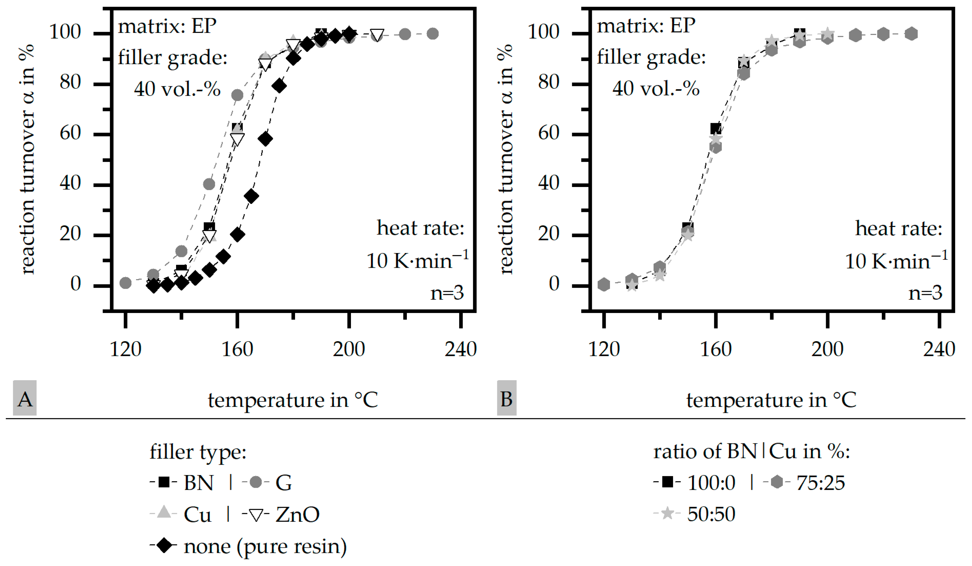
2.3.1. Differential Scanning Calorimetry (DSC) According to DIN EN ISO 11357
2.3.2. Density ρ
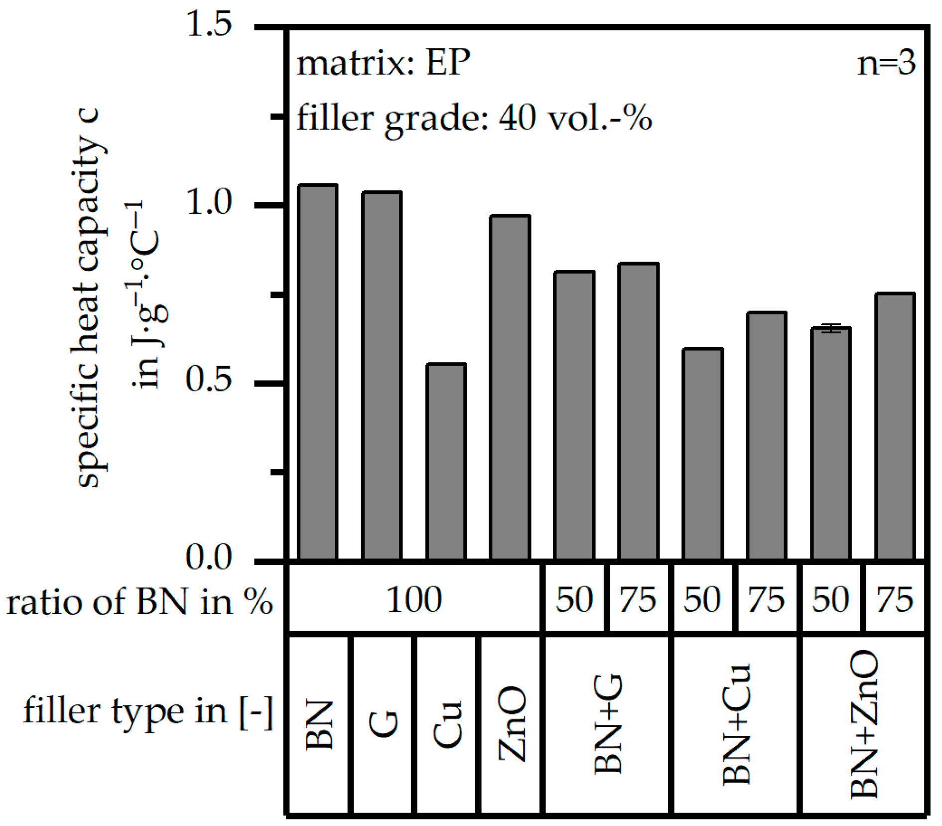
2.3.3. Specific Heat Capacity c
2.3.4. Thermal Diffusivity a According to DIN EN ISO 22007
2.3.5. Thermal Conductivity λ According to DIN EN ISO 22007
2.3.6. Mechanical Properties According to DIN EN ISO 527
2.3.7. Filler Distribution
3. Results and Discussion
3.1. Results of Differential Scanning Calorimetry (DSC) According to DIN EN ISO 11357
3.2. Results of Density ρ
3.3. Results of Specific Heat Capacity c
3.4. Results of Thermal Conductivity λ According to DIN EN ISO 22007
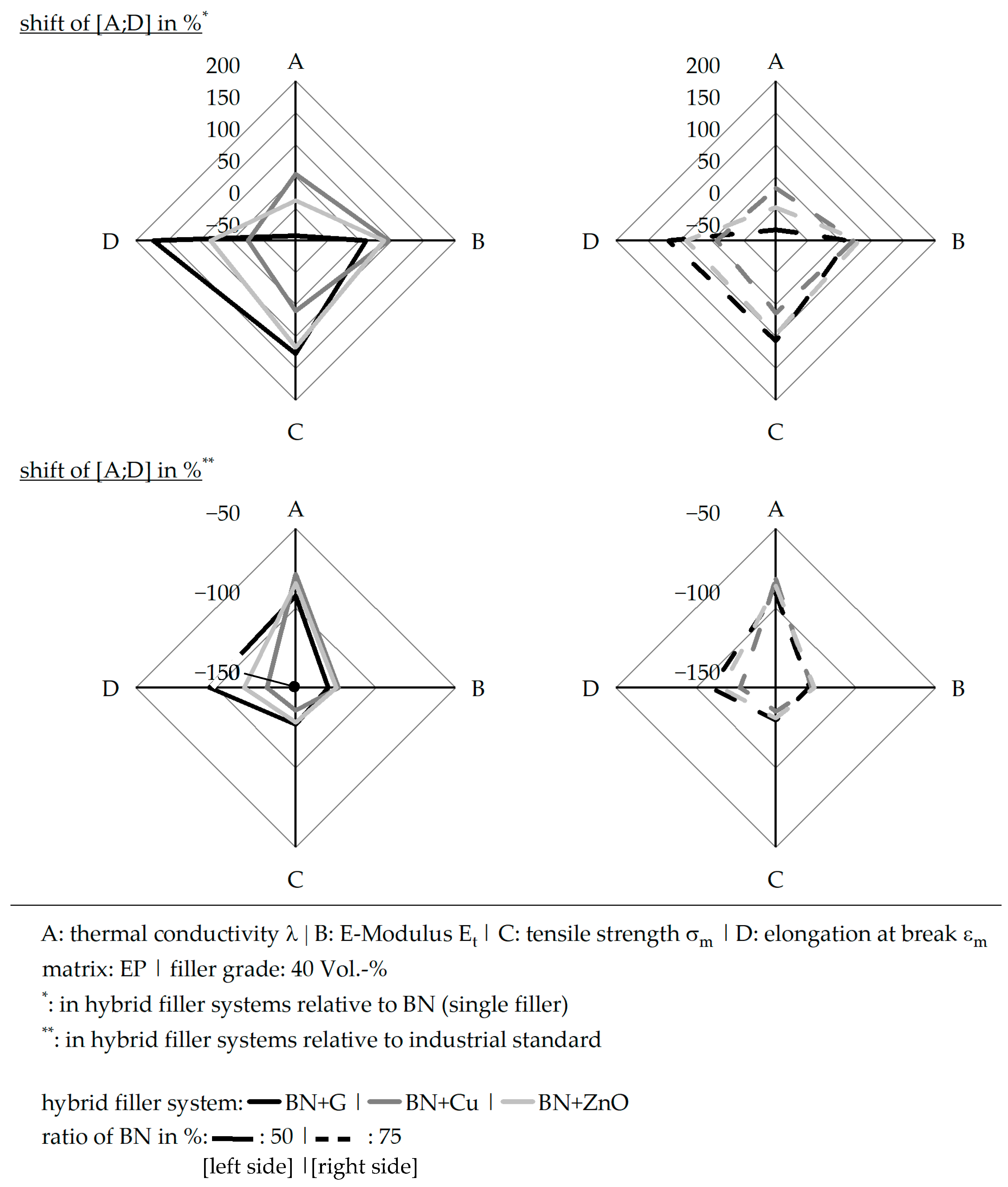
3.5. Results of Mechanical Properties According to DIN EN ISO 527
3.6. Results of Filler Distribution
4. Discussion
5. Conclusions
Author Contributions
Funding
Institutional Review Board Statement
Data Availability Statement
Conflicts of Interest
References
- Koch, I. Vergleich Si und SiC Halbleiter; Jahresbericht: Brauchschweig, Germany, 2007. [Google Scholar]
- SiC-Halbleiter: Schlüsseltechnologie zur Effizienten und Nachhaltigen Elektronik. 2024. Available online: https://www.siconnex.com/?page_id=6360 (accessed on 8 July 2025).
- Baur, E.; Drummer, D.; Osswald, T.; Rudolph, N. Saechtling: Kunststoff-Handbuch, 32nd ed.; Carl Hanser Verlag: Munich, Germany, 2022. [Google Scholar]
- Osswald, T.; Menges, G. Material Chience of Polymers for Engineers, 3rd ed.; Hanser: München, Germany, 2012. [Google Scholar]
- Ehrenstein, G.W.; Drummer, D. (Eds.) Hochgefüllte Kunststoffe mit Definierten Magnetischen, Thermischen und Elektrischen Eigenschaften; Springer VDI: Düsseldorf, Germany, 2002. [Google Scholar]
- Übler, W. Erhöhung der Thermischen Leitfähigkeit Elektrisch Isolierender Polymerwerkstoffe. Ph.D. Thesis, Friedrich-Alexander University, Erlangen, Germany, 2004. [Google Scholar]
- Cai, Z. Simulation of the Manufacture of Closed Shape Composite Structures. Ph.D. Thesis, Massachusetts Institute of Technology, Cambridge, MA, USA, 1990. [Google Scholar]
- Xu, Y.; Chung, D.; Mroz, C. Thermally conducting aluminum nitride polymer-matrix composites. Compos. Part A Appl. Sci. Manuf. 2001, 32, 1749–1757. [Google Scholar] [CrossRef]
- Yung, K.C.; Liem, H. Enhanced thermal conductiity of boron nitride epoxy-matrix composite through multi-modal particle size mixing. J. Appl. Polym. Sci. 2007, 106, 3587–3591. [Google Scholar] [CrossRef]
- Zhou, M.-H.; Yin, G.-Z.; Prolongo, S.G. Review of thermal conductivity on epoxy thermosets and composites: Mechanism, parameters, and filler influences. Adv. Ind. Eng. Polym. Res. 2024, 7, 295–308. [Google Scholar] [CrossRef]
- Sun, Z.; Li, J.; Yu, M.; Kathaperumal, M.; Wong, C. A review of the thermal conductivity of silver-epoxy nanocomposites as encapsulation material for packaging applications. Chem. Eng. J. 2022, 446, 137319. [Google Scholar] [CrossRef]
- Fan, J.; Zhang, S.; Zhao, G.; Fu, Q. Constructing fibrillated skeleton with highly aligned boron nirtide nanosheets confined in alumina fiber via electroispinning an dsintering for thermally conductive composite. Compos. Part A Appl. Sci. Manuf. 2021, 143, 106282. [Google Scholar] [CrossRef]
- Shen, X.; Wang, Z.; Wu, Y.; Liu, X.; Kim, J. Effect of functionalization on thermal conductivies of graphene/epoxy composites. Carbon 2016, 108, 412–422. [Google Scholar] [CrossRef]
- Pan, D.A.; Yang, G.; Abo-Dief, H.M.; Dong, J.; Su, F.; Liu, C.; Li, Y.; Xu, B.B.; Murugadoss, V.; Naik, N.; et al. Vertically aligned silicon carbide nanowires/boron nitride cellulose aerogel networks enhanced thermal conductivity and electromagnetic absorbing of epoxy composites. Nano-Micro Lett. 2022, 14, 118. [Google Scholar] [CrossRef] [PubMed]
- Feng, Y.; Han, G.; Wang, B.; Zhou, X.; Ma, J.; Ye, Y.; Liu, C.; Xie, X. Multiple synergistic effects of graphene-based hybrid and hexagonal boron nitride in enhancing thermal cundzuctivity and flame retardancy of epoxy. Chem. Eng. J. 2020, 379, 122402. [Google Scholar] [CrossRef]
- Yang, X.; Zhu, J.; Yang, D.; Yang, J.; Guo, Y.; Zhong, J.; Kong, J.; Gu, J. High-effeciency improvement of thermal conductivity for epoxy omposites from synthesized liquid crystal epoxy followed by doping BN fillers. Compos. Part B Eng. 2020, 185, 107784. [Google Scholar] [CrossRef]
- Beyer, M. Epoxidharze in der Elektrotechnik: Grundlagen, Verabeitunsganlagen Anwendungen und neue Erkenntnisse; Grafenau/Württ. Expert-Verlag: Böblingen, Germany, 1983. [Google Scholar]
- Johannaber, F.; Michaeli, W. Handbuch Spritzgießen, 2nd ed.; Carl Hanser Verlag: München, Germany, 2004. [Google Scholar]
- Zhao, Y.; Zhai, Z.; Drummer, D. Thermal conductivity of Aluminosilicate- and Aluminum Oxide-filled thermosets for injection molding: Effect of filler content, filler size and filer geometry. Polymers 2018, 10, 457. [Google Scholar] [CrossRef] [PubMed]
- Jasmee, S.; Omar, G.; Othaman, S.S.C.; Masripan, N.A.; Hamid, H.A. Interface thermal resistance and thermal conductivity of polymer composites at different types, shapes, and sizes of fillers: A review. Polym. Compos. 2021, 42, 2629–2652. [Google Scholar] [CrossRef]
- Liu, C.; Chen, M.; Zhou, D.; Wu, D.; Yu, W. Effect of filler shape on the thermal conductivity of thermal functional composites. J. Nanomater. 2017, 2017, 6375135. [Google Scholar] [CrossRef]
- Mahanta, N.K.; Loos, M.R.; Zlocozower, I.M.; Abramson, A.R. Graphite–graphene hybrid filler system for high thermal conductivity of epoxy composites. J. Mater. Res. 2015, 30, 959–966. [Google Scholar] [CrossRef]
- Cassing, W.; Kuntze, K.; Ross, G. Dauermagnete: Mess-und Magnetisierungstechnik, 3rd ed.; Expert-Verlag: Renningen, Germany, 2018. [Google Scholar]
- Chen, L.; Sun, Y.-Y.; Lin, J.; Du, X.-Z.; Wei, G.-S.; He, S.-J.; Nazarenko, S. Modeling and analysis of synergistic effect in thermal conductivity enhancement of polymer composites with hybrid filler. Int. J. Heat Mass Transf. 2015, 81, 457–464. [Google Scholar] [CrossRef]
- Yu, W.; Xie, H.; Yin, L.; Zhao, J.; Xia, L.; Chen, L. Exceptionally high thermal conductivity of thermal grease: Synergistic effects of graphene and alumina. Int. J. Therm. Sci. 2015, 91, 76–82. [Google Scholar] [CrossRef]
- DIN EN ISO 11357-1:2017-02; Kunststoffe-Dynamische Differenz Thermoanalyse (DSC): Teil 1: Allgemeine Grundlagen. Deutsches Institut für Normung e. V. Beuth Verlag GmbH: Berlin, Germany, 2017. Available online: https://www.dinmedia.de/de/norm/din-en-iso-11357-1/264864949 (accessed on 21 February 2023).
- Rösel, U.; Drummer, D. Influence of Different Filler Systems on the Thermal Conductivity and Mechanical Properties of Thermosets. Polymers 2024, 16, 2917. [Google Scholar] [CrossRef] [PubMed]
- DIN EN ISO 22007-1:2024-07; Kunststoffe-Bestimmung der Wärmeleitfähigkeit und der Temperaturleitfähigkeit: Teil 1: Allgemeine Grundlagen. Deutsches Institut für Normung e. V.; Beuth Verlag GmbH: Berlin, Germany, 2018. Available online: https://www.dinmedia.de/de/norm/din-en-iso-22007-1/379040602 (accessed on 21 February 2023).
- DIN EN ISO 20753:2024-03-01; Kunststoffe-Probekörper. Deutsches Institut für Normung e. V.; Beuth Verlag GmbH: Berlin, Germany, 2024. Available online: https://www.dinmedia.de/de/norm/oenorm-en-iso-20753/378450808 (accessed on 21 February 2023).
- DIN EN ISO 527-1:2019-12; Kunststoffe-Bestimmung der Zugeigenschaften: Teil 1: Allgemeine Grundsätze. Deutsches Institut für Normung e. V.; Beuth Verlag GmbH: Berlin, Germany, 2019. Available online: https://www.dinmedia.de/de/norm/din-en-iso-527-1/306958894 (accessed on 21 February 2023).


| Matrix Material | Density δ in g∙cm−3 | Heat Capacity c in J∙g−1∙°C−1 | Thermal Conductivity λ in W∙m−1∙K−1 |
|---|---|---|---|
| epoxy resin (EP) | 1.2250 | 1.616 | 0.4–0.6 |
| Filler System | Density δ in g∙cm−3 | Particle Size [n | v] in µm | Heat Capacity c in J∙g−1∙°C−1 | Thermal Conductivity λ in W∙m−1∙K−1 |
|---|---|---|---|---|
| boron nitride (BN) | 2.27 | 4.77 | 24.34 | 0.794 | 15 ⊥; 400 ‖ |
| glass (G) | 2.48 | 4.70 | 18.53 | 0.808 | 1 |
| copper (Cu) | 8.65 | 18.19 | 41.60 | 0.394 | 400 |
| zinc oxide (ZnO) | 5.65 | 1.64 | 3.30 | 0.505 | 30 |
| Filler System | BN | G | Cu | ZnO |
|---|---|---|---|---|
| particle geometry |  | 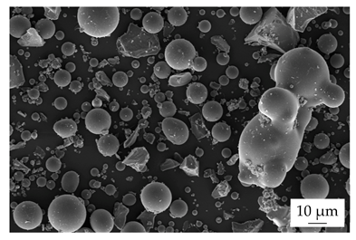 | 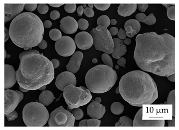 | 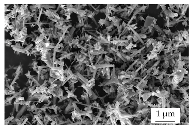 |
| platelet | sphere | sphere | star |
| Matrix Material | EP | EP | EP | EP | EP | EP | EP |
|---|---|---|---|---|---|---|---|
| filler system | BN | G | Cu | ZnO | BN + G | BN + Cu | BN + ZnO |
| filler grade | 40 vol.-% | ||||||
| mixing proportion | - | 50 | 50 || 75| 25 | |||||
| process parameter | |||||||
| mass temperature Tm in °C [feeding | noozle] | 55 | 95 | 55 | 85 | 65 | 85 | 65 | 85 | 55 | 85 | 55 | 85 | 55 | 85 |
| mold temperature TWZ in °C | 160 | 195 | 180 | 180 | 190 | 190 | 190 |
| heating time th in s | 85 | 75 | 75 | 75 | 85 | 85 | 85 |
| injection speed vin in mm∙s−1 | 15 | 15 | 15 | 15 | 15 | 15 | 15 |
Disclaimer/Publisher’s Note: The statements, opinions and data contained in all publications are solely those of the individual author(s) and contributor(s) and not of MDPI and/or the editor(s). MDPI and/or the editor(s) disclaim responsibility for any injury to people or property resulting from any ideas, methods, instructions or products referred to in the content. |
© 2025 by the authors. Licensee MDPI, Basel, Switzerland. This article is an open access article distributed under the terms and conditions of the Creative Commons Attribution (CC BY) license (https://creativecommons.org/licenses/by/4.0/).
Share and Cite
Rösel, U.; Drummer, D. Correlation of the Thermal Conductivity and Mechanical Properties in Hybrid Filler Systems of Thermosets. Polymers 2025, 17, 1924. https://doi.org/10.3390/polym17141924
Rösel U, Drummer D. Correlation of the Thermal Conductivity and Mechanical Properties in Hybrid Filler Systems of Thermosets. Polymers. 2025; 17(14):1924. https://doi.org/10.3390/polym17141924
Chicago/Turabian StyleRösel, Uta, and Dietmar Drummer. 2025. "Correlation of the Thermal Conductivity and Mechanical Properties in Hybrid Filler Systems of Thermosets" Polymers 17, no. 14: 1924. https://doi.org/10.3390/polym17141924
APA StyleRösel, U., & Drummer, D. (2025). Correlation of the Thermal Conductivity and Mechanical Properties in Hybrid Filler Systems of Thermosets. Polymers, 17(14), 1924. https://doi.org/10.3390/polym17141924