Modelling and Optimisation of FDM-Printed Short Carbon Fibre-Reinforced Nylon Using CCF and RSM
Abstract
1. Introduction
2. Experimental Procedures
2.1. Material and Printing Device
2.2. Mechanical Tests and Observation of Fracture Surface
2.3. Experiment Design
3. Results and Discussions
3.1. Effect of Process Parameters on the Flexural Strength (Y1)
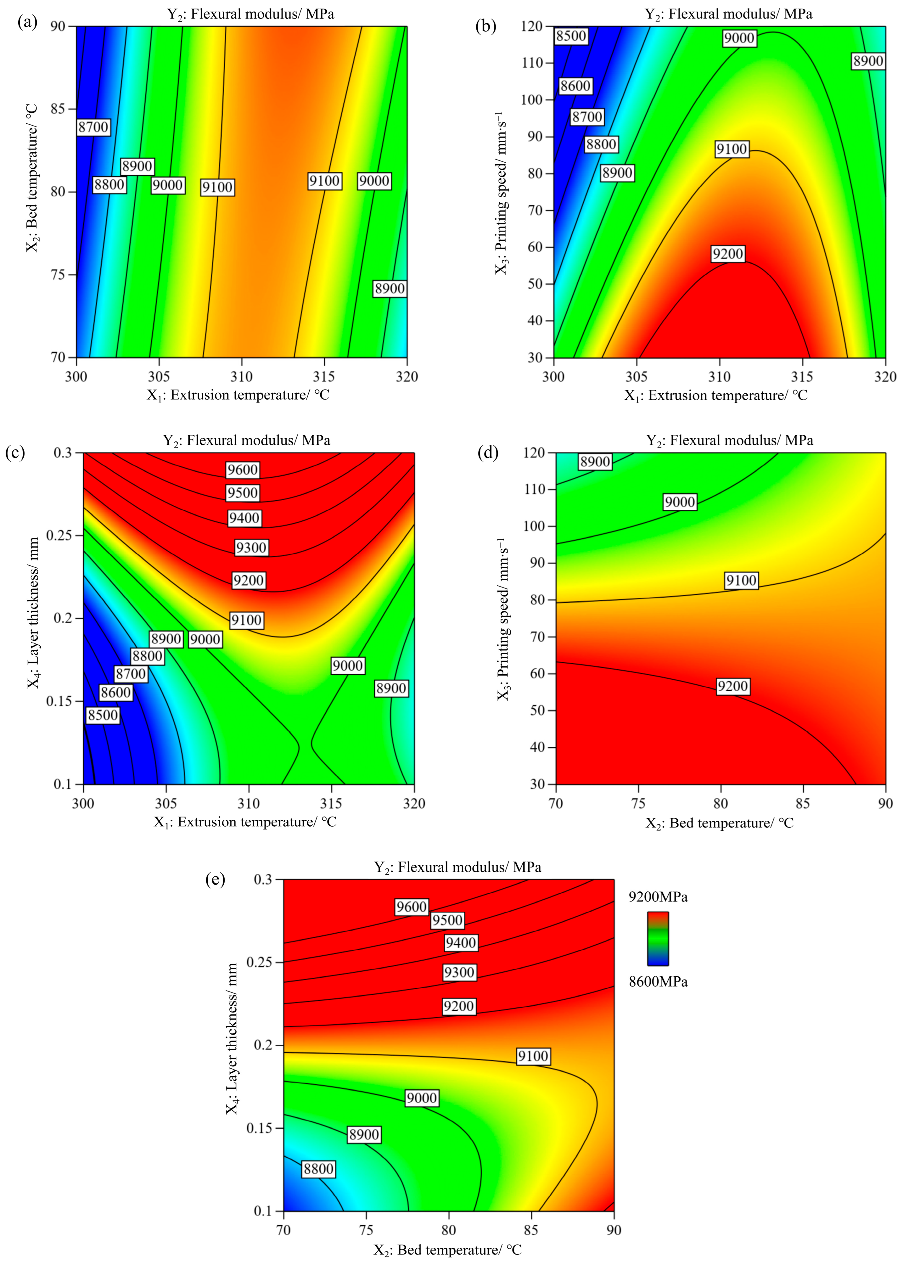
3.2. Effect of Process Parameters on Flexural Modulus (Y2)
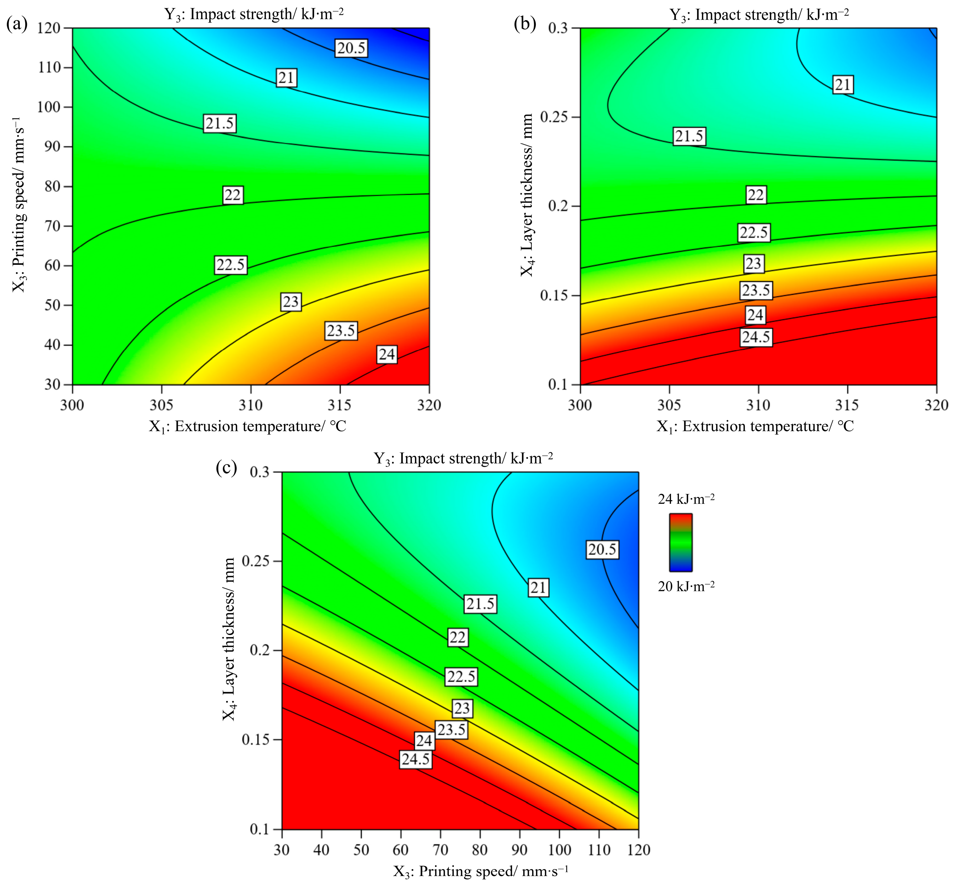
3.3. Effect of Process Parameters on Impact Strength (Y3)
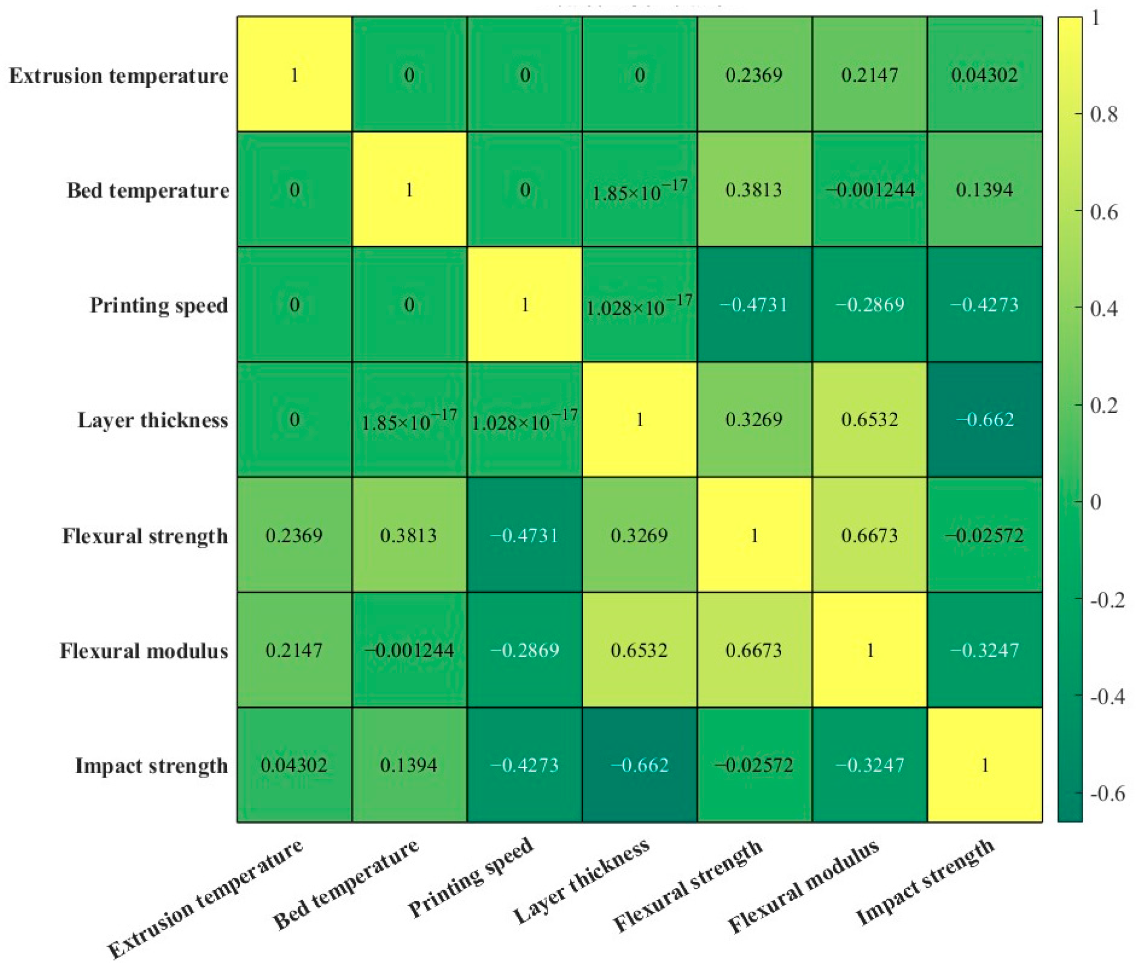
3.4. Correlation Analysis Between the Process Parameters and Mechanical Properties
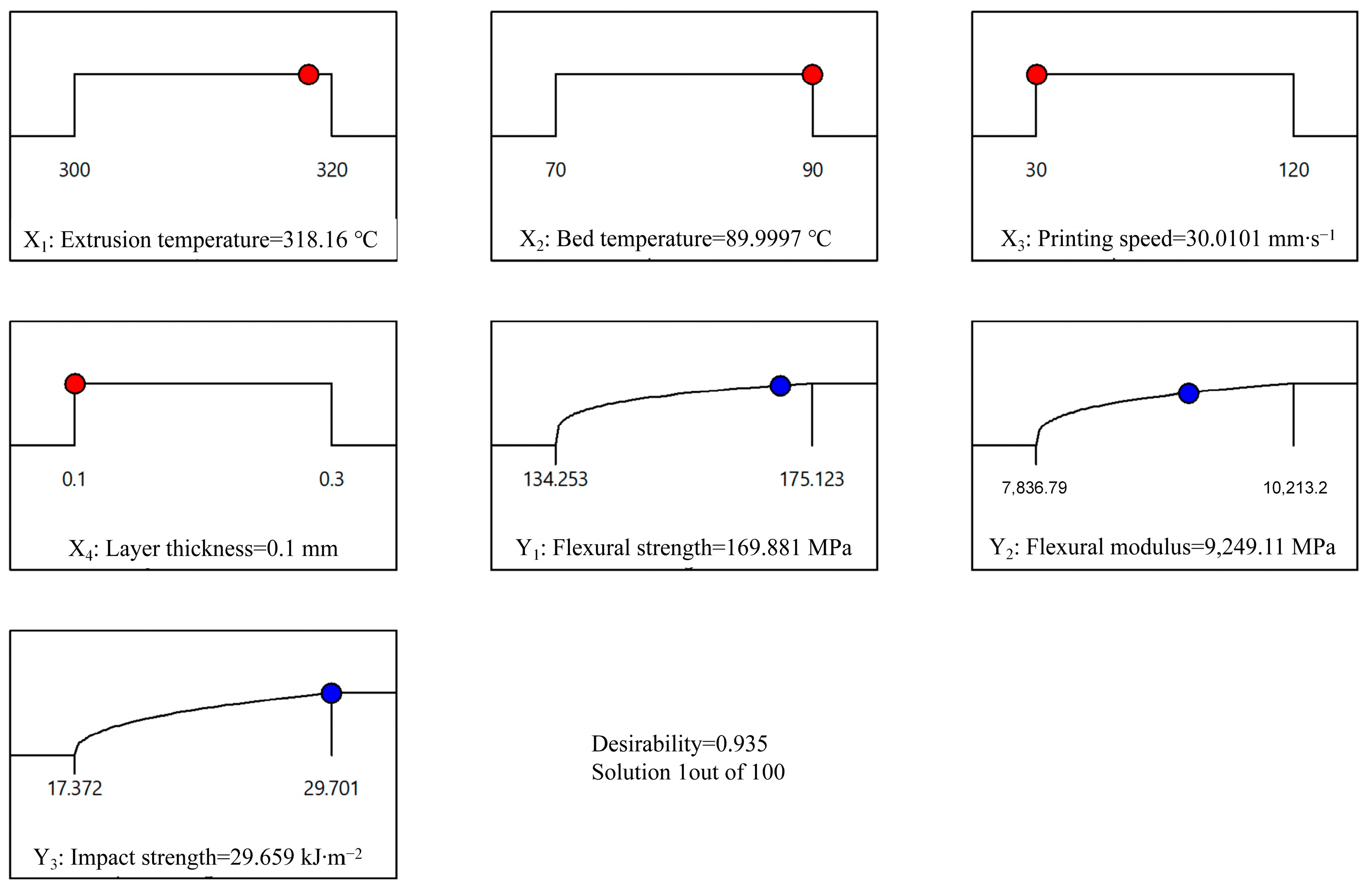
3.5. Multi-Response Optimisation and Validation
4. Conclusions
- (1)
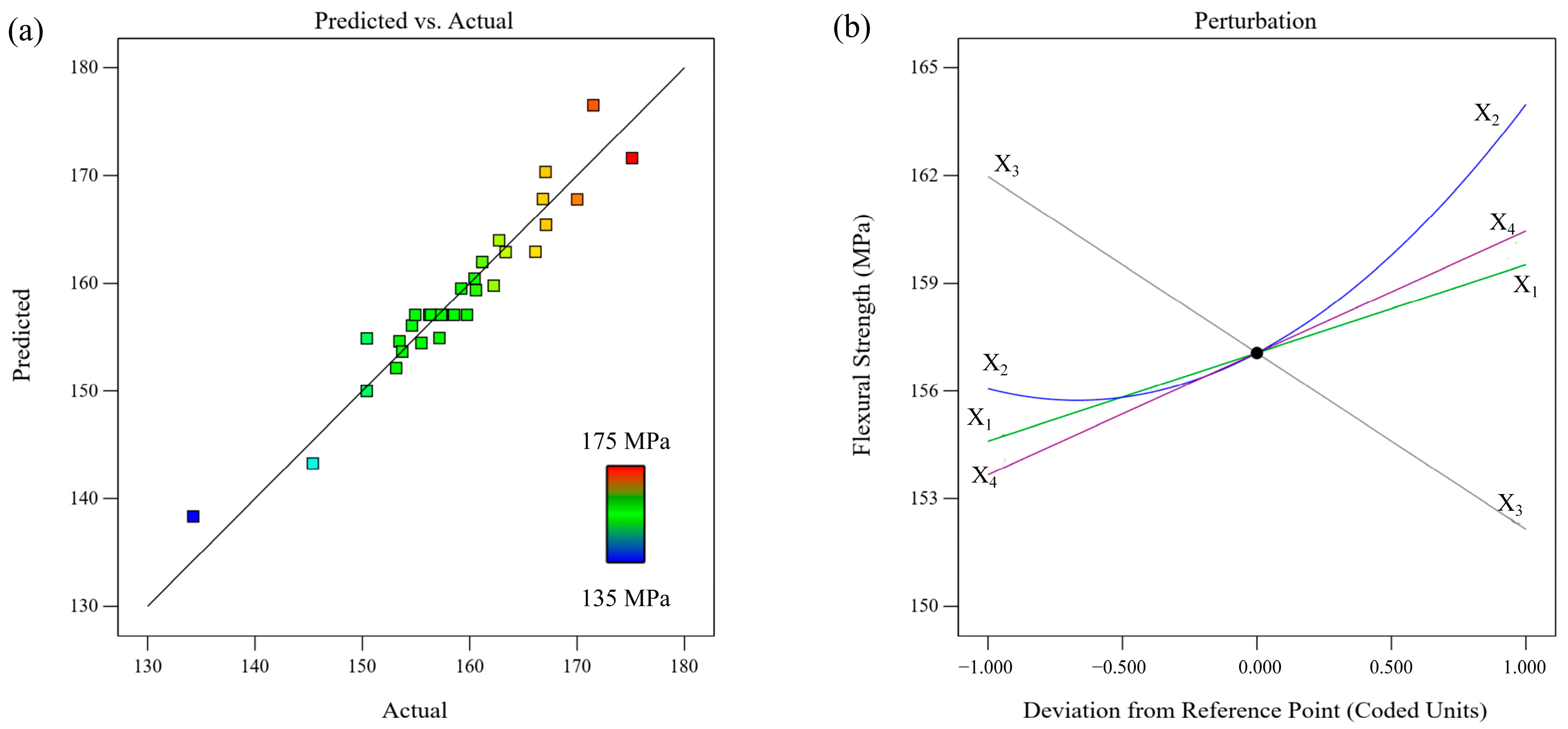
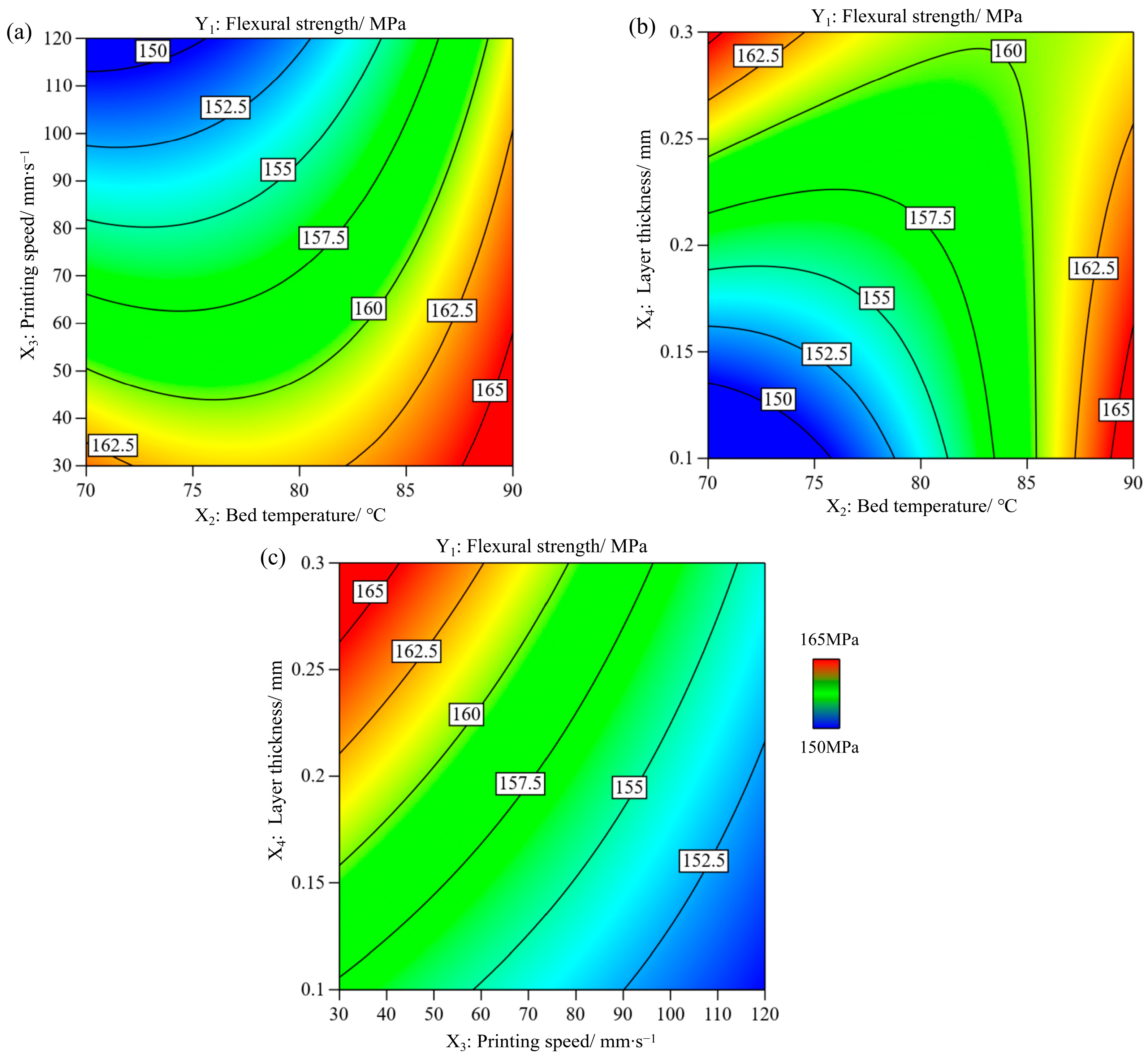
- The flexural strength of the FDM-printed parts varied in the range of 134.253–175.123 MPa under the studied parameters. All four parameters had a significant influence on the flexural strength, and the order of the degree of influence was X3 (printing speed) > X2 (bed temperature) > X4 (layer thickness) > X1 (extrusion temperature).
- (2)
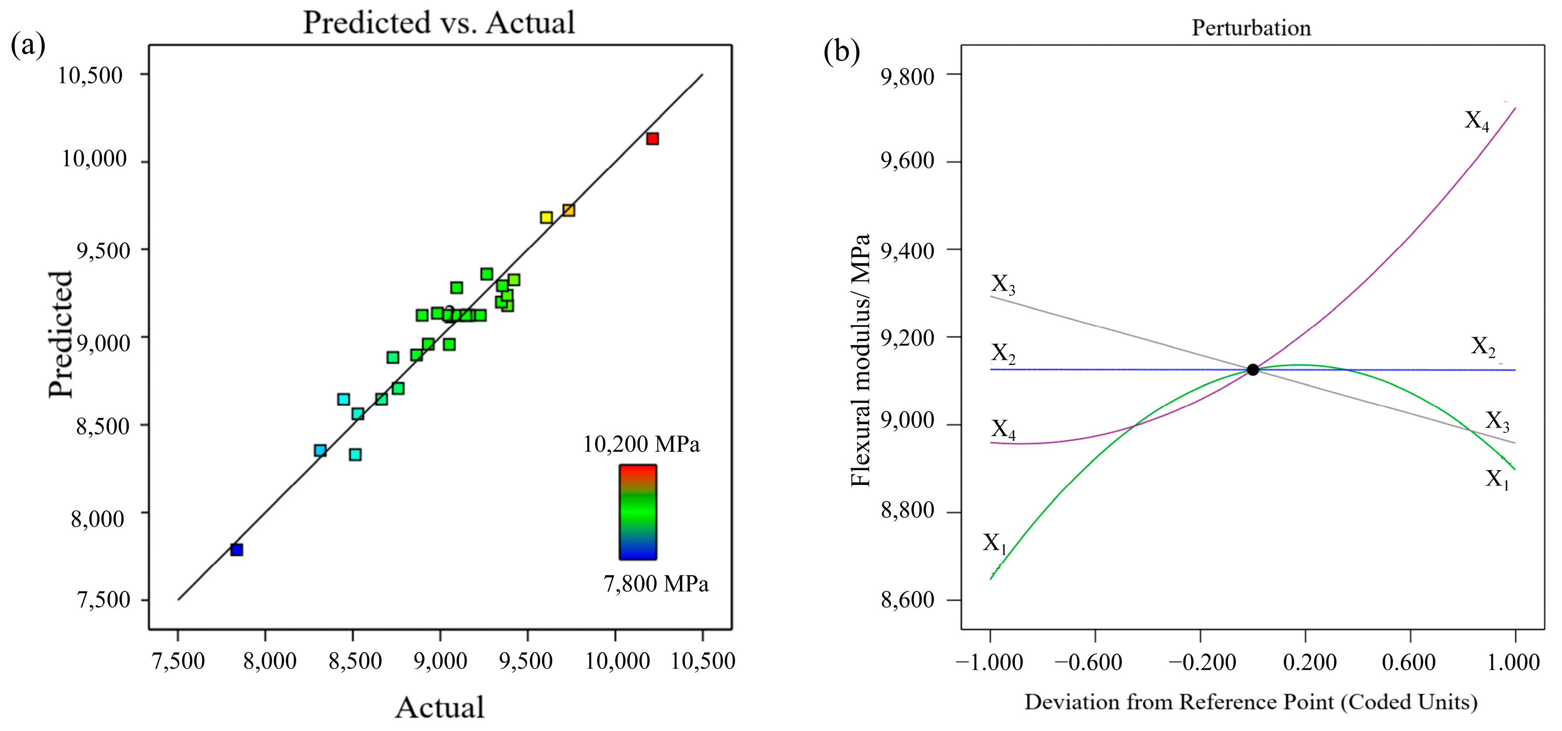
- The flexural modulus of the FDM-printed parts varied in the range of 7836.79–10,213.2 MPa. The three process parameters had a notable impact on the flexural modulus, and the ranking of the degree of influence was as follows: X4 (layer thickness) > X3 (printing speed) > X1 (extrusion temperature). The bed temperature had no significant effect.
- (3)
- The impact strength fluctuated in the range of 17.372–29.701 kJ∙mm−2. The three process parameters had a significant influence on the impact strength, and the order of the degree of influence was X4 (layer thickness) > X3 (printing speed) > X2 (bed temperature). The extrusion temperature has a less significant influence.
- (4)
- The optimal comprehensive mechanical properties obtained from the desirability function outperformed those reported in the literature. The predicted outcomes had a small deviation in the range of 0.890–7.856% compared with the experimental values.
- (5)
- The failure mode of the FDM-printed short carbon fibre-reinforced nylon was a combination of brittle and ductile modes.
- (6)
- Although the filament suppliers recommend ranges of printing parameters, it still necessitates modelling the relationship between the printing parameters and the mechanical properties. The statistical model can help to set the proper printing parameters, specifically aiming to achieve the designed mechanical property in the engineering context.
Author Contributions
Funding
Institutional Review Board Statement
Data Availability Statement
Conflicts of Interest
Appendix A
| Factors and Levels | Responses | ||||||
|---|---|---|---|---|---|---|---|
| Run | Extrusion Temperature/°C (X1) | Bed Temperature/°C (X2) | Printing Speed/mm·s−1 (X3) | Layer Thickness/mm (X4) | Flexural Strength/MPa (Y1) | Flexural Modulus/MPa (Y2) | Impact Strength/kJ·m−2 (Y3) |
| 1 | 300 (−1) | 70 (−1) | 30 (−1) | 0.1 (−1) | 150.41 ± 7.25 | 8529.22 ± 443.09 | 26.3603 ± 3.074 |
| 2 | 320 (1) | 70 (−1) | 30 (−1) | 0.1 (−1) | 157.18 ± 0.68 | 8759.01 ± 188.84 | 28.9077 ± 2.287 |
| 3 | 300 (−1) | 90 (1) | 30 (−1) | 0.1 (−1) | 167.107 ± 2.903 | 8447.47 ± 319.79 | 26.305 ± 0.518 |
| 4 | 320 (1) | 90 (1) | 30 (−1) | 0.1 (−1) | 167.063 ± 8.817 | 9384.82 ± 250.853 | 29.701 ± 1.128 |
| 5 | 300 (−1) | 70 (−1) | 120 (1) | 0.1 (−1) | 134.253 ± 2.61 | 7836.79 ± 247.92 | 22.9577 ± 2.809 |
| 6 | 320 (1) | 70 (−1) | 120 (1) | 0.1 (−1) | 145.387 ± 5.227 | 8314.15 ± 160.95 | 23.7153 ± 2.468 |
| 7 | 300 (−1) | 90 (1) | 120 (1) | 0.1 (−1) | 166.125 ± 2.237 | 8514.36 ± 155.853 | 22.902 ± 0.724 |
| 8 | 320 (1) | 90 (1) | 120 (1) | 0.1 (−1) | 166.823 ± 3.613 | 9093.55 ± 122.393 | 23.888 ± 2.339 |
| 9 | 300 (−1) | 70 (−1) | 30 (−1) | 0.3 (1) | 175.123 ± 2.34 | 10,213.2 ± 57.42 | 20.1823 ± 1.961 |
| 10 | 320 (1) | 70 (−1) | 30 (−1) | 0.3 (1) | 171.517 ± 6.187 | 9606.53 ± 205.83 | 21.4483 ± 0.789 |
| 11 | 300 (−1) | 90 (1) | 30 (−1) | 0.3 (1) | 163.343 ± 8.763 | 9348.74 ± 356.78 | 21.4857 ± 1.443 |
| 12 | 320 (1) | 90 (1) | 30 (−1) | 0.3 (1) | 170.013 ± 3.313 | 8982.67 ± 405.43 | 22.979 ± 1.782 |
| 13 | 300 (−1) | 70 (−1) | 120 (1) | 0.3 (1) | 155.5 ± 1.91 | 9265.45 ± 190.95 | 21.9927 ± 2.065 |
| 14 | 320 (1) | 70 (−1) | 120 (1) | 0.3 (1) | 160.587 ± 1.443 | 9420.72 ± 16.68 | 17.372 ± 1.017 |
| 15 | 300 (−1) | 90 (1) | 120 (1) | 0.3 (1) | 150.417 ± 7.257 | 8729.22 ± 443.09 | 23.0267 ± 2.214 |
| 16 | 320 (1) | 90 (1) | 120 (1) | 0.3 (1) | 162.233 ± 11.383 | 9382.15 ± 200.667 | 19.328 ± 1.858 |
| 17 | 300 (−1) | 80 (0) | 75 (0) | 0.2 (0) | 153.456 ± 3.806 | 8664.42 ± 335.14 | 21.2117 ± 2.576 |
| 18 | 320 (1) | 80 (0) | 75 (0) | 0.2 (0) | 159.21 ± 1.96 | 8864.1 ± 240.87 | 21.597 ± 0.279 |
| 19 | 310 (0) | 70 (−1) | 75 (0) | 0.2 (0) | 154.621 ± 1.08 | 9047.32 ± 3.807 | 22.487 ± 0.595 |
| 20 | 310 (0) | 90 (1) | 75 (0) | 0.2 (0) | 162.735 ± 0.975 | 9096.32 ± 265.967 | 23.948 ± 0.26 |
| 21 | 310 (0) | 80 (0) | 30 (−1) | 0.2 (0) | 161.17 ± 0.64 | 9354.6 ± 328.61 | 24.0013 ± 2.605 |
| 22 | 310 (0) | 80 (0) | 120 (1) | 0.2 (0) | 153.154 ± 5.666 | 9051.18 ± 137.93 | 21.238 ± 4.6 |
| 23 | 310 (0) | 80 (0) | 75 (0) | 0.1 (−0.1) | 153.72 ± 0.83 | 8931.18 ± 128.523 | 24.3037 ± 3.628 |
| 24 | 310 (0) | 80 (0) | 75 (0) | 0.3 (1) | 160.45 ± 2.3 | 9734.39 ± 99.03 | 22.567 ± 2.159 |
| 25 | 310 (0) | 80 (0) | 75 (0) | 0.2 (0) | 156.223 ± 1.963 | 9098.87 ± 291.97 | 21.993 ± 1.193 |
| 26 | 310 (0) | 80 (0) | 75 (0) | 0.2 (0) | 156.38 ± 2.42 | 9228.7 ± 142.61 | 22.619 ± 0.641 |
| 27 | 310 (0) | 80 (0) | 75 (0) | 0.2 (0) | 157.454 ± 4.437 | 8896.32 ± 505.297 | 20.077 ± 2.048 |
| 28 | 310 (0) | 80 (0) | 75 (0) | 0.2 (0) | 154.925 ± 1.757 | 9156.34 ± 479.16 | 21.9472 ± 1.337 |
| 29 | 310 (0) | 80 (0) | 75 (0) | 0.2 (0) | 159.75 ± 4.34 | 9156.34 ± 387.84 | 22.3843 ± 2.144 |
| 30 | 310 (0) | 80 (0) | 75 (0) | 0.2 (0) | 158.537 ± 1.753 | 9166.31 ± 203.78 | 21.818 ± 2.222 |
| 31 | 310 (0) | 80 (0) | 75 (0) | 0.2 (0) | 157.35 ± 1.65 | 9145.62 ± 110.02 | 20.976 ± 2.207 |
Appendix B
The Steps in Calculating the Entropy Weight
| Sample Number | Flexural Strength | Flexural Modulus | Impact Strength |
|---|---|---|---|
| 1 | 0.395 | 0.291 | 0.729 |
| 2 | 0.561 | 0.388 | 0.936 |
| 3 | 0.804 | 0.257 | 0.725 |
| 4 | 0.803 | 0.651 | 1.000 |
| 5 | 0.000 | 0.000 | 0.453 |
| 6 | 0.272 | 0.201 | 0.515 |
| 7 | 0.780 | 0.285 | 0.449 |
| 8 | 0.797 | 0.529 | 0.529 |
| 9 | 1.000 | 1.000 | 0.228 |
| 10 | 0.912 | 0.745 | 0.331 |
| 11 | 0.712 | 0.636 | 0.334 |
| 12 | 0.875 | 0.482 | 0.455 |
| 13 | 0.520 | 0.601 | 0.375 |
| 14 | 0.644 | 0.667 | 0.000 |
| 15 | 0.395 | 0.376 | 0.459 |
| 16 | 0.685 | 0.650 | 0.159 |
| 17 | 0.470 | 0.348 | 0.311 |
| 18 | 0.611 | 0.432 | 0.343 |
| 19 | 0.498 | 0.509 | 0.415 |
| 20 | 0.697 | 0.530 | 0.533 |
| 21 | 0.659 | 0.639 | 0.538 |
| 22 | 0.462 | 0.511 | 0.314 |
| 23 | 0.476 | 0.461 | 0.562 |
| 24 | 0.641 | 0.799 | 0.421 |
| 25 | 0.538 | 0.531 | 0.375 |
| 26 | 0.541 | 0.586 | 0.426 |
| 27 | 0.568 | 0.446 | 0.219 |
| 28 | 0.506 | 0.555 | 0.371 |
| 29 | 0.624 | 0.555 | 0.407 |
| 30 | 0.594 | 0.559 | 0.361 |
| Flexural Strength | Flexural Modulus | Impact Strength | |
|---|---|---|---|
| ej | 0.981535639 | 0.977272659 | 0.969724355 |
| dj | 0.018464361 | 0.022727341 | 0.030275645 |
| wj | 0.2584 | 0.3180 | 0.4236 |
References
- Wei, N. Investigation of Process-Structure-Performance Relation for Polymeric Composites by Fused Deposition Modeling. Ph.D. Thesis, Central South University, Changsha, China, 2023. (In Chinese) [Google Scholar] [CrossRef]
- de Toro, E.V.; Sobrino, J.C.; Martínez, A.M.; Eguía, V.M. Analysis of the influence of the variables of the Fused Deposition Modeling (FDM) process on the mechanical properties of a carbon fiber-reinforced polyamide. Procedia Manuf. 2019, 41, 731–738. [Google Scholar] [CrossRef]
- Beylergil, B.; Al-Nadhari, A.; Yildiz, M. Optimization of Charpy-impact strength of 3D-printed carbon fiber/polyamide composites by Taguchi method. Polym. Compos. 2023, 44, 2846–2859. [Google Scholar] [CrossRef]
- Alafaghani, A.A.; Qattawi, A.; Alrawi, B.; Guzman, A. Experimental optimization of fused deposition modelling processing parameters: A design-for-manufacturing approach. Procedia Manuf. 2017, 10, 791–803. [Google Scholar] [CrossRef]
- Shanmugam, V.; Babu, K.; Kannan, G.; Mensah, R.A.; Samantaray, S.K.; Das, O. The thermal properties of FDM printed polymeric materials: A review. Polym. Degrad. Stab. 2024, 228, 110902. [Google Scholar] [CrossRef]
- Rashed, K.; Kafi, A.; Simons, R.; Bateman, S. Fused filament fabrication of nylon 6/66 copolymer: Parametric study comparing full factorial and Taguchi design of experiments. Rapid Prototyp. J. 2022, 28, 1111–1128. [Google Scholar] [CrossRef]
- Wickramasinghe, S.; Do, T.; Tran, P. FDM-based 3D printing of polymer and associated composite: A review on mechanical properties, defects and treatments. Polymers 2020, 12, 1529. [Google Scholar] [CrossRef]
- Ranjan, R.; Saha, A. A novel hybrid multi-criteria optimization of 3D printing process using grey relational analysis (GRA) coupled with principal component analysis (PCA). Eng. Res. Express 2024, 6, 015080. [Google Scholar] [CrossRef]
- Li, Y.H.; Dong, Q.; Tai, Q.A.; Gao, S.Y.; Guan, H.; Yan, W. Mechanical properties of carbon fiber composite in fused deposition modeling of additive manufacturing. J. Plast. Eng. 2017, 24, 225–230. [Google Scholar]
- Karimi, A.; Rahmatabadi, D.; Baghani, M. Various FDM mechanisms used in the fabrication of continuous-fiber reinforced composites: A review. Polymers 2024, 16, 831. [Google Scholar] [CrossRef]
- Gómez-Ortega, A.; Piedra, S.; Mondragón-Rodríguez, G.C.; Camacho, N. Dependence of the mechanical properties of nylon-carbon fiber composite on the FDM printing parameters. Compos. Part A Appl. Sci. Manuf. 2024, 186, 108419. [Google Scholar] [CrossRef]
- Ahmad, N.N.; Wong, Y.H.; Ghazali, N.N.N. A systematic review of fused deposition modeling process parameters. Soft Sci. 2022, 2, 11. [Google Scholar] [CrossRef]
- Marwah, O.M.F.; Yahaya, N.F.; Darsani, A.; Mohamad, E.J.; Haq, R.H.A.; Johar, M.A.; Othman, M.H. Investigation for shrinkage deformation in the desktop 3D printer process by using DOE approach of the ABS materials. J. Phys. Conf. Ser. 2019, 1150, 012038. [Google Scholar] [CrossRef]
- Belei, C.; Joeressen, J.; Amancio-Filho, S.T. Fused-filament fabrication of short carbon fiber-reinforced polyamide: Parameter optimization for improved performance under uniaxial tensile loading. Polymers 2022, 14, 1292. [Google Scholar] [CrossRef] [PubMed]
- Palaniappan, A.K.; Krishnan, R.K.; Vasanaperumal, P.; Rajendiran, K. Analysis of the Mechanical Characteristics and Properties of a Carbon Fiber-Nylon Composite Influence of the Factors of the Fused Deposition Modeling. J. Mater. Eng. Perform. 2024, 33, 12976–12989. [Google Scholar] [CrossRef]
- Hartomacioğlu, S. Optimization of Production Parameters for Impact Strength of 3D-Printed Carbon/Glass Fiber-Reinforced Nylon Composite in Critical ZX Printing Orientation. Polymers 2024, 16, 3006. [Google Scholar] [CrossRef]
- Tunçel, O.; Kahya, Ç.; Tüfekci, K. Optimization of flexural performance of PETG samples produced by fused filament fabrication with response surface method. Polymers 2024, 16, 2020. [Google Scholar] [CrossRef]
- Ahmed, H.; Hussain, G.; Gohar, S.; Ali, A.; Alkahtani, M. Impact toughness of hybrid carbon fiber-PLA/ABS laminar composite produced through fused filament fabrication. Polymers 2021, 13, 3057. [Google Scholar] [CrossRef]
- Equbal, A.; Equbal, M.A.; Ahmad, R.; Kumar, M.; Hrishikesh; Khan, O.; Yahya, Z.; Alhodaib, A.; Yadav, A.K. RSM-Based Statistical Approach to Enhance the Compressive Performance of ABS P400 Parts Fabricated via FDM Technology. Surf. Rev. Lett. 2024, 2550021. [Google Scholar] [CrossRef]
- Podstawczyk, D.; Witek-Krowiak, A.; Dawiec, A.; Bhatnagar, A. Biosorption of copper (II) ions by flax meal: Empirical modeling and process optimization by response surface methodology (RSM) and artificial neural network (ANN) simulation. Ecol. Eng. 2015, 83, 364–379. [Google Scholar] [CrossRef]
- Liu, X.; Zhang, M.; Li, S.; Si, L.; Peng, J.; Hu, Y. Mechanical property parametric appraisal of fused deposition modeling parts based on the gray Taguchi method. Int. J. Adv. Manuf. Technol. 2017, 89, 2387–2397. [Google Scholar] [CrossRef]
- Bakhtiari, H.; Nikzad, M.; Tolouei-Rad, M. Influence of three-dimensional printing parameters on compressive properties and surface smoothness of polylactic acid specimens. Polymers 2023, 15, 3827. [Google Scholar] [CrossRef] [PubMed]
- Snapp, K.L.; Gongora, A.E.; Brown, K.A. Increasing throughput in fused deposition modeling by modulating bed temperature. J. Manuf. Sci. Eng. 2021, 143, 094502. [Google Scholar] [CrossRef]
- Abbott, A.C.; Tandon, G.P.; Bradford, R.L.; Koerner, H.; Baur, J.W. Process-structure-property effects on ABS bond strength in fused filament fabrication. Addit. Manuf. 2018, 19, 29–38. [Google Scholar] [CrossRef]
- Wang, P.; Zou, B.; Ding, S.; Li, L.; Huang, C. Effects of FDM-3D printing parameters on mechanical properties and microstructure of CF/PEEK and GF/PEEK. Chin. J. Aeronaut. 2021, 34, 236–246. [Google Scholar] [CrossRef]
- Kechagias, J.; Zaoutsos, S. Effects of 3D-printing processing parameters on FFF parts’ porosity: Outlook and trends. Mater. Manuf. Process. 2024, 39, 804–814. [Google Scholar] [CrossRef]
- Dul, S.; Fambri, L.; Pegoretti, A. High-performance polyamide/carbon fiber composites for fused filament fabrication: Mechanical and functional performances. J. Mater. Eng. Perform. 2021, 30, 5066–5085. [Google Scholar] [CrossRef]
- Kechagias, J.D.; Zaoutsos, S.P.; Chaidas, D.; Vidakis, N. Multi-parameter optimization of PLA/Coconut wood compound for Fused Filament Fabrication using Robust Design. Int. J. Adv. Manuf. Technol. 2022, 119, 4317–4328. [Google Scholar] [CrossRef]
- Heller, B.P.; Smith, D.E.; Jack, D.A. Effects of extrudate swell and nozzle geometry on fiber orientation in Fused Filament Fabrication nozzle flow. Addit. Manuf. 2016, 12, 252–264. [Google Scholar] [CrossRef]
- Soundararajan, R.; Ramesh, A.; Mohanraj, N.; Parthasarathi, N. An investigation of material removal rate and surface roughness of squeeze casted A413 alloy on WEDM by multi response optimization using RSM. J. Alloys Compd. 2016, 685, 533–545. [Google Scholar] [CrossRef]
- Garzon-Hernandez, S.; Arias, A.; Garcia-Gonzalez, D. A continuum constitutive model for FDM 3D printed thermoplastics. Compos. Part B Eng. 2020, 201, 108373. [Google Scholar] [CrossRef]
- Basavaraj, C.K.; Vishwas, M. Studies on effect of fused deposition modelling process parameters on ultimate tensile strength and dimensional accuracy of nylon. In IOP Conference Series: Materials Science and Engineering; IOP Publishing: Bristol, UK, 2016; Volume 149, p. 012035. [Google Scholar]
- Cao, Y.; Chen, C.; Xu, S.; Zhao, R.; Guo, K.; Hu, T.; Liao, H.; Wang, J.; Ren, Z. Machine learning assisted prediction and optimization of mechanical properties for laser powder bed fusion of Ti6Al4V alloy. Addit. Manuf. 2024, 91, 104341. [Google Scholar] [CrossRef]
- Yang, F.; Li, R.; Wang, X.; Cheng, B.; Gu, R. Optimization of working parameters of high-pressure roller mill based on entropy weight method and response surface method. Sci. Rep. 2024, 14, 28238. [Google Scholar] [CrossRef] [PubMed]
- Lei, X.; Ouyang, H.; Xu, L. Image segmentation based on equivalent three-dimensional entropy method and artificial fish swarm optimization algorithm. Opt. Eng. 2018, 57, 103106. [Google Scholar] [CrossRef]
- Kumar, R.; Bilga, P.S.; Singh, S. Multi objective optimization using different methods of assigning weights to energy consumption responses, surface roughness and material removal rate during rough turning operation. J. Clean. Prod. 2017, 164, 45–57. [Google Scholar] [CrossRef]
- Taheriyoun, M.; Karamouz, M.; Baghvand, A. Development of an entropy-based fuzzy eutrophication index for reservoir water quality evaluation. J. Environ. Health Sci. Eng. 2010, 7, 1–14. [Google Scholar]
- Kariuki, L.W.; Ikua, B.W.; Karanja, S.K.; Ng’ang’a, S.P.; Zeidler, H. Fused filament fabrication of carbon fiber-reinforced polymer composite: Effect of process parameters on flexural properties. Eng. Rep. 2024, 6, e12807. [Google Scholar] [CrossRef]
- Balaji, N.S.; Velmurugan, C.; Saravana Kumar, M.; Sivakumar, M.; Asokan, P. Experimental investigation on mechanical properties of fdm-based nylon carbon parts using ann approach. Surf. Rev. Lett. 2023, 30, 2350028. [Google Scholar] [CrossRef]
- Zhang, H.; Sun, W.F. Mechanical properties and failure behavior of 3D printed thermoplastic composites using continuous basalt fiber under high-volume fraction. Def. Technol. 2023, 27, 237–250. [Google Scholar] [CrossRef]
- Yang, D.; Zhang, H.; Wu, J.; McCarthy, E.D. Fibre flow and void formation in 3D printing of short-fibre reinforced thermoplastic composites: An experimental benchmark exercise. Addit. Manuf. 2021, 37, 101686. [Google Scholar] [CrossRef]
- Palaniappan, A.K.; Arockiasamy, F.S.; Rajesh, S.; Karthick, U. Investigating the Parameters of Carbon Fiber Nylon Composites Using the Fused Deposition Modeling Process to Determine the Mechanical Characteristics and Properties of the Composites. J. Mater. Eng. Perform. 2025. [Google Scholar] [CrossRef]



| Source | Sum of Squares | DF | Mean Square | F-Value | p-Value | Contribution (%) |
|---|---|---|---|---|---|---|
| Model | 1797.07 | 8 | 225 | 34.2 | <0.0001 | 92.56 |
| X1 | 108.92 | 1 | 109 | 16.59 | 0.0005 | 5.61 |
| X2 | 282.28 | 1 | 282.28 | 42.98 | <0.0001 | 14.54 |
| X3 | 434.6 | 1 | 435 | 66.18 | <0.0001 | 22.38 |
| X4 | 207.5 | 1 | 208 | 31.6 | <0.0001 | 10.69 |
| X2X3 | 83.61 | 1 | 83.6 | 12.73 | 0.0017 | 4.31 |
| X2X4 | 583.33 | 1 | 583 | 88.82 | <0.0001 | 30.04 |
| X3X4 | 30.49 | 1 | 30.5 | 4.64 | 0.0424 | 1.57 |
| X22 | 66.33 | 1 | 66.3 | 10.1 | 0.0044 | 3.42 |
| Residual | 144.48 | 22 | 6.57 | - | - | 7.44 |
| Lack of Fit | 129.31 | 16 | 8.08 | 3.2 | 0.0791 | 6.66 |
| Pure Error | 15.17 | 6 | 2.53 | - | - | 0.78 |
| Cor Total | 1941.55 | 30 | - | - | - | 100 |
| Source | Sum of Squares | DF | Mean Square | F-Value | p-Value | Contribution (%) |
|---|---|---|---|---|---|---|
| Model | 5.78 × 10⁶ | 11 | 5.26 × 10⁵ | 27.11 | <0.0001 | 93.98 |
| X1 | 2.84 × 10⁵ | 1 | 2.84 × 10⁵ | 14.62 | 0.0011 | 4.62 |
| X2 | 9.52 | 1 | 9.52 | 0.0005 | 0.9826 | 0.00 |
| X3 | 5.06 × 10⁵ | 1 | 5.06 × 10⁵ | 26.11 | <0.0001 | 8.23 |
| X4 | 2.62 × 10⁶ | 1 | 2.62 × 10⁶ | 135.36 | <0.0001 | 42.60 |
| X1X2 | 1.50 × 10⁵ | 1 | 1.50 × 10⁵ | 7.72 | 0.012 | 2.44 |
| X1X3 | 1.74 × 10⁵ | 1 | 1.74 × 10⁵ | 9 | 0.0074 | 2.83 |
| X1X4 | 3.57 × 10⁵ | 1 | 3.57 × 10⁵ | 18.39 | 0.0004 | 5.80 |
| X2X3 | 2.09 × 10⁵ | 1 | 2.09 × 10⁵ | 10.75 | 0.0039 | 3.40 |
| X2X4 | 1.03 × 10⁶ | 1 | 1.03 × 10⁶ | 53.25 | <0.0001 | 16.75 |
| X12 | 4.32 × 10⁵ | 1 | 4.32 × 10⁵ | 22.3 | 0.0001 | 7.02 |
| X42 | 1.61 × 10⁵ | 1 | 1.61 × 10⁵ | 8.32 | 0.0095 | 2.62 |
| Residual | 3.68 × 10⁵ | 19 | 19,385.45 | - | - | 5.98 |
| Lack of Fit | 3.01 × 10⁵ | 13 | 23,122.83 | 2.05 | 0.194 | 4.89 |
| Pure Error | 67,726.78 | 6 | 11,287.8 | - | - | 1.10 |
| Cor Total | 6.15 × 10⁶ | 30 | - | - | - | 100 |
| Source | Sum of Squares | DF | Mean Square | F-Value | p-Value | Contribution (%) |
|---|---|---|---|---|---|---|
| Model | 171 | 8 | 21.4 | 25.22 | <0.0001 | 90.27 |
| X1 | 0.351 | 1 | 0.351 | 0.4142 | 0.5265 | 0.19 |
| X2 | 3.68 | 1 | 3.68 | 4.35 | 0.0488 | 1.94 |
| X3 | 34.6 | 1 | 34.6 | 40.86 | <0.0001 | 18.26 |
| X4 | 83 | 1 | 83 | 98.08 | <0.0001 | 43.81 |
| X1X3 | 14.6 | 1 | 14.6 | 17.24 | 0.0004 | 7.71 |
| X1X4 | 11 | 1 | 11 | 12.96 | 0.0016 | 5.81 |
| X3X4 | 11.3 | 1 | 11.3 | 13.33 | 0.0014 | 5.96 |
| X42 | 12.3 | 1 | 12.3 | 14.57 | 0.0009 | 6.49 |
| Residual | 18.6 | 22 | 0.847 | - | - | 9.82 |
| Lack of Fit | 14 | 16 | 0.875 | 1.13 | 0.4704 | 7.39 |
| Pure Error | 4.63 | 6 | 0.772 | - | - | 2.44 |
| Cor Total | 189.44 | 30 | - | - | - | 100 |
| Optimal Process Parameter Combination | Mechanical Properties | ||||||
|---|---|---|---|---|---|---|---|
| Extrusion Temperature/°C | Bed Temperature/°C | Printing Speed/ mm∙s−1 | layer Thickness/mm | Flexural Strength/mpa | Flexural Modulus/ mpa | Impact Strength/ kJ∙m−2 | |
| 318 | 90 | 30 | 0.1 | 1 | 173.107 | 9484.739 | 27.785 |
| 2 | 166.736 | 9321.681 | 26.561 | ||||
| 3 | 165.264 | 9217.148 | 27.642 | ||||
| Average value | 168.369 | 9341.189 | 27.329 | ||||
| Mechanical Properties | Process Parameters | References | |
|---|---|---|---|
| Variable Factors | Fixed Factors | ||
| Maximum flexural strength: 67.36 ± 6.84 MPa Maximum flexural modulus: 2783.35 ± 346.9 MPa | Extrusion temperature: 230–280 °C, wall thick: 0.8–1.6 mm, infill density: 33–99% | Nozzle diameter: 0.4 mm, layer thickness: 0.2 mm, printing speed: 50∙mm∙s−1, infill pattern: rectilinear | [11] |
| Maximum flexural strength: 119.9 MPa Maximum flexural modulus: 3038 MPa | Printing speed: 30–50 mm∙s−1, layer thickness: 0.1–0.2 mm, extrusion temperature: 270–290 °C, build orientation: flat, on-edge | Infill pattern: rectilinear, infill density: 100%, raster angle: ±45°, bed temperature: 80 °C, nozzle diameter: 0.4 mm | [38] |
| Maximum flexural strength: 25.89 MPa Maximum impact strength: 0.72 kJ∙mm−2 | Layer thickness: 0.1–0.3 mm, printing speed: 40–60 mm∙s−1, infill density: 60–100% | Not mentioned | [15] |
| Maximum impact strength: 10.54 kJ∙mm−2 | Extrusion temperature: 240–260 °C, printing speed: 20–40 mm∙s−1, infill density: 80–100%, raster angle: 0–75° | Bed temperature: 80 °C, Nozzle diameter: 0.4 mm, layer thickness: 0.2 mm | [3] |
| Maximum flexural strength: 87 MPa Maximum impact strength: 12.5 kJ∙mm−2 | Layer thickness: 0.07–0.2 mm, infill density: 50–100%, raster angle: 0–90° | Extrusion temperature: 215 °C, bed temperature: 110 °C, infill pattern: zig-zag | [39] |
| Maximum impact strength: 6.258 kJ∙mm−2 | Extrusion temperature: 245–275 °C, layer thickness: 0.15–0.45 mm, wall line count: 0–2, heat treatment time: 0–160 min | Nozzle diameter: 0.6 mm, initial layer height: 0.25 mm, infill density: 100%, infill pattern: lines, bed temperature: 70 °C, printing speed: 40 mm∙s−1 | [16] |
| Maximum flexural strength = 175.123 MPa, Maximum flexural modulus = 10,213.2 MPa, Maximum impact strength = 29.701 kJ∙mm−2 | Extrusion temperature: 300–320 °C, bed temperature: 70–90 °C, printing speed: 30–120 mm∙s−1, layer thickness: 0.1–0.3 mm, | Infill pattern: concentric, infill density: 100%, nozzle diameter: 0.6 mm | This work |
| Optimal comprehensive mechanical properties: flexural strength = 168.369 MPa, flexural modulus = 9341.189 MPa, impact strength = 27.329 kJ∙mm−2 | |||
Disclaimer/Publisher’s Note: The statements, opinions and data contained in all publications are solely those of the individual author(s) and contributor(s) and not of MDPI and/or the editor(s). MDPI and/or the editor(s) disclaim responsibility for any injury to people or property resulting from any ideas, methods, instructions or products referred to in the content. |
© 2025 by the authors. Licensee MDPI, Basel, Switzerland. This article is an open access article distributed under the terms and conditions of the Creative Commons Attribution (CC BY) license (https://creativecommons.org/licenses/by/4.0/).
Share and Cite
Fang, Q.; Yu, J.; Shi, B. Modelling and Optimisation of FDM-Printed Short Carbon Fibre-Reinforced Nylon Using CCF and RSM. Polymers 2025, 17, 1872. https://doi.org/10.3390/polym17131872
Fang Q, Yu J, Shi B. Modelling and Optimisation of FDM-Printed Short Carbon Fibre-Reinforced Nylon Using CCF and RSM. Polymers. 2025; 17(13):1872. https://doi.org/10.3390/polym17131872
Chicago/Turabian StyleFang, Qibin, Jing Yu, and Bowen Shi. 2025. "Modelling and Optimisation of FDM-Printed Short Carbon Fibre-Reinforced Nylon Using CCF and RSM" Polymers 17, no. 13: 1872. https://doi.org/10.3390/polym17131872
APA StyleFang, Q., Yu, J., & Shi, B. (2025). Modelling and Optimisation of FDM-Printed Short Carbon Fibre-Reinforced Nylon Using CCF and RSM. Polymers, 17(13), 1872. https://doi.org/10.3390/polym17131872


