
The Nanomechanical Performance and Water Uptake of a Flowable Short Fiber Composite: The Influence of Bulk and Layering Restorative Techniques

 , , , , ,
 ,
,  and
and 
Abstract
1. Introduction
2. Materials and Methods
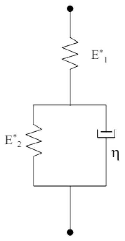
2.1. Nanoindentation Protocol
2.2. Nanoindentation Creep
2.3. Water Degradation and Uptake
2.4. Surface Morphology and Characterization
2.5. Statistical Analysis
3. Results
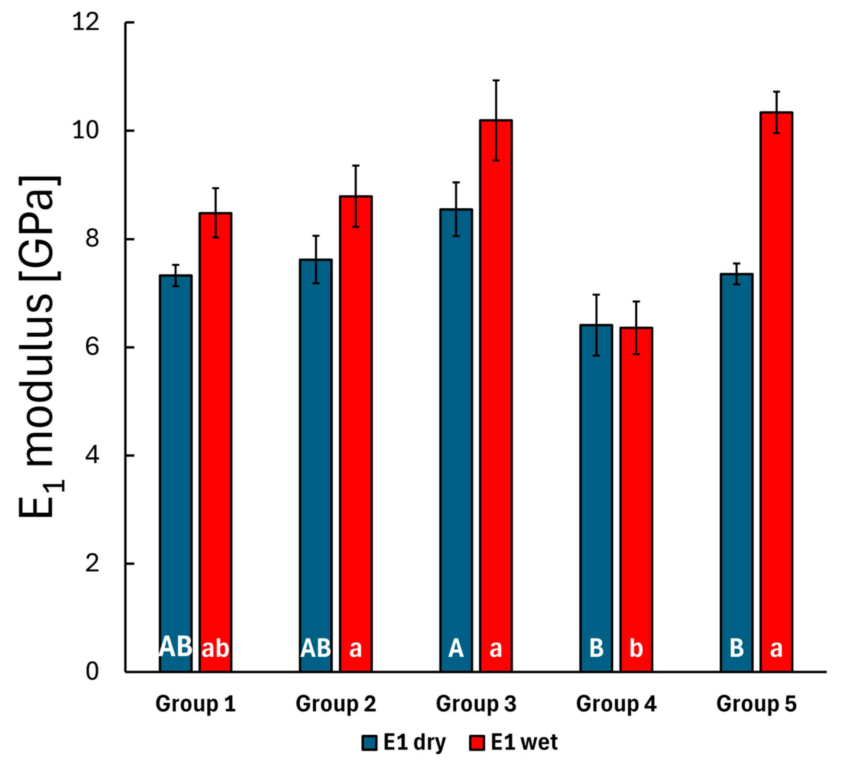
3.1. Static Nanoindentation
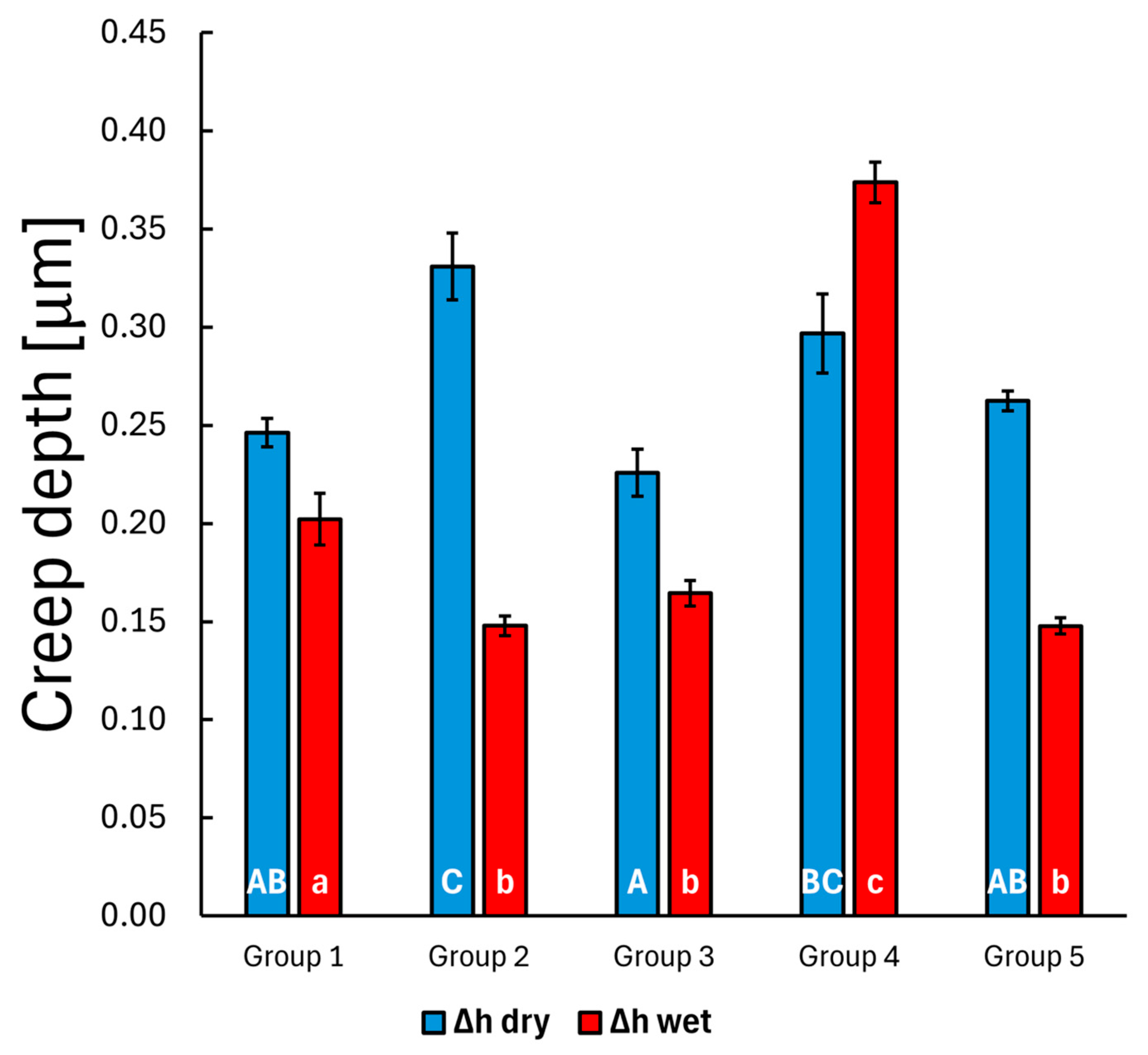
3.2. Creep Nanoindentation
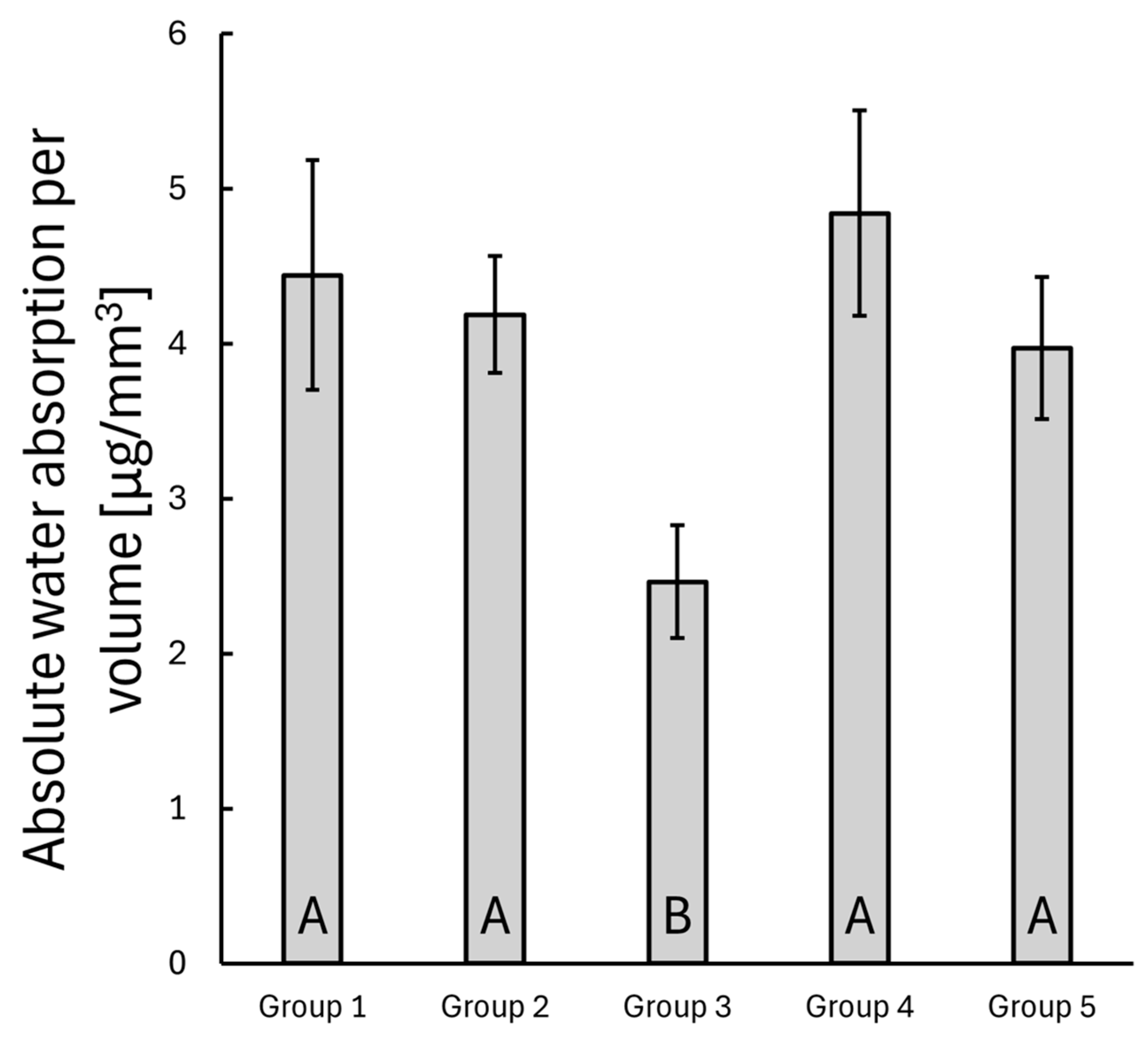
3.3. Water Uptake
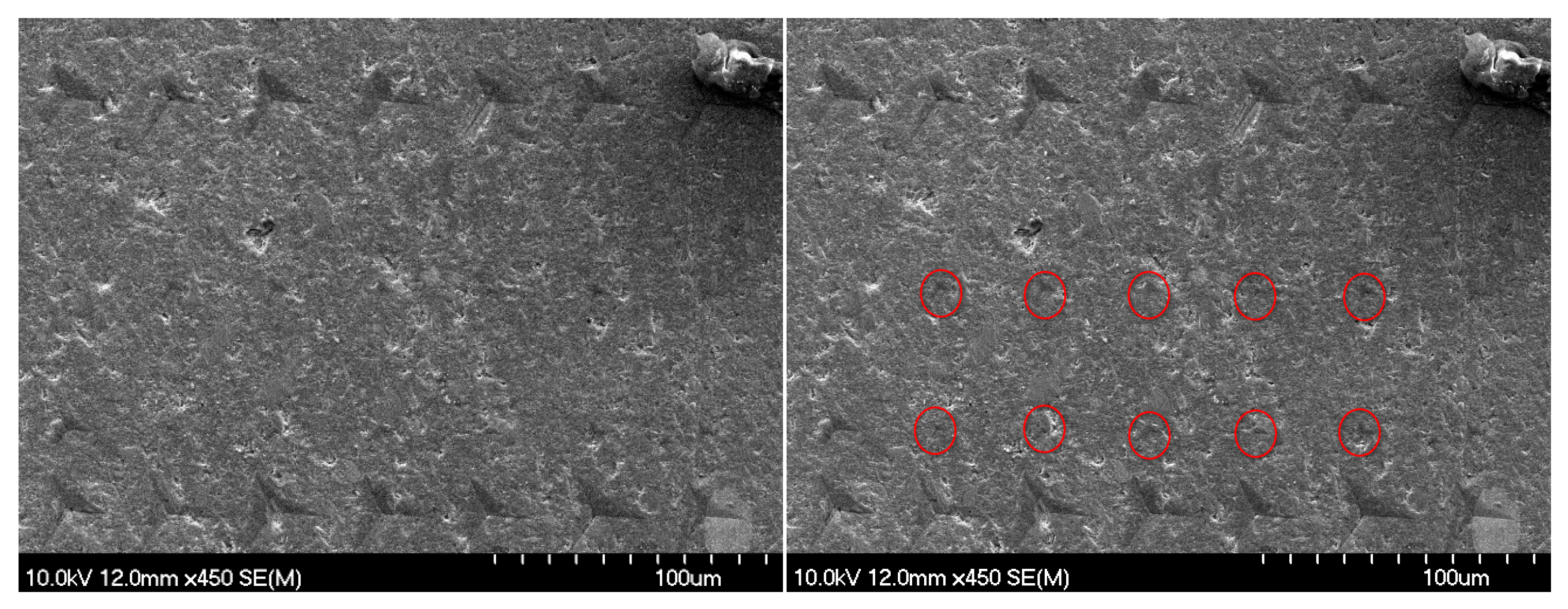
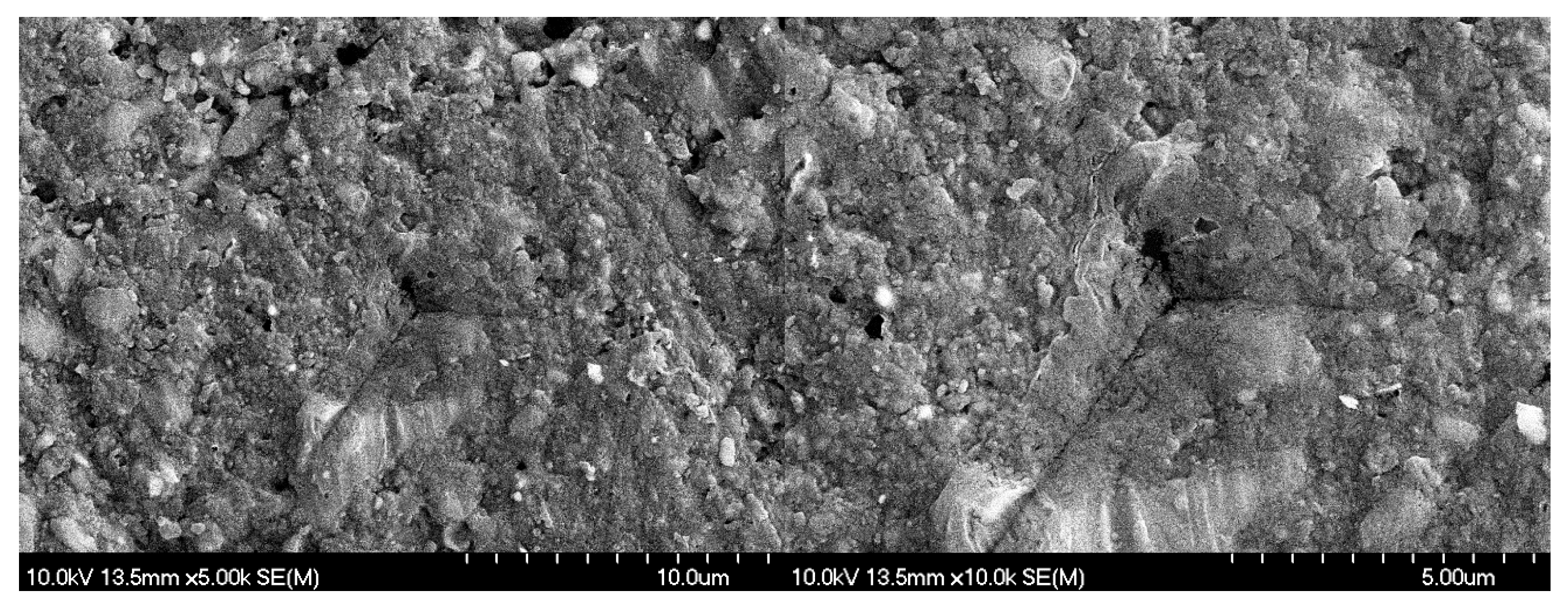
3.4. SEM Evaluation
4. Discussion
5. Conclusions
Author Contributions
Funding
Institutional Review Board Statement
Data Availability Statement
Conflicts of Interest
References
- Bonilla, E.D.; Hayashi, M.; Pameijer, C.H.; Le, N.V.; Morrow, B.R.; Garcia-Godoy, F. The Effect of Two Composite Placement Techniques on Fracture Resistance of MOD Restorations with Various Resin Composites. J. Dent. 2020, 101, 103348. [Google Scholar] [CrossRef] [PubMed]
- Haak, R.; Näke, T.; Park, K.-J.; Ziebolz, D.; Krause, F.; Schneider, H. Internal and Marginal Adaptation of High-Viscosity Bulk-Fill Composites in Class II Cavities Placed with Different Adhesive Strategies. Odontology 2019, 107, 374–382. [Google Scholar] [CrossRef] [PubMed]
- Manhart, J.; Scheibenbogen-Fuchsbrunner, A.; Chen, H.Y.; Hickel, R. A 2-Year Clinical Study of Composite and Ceramic Inlays. Clin. Oral Investig. 2000, 4, 192–198. [Google Scholar] [CrossRef] [PubMed]
- Demarco, F.F.; Corrêa, M.B.; Cenci, M.S.; Moraes, R.R.; Opdam, N.J.M. Longevity of Posterior Composite Restorations: Not Only a Matter of Materials. Dent. Mater. 2012, 28, 87–101. [Google Scholar] [CrossRef]
- Bernardo, M.; Luis, H.; Martin, M.D.; Leroux, B.G.; Rue, T.; Leitão, J.; DeRouen, T.A. Survival and Reasons for Failure of Amalgam versus Composite Posterior Restorations Placed in a Randomized Clinical Trial. J. Am. Dent. Assoc. 2007, 138, 775–783. [Google Scholar] [CrossRef]
- Demarco, F.F.; Cenci, M.S.; Montagner, A.F.; De Lima, V.P.; Correa, M.B.; Moraes, R.R.; Opdam, N.J.M. Longevity of Composite Restorations Is Definitely Not Only about Materials. Dent. Mater. 2023, 39, 1–12. [Google Scholar] [CrossRef]
- Da Rosa Rodolpho, P.A.; Donassollo, T.A.; Cenci, M.S.; Loguércio, A.D.; Moraes, R.R.; Bronkhorst, E.M.; Opdam, N.J.M.; Demarco, F.F. 22-Year Clinical Evaluation of the Performance of Two Posterior Composites with Different Filler Characteristics. Dent. Mater. 2011, 27, 955–963. [Google Scholar] [CrossRef]
- Gaeta, C.; Marruganti, C.; Mignosa, E.; Franciosi, G.; Ferrari, E.; Grandini, S. Influence of Methodological Variables on Fracture Strength Tests Results of Premolars with Different Number of Residual Walls. A Systematic Review with Meta-Analysis. Dent. J. 2021, 9, 146. [Google Scholar] [CrossRef]
- Patel, S.; Bhuva, B.; Bose, R. Present Status and Future Directions: Vertical Root Fractures in Root Filled Teeth. Int. Endod. J. 2022, 55, 804–826. [Google Scholar] [CrossRef]
- Valizadeh, S.; Ranjbar Omrani, L.; Deliperi, S.; Sadeghi Mahounak, F. Restoration of a Nonvital Tooth with Fiber Reinforce Composite (Wallpapering Technique). Case Rep. Dent. 2020, 2020, 9619787. [Google Scholar] [CrossRef]
- Lempel, E.; Szebeni, D.; Őri, Z.; Kiss, T.; Szalma, J.; Lovász, B.V.; Kunsági-Máté, S.; Böddi, K. The Effect of High-Irradiance Rapid Polymerization on Degree of Conversion, Monomer Elution, Polymerization Shrinkage and Porosity of Bulk-Fill Resin Composites. Dent. Mater. 2023, 39, 442–453. [Google Scholar] [CrossRef] [PubMed]
- Ohmori, K.; Tasaki, T.; Kimura, S.; Hori, A.; Sakaeda, N.; Hanabusa, M.; Yamamoto, T. Residual Polymerization Stresses in Human Premolars Generated with Class II Composite Restorations. J. Mech. Behav. Biomed. Mater. 2020, 104, 103643. [Google Scholar] [CrossRef] [PubMed]
- Sadr, A.; Bakhtiari, B.; Hayashi, J.; Luong, M.N.; Chen, Y.-W.; Chyz, G.; Chan, D.; Tagami, J. Effects of Fiber Reinforcement on Adaptation and Bond Strength of a Bulk-Fill Composite in Deep Preparations. Dent. Mater. 2020, 36, 527–534. [Google Scholar] [CrossRef] [PubMed]
- Tseng, P.-C.; Chuang, S.-F.; Kaisarly, D.; Kunzelmann, K.-H. Simulating the Shrinkage-Induced Interfacial Damage around Class I Composite Resin Restorations with Damage Mechanics. Dent. Mater. 2023, 39, 513–521. [Google Scholar] [CrossRef]
- Tsertsidou, V.; Mourouzis, P.; Dionysopoulos, D.; Pandoleon, P.; Tolidis, K. Fracture Resistance of Class II MOD Cavities Restored by Direct and Indirect Techniques and Different Materials Combination. Polymers 2023, 15, 3413. [Google Scholar] [CrossRef]
- Fráter, M.; Sáry, T.; Jókai, B.; Braunitzer, G.; Säilynoja, E.; Vallittu, P.K.; Lassila, L.; Garoushi, S. Fatigue Behavior of Endodontically Treated Premolars Restored with Different Fiber-Reinforced Designs. Dent. Mater. 2021, 37, 391–402. [Google Scholar] [CrossRef]
- Lassila, L.; Keulemans, F.; Säilynoja, E.; Vallittu, P.K.; Garoushi, S. Mechanical Properties and Fracture Behavior of Flowable Fiber Reinforced Composite Restorations. Dent. Mater. 2018, 34, 598–606. [Google Scholar] [CrossRef]
- Yang, J.; Silikas, N.; Watts, D.C. Polymerization and Shrinkage Kinetics and Fracture Toughness of Bulk-Fill Resin-Composites. Dent. Mater. 2022, 38, 1934–1941. [Google Scholar] [CrossRef]
- Heintze, S.D.; Ilie, N.; Hickel, R.; Reis, A.; Loguercio, A.; Rousson, V. Laboratory Mechanical Parameters of Composite Resins and Their Relation to Fractures and Wear in Clinical Trials—A Systematic Review. Dent. Mater. 2017, 33, e101–e114. [Google Scholar] [CrossRef]
- Manhart, J.; Kunzelmann, K.-H.; Chen, H.Y.; Hickel, R. Mechanical Properties and Wear Behavior of Light-Cured Packable Composite Resins. Dent. Mater. 2000, 16, 33–40. [Google Scholar] [CrossRef]
- Lassila, L.; Säilynoja, E.; Prinssi, R.; Vallittu, P.K.; Garoushi, S. Fracture Behavior of Bi-Structure Fiber-Reinforced Composite Restorations. J. Mech. Behav. Biomed. Mater. 2020, 101, 103444. [Google Scholar] [CrossRef] [PubMed]
- Garoushi, S.; Säilynoja, E.; Vallittu, P.K.; Lassila, L. Physical Properties and Depth of Cure of a New Short Fiber Reinforced Composite. Dent. Mater. 2013, 29, 835–841. [Google Scholar] [CrossRef] [PubMed]
- Sáry, T.; Garoushi, S.; Braunitzer, G.; Alleman, D.; Volom, A.; Fráter, M. Fracture Behaviour of MOD Restorations Reinforced by Various Fibre-Reinforced Techniques—An in Vitro Study. J. Mech. Behav. Biomed. Mater. 2019, 98, 348–356. [Google Scholar] [CrossRef] [PubMed]
- Lassila, L.; Säilynoja, E.; Prinssi, R.; Vallittu, P.; Garoushi, S. Characterization of a New Fiber-Reinforced Flowable Composite. Odontology 2019, 107, 342–352. [Google Scholar] [CrossRef]
- Garoushi, S.; Tanner, J.; Vallittu, P.; Lassila, L. Preliminary Clinical Evaluation of Short Fiber-Reinforced Composite Resin in Posterior Teeth: 12-Months Report. Open Dent. J. 2012, 6, 41–45. [Google Scholar] [CrossRef]
- Garoushi, S.; Vallittu, P.K.; Lassila, L.V.J. Short Glass Fiber Reinforced Restorative Composite Resin with Semi-Inter Penetrating Polymer Network Matrix. Dent. Mater. 2007, 23, 1356–1362. [Google Scholar] [CrossRef]
- Sengupta, A.; Naka, O.; Mehta, S.B.; Banerji, S. The Clinical Performance of Bulk-Fill versus the Incremental Layered Application of Direct Resin Composite Restorations: A Systematic Review. Evid.-Based Dent. 2023, 24, 143. [Google Scholar] [CrossRef]
- Silva, G.; Marto, C.M.; Amaro, I.; Coelho, A.; Sousa, J.; Ferreira, M.M.; Francisco, I.; Vale, F.; Oliveiros, B.; Carrilho, E.; et al. Bulk-Fill Resins versus Conventional Resins: An Umbrella Review. Polymers 2023, 15, 2613. [Google Scholar] [CrossRef]
- Escobar, L.B.; Pereira Da Silva, L.; Manarte-Monteiro, P. Fracture Resistance of Fiber-Reinforced Composite Restorations: A Systematic Review and Meta-Analysis. Polymers 2023, 15, 3802. [Google Scholar] [CrossRef]
- Garoushi, S.; Sungur, S.; Boz, Y.; Ozkan, P.; Vallittu, P.K.; Uctasli, S.; Lassila, L. Influence of Short-Fiber Composite Base on Fracture Behavior of Direct and Indirect Restorations. Clin. Oral Investig. 2021, 25, 4543–4552. [Google Scholar] [CrossRef]
- Tiu, J.; Belli, R.; Lohbauer, U. Thickness Influence of Veneering Composites on Fiber-Reinforced Systems. Dent. Mater. 2021, 37, 477–485. [Google Scholar] [CrossRef] [PubMed]
- Garoushi, S.; Akbaşak-Sungur, A.Ö.; Erkut, S.; Vallittu, P.K.; Uctasli, S.; Lassila, L. Evaluation of Fracture Behavior in Short Fiber–Reinforced Direct and Indirect Overlay Restorations. Clin. Oral Investig. 2023, 27, 5449–5458. [Google Scholar] [CrossRef] [PubMed]
- Fagundes, T.C.; Barata, T.J.E.; Carvalho, C.A.R.; Franco, E.B.; Van Dijken, J.W.V.; Navarro, M.F.L. Clinical Evaluation of Two Packable Posterior Composites. J. Am. Dent. Assoc. 2009, 140, 447–454. [Google Scholar] [CrossRef] [PubMed]
- Van Dijken, J.W.V.; Sunnegårdh-Grönberg, K. Fiber-Reinforced Packable Resin Composites in Class II Cavities. J. Dent. 2006, 34, 763–769. [Google Scholar] [CrossRef]
- Wang, L.; Garcia, F.C.P.; De Araújo, P.A.; Franco, E.B.; Mondelli, R.F.L. Wear Resistance of Packable Resin Composites after Simulated Toothbrushing Test. J. Esthet. Restor. Dent. 2004, 16, 303–314. [Google Scholar] [CrossRef]
- ElAziz, R.H.A.; ElAziz, S.A.A.; ElAziz, P.M.A.; Frater, M.; Vallittu, P.K.; Lassila, L.; Garoushi, S. Clinical Evaluation of Posterior Flowable Short Fiber-Reinforced Composite Restorations without Proximal Surface Coverage. Odontology 2024, 112, 1274–1283. [Google Scholar] [CrossRef]
- ISO 14577-1:2015; Metallic Materials—Instrumented Indentation Test for Hardness and Materials Parameters—Part 1: Test Method. ISO: Geneva, Switzerland, 2015.
- Oliver, W.C.; Pharr, G.M. An Improved Technique for Determining Hardness and Elastic Modulus Using Load and Displacement Sensing Indentation Experiments. J. Mater. Res. 1992, 7, 1564–1583. [Google Scholar] [CrossRef]
- Battancs, E.; Sáry, T.; Molnár, J.; Braunitzer, G.; Skolnikovics, M.; Schindler, Á.; Szabó, P.B.; Garoushi, S.; Fráter, M. Fracture Resistance and Microleakage around Direct Restorations in High C-Factor Cavities. Polymers 2022, 14, 3463. [Google Scholar] [CrossRef]
- Harp, Y.S.; Montaser, M.A.; Zaghloul, N.M. Flowable Fiber-Reinforced versus Flowable Bulk-Fill Resin Composites: Degree of Conversion and Microtensile Bond Strength to Dentin in High C-Factor Cavities. J. Esthet. Restor. Dent. 2022, 34, 699–706. [Google Scholar] [CrossRef]
- Tee, R.; Vach, K.; Schlueter, N.; Jacker-Guhr, S.; Luehrs, A.K. High C-Factor Cavities: How Do “Snowplow Technique”, Adhesive Application Mode and Aging Influence the Microtensile Bond Strength to Dentin? J. Adhes. Dent. 2024, 26, 1–10. [Google Scholar] [CrossRef]
- Néma, V.; Kunsági-Máté, S.; Őri, Z.; Kiss, T.; Szabó, P.; Szalma, J.; Fráter, M.; Lempel, E. Relation between Internal Adaptation and Degree of Conversion of Short-Fiber Reinforced Resin Composites Applied in Bulk or Layered Technique in Deep MOD Cavities. Dent. Mater. 2024, 40, 581–592. [Google Scholar] [CrossRef] [PubMed]
- Magne, P.; Carvalho, M.A.; Milani, T. Shrinkage-Induced Cuspal Deformation and Strength of Three Different Short Fiber-Reinforced Composite Resins. J. Esthet. Restor. Dent. 2023, 35, 56–63. [Google Scholar] [CrossRef] [PubMed]
- Braga, R.; Boaro, L.; Kuroe, T.; Azevedo, C.; Singer, J. Influence of Cavity Dimensions and Their Derivatives (Volume and ‘C’ Factor) on Shrinkage Stress Development and Microleakage of Composite Restorations. Dent. Mater. 2006, 22, 818–823. [Google Scholar] [CrossRef] [PubMed]
- Park, J.; Chang, J.; Ferracane, J.; Lee, I.B. How Should Composite Be Layered to Reduce Shrinkage Stress: Incremental or Bulk Filling? Dent. Mater. 2008, 24, 1501–1505. [Google Scholar] [CrossRef]
- Fronza, B.M.; Rueggeberg, F.A.; Braga, R.R.; Mogilevych, B.; Soares, L.E.S.; Martin, A.A.; Ambrosano, G.; Giannini, M. Monomer Conversion, Microhardness, Internal Marginal Adaptation, and Shrinkage Stress of Bulk-Fill Resin Composites. Dent. Mater. 2015, 31, 1542–1551. [Google Scholar] [CrossRef]
- Bucuta, S.; Ilie, N. Light Transmittance and Micro-Mechanical Properties of Bulk Fill vs. Conventional Resin Based Composites. Clin. Oral Investig. 2014, 18, 1991–2000. [Google Scholar] [CrossRef]
- Al-Nahedh, H.; Alawami, Z. Fracture Resistance and Marginal Adaptation of Capped and Uncapped Bulk-Fill Resin-Based Materials. Oper. Dent. 2020, 45, E43–E56. [Google Scholar] [CrossRef]
- Al-Zain, A.O.; Baeesa, L.; Jassoma, E.; Alghilan, M.A.; Hariri, M.; Ismail, E.H.; Münchow, E.A. Assessment of Internal Porosities for Different Placement Techniques of Bulk-Fill Resin-Based Composites: A Micro-Computed Tomography Study. Clin. Oral Investig. 2023, 27, 7489–7499. [Google Scholar] [CrossRef]
- Lara, L.; Rocha, M.G.; Menezes, L.R.; Correr, A.B.; Sinhoreti, M.A.C.; Oliveira, D. Mechanical Properties of Bulk-Fill Composite Resin with or without a Final Layer of Conventional Composite Resin. Gen. Dent. 2022, 70, 60–64. [Google Scholar]
- Tsujimoto, A.; Barkmeier, W.W.; Takamizawa, T.; Latta, M.A.; Miyazaki, M. Mechanical Properties, Volumetric Shrinkage and Depth of Cure of Short Fiber-Reinforced Resin Composite. Dent. Mater. J. 2016, 35, 418–424. [Google Scholar] [CrossRef]
- He, L.H.; Swain, M.V. Nanoindentation Derived Stress–Strain Properties of Dental Materials. Dent. Mater. 2007, 23, 814–821. [Google Scholar] [CrossRef] [PubMed]
- Sadr, A.; Shimada, Y.; Lu, H.; Tagami, J. The Viscoelastic Behavior of Dental Adhesives: A Nanoindentation Study. Dent. Mater. 2009, 25, 13–19. [Google Scholar] [CrossRef] [PubMed]
- Takahashi, A.; Sato, Y.; Uno, S.; Pereira, P.N.R.; Sano, H. Effects of Mechanical Properties of Adhesive Resins on Bond Strength to Dentin. Dent. Mater. 2002, 18, 263–268. [Google Scholar] [CrossRef] [PubMed]
- Van Meerbeek, B.; Willems, G.; Celis, J.P.; Roos, J.R.; Braem, M.; Lambrechts, P.; Vanherle, G. Assessment by Nano-Indentation of the Hardness and Elasticity of the Resin-Dentin Bonding Area. J. Dent. Res. 1993, 72, 1434–1442. [Google Scholar] [CrossRef]
- ALShaafi, M.M.; Haenel, T.; Sullivan, B.; Labrie, D.; Alqahtani, M.Q.; Price, R.B. Effect of a Broad-Spectrum LED Curing Light on the Knoop Microhardness of Four Posterior Resin Based Composites at 2, 4 and 6-Mm Depths. J. Dent. 2016, 45, 14–18. [Google Scholar] [CrossRef]
- Attik, N.; Colon, P.; Gauthier, R.; Chevalier, C.; Grosgogeat, B.; Abouelleil, H. Comparison of Physical and Biological Properties of a Flowable Fiber Reinforced and Bulk Filling Composites. Dent. Mater. 2022, 38, e19–e30. [Google Scholar] [CrossRef]
- Karacolak, G.; Turkun, L.S.; Boyacioglu, H.; Ferracane, J.L. Influence of Increment Thickness on Radiant Energy and Microhardness of Bulk-Fill Resin Composites. Dent. Mater. J. 2018, 37, 206–213. [Google Scholar] [CrossRef]
- Flury, S.; Hayoz, S.; Peutzfeldt, A.; Hüsler, J.; Lussi, A. Depth of Cure of Resin Composites: Is the ISO 4049 Method Suitable for Bulk Fill Materials? Dent. Mater. 2012, 28, 521–528. [Google Scholar] [CrossRef]
- Garoushi, S.; Vallittu, P.; Shinya, A.; Lassila, L. Influence of Increment Thickness on Light Transmission, Degree of Conversion and Micro Hardness of Bulk Fill Composites. Odontology 2016, 104, 291–297. [Google Scholar] [CrossRef]
- Fráter, M.; Grosz, J.; Jakab, A.; Braunitzer, G.; Tarjányi, T.; Gulyás, G.; Bali, K.; Villa-Machado, P.A.; Garoushi, S.; Forster, A. Evaluation of Microhardness of Short Fiber-Reinforced Composites inside the Root Canal after Different Light Curing Methods—An in Vitro Study. J. Mech. Behav. Biomed. Mater. 2024, 150, 106324. [Google Scholar] [CrossRef]
- Lempel, E.; Őri, Z.; Kincses, D.; Lovász, B.V.; Kunsági-Máté, S.; Szalma, J. Degree of Conversion and in Vitro Temperature Rise of Pulp Chamber during Polymerization of Flowable and Sculptable Conventional, Bulk-Fill and Short-Fibre Reinforced Resin Composites. Dent. Mater. 2021, 37, 983–997. [Google Scholar] [CrossRef] [PubMed]
- Lempel, E.; Őri, Z.; Szalma, J.; Lovász, B.V.; Kiss, A.; Tóth, Á.; Kunsági-Máté, S. Effect of Exposure Time and Pre-Heating on the Conversion Degree of Conventional, Bulk-Fill, Fiber Reinforced and Polyacid-Modified Resin Composites. Dent. Mater. 2019, 35, 217–228. [Google Scholar] [CrossRef] [PubMed]
- Molnár, J.; Fráter, M.; Sáry, T.; Braunitzer, G.; Vallittu, P.K.; Lassila, L.; Garoushi, S. Fatigue Performance of Endodontically Treated Molars Restored with Different Dentin Replacement Materials. Dent. Mater. 2022, 38, e83–e93. [Google Scholar] [CrossRef] [PubMed]
- Fráter, M.; Sáry, T.; Vincze-Bandi, E.; Volom, A.; Braunitzer, G.; Szabó, P.B.; Garoushi, S.; Forster, A. Fracture Behavior of Short Fiber-Reinforced Direct Restorations in Large MOD Cavities. Polymers 2021, 13, 2040. [Google Scholar] [CrossRef]
- Néma, V.; Sáry, T.; Szántó, F.L.; Szabó, B.; Braunitzer, G.; Lassila, L.; Garoushi, S.; Lempel, E.; Fráter, M. Crack Propensity of Different Direct Restorative Procedures in Deep MOD Cavities. Clin. Oral Investig. 2023, 27, 2003–2011. [Google Scholar] [CrossRef]
- Alshabib, A.; Silikas, N.; Watts, D.C. Hardness and Fracture Toughness of Resin-Composite Materials with and without Fibers. Dent. Mater. 2019, 35, 1194–1203. [Google Scholar] [CrossRef]
- Drummond, J.L. Degradation, Fatigue, and Failure of Resin Dental Composite Materials. J. Dent. Res. 2008, 87, 710–719. [Google Scholar] [CrossRef]
- Escamilla-Gómez, G.; Sánchez-Vargas, O.; Escobar-García, D.M.; Pozos-Guillén, A.; Zavala-Alonso, N.V.; Gutiérrez-Sánchez, M.; Pérez-López, J.E.; Sánchez-Balderas, G.; Romo-Ramírez, G.F.; Ortiz-Magdaleno, M. Surface Degradation and Biofilm Formation on Hybrid and Nanohybrid Composites after Immersion in Different Liquids. J. Oral Sci. 2022, 64, 263–270. [Google Scholar] [CrossRef]
- Khairy, N.M.; Elkholany, N.R.; Elembaby, A.E. Evaluation of Surface Microhardness and Gingival Marginal Adaptation of Three Different Bulk-fill Flowable Resin Composites: A Comparative Study. J. Esthet. Restor. Dent. 2024, 36, 920–929. [Google Scholar] [CrossRef]
- Cavalcante, L.M.; Schneider, L.F.J.; Silikas, N.; Watts, D.C. Surface Integrity of Solvent-Challenged Ormocer-Matrix Composite. Dent. Mater. 2011, 27, 173–179. [Google Scholar] [CrossRef]
- Halvorson, R.H.; Erickson, R.L.; Davidson, C.L. Energy Dependent Polymerization of Resin-Based Composite. Dent. Mater. 2002, 18, 463–469. [Google Scholar] [CrossRef] [PubMed]
- Par, M.; Gamulin, O.; Marovic, D.; Klaric, E.; Tarle, Z. Effect of Temperature on Post-Cure Polymerization of Bulk-Fill Composites. J. Dent. 2014, 42, 1255–1260. [Google Scholar] [CrossRef] [PubMed]
- Pilo, R.; Cardash, H.S. Post-Irradiation Polymerization of Different Anterior and Posterior Visible Light-Activated Resin Composites. Dent. Mater. 1992, 8, 299–304. [Google Scholar] [CrossRef] [PubMed]
- Papadogiannis, D.; Tolidis, K.; Gerasimou, P.; Lakes, R.; Papadogiannis, Y. Viscoelastic Properties, Creep Behavior and Degree of Conversion of Bulk Fill Composite Resins. Dent. Mater. 2015, 31, 1533–1541. [Google Scholar] [CrossRef]
- Cock, D.J.; Watts, D.C. Time-Dependent Deformation of Composite Restorative Materials in Compression. J. Dent. Res. 1985, 64, 147–150. [Google Scholar] [CrossRef]
- El-Safty, S.; Silikas, N.; Akhtar, R.; Watts, D.C. Nanoindentation Creep versus Bulk Compressive Creep of Dental Resin-Composites. Dent. Mater. 2012, 28, 1171–1182. [Google Scholar] [CrossRef]
- Braga, R.; Ballester, R.; Ferracane, J. Factors Involved in the Development of Polymerization Shrinkage Stress in Resin-Composites: A Systematic Review. Dent. Mater. 2005, 21, 962–970. [Google Scholar] [CrossRef]
- El Hejazi, A.A.; Watts, D.C. Creep and Visco-Elastic Recovery of Cured and Secondary-Cured Composites and Resin-Modified Glass-Ionomers. Dent. Mater. 1999, 15, 138–143. [Google Scholar] [CrossRef]
- Papadogiannis, Y.; Lakes, R.S.; Palaghias, G.; Helvatjoglu-Antoniades, M.; Papadogiannis, D. Fatigue of Packable Dental Composites. Dent. Mater. 2007, 23, 235–242. [Google Scholar] [CrossRef]
- Watts, D.C. Elastic Moduli and Visco-Elastic Relaxation. J. Dent. 1994, 22, 154–158. [Google Scholar] [CrossRef]
- Kaleem, M.; Masouras, K.; Satterthwaite, J.D.; Silikas, N.; Watts, D.C. Viscoelastic Stability of Resin-Composites under Static and Dynamic Loading. Dent. Mater. 2012, 28, e15–e18. [Google Scholar] [CrossRef] [PubMed]
- Baroudi, K.; Silikas, N.; Watts, D.C. Time-dependent Visco-elastic Creep and Recovery of Flowable Composites. Eur. J. Oral Sci. 2007, 115, 517–521. [Google Scholar] [CrossRef] [PubMed]
- Garoushi, S.; Säilynoja, E.; Frater, M.; Keulemans, F.; Vallittu, P.K.; Lassila, L. A Comparative Evaluation of Commercially Available Short Fiber-Reinforced Composites. BMC Oral Health 2024, 24, 1573. [Google Scholar] [CrossRef] [PubMed]
- Marghalani, H.Y.; Al-jabab, A.S. Compressive Creep and Recovery of Light-Cured Packable Composite Resins. Dent. Mater. 2004, 20, 600–610. [Google Scholar] [CrossRef]
- Vaidyanathan, J.; Vaidyanathan, T.K. Flexural Creep Deformation and Recovery in Dental Composites. J. Dent. 2001, 29, 545–551. [Google Scholar] [CrossRef]
- Hirano, S.; Hirasawa, T. Compressive Creep and Recovery of Composite Resins with Various Filler Contents in Water. Dent. Mater. J. 1992, 11, 165–176, 218. [Google Scholar] [CrossRef]
- Fráter, M.; Forster, A.; Keresztúri, M.; Braunitzer, G.; Nagy, K. In Vitro Fracture Resistance of Molar Teeth Restored with a Short Fibre-Reinforced Composite Material. J. Dent. 2014, 42, 1143–1150. [Google Scholar] [CrossRef]
- Garoushi, S.; Lassila, L.V.J.; Tezvergil, A.; Vallittu, P.K. Static and Fatigue Compression Test for Particulate Filler Composite Resin with Fiber-Reinforced Composite Substructure. Dent. Mater. 2007, 23, 17–23. [Google Scholar] [CrossRef]
- Garoushi, S.; Vallittu, P.K.; Lassila, L.V.J. Direct Restoration of Severely Damaged Incisors Using Short Fiber-Reinforced Composite Resin. J. Dent. 2007, 35, 731–736. [Google Scholar] [CrossRef]
- Garoushi, S.K.; Lassila, L.V.J.; Vallittu, P.K. Direct Composite Resin Restoration of an Anterior Tooth: Effect of Fiber-Reinforced Composite Substructure. Eur. J. Prosthodont. Restor. Dent. 2007, 15, 61–66. [Google Scholar]
- Garoushi, S.; Gargoum, A.; Vallittu, P.K.; Lassila, L. Short Fiber-reinforced Composite Restorations: A Review of the Current Literature. J. Investig. Clin. Dent. 2018, 9, e12330. [Google Scholar] [CrossRef] [PubMed]
- Jakab, A.; Palkovics, D.; Szabó, V.T.; Szabó, B.; Vincze-Bandi, E.; Braunitzer, G.; Lassila, L.; Vallittu, P.; Garoushi, S.; Fráter, M. Mechanical Performance of Extensive Restorations Made with Short Fiber-Reinforced Composites without Coverage: A Systematic Review of In Vitro Studies. Polymers 2024, 16, 590. [Google Scholar] [CrossRef] [PubMed]
- Volom, A.; Vincze-Bandi, E.; Sáry, T.; Alleman, D.; Forster, A.; Jakab, A.; Braunitzer, G.; Garoushi, S.; Fráter, M. Fatigue Performance of Endodontically Treated Molars Reinforced with Different Fiber Systems. Clin. Oral Investig. 2023, 27, 3211–3220. [Google Scholar] [CrossRef] [PubMed]
- Soto-Montero, J.; Giannini, M.; Sebold, M.; de Castro, E.F.; Abreu, J.L.B.; Hirata, R.; Dias, C.T.S.; Price, R.B.T. Comparison of the Operative Time and Presence of Voids of Incremental and Bulk-Filling Techniques on Class II Composite Restorations. Quintessence Int. 2022, 53, 200–208. [Google Scholar] [CrossRef]
- Curtis, A.R.; Shortall, A.C.; Marquis, P.M.; Palin, W.M. Water Uptake and Strength Characteristics of a Nanofilled Resin-Based Composite. J. Dent. 2008, 36, 186–193. [Google Scholar] [CrossRef]
- Marigo, L.; Triestino, A.; Castagnola, R.; Vincenzoni, F.; Cordaro, M.; Di Stasio, E.; Mordente, A.; Nocca, G. Cytotoxic Evaluation of the New Composite Resin through an Artificial Pulp Chamber. BioMed Res. Int. 2022, 2022, 5100816. [Google Scholar] [CrossRef]
- Vallittu, P.K. High-Aspect Ratio Fillers: Fiber-Reinforced Composites and Their Anisotropic Properties. Dent. Mater. 2015, 31, 1–7. [Google Scholar] [CrossRef]


| Material (Code) | Manufacturer | Organic Matrix | Fillers (wt.%) |
|---|---|---|---|
| everX Flow Bulk Shade | GC Europe, Leuven, Belgium | Bis-EMA, TEGDMA, UDMA | Short glass fiber (200–300 μm & Ø6 μm), barium glass. 70% |
| SDR flow+, Bulk Fill (SDR) | Dentsply, DeTrey, Konstanz, Germany | modified UDMA, EBPADMA, TEGDMA | Barium-alumino-fluoroborosilicate glass, strontium alumino-fluoro-silcate glass. 68% |
| G-aenial Posterior A2 (PFC) | GC Europe, Leuven, Belgium | UDMA, dimethacrylate co-monomers | Fluoroaluminosilicate glass, fumed silica, pre-polymerized fillers. 77% |
| Group | Material | Application Technique |
|---|---|---|
| 1 (Control) | PFC | Layered (2–2–1 mm) |
| 2 | SFRC | Layered (2–2–1 mm) |
| 3 | SFRC | Bulk |
| 4 | Bulk-fill PFC | Bulk |
| 5 | SFRC + PFC | Layered (2–2–1 mm) |
Disclaimer/Publisher’s Note: The statements, opinions and data contained in all publications are solely those of the individual author(s) and contributor(s) and not of MDPI and/or the editor(s). MDPI and/or the editor(s) disclaim responsibility for any injury to people or property resulting from any ideas, methods, instructions or products referred to in the content. |
© 2025 by the authors. Licensee MDPI, Basel, Switzerland. This article is an open access article distributed under the terms and conditions of the Creative Commons Attribution (CC BY) license (https://creativecommons.org/licenses/by/4.0/).
Share and Cite
Tarjányi, T.; Jakab, A.G.; Sámi, M.; Bali, K.; Rárosi, F.; Jarábik, M.L.; Braunitzer, G.; Palkovics, D.; Lassila, L.; Lempel, E.; et al. The Nanomechanical Performance and Water Uptake of a Flowable Short Fiber Composite: The Influence of Bulk and Layering Restorative Techniques. Polymers 2025, 17, 1553. https://doi.org/10.3390/polym17111553
Tarjányi T, Jakab AG, Sámi M, Bali K, Rárosi F, Jarábik ML, Braunitzer G, Palkovics D, Lassila L, Lempel E, et al. The Nanomechanical Performance and Water Uptake of a Flowable Short Fiber Composite: The Influence of Bulk and Layering Restorative Techniques. Polymers. 2025; 17(11):1553. https://doi.org/10.3390/polym17111553
Chicago/Turabian StyleTarjányi, Tamás, András Gábor Jakab, Márton Sámi, Krisztián Bali, Ferenc Rárosi, Maja Laura Jarábik, Gábor Braunitzer, Dániel Palkovics, Lippo Lassila, Edina Lempel, and et al. 2025. "The Nanomechanical Performance and Water Uptake of a Flowable Short Fiber Composite: The Influence of Bulk and Layering Restorative Techniques" Polymers 17, no. 11: 1553. https://doi.org/10.3390/polym17111553
APA StyleTarjányi, T., Jakab, A. G., Sámi, M., Bali, K., Rárosi, F., Jarábik, M. L., Braunitzer, G., Palkovics, D., Lassila, L., Lempel, E., Fráter, M., & Garoushi, S. (2025). The Nanomechanical Performance and Water Uptake of a Flowable Short Fiber Composite: The Influence of Bulk and Layering Restorative Techniques. Polymers, 17(11), 1553. https://doi.org/10.3390/polym17111553