
The Electrical Conductivity, EMI Absorption Shielding Performance, Curing Process, and Mechanical Properties of Rubber Composites

 ,
, 

Abstract
1. Introduction
2. Experimentation
2.1. Materials
2.2. Methods
2.2.1. Fabrication and Curing of Rubber Compounds
2.2.2. Determination of Curing Characteristics
2.2.3. Investigation of Mechanical Characteristics
2.2.4. Investigation of Shielding Characteristics
3. Results and Discussion
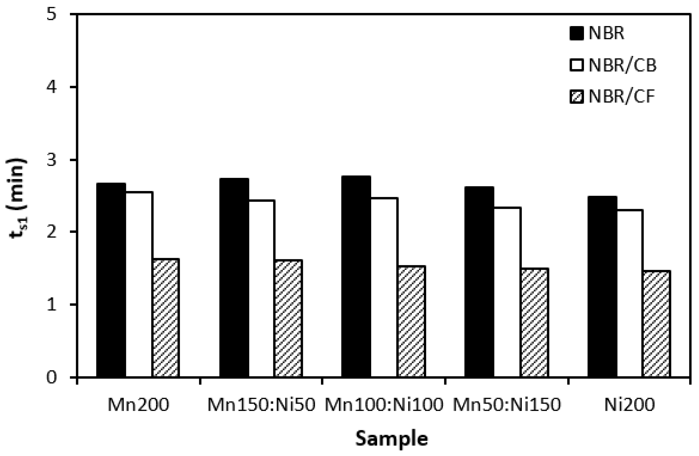
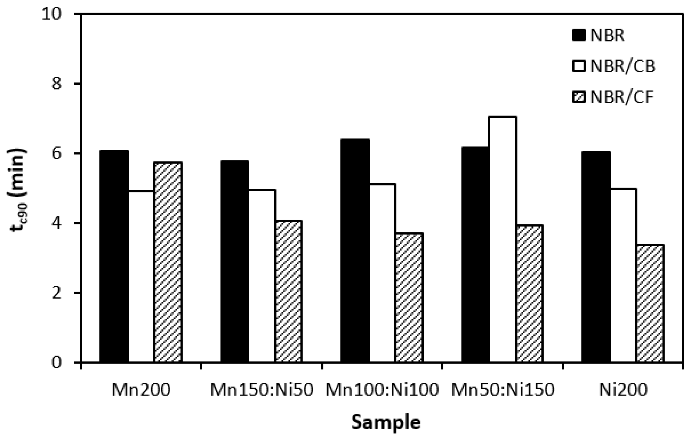
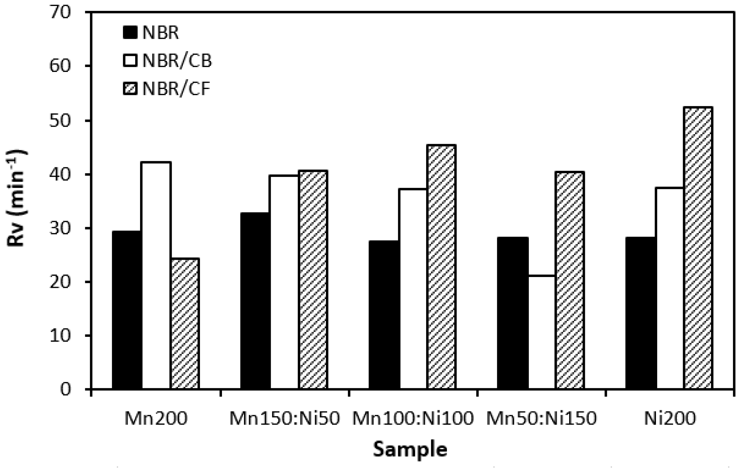
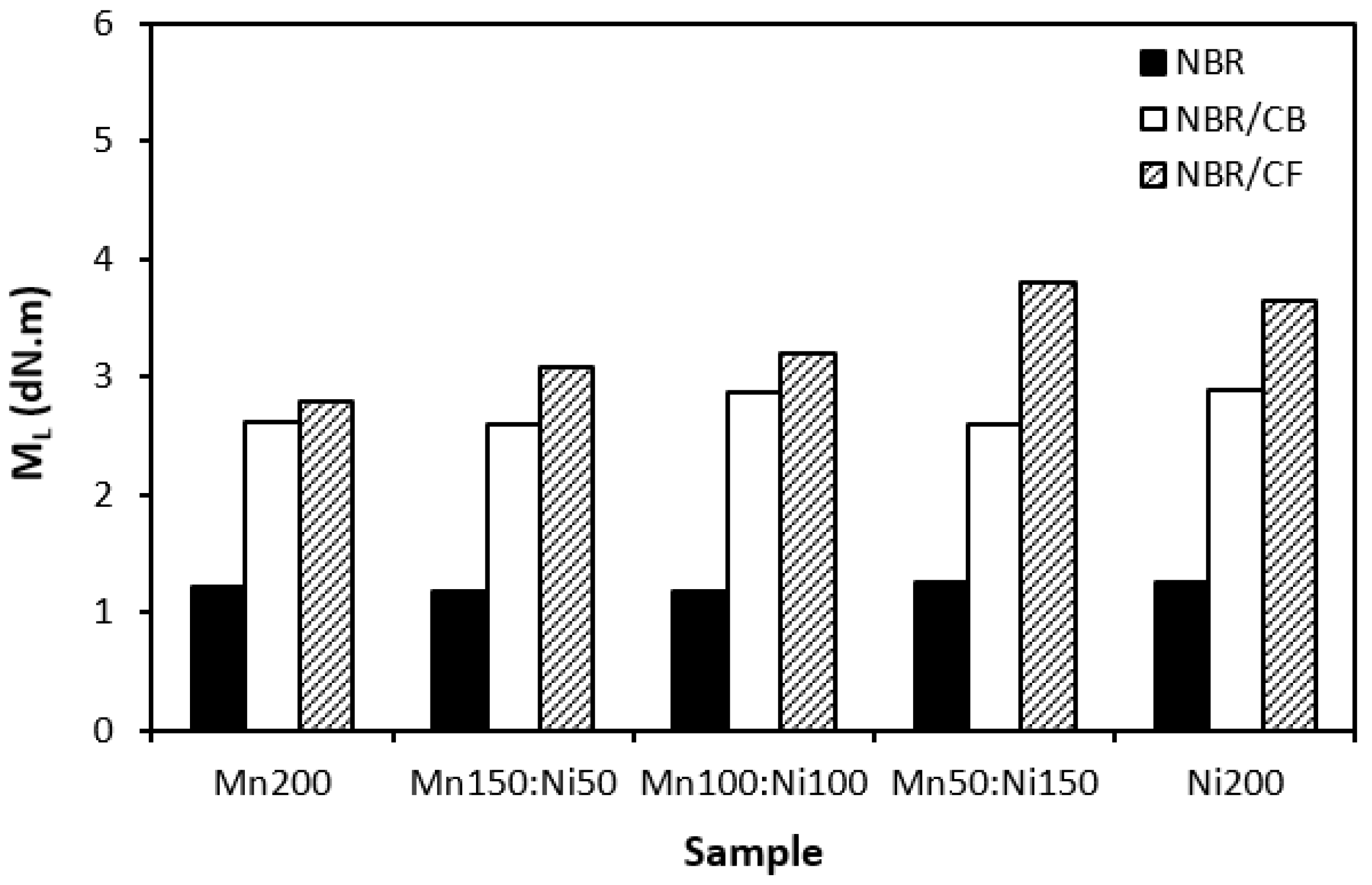
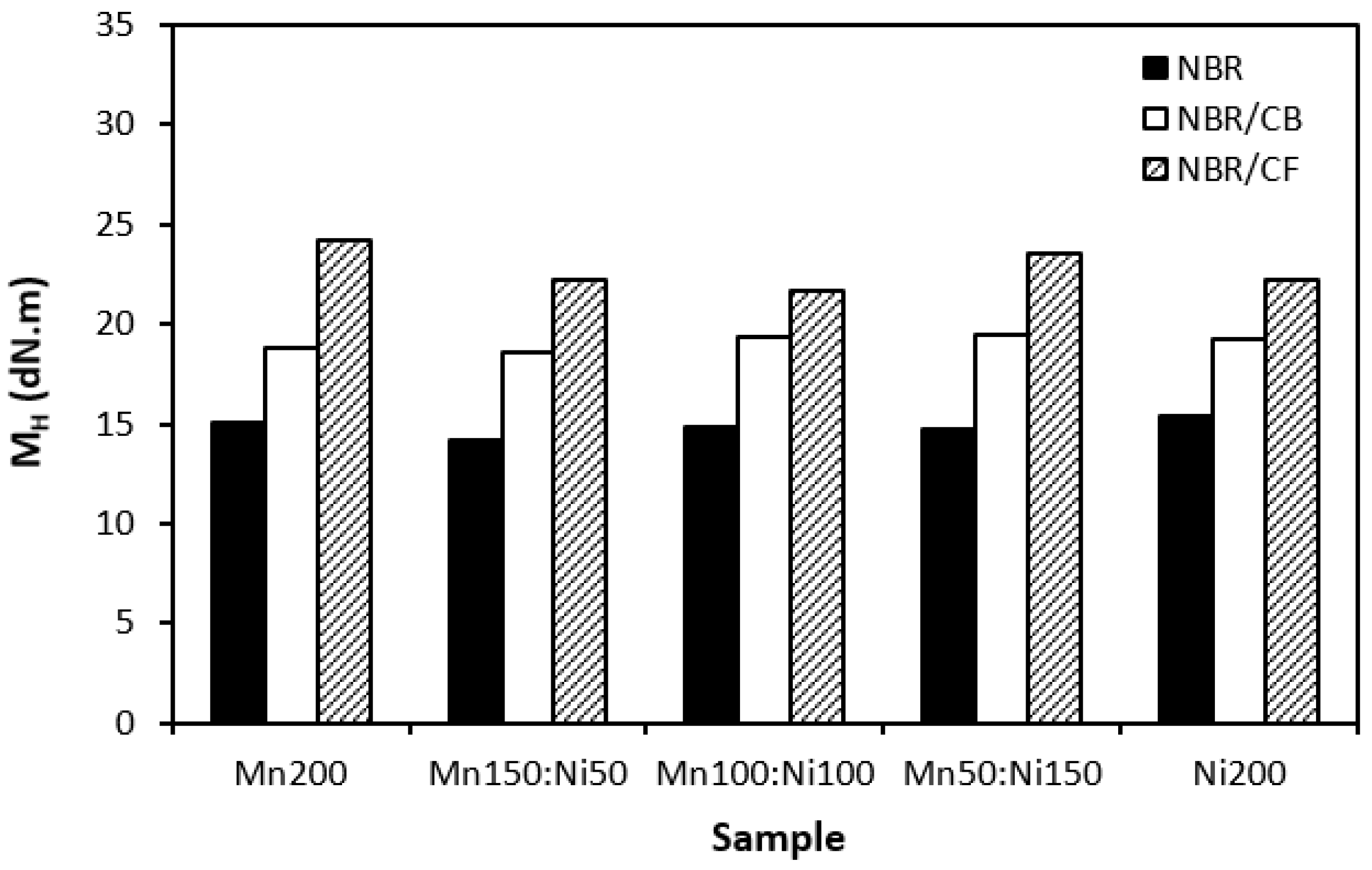
3.1. Curing Process
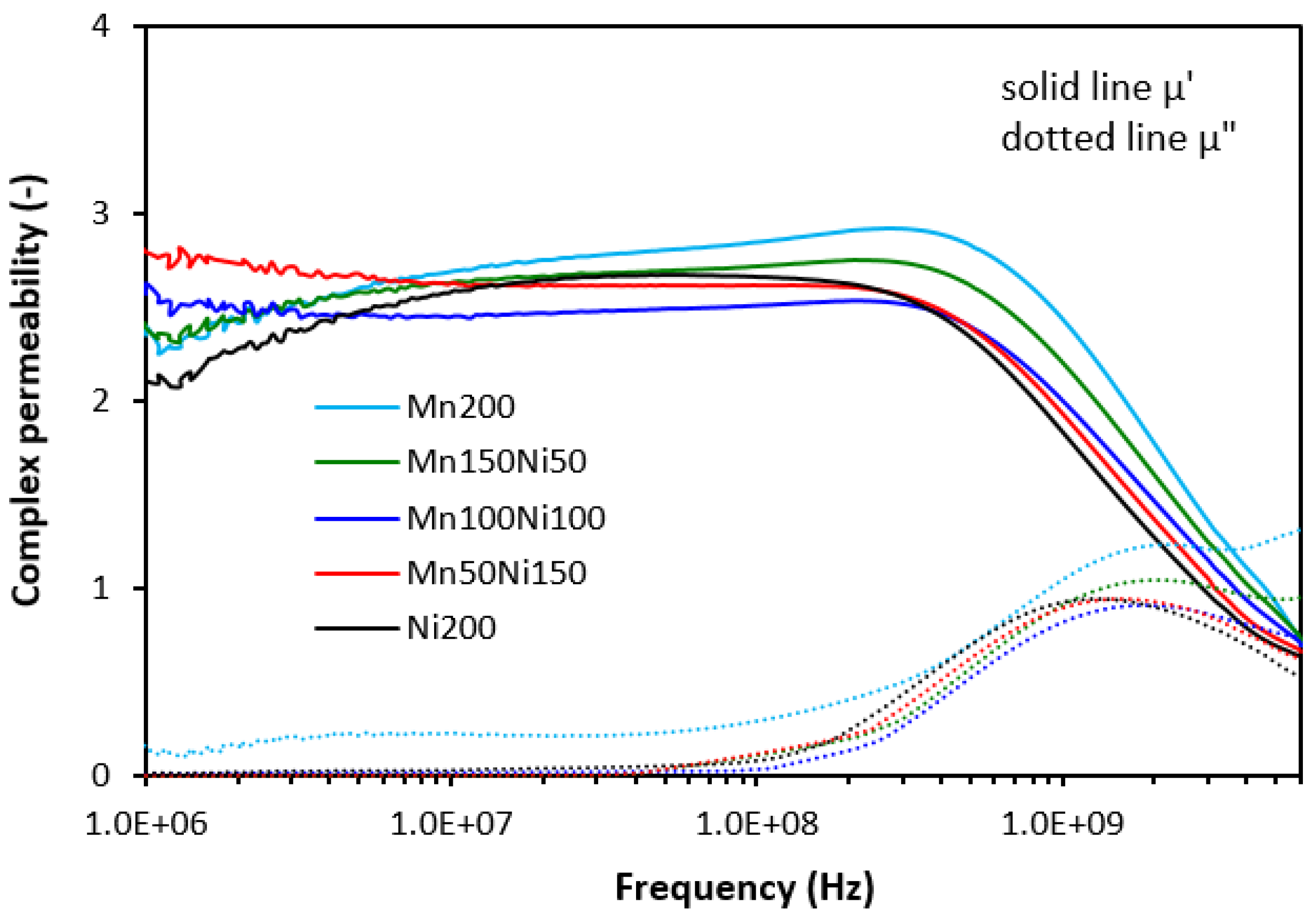
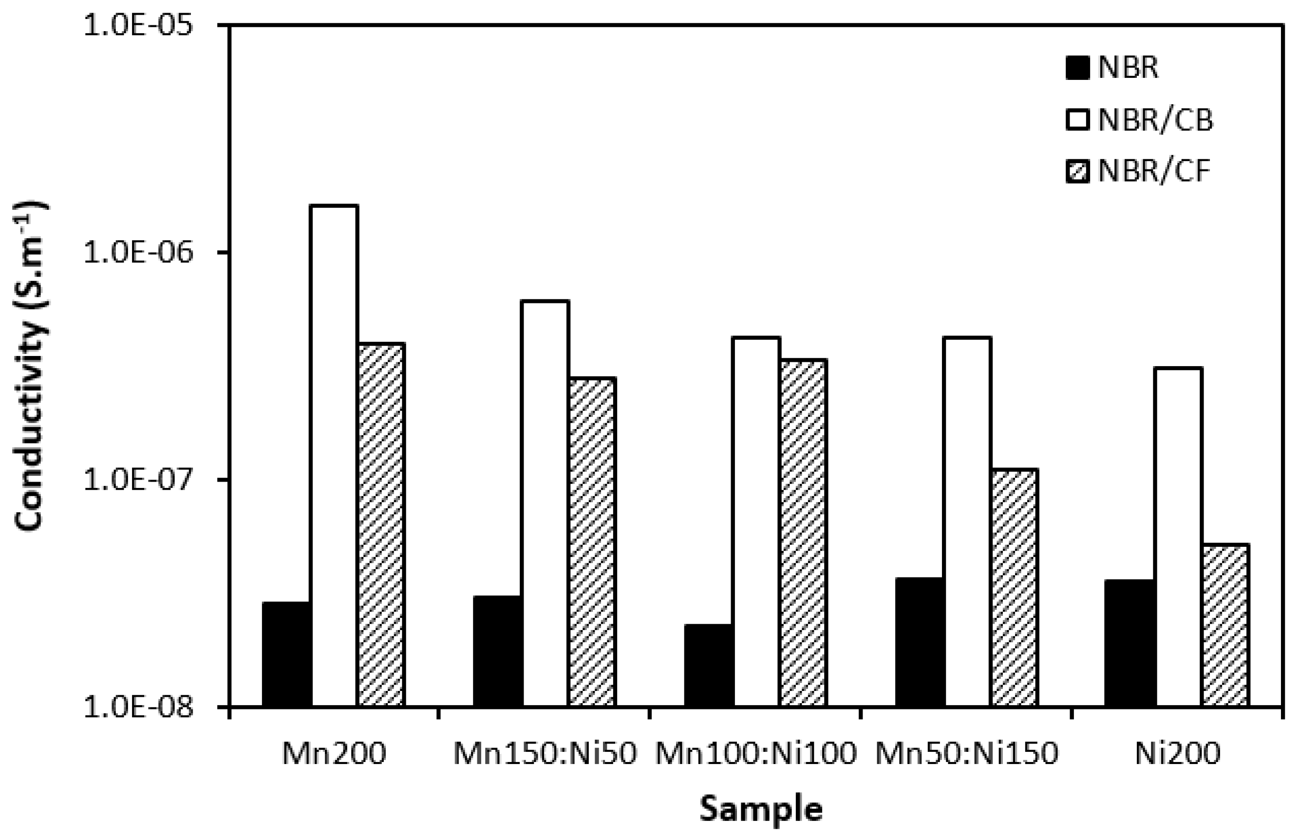
3.2. Electromagnetic Absorption Parameters and Electrical Conductivity
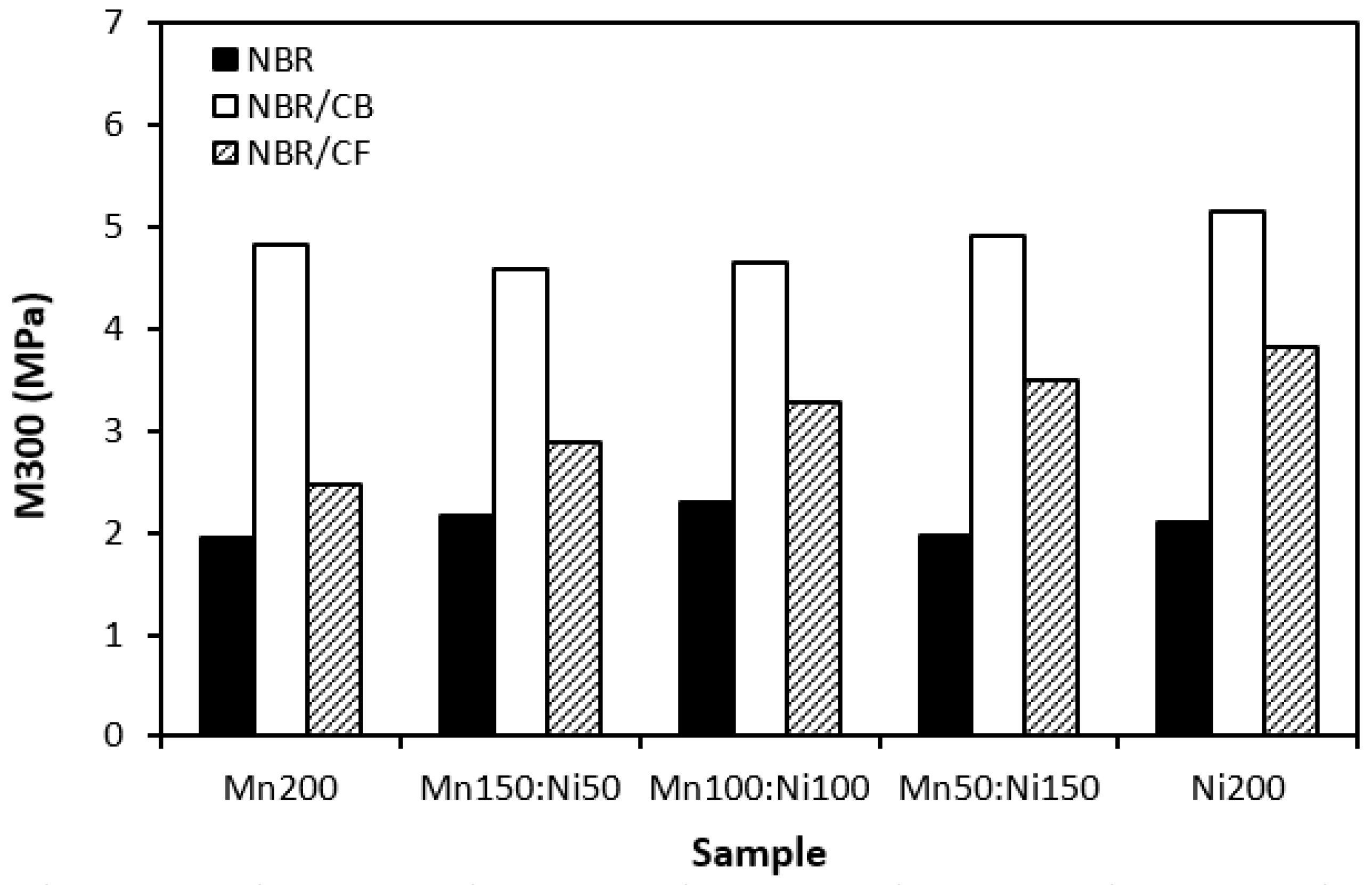
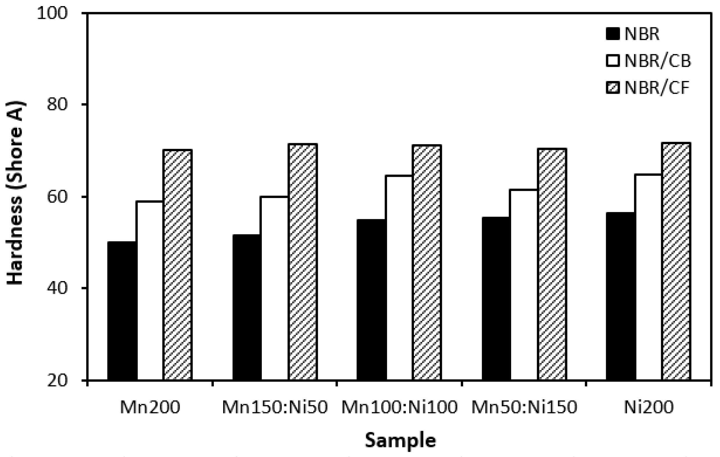
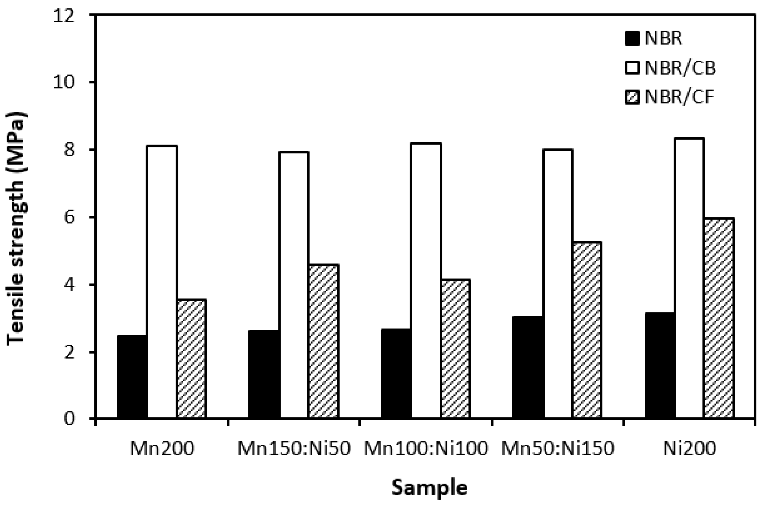
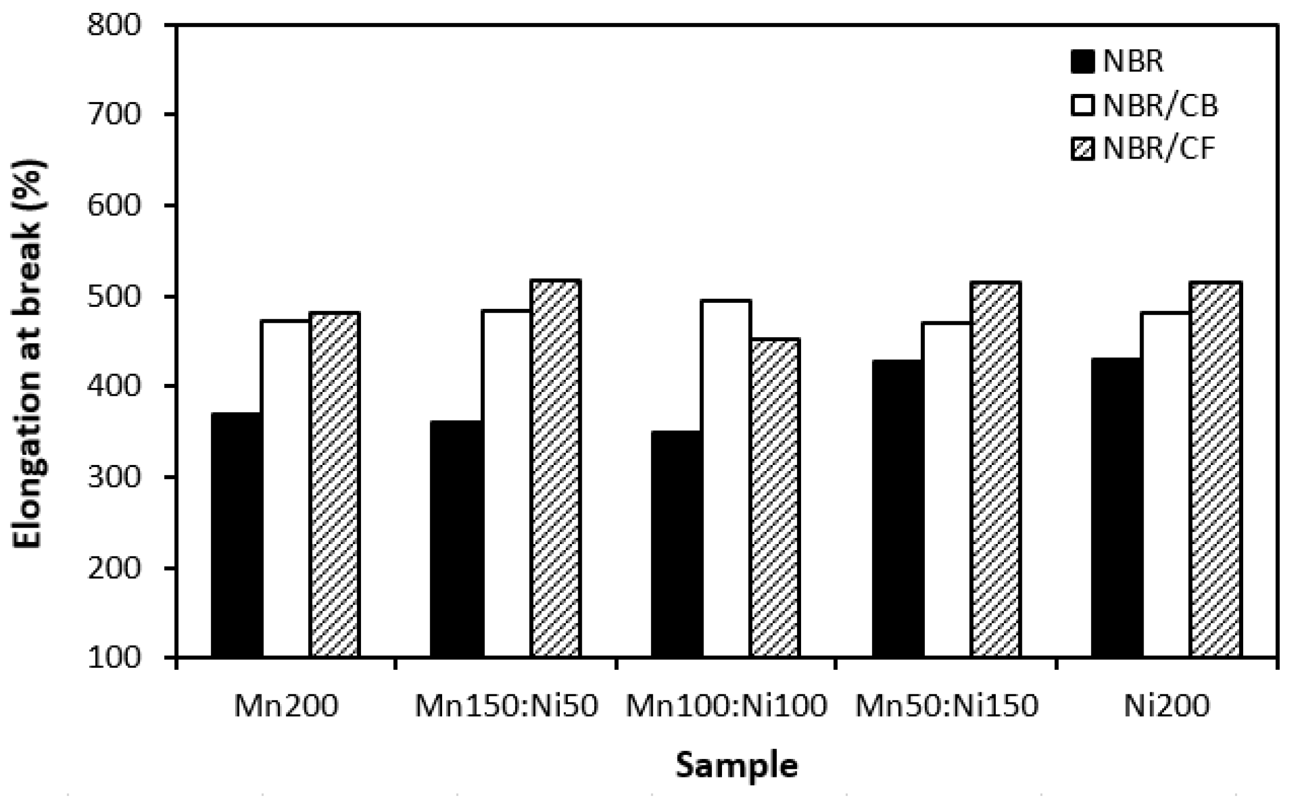
3.3. Physical–Mechanical Characteristics
4. Conclusions
Author Contributions
Funding
Institutional Review Board Statement
Data Availability Statement
Conflicts of Interest
References
- Hu, C.; Zuo, H.; Li, Y. Effects of radiofrequency electromagnetic radiation on neurotransmitters in the brain. Front. Public Health 2021, 9, 691880. [Google Scholar] [CrossRef]
- Apakuppakul, S.; Methachittiphan, N.; Apiyasawat, S. Effect of electromagnetic interference from smartphone on cardiac implantable electronic device (EMI-PHONE study). J. Arrhythm. 2022, 38, 778–782. [Google Scholar] [CrossRef]
- Deutschmann, B.; Winkler, O.V.E.G.; Kastner, P. Impact of electromagnetic interference on the functional safety of smart power devices for automotive applications. Elektrotech. Inf. Tech. 2018, 135, 352–359. [Google Scholar] [CrossRef]
- Kaszuba-Zwoińska, J.; Gremba, J.; Gałdzińska-Calik, B.; Wójcik-Piotrowicz, K.; Thor, P.J. Electromagnetic field induced biological effects in humans. Przegl. Lek. 2015, 72, 636–641. [Google Scholar]
- Kim, D.K.; Han, W.; Kim, K.W.; Kim, B.J. Electromagnetic interference shielding effectiveness of direct-grown-carbon nanotubes/carbon and glass fiber-reinforced epoxy matrix composites. Materials 2023, 16, 2604. [Google Scholar] [CrossRef]
- Kausar, A.; Ahmad, I.; Zhao, T.; Aldaghri, O.; Ibnaouf, K.H.; Eisa, M.H.; Lam, T.D. Graphene nanocomposites for electromagnetic interference shielding—Trends and advancements. J. Compos. Sci. 2023, 7, 384. [Google Scholar] [CrossRef]
- Gümüş, E.; Yaǧımlı, M.; Arca, E. Investigation of the dielectric properties of graphite and carbon black-filled composites as electromagnetic interference shielding coatings. Appl. Sci. 2023, 13, 8893. [Google Scholar] [CrossRef]
- Ma, Y.; Zhuang, Y.; Li, C.; Shen, X.; Zhang, L. Improving electromagnetic interference shielding while retaining mechanical properties of carbon fiber-based composites by introducing carbon nanofiber sheet into laminate structure. Polymers 2022, 14, 1658. [Google Scholar] [CrossRef] [PubMed]
- Chang, J.; Zhai, H.; Hu, Z.; Li, J. Ultra-thin metal composites for electromagnetic interference shielding. Compos. B 2022, 246, 110269. [Google Scholar] [CrossRef]
- Shakir, M.F.; Tariq, A.; Rehan, Z.A.; Nawab, Y.; Rashid, I.A.; Afzal, A.; Hamid, U.; Raza, F.; Zubair, K.; Rizwan, M.S.; et al. Effect of nickel-spinal-ferrites on EMI shielding properties of polystyrene/polyaniline blend. SN Appl. Sci. 2020, 2, 706. [Google Scholar] [CrossRef]
- Çakmakçi, N.; Kim, G.; Song, H.; Shin, M.; Jung, Y.; Jeong, Y. Ferrite-decorated ultrathin and lightweight carbon nanotube film for electromagnetic interference shielding. ACS Appl. Nano Mater. 2023, 6, 18229–18237. [Google Scholar] [CrossRef]
- Gao, Q.; Wang, X.; Schubert, D.W.; Liu, X. Review on polymer/MXene composites for electromagnetic interference shielding applications. Adv. Nanocompos. 2024, 1, 52–76. [Google Scholar] [CrossRef]
- Gao, Y.; Wang, Z. Microwave absorption and electromagnetic interference shielding properties of Li-Zn ferrite-carbon nanotubes composite. J. Magn. Magn. Mater. 2021, 528, 167808. [Google Scholar] [CrossRef]
- Huang, Y.; Chen, M.; Xie, A.; Xu, X. Recent advances in design and fabrication of nanocomposites for electromagnetic wave shielding and absorbing. Materials 2021, 14, 4148. [Google Scholar] [CrossRef] [PubMed]
- Xu, H.; Yin, X.; Zhu, M.; Li, M.; Zhang, H.; Wei, H.; Zhang, L.; Cheng, L. Constructing hollow graphene nano-spheres confined in porous amorphous carbon particles for achieving full X band microwave absorption. Carbon 2019, 142, 346–353. [Google Scholar] [CrossRef]
- Barathi Dassan, E.G.; Ab Rahman, A.A.; Zainol Abidin, M.S.; Md Akil, H. Carbon nanotube–reinforced polymer composite for electromagnetic interference application: A review. Nanotechnol. Rev. 2020, 9, 768–788. [Google Scholar] [CrossRef]
- Dalal, J.; Lather, S.; Gupta, A.; Dahiya, S.; Maan, A.S.; Singh, K.; Dhawan, S.K.; Ohlan, A. EMI shielding properties of laminated graphene and PbTiO3 reinforced poly(3,4-ethylenedioxythiophene) nanocomposites. Compos. Sci. Technol. 2018, 165, 222–230. [Google Scholar] [CrossRef]
- Kruželák, J.; Kvasničáková; Hložeková, K.; Hudec, I. Progress in polymers and polymer composites used as efficient materials for EMI shielding. Nanoscale Adv. 2021, 3, 123. [Google Scholar] [CrossRef] [PubMed]
- Pongmuksuwan, P.; Salayong, K.; Lertwiriyaprapa, T.; Kitisatorn, W. Electromagnetic absorption and mechanical properties of natural rubber composites based on conductive carbon black and Fe3O4. Materials 2022, 15, 6532. [Google Scholar] [CrossRef]
- Singh Yadav, R.; Kuřitka, I.; Vilčáková, J.; Machovský, M.; Škoda, D.; Urbánek, P.; Masař, M.; Gořalik, M.; Urbánek, M.; Kalina, L.; et al. Polypropylene nanocomposite filled with spinel ferrite NiFe2O4 nanoparticles and in-situ thermally-reduced graphene oxide for electromagnetic interference shielding application. Nanomaterials 2019, 9, 621. [Google Scholar] [CrossRef]
- Phan, C.H.; Mariatti, M.; Koh, Y.H. Electromagnetic interference shielding performance of epoxy composites filled with multiwalled carbon nanotubes/manganese zinc ferrite hybrid fillers. J. Magn. Magn. Mater. 2016, 401, 472–478. [Google Scholar] [CrossRef]
- Sadek, R.; Sharawi, M.S.; Dubois, C.; Tantawy, H.; Chaouki, J. Reduced graphene oxide/barium ferrite ceramic nanocomposite synergism for high EMI wave absorption. ACS Omega 2023, 8, 15099–15113. [Google Scholar] [CrossRef] [PubMed]
- Kruželák, J.; Kvasničáková, A.; Hložeková, K.; Dosoudil, R.; Gořalík, M.; Hudec, I. Electromagnetic interference shielding and physical-mechanical characteristics of rubber composites filled with manganese-zinc ferrite and carbon black. Polymers 2021, 13, 616. [Google Scholar] [CrossRef] [PubMed]
- Li, Z.W.; Yang, Z.H. The studies of high-frequency magnetic properties and absorption characteristics for amorphous-filler composites. J. Magn. Magn. Mater. 2015, 391, 172–178. [Google Scholar] [CrossRef]
- Alegaonkar, A.P.; Baskey, H.B.; Alegaonkar, P.S. Microwave scattering parameters of ferro–nanocarbon composites for tracking range countermeasures. Mater. Adv. 2022, 3, 1660. [Google Scholar] [CrossRef]
- Pawar, S.P.; Arjmand, M.; Pötschke, P.; Krause, B.; Fisher, D.; Bose, S.; Sundararaj, U. Tuneable dielectric properties derived from nitrogen-doped carbon nanotubes in PVDF-based nanocomposites. ACS Omega 2018, 3, 9966–9980. [Google Scholar] [CrossRef]
- Koriem, A.A.; Abd El-Aziz, M.E.; Salem, S.R.; Hussain, A.I.; Turky, G. Management of agricultural waste to manufacture biochar: An alternative reinforcing filler for carbon black in nitrile butadiene rubber composites. J. Clean. Prod. 2023, 428, 139360. [Google Scholar] [CrossRef]
- Sarvi, A.; Sundararaj, U. Electrical permitivitty and electrical conductivity of multiwalled carbon nanotube-polyaniline (MWCNT-PANi) core-shell nanofibres and MWCNT-PANi/polystyrene composites. Macromol. Mater. Eng. 2014, 299, 1013–1020. [Google Scholar] [CrossRef]
- Yadav, R.S.; Kuřitka, I.; Vilcakova, J.; Machovsky, M.; Skoda, D.; Urbánek, P.; Masař, M.; Jurča, M.; Urbánek, M.; Kalina, L.; et al. NiFe2O4 nanoparticles synthesized by dextrin from corn-mediated sol-gel combustion method and its polypropylene nanocomposites engineered with reduced graphene oxide for the reduction of electromagnetic pollution. ACS Omega 2019, 4, 22069–22081. [Google Scholar] [CrossRef] [PubMed]
- Petrossian, G.; Aliheidari, N.; Ameli, A. Thermoplastic polyurethane/lead zirconate titanate/carbon nanotube composites with very high dielectric permittivity and low dielectric loss. J. Compos. Sci. 2020, 4, 137. [Google Scholar] [CrossRef]
- Zachariah, S.M.; Antony, T.; Grohens, Y.; Thomas, S. From waste to wealth: A critical review on advanced materials for EMI shielding. J. Appl. Polym. Sci. 2022, 139, e52974. [Google Scholar] [CrossRef]
- Naghdi, S.; Jaleh, B.; Eslamipanah, M.; Moradi, A.; Abdollahi, M.; Einali, N.; Rhee, K.Y. Graphene family, and their hybrid structures for electromagnetic interference shielding applications: Recent trends and prospects. J. Alloys Compd. 2022, 900, 163176. [Google Scholar] [CrossRef]
- Kruželák, J.; Kvasničáková, A.; Hložeková, K.; Plavec, R.; Dosoudil, R.; Gořalík, M.; Vilčáková, J.; Hudec, I. Mechanical, thermal, electrical characteristics and EMI absorption shielding effectiveness of rubber composites based on ferrite and carbon fillers. Polymers 2021, 13, 2937. [Google Scholar] [CrossRef] [PubMed]
- Li, M.; Zhao, Y.; Zhang, M.; Jiang, S.; Farooq, A.; Liu, L.; Ge, A.; Liu, L. Recent progress in the application of cellulose in electromagnetic interference shielding materials. Macromol. Mater. Eng. 2022, 307, 2100899. [Google Scholar] [CrossRef]
- Chen, W.; Wang, J.; Zhang, B.; Wu, Q.; Su, X. Enhanced electromagnetic interference shielding properties of carbon fiber veil/Fe3O4 nanoparticles/epoxy multiscale composites. Mater. Res. Express 2017, 4, 126303. [Google Scholar] [CrossRef]
- Xu, L.; Wan, S.; Heng, Y.; Wang, S.; Yang, J.; Dong, Y.; Fu, Y.; Ni, Q. Double layered design for electromagnetic interference shielding with ultra-low reflection features: PDMS including carbon fibre on top and graphene on bottom. Compos. Sci. Technol. 2023, 231, 109797. [Google Scholar] [CrossRef]


| Filler | Particle Size Distribution | D10 | D50 |
|---|---|---|---|
| MnZn ferrite | 0.7–50 µm | 4.7 µm | 16.3 µm |
| NiZn ferrite | 0.2–70 µm | 3.0 µm | 21.4 µm |
| NBR | 100 | 100 | 100 | 100 | 100 |
| ZnO | 3 | 3 | 3 | 3 | 3 |
| stearic acid | 2 | 2 | 2 | 2 | 2 |
| CBS | 1.5 | 1.5 | 1.5 | 1.5 | 1.5 |
| sulfur | 1.5 | 1.5 | 1.5 | 1.5 | 1.5 |
| MnZn ferrite | 200 | 150 | 100 | 50 | 0 |
| NiZn ferrite | 0 | 50 | 100 | 150 | 200 |
| designation | Mn200 | Mn150 | Mn100 | Mn50 | Ni200 |
| Ni50 | Ni100 | Ni150 |
| NBR | 100 | 100 | 100 | 100 | 100 |
| ZnO | 3 | 3 | 3 | 3 | 3 |
| stearic acid | 2 | 2 | 2 | 2 | 2 |
| CBS | 1.5 | 1.5 | 1.5 | 1.5 | 1.5 |
| sulfur | 1.5 | 1.5 | 1.5 | 1.5 | 1.5 |
| CB or CF | 25 | 25 | 25 | 25 | 25 |
| MnZn ferrite | 200 | 150 | 100 | 50 | 0 |
| NiZn ferrite | 0 | 50 | 100 | 150 | 200 |
| designation | CB, CF-Mn200 | CB, CF-Mn150 | CB, CF-Mn100 | CB, CF-Mn50 | CB, CF-Ni200 |
| Ni50 | Ni100 | Ni150 |
| Sample | RLmin(dB) | fm(MHz) | Δf (MHz) −10 dB | Δf (MHz) −20 dB |
|---|---|---|---|---|
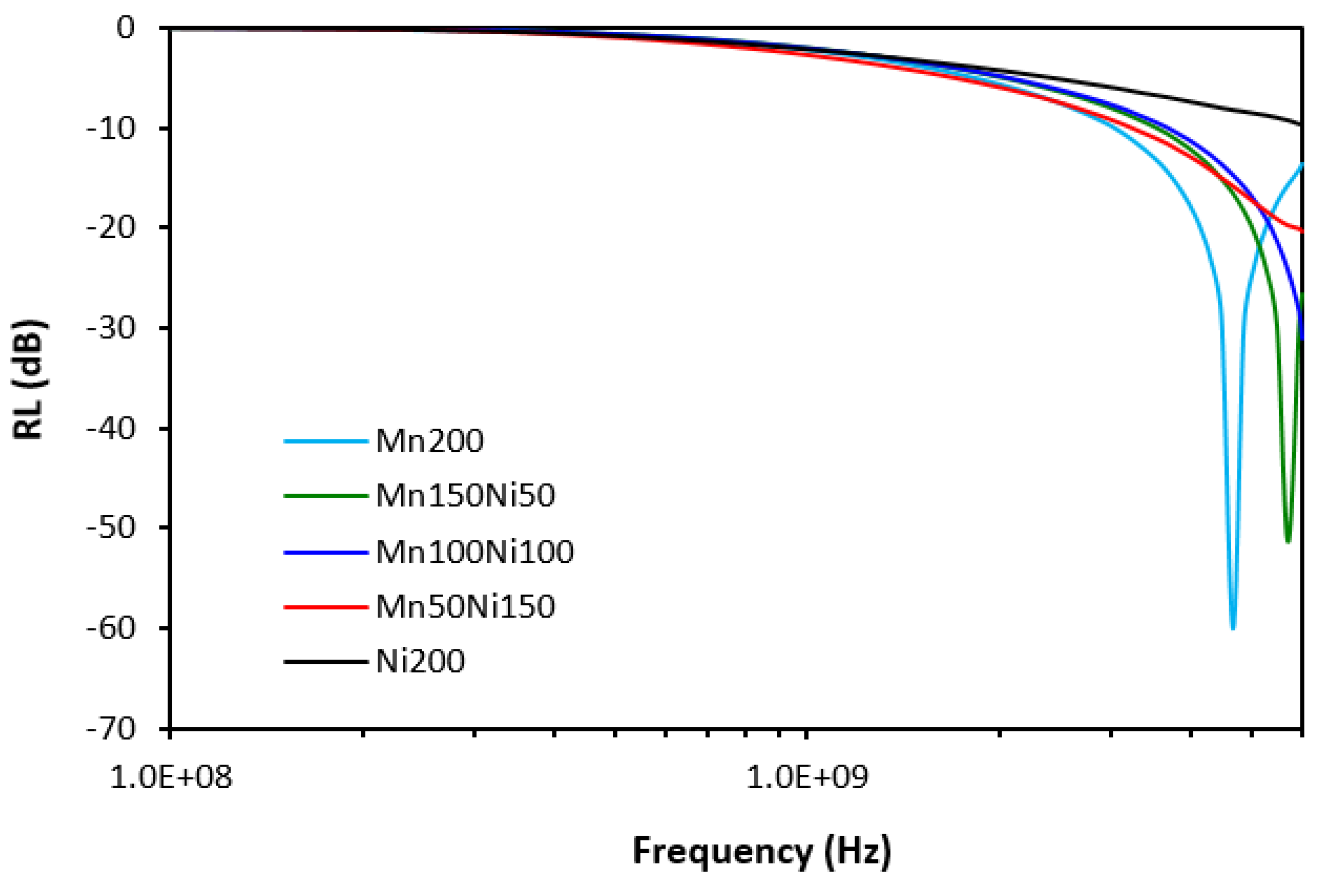
| Mn200 | −60.1 | 4670 | 2950 | 1100 |
| Mn150Ni50 | −51.4 | 5700 | 2450 | 980 |
| Mn100Ni100 | −31.1 | 6000 | 2300 | 630 |
| Mn50Ni150 | 20.3 | 6000 | 2800 | 200 |
| Ni200 | −9.7 | 6000 | - | - |
| Sample | RLmin(dB) | fm(MHz) | Δf (MHz) −10 dB | Δf (MHz) −20 dB |
|---|---|---|---|---|
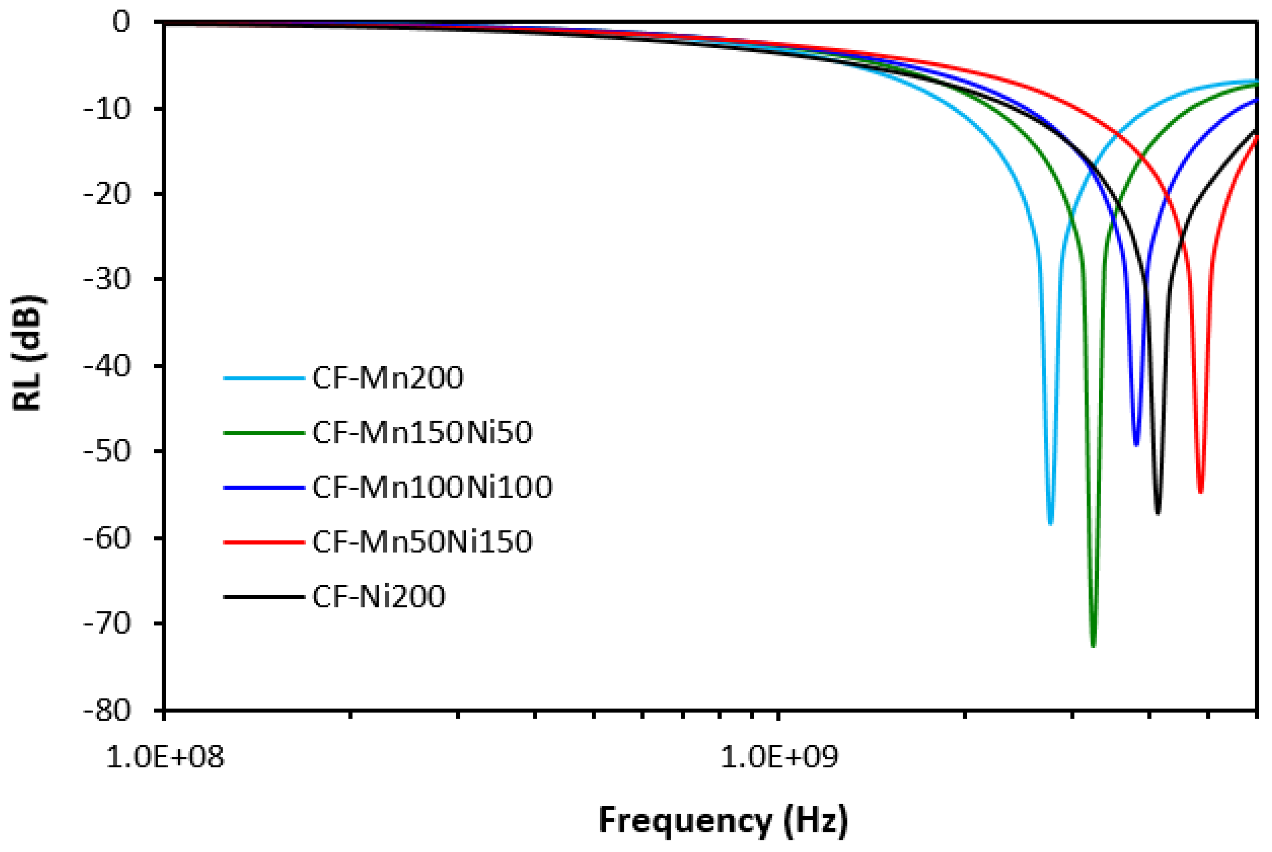
| CF-Mn200 | −58.3 | 2769 | 2130 | 600 |
| CF-Mn150Ni50 | −72.6 | 3250 | 2500 | 720 |
| CF-Mn100Ni100 | −49.2 | 3820 | 3140 | 900 |
| CF-Mn50Ni150 | −54.8 | 4860 | 2980 | 1130 |
| CF-Ni200 | −57.0 | 4140 | 3600 | 1380 |
| Sample | RLmin(dB) | fm(MHz) | Δf (MHz) −10 dB | Δf (MHz) −20 dB |
|---|---|---|---|---|
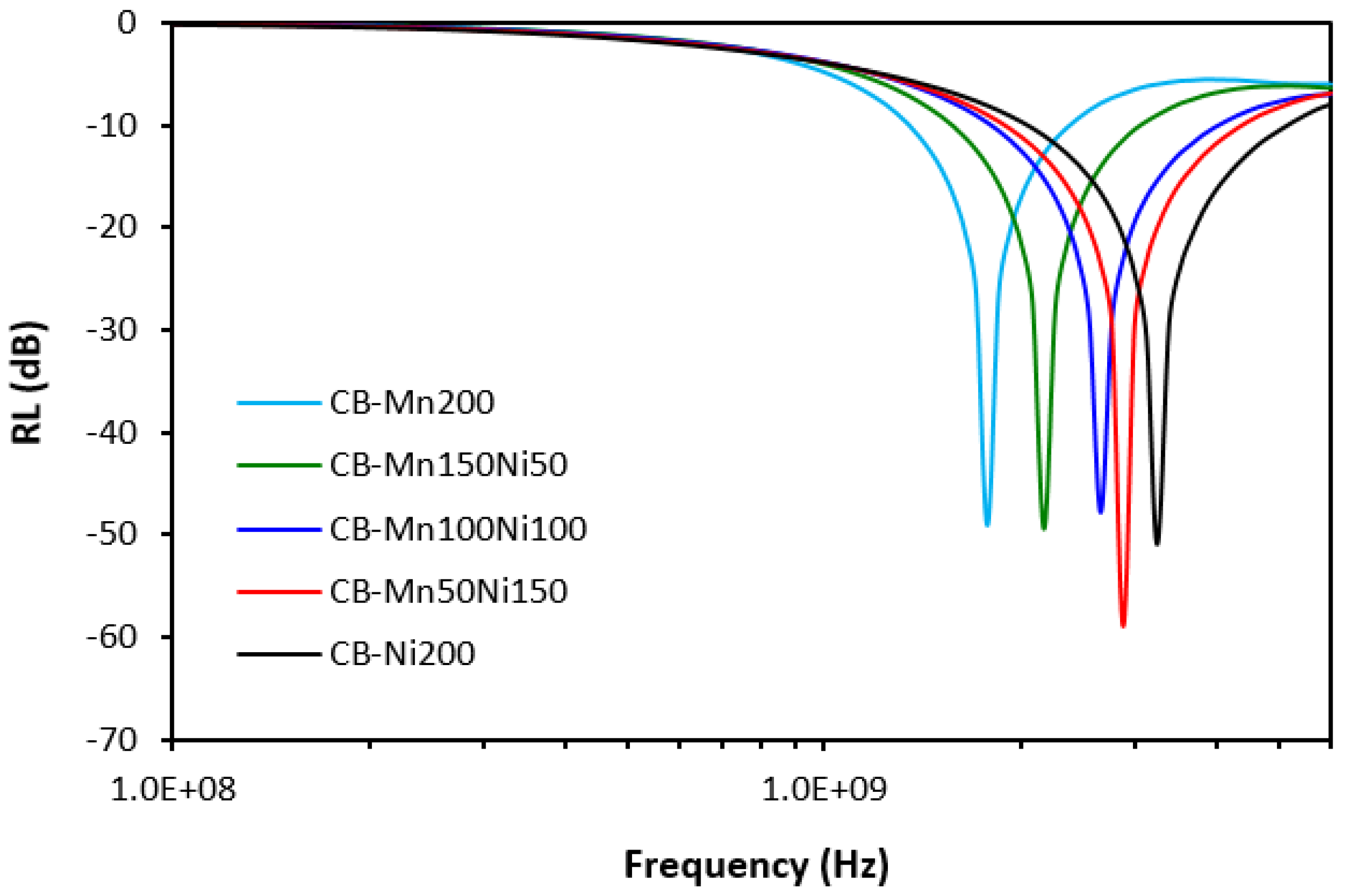
| CB-Mn200 | −49.0 | 1780 | 1060 | 300 |
| CB-Mn150Ni50 | −49.5 | 2180 | 1500 | 430 |
| CB-Mn100Ni100 | −47.8 | 2660 | 2240 | 600 |
| CB-Mn50Ni150 | −59.0 | 2880 | 2500 | 700 |
| CB-Ni200 | −51.0 | 3250 | 3100 | 880 |
Disclaimer/Publisher’s Note: The statements, opinions and data contained in all publications are solely those of the individual author(s) and contributor(s) and not of MDPI and/or the editor(s). MDPI and/or the editor(s) disclaim responsibility for any injury to people or property resulting from any ideas, methods, instructions or products referred to in the content. |
© 2024 by the authors. Licensee MDPI, Basel, Switzerland. This article is an open access article distributed under the terms and conditions of the Creative Commons Attribution (CC BY) license (https://creativecommons.org/licenses/by/4.0/).
Share and Cite
Kruželák, J.; Kvasničáková, A.; Džuganová, M.; Dosoudil, R.; Hudec, I.; Krump, H. The Electrical Conductivity, EMI Absorption Shielding Performance, Curing Process, and Mechanical Properties of Rubber Composites. Polymers 2024, 16, 566. https://doi.org/10.3390/polym16050566
Kruželák J, Kvasničáková A, Džuganová M, Dosoudil R, Hudec I, Krump H. The Electrical Conductivity, EMI Absorption Shielding Performance, Curing Process, and Mechanical Properties of Rubber Composites. Polymers. 2024; 16(5):566. https://doi.org/10.3390/polym16050566
Chicago/Turabian StyleKruželák, Ján, Andrea Kvasničáková, Michaela Džuganová, Rastislav Dosoudil, Ivan Hudec, and Henrich Krump. 2024. "The Electrical Conductivity, EMI Absorption Shielding Performance, Curing Process, and Mechanical Properties of Rubber Composites" Polymers 16, no. 5: 566. https://doi.org/10.3390/polym16050566
APA StyleKruželák, J., Kvasničáková, A., Džuganová, M., Dosoudil, R., Hudec, I., & Krump, H. (2024). The Electrical Conductivity, EMI Absorption Shielding Performance, Curing Process, and Mechanical Properties of Rubber Composites. Polymers, 16(5), 566. https://doi.org/10.3390/polym16050566