
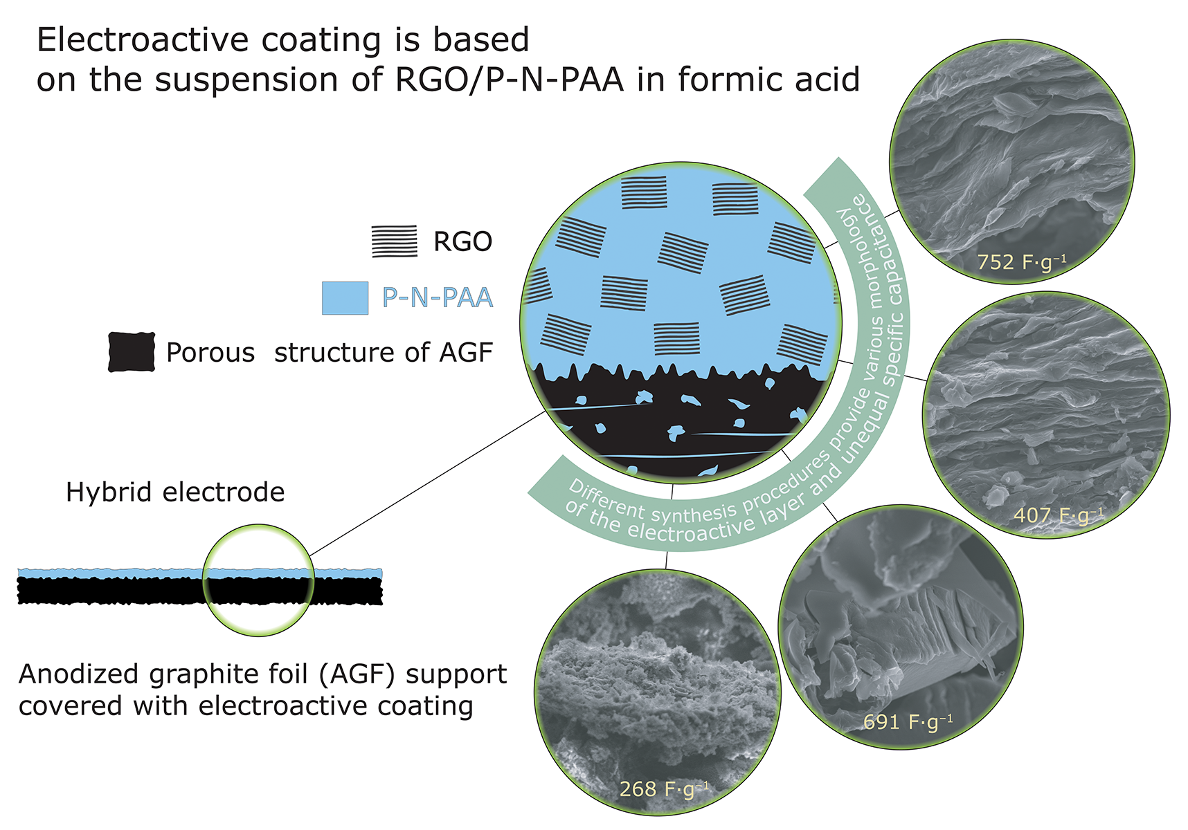
Advanced Electrode Coatings Based on Poly-N-Phenylanthranilic Acid Composites with Reduced Graphene Oxide for Supercapacitors

 , ,
, , 
Abstract

1. Introduction
2. Experimental
2.1. Materials
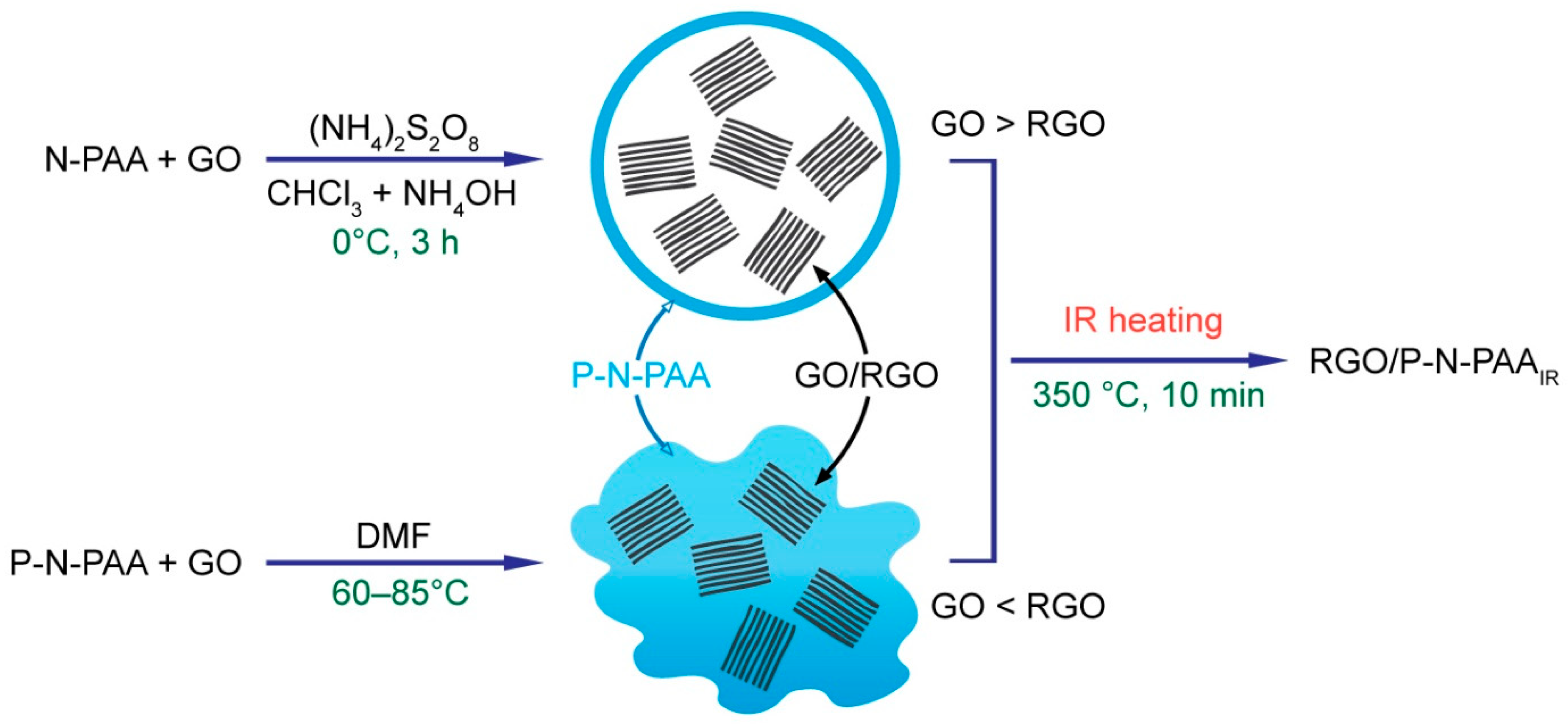
2.2. Synthesis of RGO/P-N-PAA
2.3. Post-Reduction of Graphene Oxide in the RGO/P-N-PAA Composites
2.4. Electrode Preparation
2.5. Electrochemical Measurements
2.6. Materials Characterization
3. Results and Discussion
3.1. Synthesis and Characterization of RGO/P-N-PAA Composites for Electrode Coatings
3.2. Characterization of Hybrid Electrodes
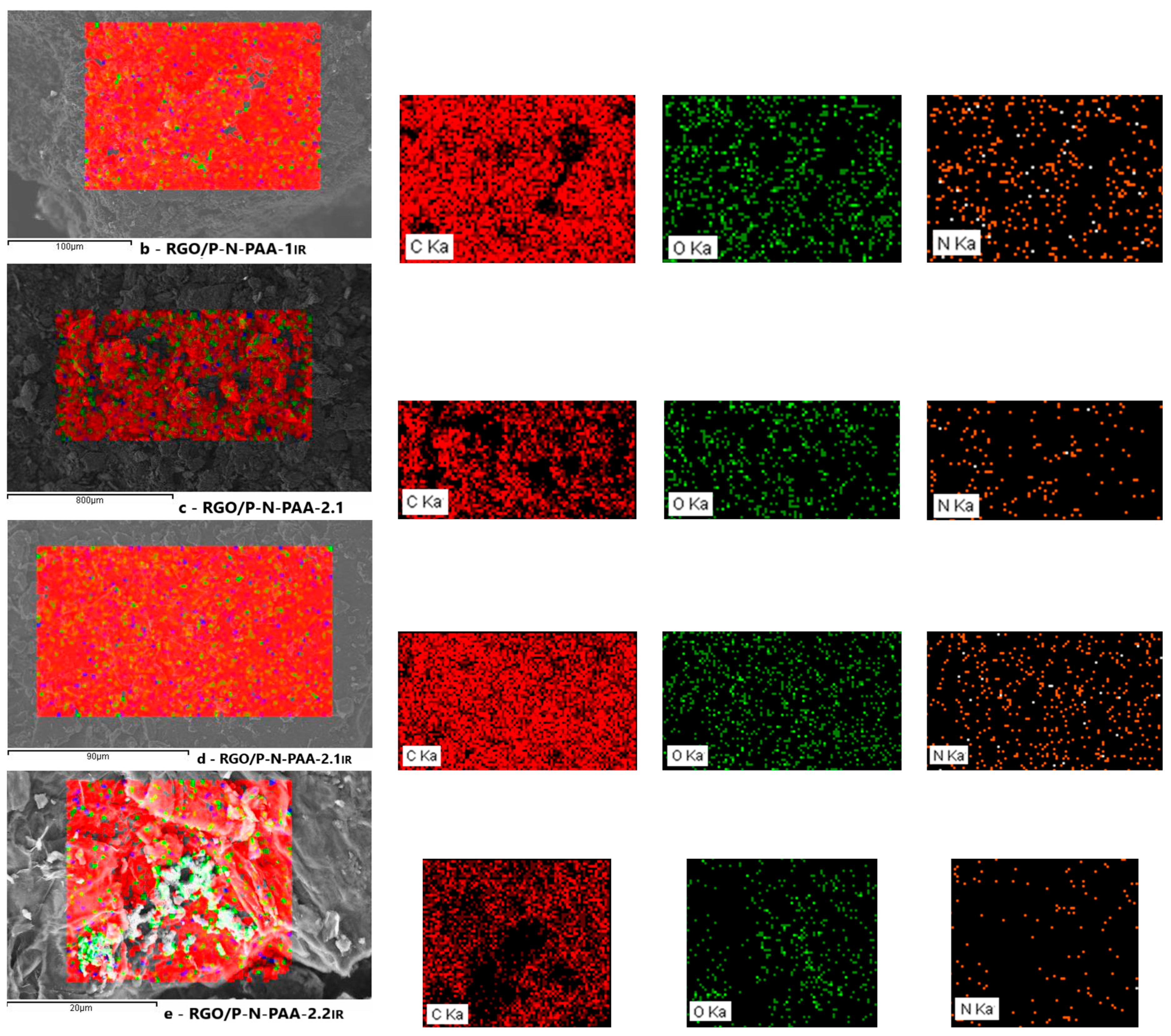
3.2.1. Morphology of Hybrid Electrodes
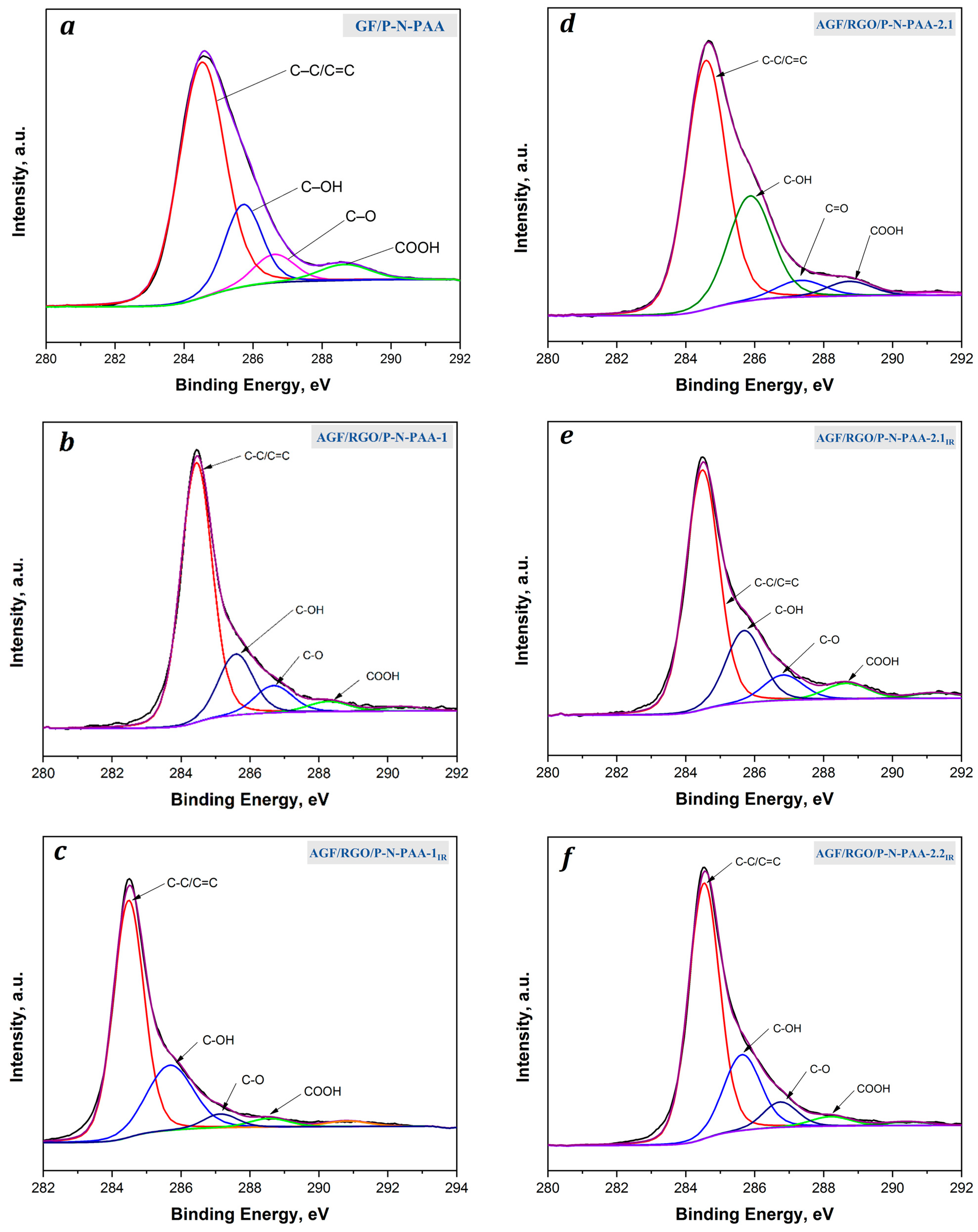
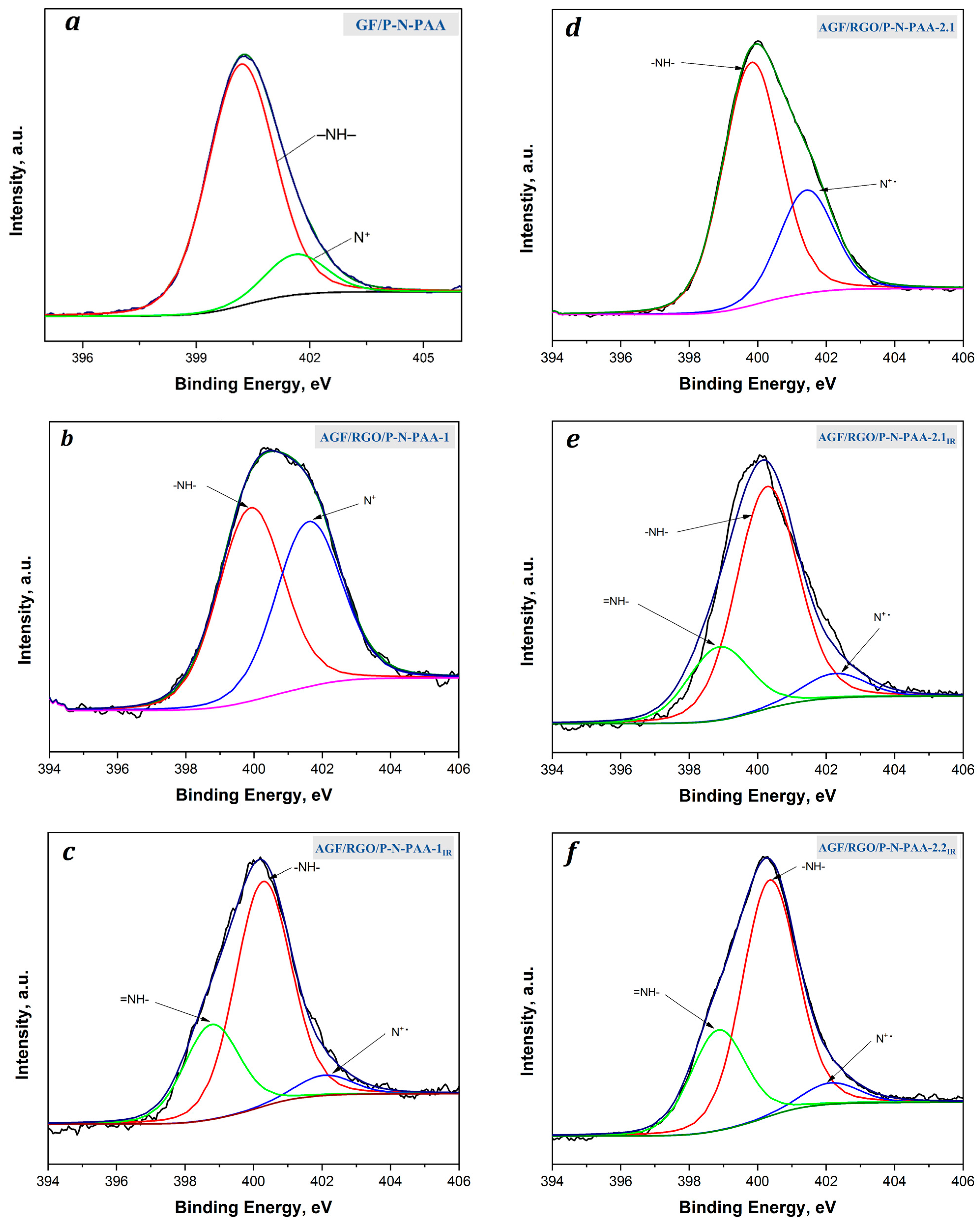
3.2.2. XPS Studies of Hybrid Electrodes
3.3. Electrochemical Behavior of Hybrid Electrodes
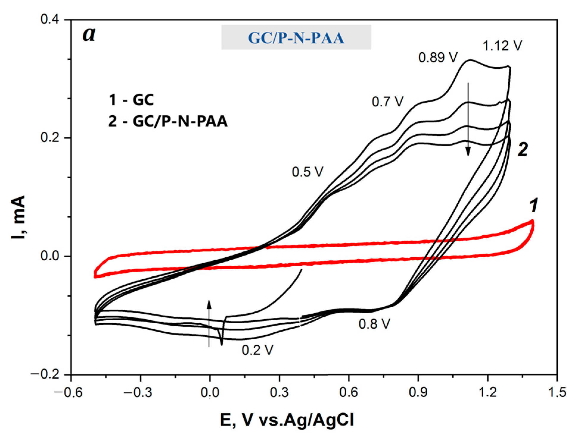
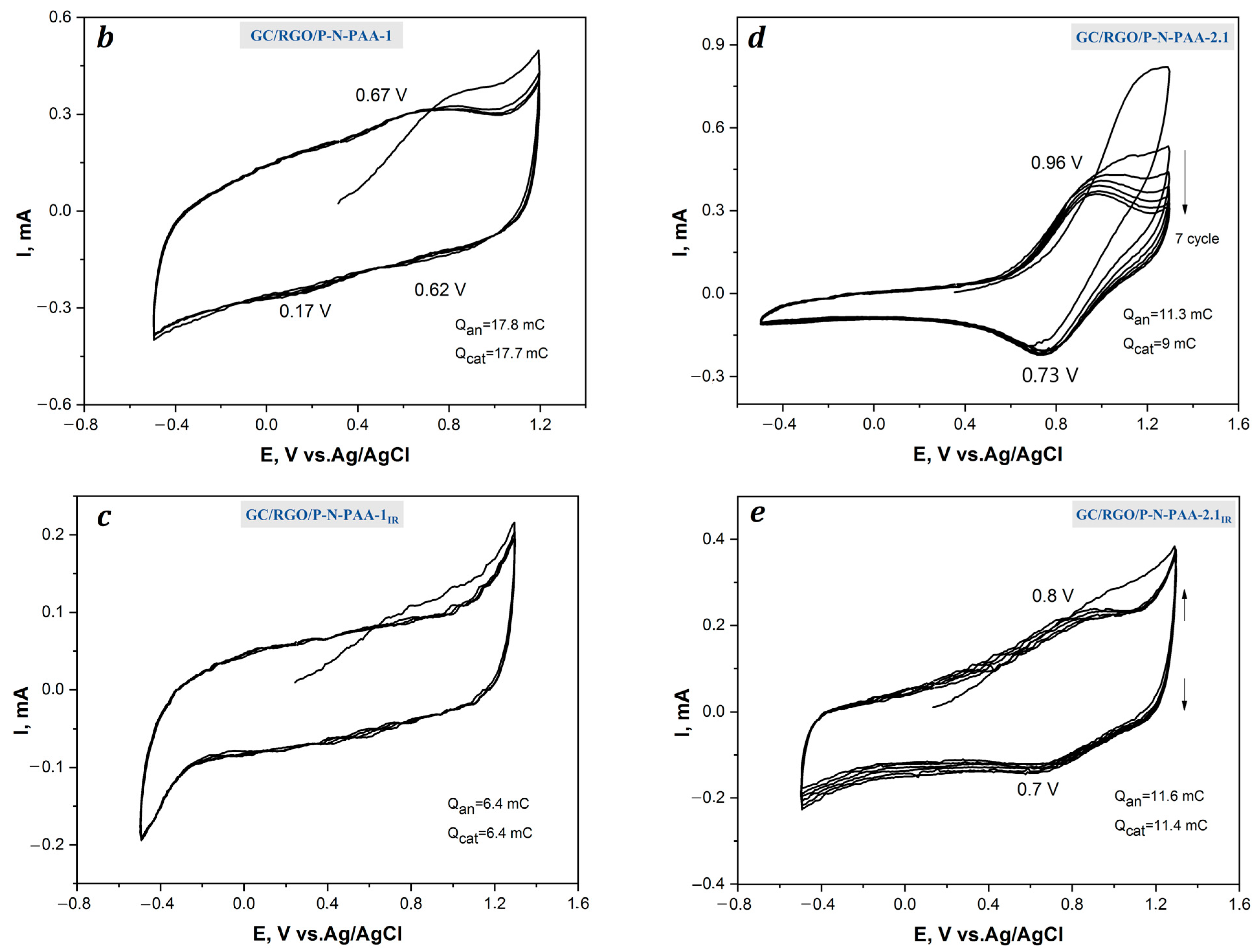
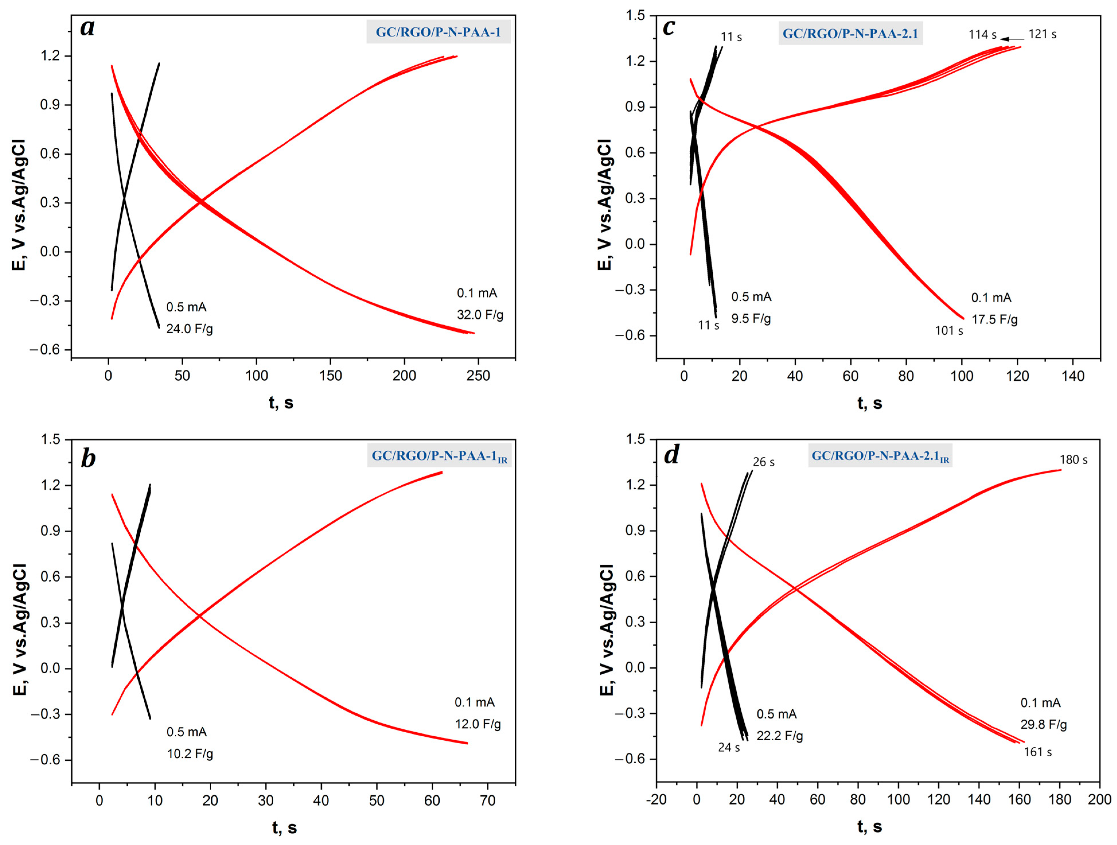
3.3.1. Electrochemical Behavior of GC/RGO/P-N-PAA Electrodes in 1 M LiClO4 in Propylene Carbonate
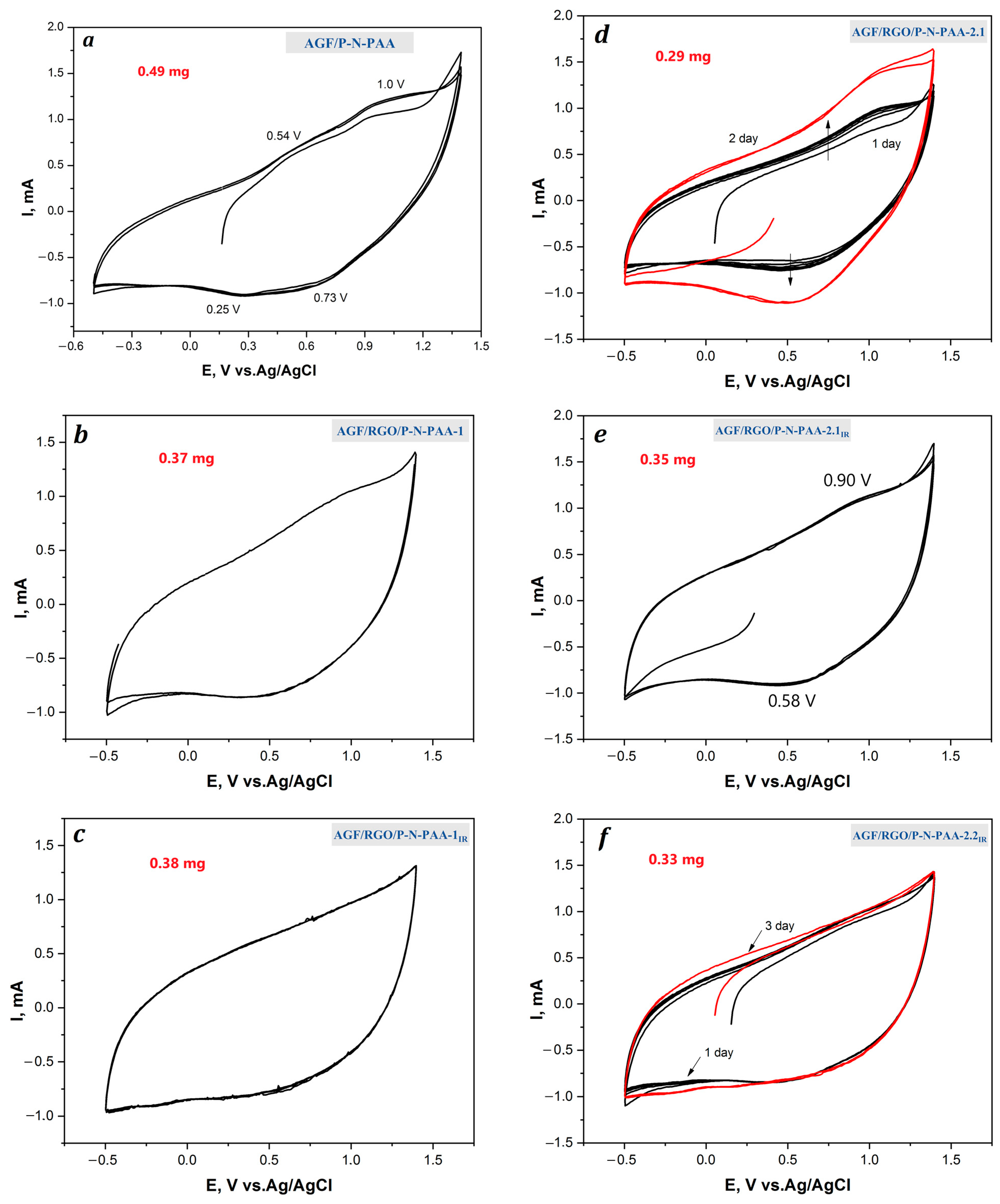
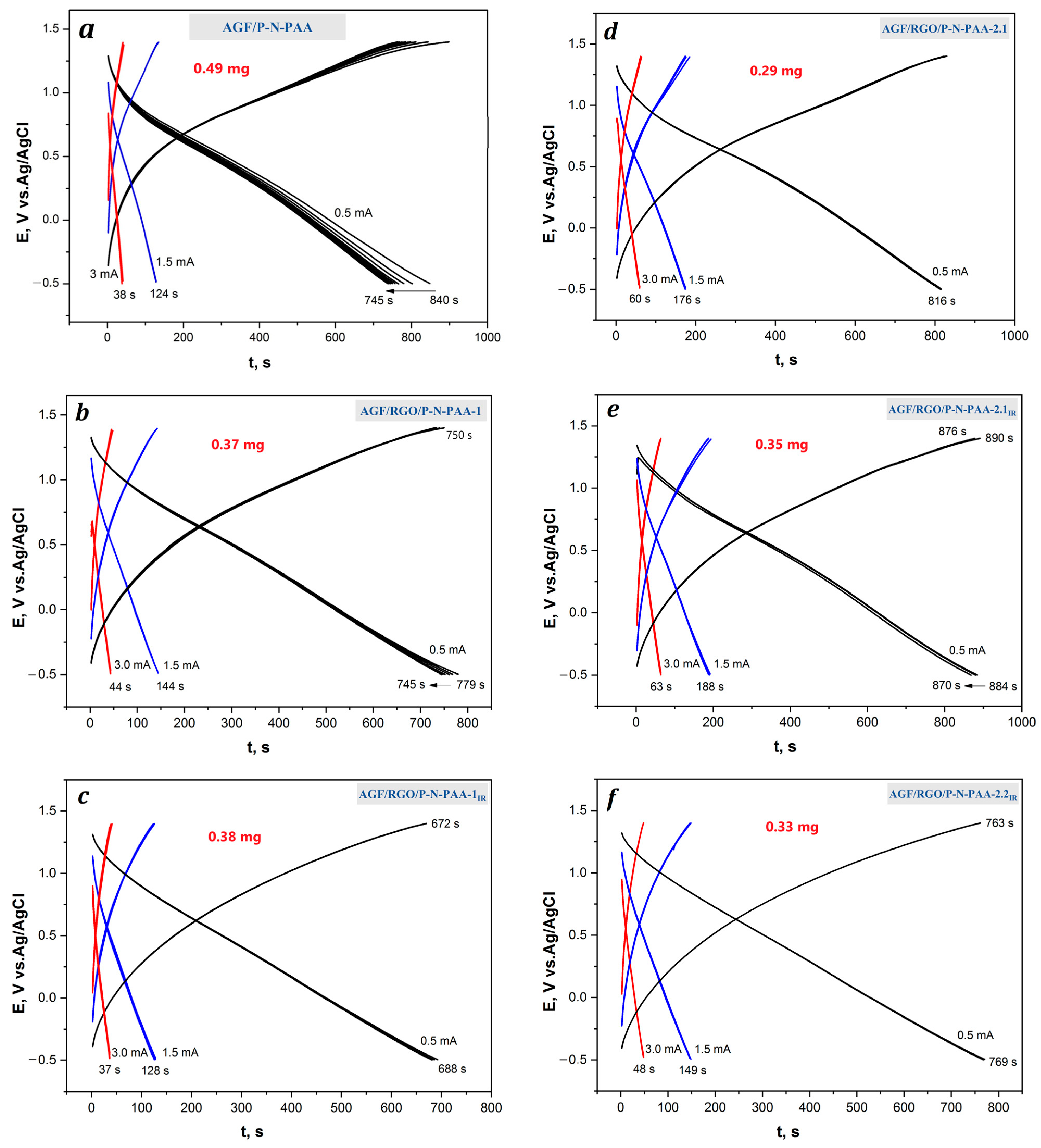
3.3.2. Electrochemical Behavior of AGF/RGO/P-N-PAA Electrodes in 1 M LiClO4 in Propylene Carbonate
4. Conclusions
Author Contributions
Funding
Institutional Review Board Statement
Data Availability Statement
Acknowledgments
Conflicts of Interest
References
- Simon, P.; Gogotsi, Y. Perspectives for electrochemical capacitors and related devices. Nat. Mater. 2020, 19, 1151–1163. [Google Scholar] [CrossRef]
- Hasan, M.A.M.; Wang, Y.; Bowen, C.R.; Yang, Y. 2D Nanomaterials for effective energy scavenging. Nano-Micro Lett. 2021, 13, 82. [Google Scholar] [CrossRef] [PubMed]
- Zhao, Z.; Xia, K.; Hou, Y.; Zhang, Q.; Ye, Z.; Lu, J. Designing flexible, smart and self-sustainable supercapacitors for portable/wearable electronics: From conductive polymers. Chem. Soc. Rev. 2021, 50, 12702–12743. [Google Scholar] [CrossRef] [PubMed]
- Zhang, X.; Jiang, C.; Liang, J.; Wu, W. Electrode materials and device architecture strategies for flexible supercapacitors in wearable energy storage. J. Mater. Chem. A 2021, 9, 8099–8128. [Google Scholar] [CrossRef]
- Wang, F.; Wu, X.; Yuan, X.; Liu, Z.; Zhang, Y.; Fu, L.; Zhu, Y.; Zhou, Q.; Wu, Y.; Huang, W. Latest advances in supercapacitors: From new electrode materials to novel device designs. Chem. Soc. Rev. 2017, 46, 6816–6854. [Google Scholar] [CrossRef] [PubMed]
- González, A.; Goikole, E.; Barren, J.A.; Mysyk, R. Review on supercapacitors: Technologies and materials. Renew. Sustain. Energy Rev. 2016, 58, 1189–1206. [Google Scholar] [CrossRef]
- Lv, H.; Pan, Q.; Song, Y.; Liu, X.-X.; Liu, T. A review on nano-/microstructured materials constructed by electrochemical technologies for supercapacitors. Nano-Micro Lett. 2020, 12, 118. [Google Scholar] [CrossRef] [PubMed]
- Volfkovich, Y.M. Electrochemical supercapacitors (a review). Russ. J. Electrochem. 2021, 57, 311–347. [Google Scholar] [CrossRef]
- Kumar, R.; Joanni, E.; Sahoo, S.; Shim, J.-J.; Tan, W.K.; Matsuda, A.; Singh, R.K. An overview of recent progress in nanostructured carbon-based supercapacitor electrodes: From zero to bi-dimensional materials. Carbon 2022, 193, 298–338. [Google Scholar] [CrossRef]
- Zhang, D.; Tan, C.; Zhang, W.; Pan, W.; Wang, Q.; Li, L. Expanded graphite-based materials for supercapacitors: A Review. Molecules 2022, 27, 716. [Google Scholar] [CrossRef]
- Tong, Z.; Yang, Y.; Wang, J.; Zhao, J.; Su, B.-L.; Yao, L.Y. Layered polyaniline/graphene film from sandwich-structured polyaniline/graphene/polyaniline nanosheets for high-performance pseudosupercapacitors. J. Mater. Chem. A 2014, 2, 4642–4651. [Google Scholar] [CrossRef]
- Sahoo, S.; Kumar, R.; Joann, E.; Singh, R.K.; Shim, J.-S. Advances in pseudocapacitive and battery-like electrode materials for high performance supercapacitors. J. Mater. Chem. A 2022, 10, 13190–13240. [Google Scholar] [CrossRef]
- Chen, J.-J.; Fan, L.-Q.; Wu, Z.-X.; Deng, X.-G.; Tang, T.; Huang, Y.-F.; Wu, J.-H. Phenothiazine/reduced graphene oxide composite as a pseudocapacitive cathode for lithium ion capacitors. Electrochim. Acta 2022, 434, 141340. [Google Scholar] [CrossRef]
- Hong, X.; Zhang, B.; Murphy, E.; Zou, J.; Kim, F. Three-dimensional reduced graphene oxide/polyaniline nanocomposite film prepared by diffusion driven layer-by-layer assembly for high-performance supercapacitors. J. Power Sources 2017, 343, 60–66. [Google Scholar] [CrossRef]
- Zhao, Y.; Liu, C.; Lu, Q.; Ahmad, O.; Pan, X.; Daria, M. Recent progress on freestanding carbon electrodes for flexible supercapacitors. New Carbon Mater. 2022, 37, 875–897. [Google Scholar] [CrossRef]
- Shao, H.; Wu, Y.-C.; Lin, Z.; Tabern, P.-L.; Simon, P. Nanoporous carbon for electrochemical capacitive energy storage. Chem. Soc. Rev. 2020, 49, 3005–3039. [Google Scholar] [CrossRef]
- Ahmad, H.; Khan, R.A.; Koo, B.H.; Alsalme, A. Systematic study of physicochemical and electrochemical properties of carbon nanomaterials. RSC Adv. 2022, 12, 15593–15600. [Google Scholar] [CrossRef]
- Pattanayak, B.; Le, P.-A.; Panda, D.; Simanjuntak, F.M.; Wei, K.-H.; Winie, T.; Tseng, T.-Y. Ion accumulation-induced capacitance elevation in a microporous graphene-based supercapacitor. RSC Adv. 2022, 12, 27082–27093. [Google Scholar] [CrossRef]
- Patra, A.; Namsheer, K.; Jose, J.R.; Sahoo, S.; Chakraborty, B.; Rout, C.S. Understanding the charge storage mechanism of supercapacitors: In situ/operando spectroscopic approaches and theoretical investigations. J. Mater. Chem. A 2021, 9, 25852–25891. [Google Scholar] [CrossRef]
- Rajagopal, S.; Vallikkattil, R.P.; Ibrahim, M.; Velev, D.G. Electrode materials for supercapacitors in hybrid electric vehicles: Challenges and current progress. Condens. Matter. 2022, 7, 6. [Google Scholar] [CrossRef]
- Huang, S.; Li, J.; Zhang, X.; Yang, X.; Wang, L.; Lia, X.; Lü, W. Reduced graphene oxide/polyaniline wrapped carbonized sponge with elasticity for energy storage and pressure sensing. New J. Chem. 2021, 45, 7860–7866. [Google Scholar] [CrossRef]
- Dong, C.; Zhang, X.; Yu, Y.; Huang, L.; Li, J.; Wu, Y.; Liu, Z. An ionic liquid-modified RGO/polyaniline composite for high-performance flexible all-solid-state supercapacitors. Chem. Commun. 2020, 56, 11993–11996. [Google Scholar] [CrossRef] [PubMed]
- Zhang, T.; Yue, H.; Gao, X.; Yao, F.; Chen, H.; Lu, X.; Wanga, Y.; Guo, X. High-performance supercapacitors based on polyaniline nanowire arrays grown on three-dimensional graphene with small pore sizes. Dalton Trans. 2020, 49, 3304–3311. [Google Scholar] [CrossRef]
- Khan, R.; Nishina, Y. Covalent functionalization of carbon materials with redox-active organic molecules for energy storage. Nanoscale 2021, 13, 36–50. [Google Scholar] [CrossRef] [PubMed]
- Velasco, A.; Ryu, Y.K.; Boscá, A.; Ladrón-de-Guevara, A.; Hunt, D.; Zuo, J.; Pedrós, J.; Calle, F.; Martinez, J. Recent trends in graphene supercapacitors: From large area to microsupercapacitors. Sustain. Energy Fuels 2021, 5, 1235–1254. [Google Scholar] [CrossRef]
- Bai, L.; Zhang, Y.; Tong, W.; Sun, L.; Huang, H.; An, Q.; Tian, N.; Chu, P.K. Graphene for energy storage and conversion: Synthesis and interdisciplinary applications. Electrochem. Energy Rev. 2020, 3, 395–430. [Google Scholar] [CrossRef]
- Lin, S.; Tang, J.; Zhang, W.; Zhang, K.; Chen, Y.; Gao, R.; Yin, H.; Yu, X.; Qin, L.-C. Facile preparation of flexible binder-free graphene electrodes for high-performance supercapacitors. RSC Adv. 2022, 12, 12590–12599. [Google Scholar] [CrossRef] [PubMed]
- Park, M.; Kim, N.; Lee, J.; Gu, M.; Kim, B.-S. Versatile graphene oxide nanosheets via covalent functionalization and their applications. Mater. Chem. Front. 2021, 5, 4424–4444. [Google Scholar] [CrossRef]
- Zhou, H.; Liu, Y.; Rena, M.; Zhai, H.-J. Mechanically exfoliated graphite paper with layered microstructures for enhancing flexible electrochemical energy storage. Inorg. Chem. Front. 2022, 9, 1920–1930. [Google Scholar] [CrossRef]
- Ahmed, B.; El-Ghazaly, A.; Halim, J.; Rosen, J. Electrochemical activation of commercial graphite sheets for supercapacitive applications. Electrochim. Acta 2022, 431, 140882. [Google Scholar] [CrossRef]
- Han, C.; Tong, J.; Tang, X.; Zhou, D.; Duan, H.; Li, B.; Wang, G. Boost anion storage capacity using conductive polymer as a pseudocapacitive cathode for high-energy and flexible Lithium ion capacitors. ACS Appl. Mater. Interfaces 2020, 12, 10479–10489. [Google Scholar] [CrossRef] [PubMed]
- Wang, S.; Li, Y.; Xu, Q.; Fu, Q.; Guo, X.; Zheng, Y.; Zhang, W.; Cao, Z.; Li, R.; Ren, J. Facile preparation of graphene@polyaniline nanofiber network/oxidized carbon cloth composites for high-performance flexible solid-state supercapacitors. Nanoscale 2022, 14, 15908–15917. [Google Scholar] [CrossRef]
- Zhao, C.; Jia, X.; Shu, K.; Yu, C.; Wallace, G.G.; Wang, C. Conducting polymer composites for unconventional solid-state supercapacitors. J. Mater. Chem. A 2020, 8, 4677–4699. [Google Scholar] [CrossRef]
- Li, G.; Ren, M.; Zhou, H. Observably boosted electrochemical performances of roughened graphite sheet/polyaniline electrodes for use in flexible supercapacitors. Surf. Interfaces 2022, 30, 101874. [Google Scholar] [CrossRef]
- Mudila, H.; Zaidi, M.G.H.; Rana, S.; Joshi, Y.; Alam, S. Enhanced electrocapacitive performance of graphene oxide polypyrrole nanocomposites. Int. J. Chem. Analyt. Sci. 2013, 4, 139–145. [Google Scholar] [CrossRef]
- Jiang, Y.; Ji, J.; Huang, L.; He, C.; Zhang, J.; Wang, X.; Yang, Y. One-pot mechanochemical exfoliation of graphite and in situ polymerization of aniline for the production of graphene/polyaniline composites for high-performance supercapacitors. RSC Adv. 2020, 10, 44688–44698. [Google Scholar] [CrossRef]
- Vengadesan, K.; Madaswamy, S.L.; Lee, S.C.; Siddiqui, M.R.; Dhanusuraman, R.; Ponnusamy, V.K. One-step fabrication of poly(aniline-co-2,5 dimethoxyaniline) nanohybrid coated graphitic sheet electrode for efficient energy application. Int. J. Hydrog. Energy 2022. [Google Scholar] [CrossRef]
- Komoda, M.; Nishina, Y. Fabrication of binderless electrodes via non-destructive electrochemical oxidation/reduction of graphite sheets using BF4 salts. Electrochim. Acta 2022, 430, 141087. [Google Scholar] [CrossRef]
- Das, P.; Zhang, L.; Zheng, S.; Shi, X.; Li, Y.; Wu, Z.-S. Rapid fabrication of high-quality few-layer graphene through gel-phase electrochemical exfoliation of graphite for high-energy-density ionogel-based micro-supercapacitors. Carbon 2022, 196, 203–212. [Google Scholar] [CrossRef]
- Stankovich, S.; Dikin, D.A.; Piner, R.D.; Kohlhaas, K.A.; Kleinhammes, A.; Jia, Y.; Wu, Y.; Nguen, S.B.T.; Ruoff, S.R. Synthesis of graphene-based nanosheets via chemical reduction of exfoliated graphite oxide. Carbon 2007, 45, 1558–1565. [Google Scholar] [CrossRef]
- Valentini, C.; Montes-García, V.; Livio, P.A.; Chudziak, T.; Raya, J.; Ciesielski, A.; Samorì, P. Tuning the electrical properties of graphene oxide through low-temperature thermal annealing. Nanoscale 2023, 15, 5743–5755. [Google Scholar] [CrossRef] [PubMed]
- Zhang, X.; Zhang, D.; Chen, Y.; Sun, X.; Ma, Y. Electrochemical reduction of graphene oxide films: Preparation, characterization and their electrochemical properties. Chin. Sci. Bull. 2012, 57, 3045–3050. [Google Scholar] [CrossRef]
- Chen, K.; Chen, L.; Chen, Y.; Bai, H.; Li, L. Three-dimensional porous graphene-based composite materials: Electrochemical synthesis and application. J. Mater. Chem. 2012, 22, 20968–20976. [Google Scholar] [CrossRef]
- Zhou, A.; Bai, J.; Hong, W.; Bai, H. Electrochemically reduced graphene oxide: Preparation, composites, and applications. Carbon 2022, 191, 301–332. [Google Scholar] [CrossRef]
- Jiang, X.; Setodoi, S.; Fukumoto, S.; Imae, I.; Komaguchi, K.; Yano, J.; Mizota, H.; Harima, Y. An easy one-step electrosynthesis of graphene/polyaniline composites and electrochemical capacitor. Carbon 2014, 67, 662–672. [Google Scholar] [CrossRef]
- Harima, Y.; Fukumoto, S.; Zhang, L.; Jiang, X.; Yano, J.; Inumaru, K.; Imae, I. Thermoelectric performances of graphene/polyaniline composites prepared by one-step electrosynthesis. RSC Adv. 2015, 5, 86855–86860. [Google Scholar] [CrossRef]
- Imae, I.; Fujimoto, D.; Zhang, L.; Harima, Y. Electrosynthesis of a multilayer film stacked alternately by poly(3,4-ethylenedioxythiophene) and reduced graphene oxide from aqueous solution. Electrochem. Commun. 2017, 81, 65–69. [Google Scholar] [CrossRef]
- Shornikova, O.N.; Kogan, E.V.; Sorokina, N.E.; Avdeev, V.V. The specific surface area and porous structure of graphite materials. Rus. J. Phys. Chem. A 2009, 83, 1022–1025. [Google Scholar] [CrossRef]
- Savchenko, D.V.; Serdan, A.A.; Morozov, V.A.; Van Tendeloo, G.; Ionov, S.G. Improvement of the oxidation stability and the mechanical properties of flexible graphite foil by boron oxide impregnation. New Carbon Mater. 2012, 27, 12–18. [Google Scholar] [CrossRef]
- Ambrosi, A.; Pumera, M. Exfoliation of layered materials using electrochemistry. Chem. Soc. Rev. 2018, 47, 7213–7224. [Google Scholar] [CrossRef]
- Shulga, Y.M.; Baskakov, S.A.; Knerelman, E.I.; Davidova, G.I.; Badamshina, E.R.; Shulga, N.Y.; Skryleva, E.A.; Agapov, A.L.; Voylov, D.N.; Sokolov, A.P.; et al. Carbon nanomaterial produced by microwave exfoliation of graphite oxide: New insights. RSC Adv. 2014, 4, 587–592. [Google Scholar] [CrossRef]
- Ozkan, S.Z.; Eremeev, I.S.; Karpacheva, G.P.; Bondarenko, G.N. Oxidative polymerization of N-phenylanthranilic acid in the heterophase system. Open J. Polym. Chem. 2013, 3, 63–69. [Google Scholar] [CrossRef]
- Ozkan, S.Z.; Kostev, A.I.; Chernavskii, P.A.; Karpacheva, G.P. Novel hybrid nanomaterials based on poly-N-phenylanthranilic acid and magnetic nanoparticles with enhanced saturation magnetization. Polymers 2022, 14, 2935. [Google Scholar] [CrossRef]
- Tkachenko, L.I.; Ozkan, S.Z.; Efimov, O.N.; Karpacheva, G.P.; Nikolaeva, G.V.; Kostev, A.I.; Dremova, N.N.; Kabachkov, E.N. Electrochemical behavior of poly-N-phenylanthranilic acid and its hybrid nanocomposites with single-walled carbon nanotubes on anodized graphite foil in lithium aprotic electrolyte. React. Funct. Polym. 2022, 173, 105225. [Google Scholar] [CrossRef]
- Ozkan, S.Z.; Karpacheva, G.P.; Kostev, A.I.; Bondarenko, G.N. Formation features of hybrid nanocomposites based on polydiphenylamine-2-carboxylic acid and single-walled carbon nanotubes. Polymers 2019, 11, 1181. [Google Scholar] [CrossRef] [PubMed]
- Ozkan, S.Z.; Petrov, V.A.; Efimov, M.N.; Vasilev, A.A.; Muratov, D.G.; Sadovnikov, A.A.; Bondarenko, G.N.; Karpacheva, G.P. Novel hybrid composites based on polymers of diphenyl-amine-2-carboxylic acid and highly porous activated IR-pyrolyzed polyacrylonitrile. Polymers 2023, 15, 441. [Google Scholar] [CrossRef] [PubMed]
- Wang, W.; Zhang, Q.; Li, J.; Liu, X.; Wang, L.; Zhu, J.; Luo, W.; Jiang, W. An efficient thermoelectric material: Preparation of reduced graphene oxide/polyaniline hybrid composites by cryogenic grinding. RSC Adv. 2015, 5, 8988–8995. [Google Scholar] [CrossRef]
- Krishnamoorthy, K.; Veerapandian, M.; Yun, K.; Kim, S.-J. The chemical and structural analysis of graphene oxide with different degrees of oxidation. Carbon 2013, 53, 38–49. [Google Scholar] [CrossRef]
- Kim, M.; Lee, C.; Jang, J. Fabrication of highly flexible, scalable, and high-performance supercapacitors using polyaniline/reduced graphene oxide film with enhanced electrical conductivity and crystallinity. Adv. Funct. Mater. 2014, 24, 2489–2499. [Google Scholar] [CrossRef]
- Boeva, Z.A.; Milakin, K.A.; Pesonen, M.; Ozerin, A.; Sergeyev, V.G.; Lindfors, T. Dispersible composites of exfoliated graphite and polyaniline with improved electrochemical behaviour for solid-state chemical sensor applications. RSC Adv. 2014, 4, 46340–46350. [Google Scholar] [CrossRef]
- Li, J.; Zeng, X.; Ren, T.; Van der Heide, E. The preparation of graphene oxide and its derivatives and their application in bio-tribological systems. Lubricants 2014, 2, 137–161. [Google Scholar] [CrossRef]


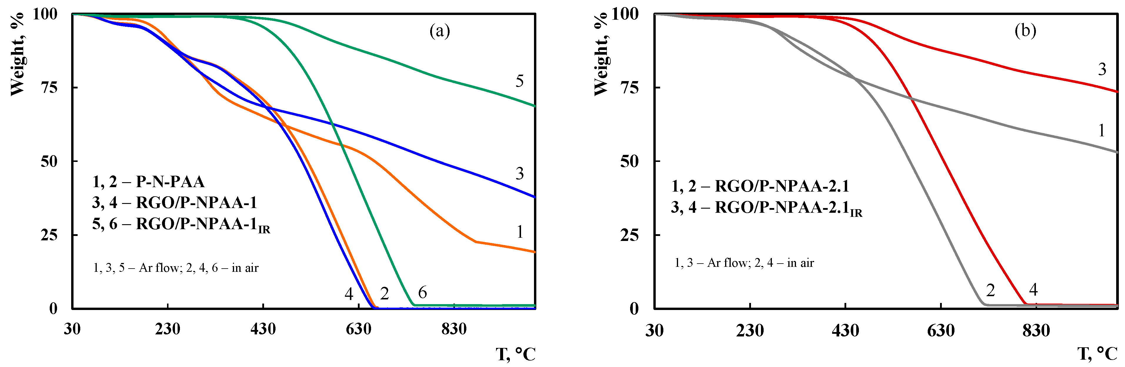
| Materials | Property | |||
|---|---|---|---|---|
| * T5%, °C | ** T50%, °C | Weight Loss at 350 °C, % | *** Residue, % | |
| PDPAC | 185/205 | 523/663 | 20/29 | 20 |
| RGO/P-N-PAA-1 | 183/180 | 511/794 | 19/26 | 38 |
| RGO/P-N-PAA-1IR | 436/515 | 609/>1000 | 1/1 | 69 |
| RGO/P-N-PAA-2.1 | 279/276 | 565/>1000 | 11/14 | 53 |
| RGO/P-N-PAA-2.1IR | 453/505 | 636/>1000 | 1/1 | 74 |
| Materials | ID/IG | I2D/IG | σ, S/cm |
|---|---|---|---|
| P-N-PAA | 0.93 | 0.43 | 8.8 × 10⁻¹¹ |
| RGO/P-N-PAA-1 | 0.92 | 0.44 | 1.8 × 10⁻⁸ |
| RGO/P-N-PAA-1IR | 0.89 | 0.56 | 2.3 × 10⁻¹ |
| RGO/P-N-PAA-2.1 | 0.95 | 0.48 | 6.7 × 10⁻³ |
| RGO/P-N-PAA-2.2 | 0.91 | 0.50 | 2.7 × 10⁻¹ |
| RGO/P-N-PAA-2.1IR | 0.85 | 0.51 | 2.6 × 10⁻¹ |
| RGO/P-N-PAA-2.2IR | 0.82 | 0.57 | 1.1 |
| Hybrid Electrodes | C1s, at% | O1s, at% | N1s, at% | S2p, at% |
|---|---|---|---|---|
| GF/P-N-PAA | 81.79 | 12.19 | 4.97 | 1.05 |
| AGF/RGO/P-N-PAA-1 | 79.02 | 13.14 | 5.12 | 2.72 |
| AGF/RGO/P-N-PAA-1IR | 85.23 | 8.35 | 4.12 | 1.42 |
| AGF/RGO/P-N-PAA-2.1 | 73.53 | 15.69 | 6.40 | 4.39 |
| AGF/RGO/P-N-PAA-2.1IR | 79.73 | 11.64 | 4.14 | 4.49 |
| AGF/RGO/P-N-PAA-2.2IR | 86.52 | 7.59 | 4.24 | 1.44 |
| Hybrid Electrodes | Coatings Weight, mg | Discharge Current Density Icharge–discharge, mA∙cm−2 | Coating Specific Weight Capacitance Cw, F∙g−1 |
|---|---|---|---|
| GC/RGO/P-N-PAA-1 | 0.45 | 0.1 0.5 | 32.0 24.0 |
| GC/RGO/P-N-PAA-1IR | 0.30 | 0.1 0.5 | 12.0 10.2 |
| GC/RGO/P-N-PAA-2.1 | 0.32 | 0.1 0.5 | 17.5 9.5 |
| GC/RGO/P-N-PAA-2.1IR | 0.30 | 0.1 0.5 | 29.8 22.2 |
| Hybrid Electrodes | Coatings Weight, mg | Discharge Current Density Icharge–discharge, mA∙cm−2 | Electrode Specific Surface Capacitance Cs, F∙cm−2 | Coating Specific Weight Capacitance Cw, F∙g−1 |
|---|---|---|---|---|
| AGF/P-N-PAA | 0.49 | 0.5 1.5 3.0 | 0.196 0.098 0.031 | 202 106 63 |
| AGF/RGO/P-N-PAA-1 | 0.37 | 0.5 1.5 3.0 | 0.196 0.114 0.070 | 268 184 111 |
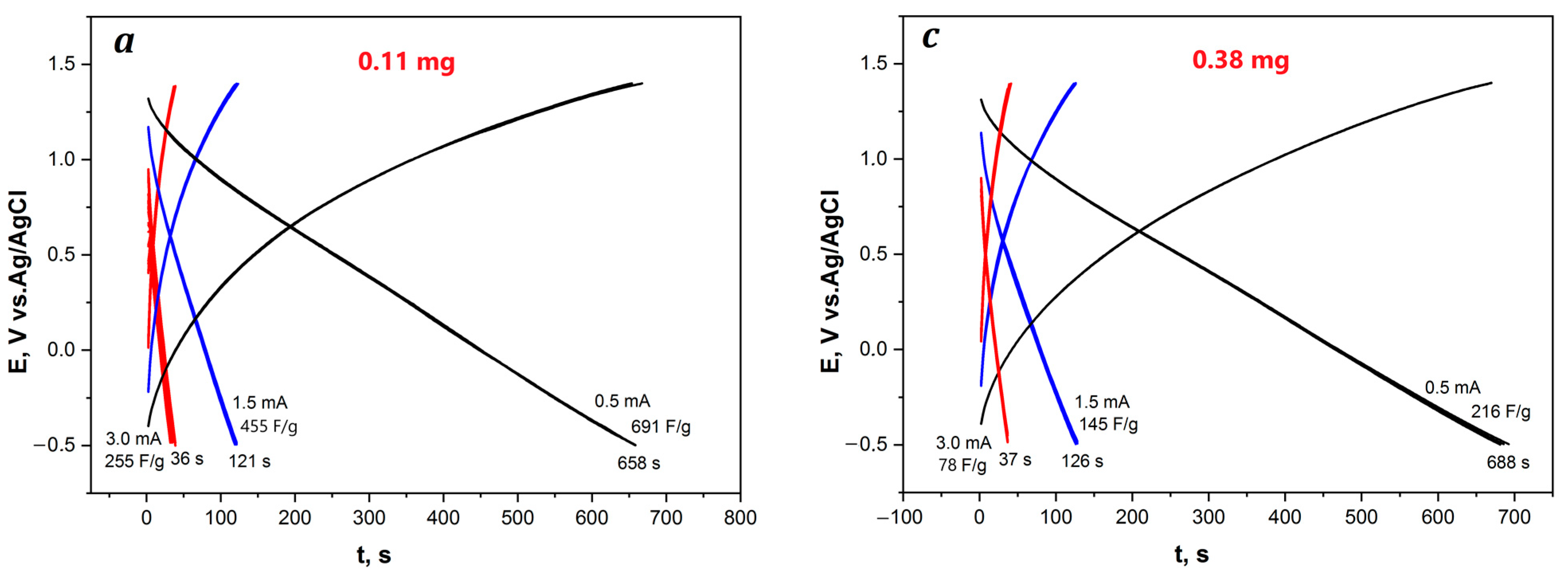
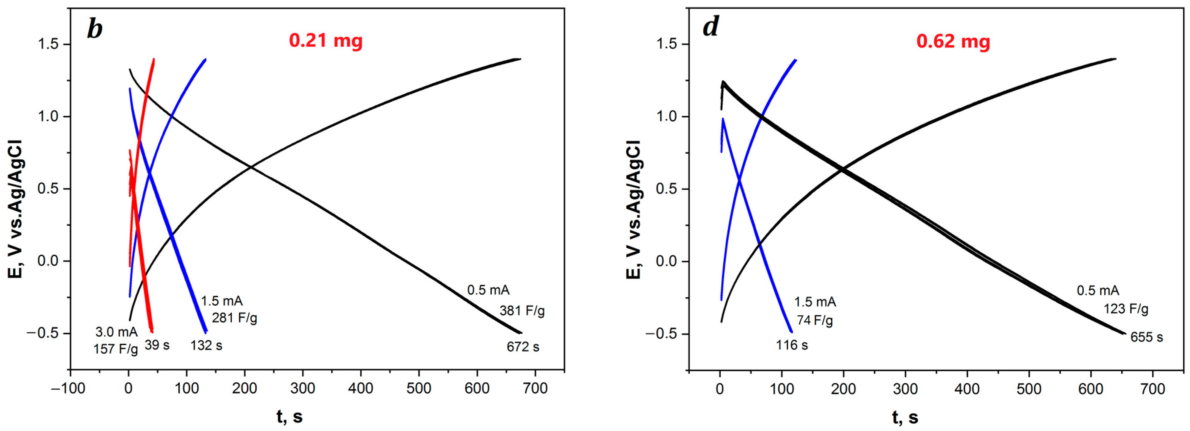
| AGF/RGO/P-N-PAA-1IR | 0.11 | 0.5 1.5 3.0 | 0.173 0.096 0.057 | 691 455 255 |
| 0.21 | 0.5 1.5 3.0 | 0.177 0.105 0.062 | 381 281 157 | |
| 0.38 | 0.5 1.5 3.0 | 0.182 0.101 0.058 | 216 145 78 | |
| 0.62 | 0.5 1.5 | 0.173 0.092 | 123 74 | |
| AGF/RGO/P-N-PAA-2.1 | 0.21 | 0.5 1.5 3.0 | 0.255 0.156 0.098 | 752 524 329 |
| 0.29 | 0.5 1.5 3.0 | 0.215 0.139 0.095 | 407 321 255 | |
| AGF/RGO/P-N-PAA-2.1IR | 0.35 | 0.5 1.5 3.0 | 0.229 0.148 0.099 | 377 291 200 |
| AGF/RGO/P-N-PAA-2.2IR | 0.33 | 0.5 1.5 3.0 | 0.200 0.118 0.076 | 324 218 142 |
Disclaimer/Publisher’s Note: The statements, opinions and data contained in all publications are solely those of the individual author(s) and contributor(s) and not of MDPI and/or the editor(s). MDPI and/or the editor(s) disclaim responsibility for any injury to people or property resulting from any ideas, methods, instructions or products referred to in the content. |
© 2023 by the authors. Licensee MDPI, Basel, Switzerland. This article is an open access article distributed under the terms and conditions of the Creative Commons Attribution (CC BY) license (https://creativecommons.org/licenses/by/4.0/).
Share and Cite
Ozkan, S.Z.; Tkachenko, L.I.; Efimov, O.N.; Karpacheva, G.P.; Nikolaeva, G.V.; Kostev, A.I.; Dremova, N.N.; Kabachkov, E.N. Advanced Electrode Coatings Based on Poly-N-Phenylanthranilic Acid Composites with Reduced Graphene Oxide for Supercapacitors. Polymers 2023, 15, 1896. https://doi.org/10.3390/polym15081896
Ozkan SZ, Tkachenko LI, Efimov ON, Karpacheva GP, Nikolaeva GV, Kostev AI, Dremova NN, Kabachkov EN. Advanced Electrode Coatings Based on Poly-N-Phenylanthranilic Acid Composites with Reduced Graphene Oxide for Supercapacitors. Polymers. 2023; 15(8):1896. https://doi.org/10.3390/polym15081896
Chicago/Turabian StyleOzkan, Sveta Zhiraslanovna, Lyudmila Ivanovna Tkachenko, Oleg Nikolaevich Efimov, Galina Petrovna Karpacheva, Galina Vasilevna Nikolaeva, Aleksandr Ivanovich Kostev, Nadejda Nikolaevna Dremova, and Evgeny Nikolaevich Kabachkov. 2023. "Advanced Electrode Coatings Based on Poly-N-Phenylanthranilic Acid Composites with Reduced Graphene Oxide for Supercapacitors" Polymers 15, no. 8: 1896. https://doi.org/10.3390/polym15081896
APA StyleOzkan, S. Z., Tkachenko, L. I., Efimov, O. N., Karpacheva, G. P., Nikolaeva, G. V., Kostev, A. I., Dremova, N. N., & Kabachkov, E. N. (2023). Advanced Electrode Coatings Based on Poly-N-Phenylanthranilic Acid Composites with Reduced Graphene Oxide for Supercapacitors. Polymers, 15(8), 1896. https://doi.org/10.3390/polym15081896