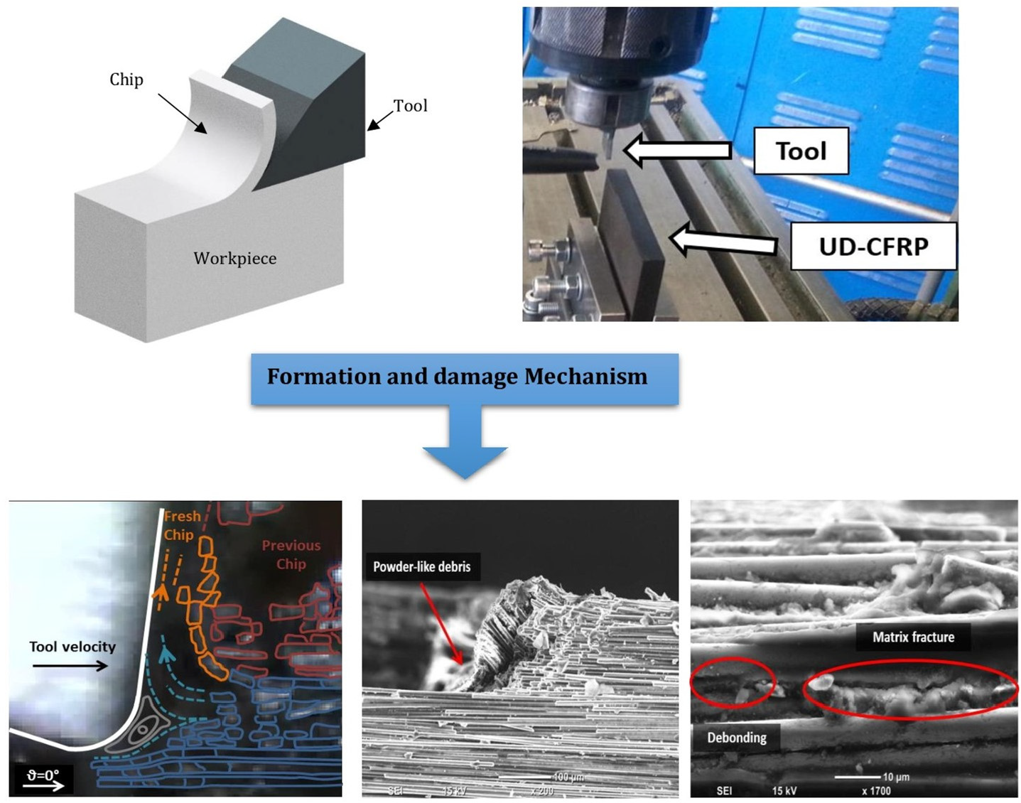
Figure 1.
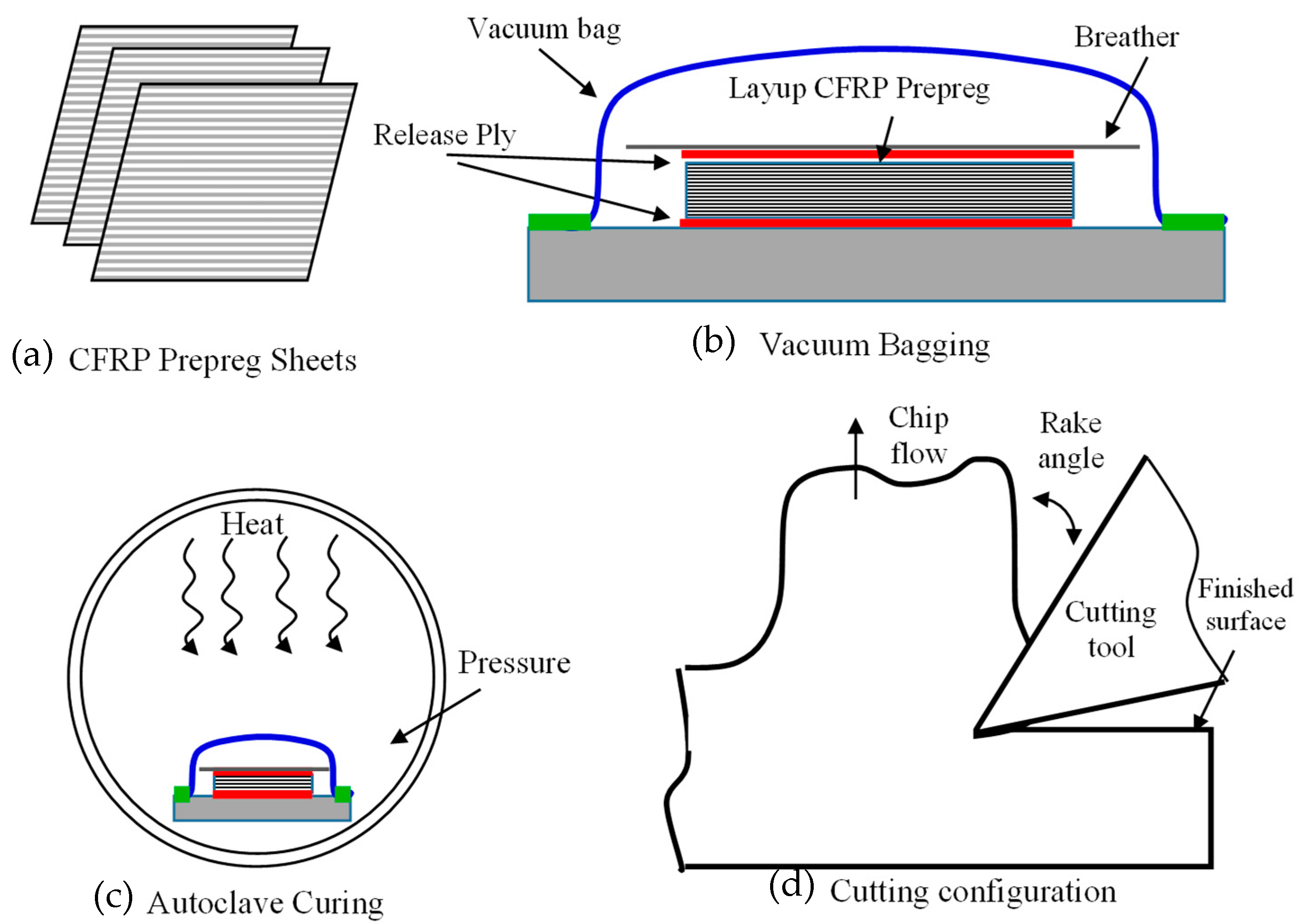
A schematic of the composite preparation and the cutting process (a) CFRP Prepeg sheets, (b) Vacuum Bagging, (c) Autoclave Curing, (d) Cutting Configuration.
Figure 1.
A schematic of the composite preparation and the cutting process (a) CFRP Prepeg sheets, (b) Vacuum Bagging, (c) Autoclave Curing, (d) Cutting Configuration.
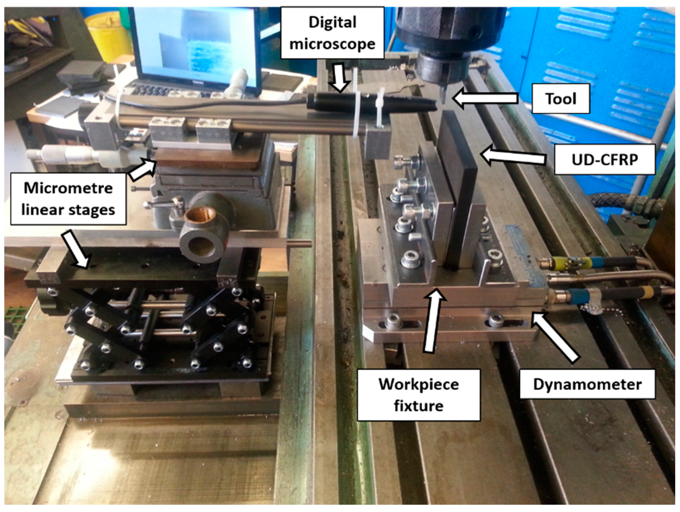
Figure 2.
Experimental setup for unidirectional orthogonal cutting.
Figure 2.
Experimental setup for unidirectional orthogonal cutting.
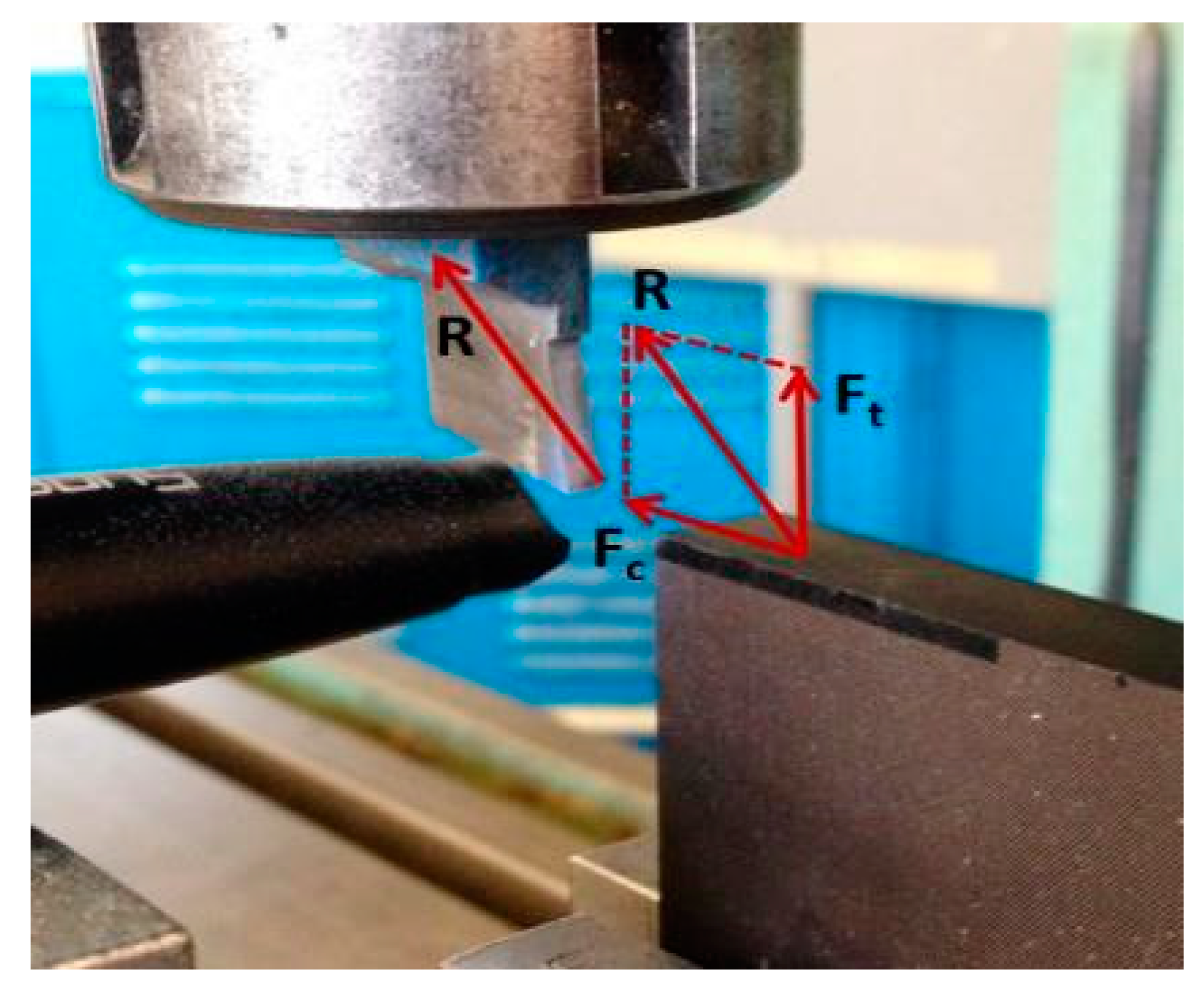
Figure 3.
The analysis of resultant machining force.
Figure 3.
The analysis of resultant machining force.
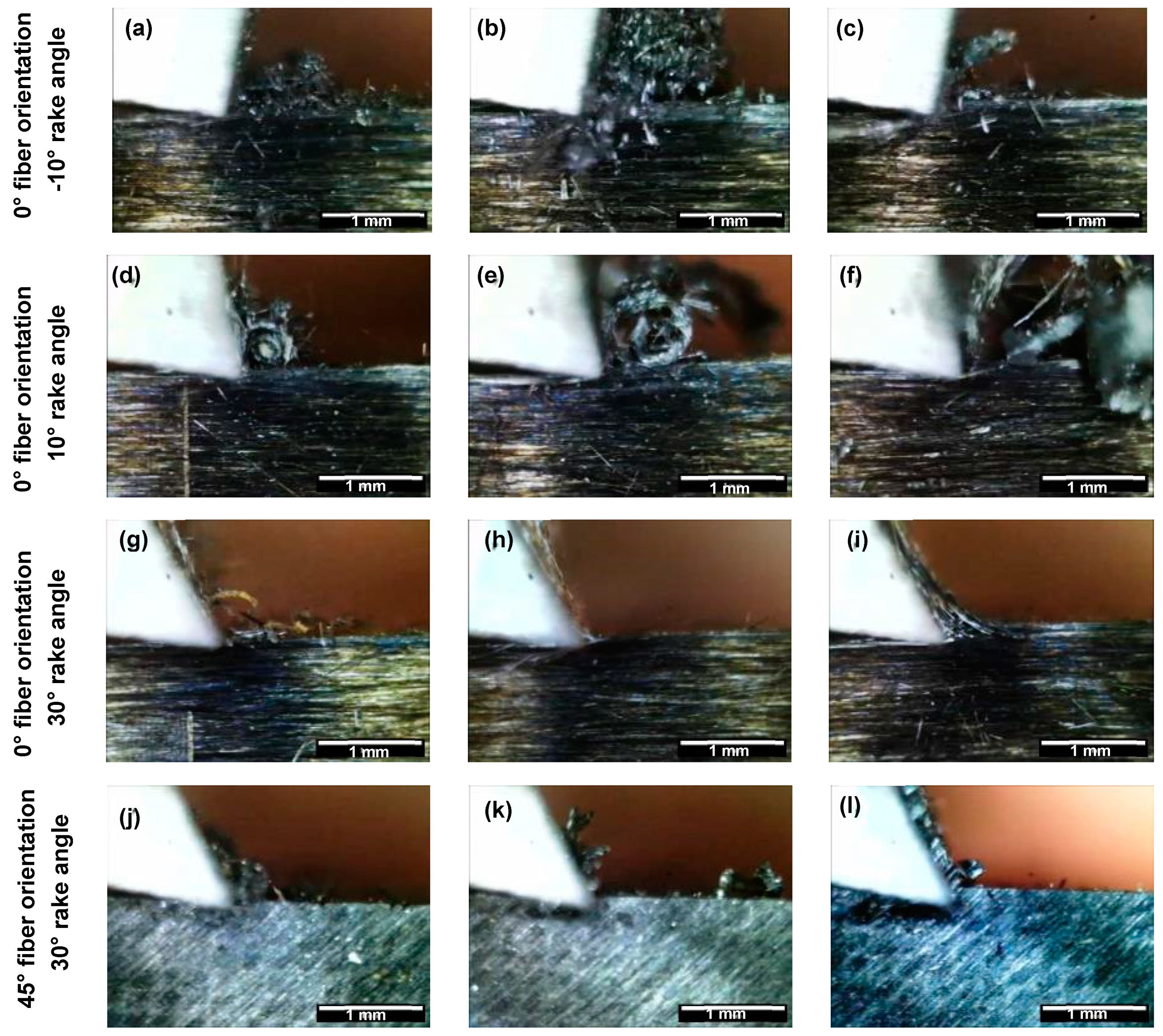
Figure 4.
Chip formation at a depth of cut of (a,d,g,j) 50 µm, (b,e,h,k) 100 µm and (c,f,i,l) 150 µm. (The white scale bar = 1mm).
Figure 4.
Chip formation at a depth of cut of (a,d,g,j) 50 µm, (b,e,h,k) 100 µm and (c,f,i,l) 150 µm. (The white scale bar = 1mm).
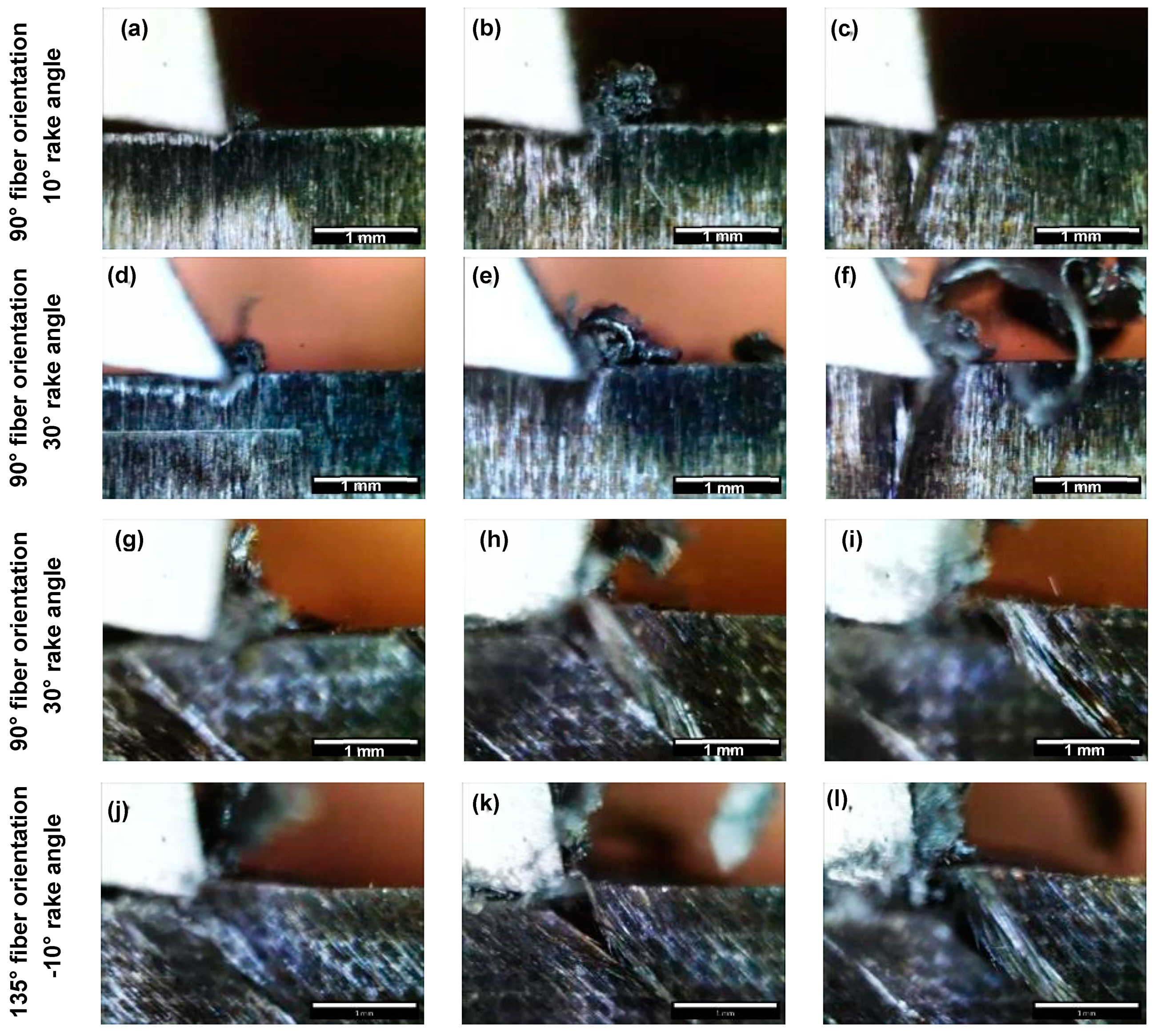
Figure 5.
Chip formation at a depth of cut of (a,d,g,j) 50 µm, (b,e,h,k) 100 µm and (c,f,i,l) 150 µm. (The white scale bar = 1mm).
Figure 5.
Chip formation at a depth of cut of (a,d,g,j) 50 µm, (b,e,h,k) 100 µm and (c,f,i,l) 150 µm. (The white scale bar = 1mm).
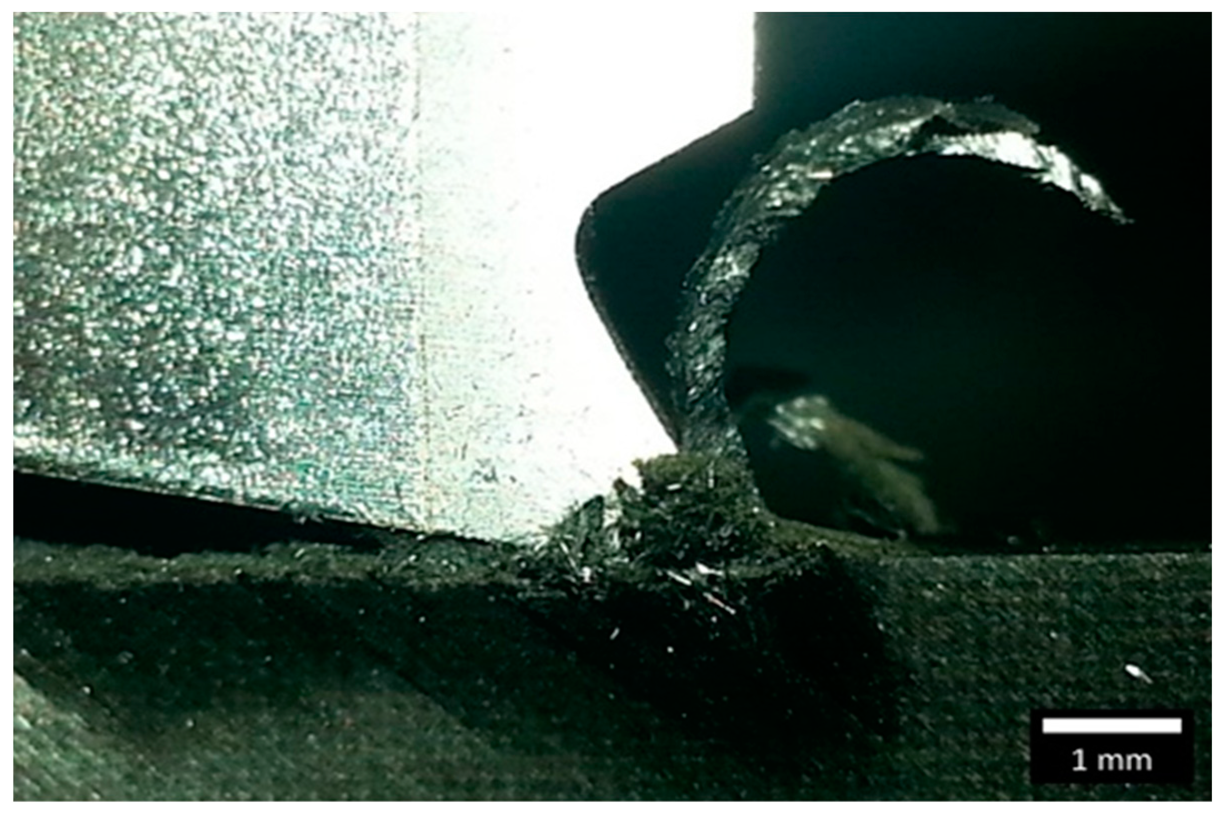
Figure 6.
Chip formation for experiment 34 at fibre orientation of 135°, rake angle of 30°, and depth of cut of 150 µm. (The white scale bar = 1 mm).
Figure 6.
Chip formation for experiment 34 at fibre orientation of 135°, rake angle of 30°, and depth of cut of 150 µm. (The white scale bar = 1 mm).
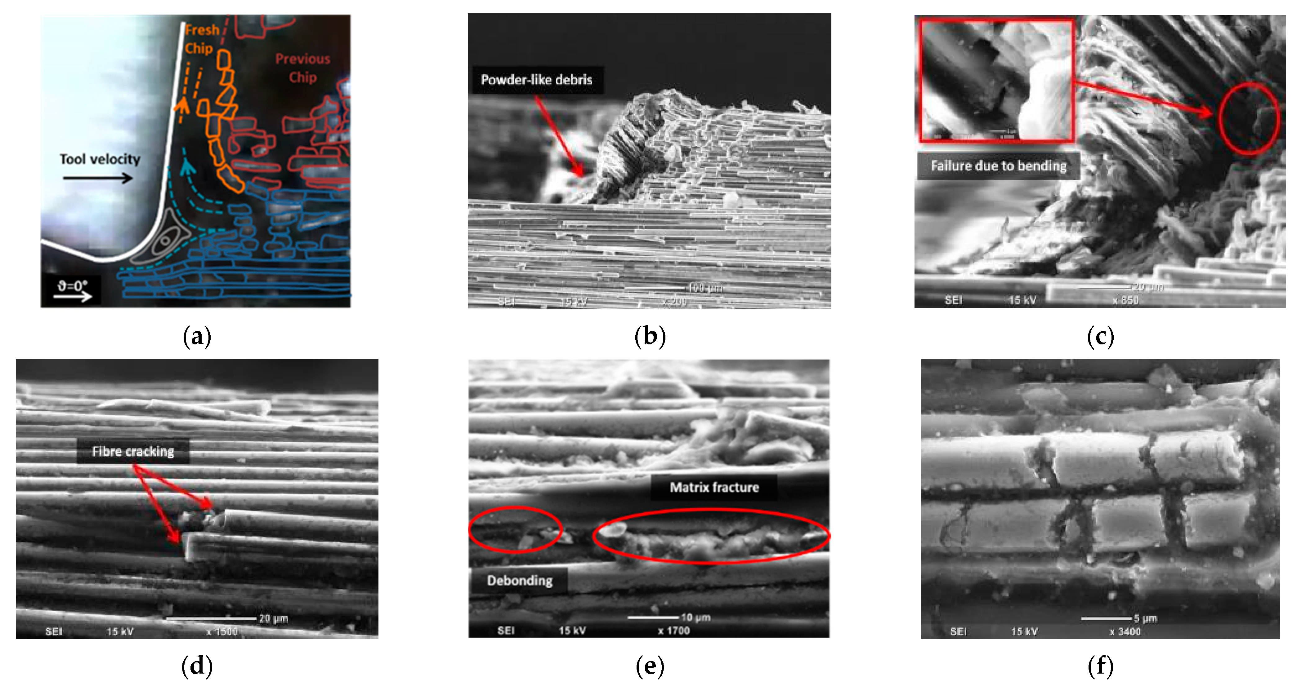
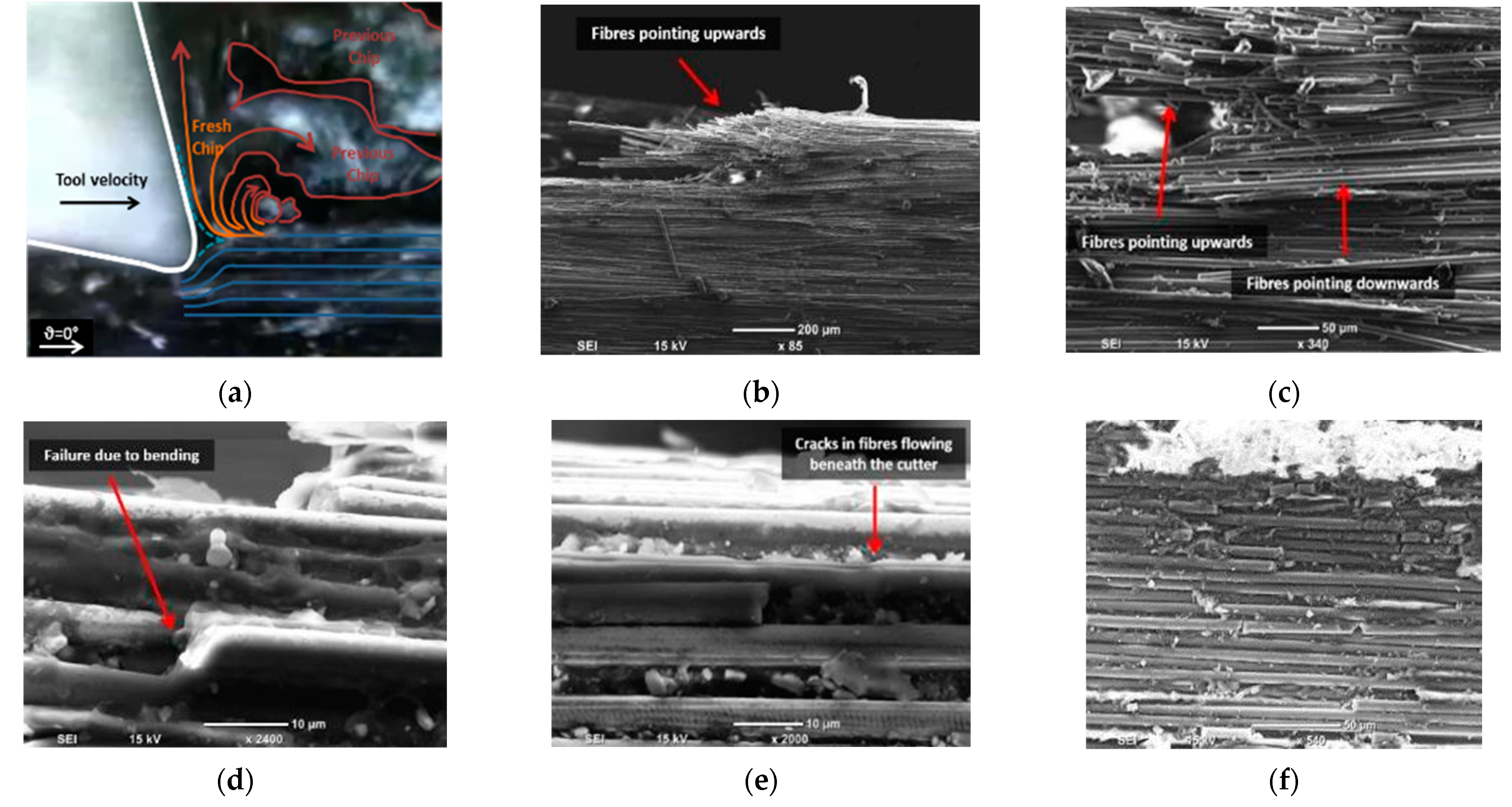
Figure 7.
Chip formation for samples with a fibre orientation of 0° and a rake angle of −10°: (a) a schematic diagram overlaid on a digital image, (b) the chip root, (c) a magnified SEM image of the chip root, (d) a side view showing fibre damage, (e) a side view SEM image showing matrix damage, and (f) a top view SEM image of the machined surface.
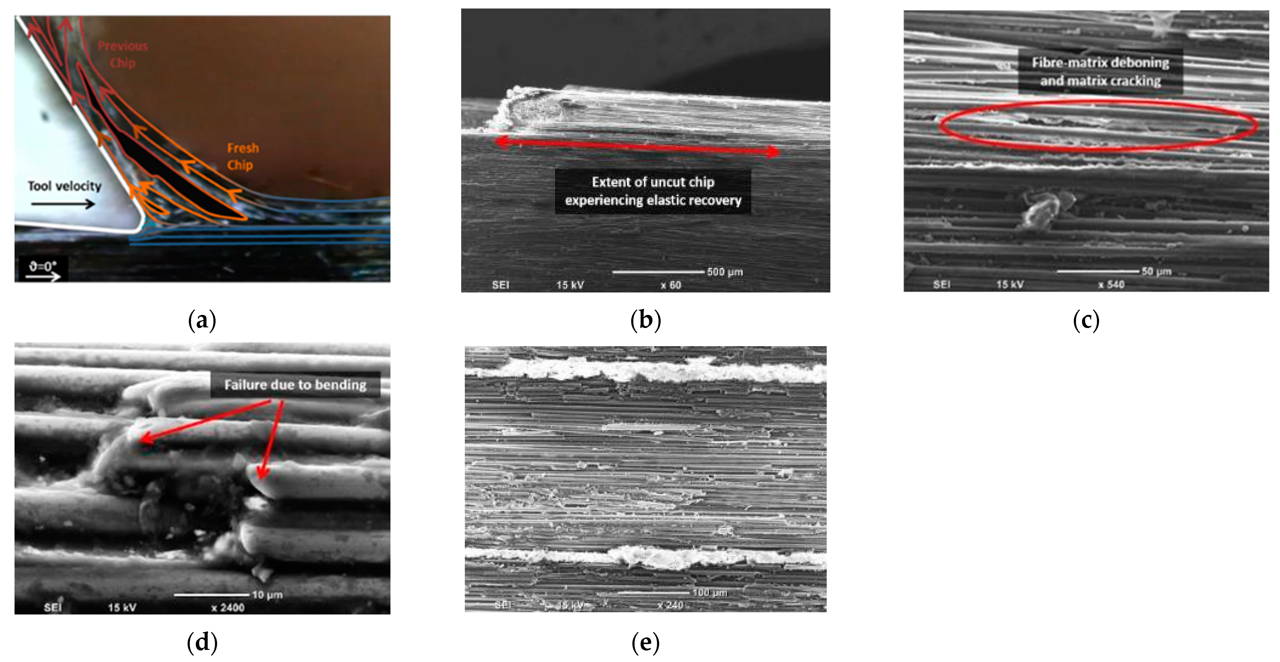
Figure 8.
Chip formation at fibre orientation 0° and tool rake angle 10°, (a) a schematic overlaid on a digital image; (b) The chip root; (c) a magnified view of the chip root; (d) a side view showing fibre failure; (e) a side view revealing fibre crack; and (f) a top view of the machined surface.
Figure 8.
Chip formation at fibre orientation 0° and tool rake angle 10°, (a) a schematic overlaid on a digital image; (b) The chip root; (c) a magnified view of the chip root; (d) a side view showing fibre failure; (e) a side view revealing fibre crack; and (f) a top view of the machined surface.
Figure 9.
Chip formation observed at fibre orientation 0° and tool rake angle 30°: (a) schematic overlaid on the digital image; (b) The chip root; (c) side view highlighting matrix damage; (d) side view showing fibre failure; (e) top view of the machined surface.
Figure 9.
Chip formation observed at fibre orientation 0° and tool rake angle 30°: (a) schematic overlaid on the digital image; (b) The chip root; (c) side view highlighting matrix damage; (d) side view showing fibre failure; (e) top view of the machined surface.
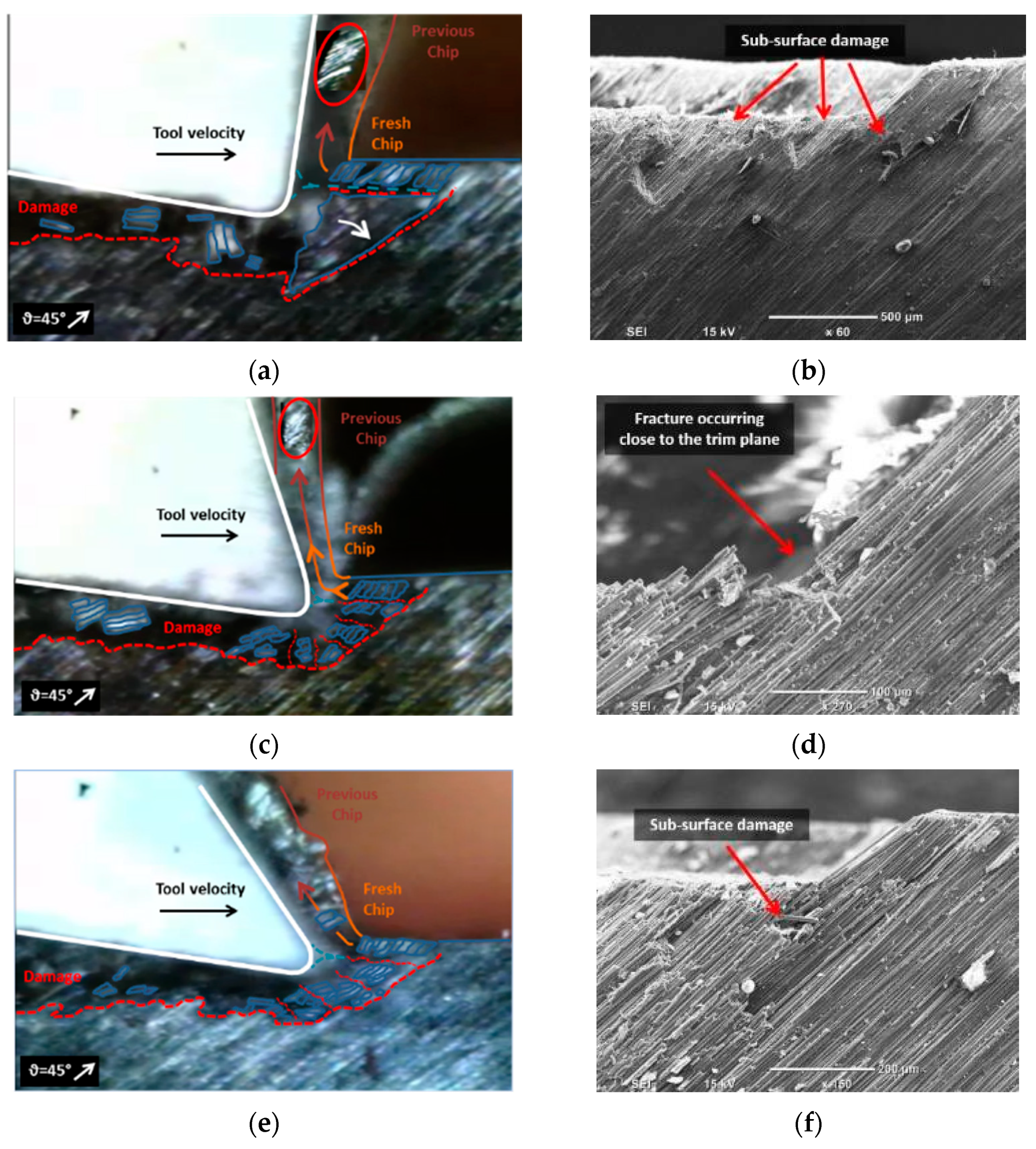
Figure 10.
Chip formation at fibre orientation 45° and tool rake angle (a,b) −10°; (c,d) 10°; (e,f) 30°.
Figure 10.
Chip formation at fibre orientation 45° and tool rake angle (a,b) −10°; (c,d) 10°; (e,f) 30°.
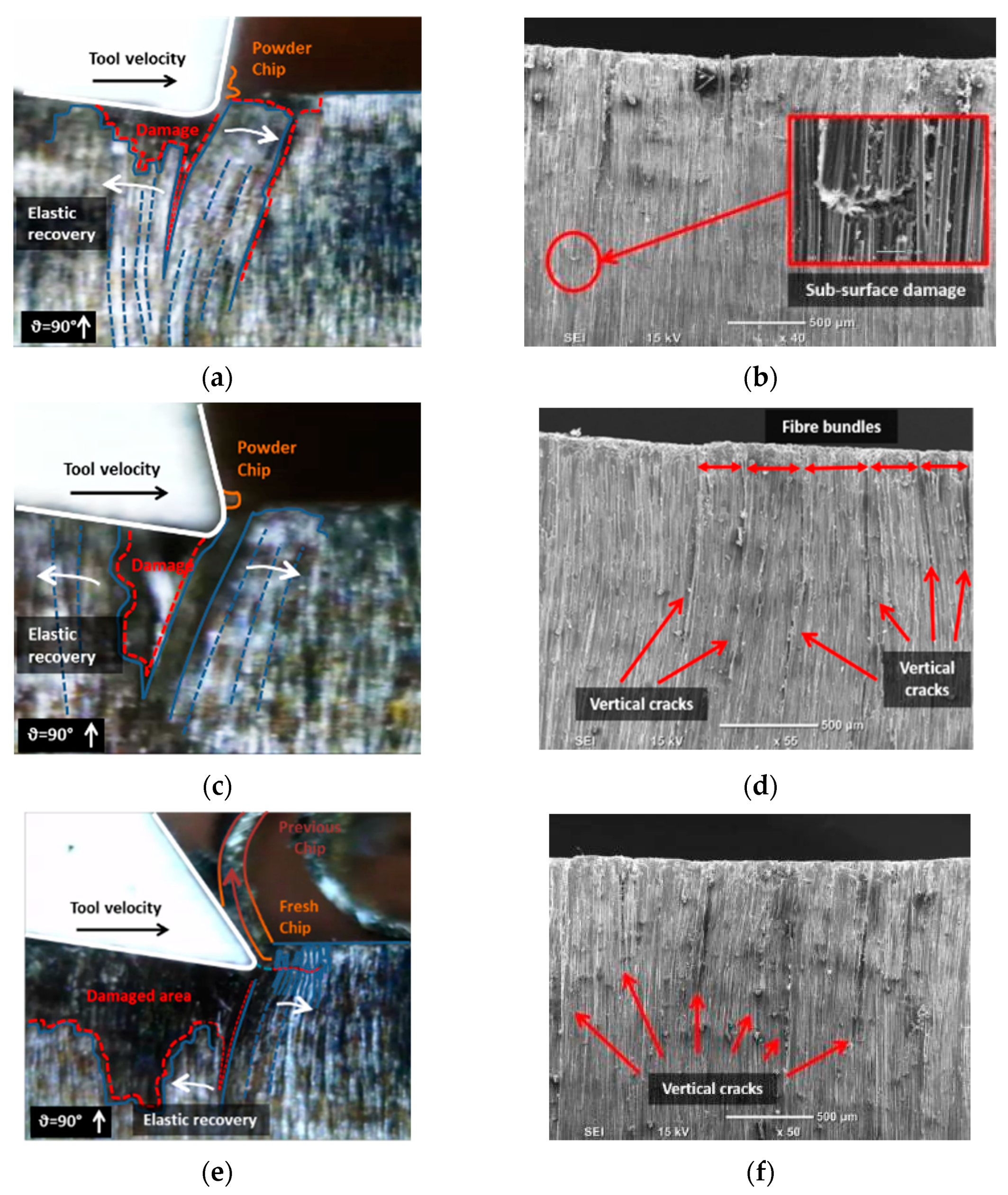
Figure 11.
Chip formation at fibre orientation 90° and tool rake angle (a,b) −10°; (c,d) 10°; (e,f) 30°.
Figure 11.
Chip formation at fibre orientation 90° and tool rake angle (a,b) −10°; (c,d) 10°; (e,f) 30°.
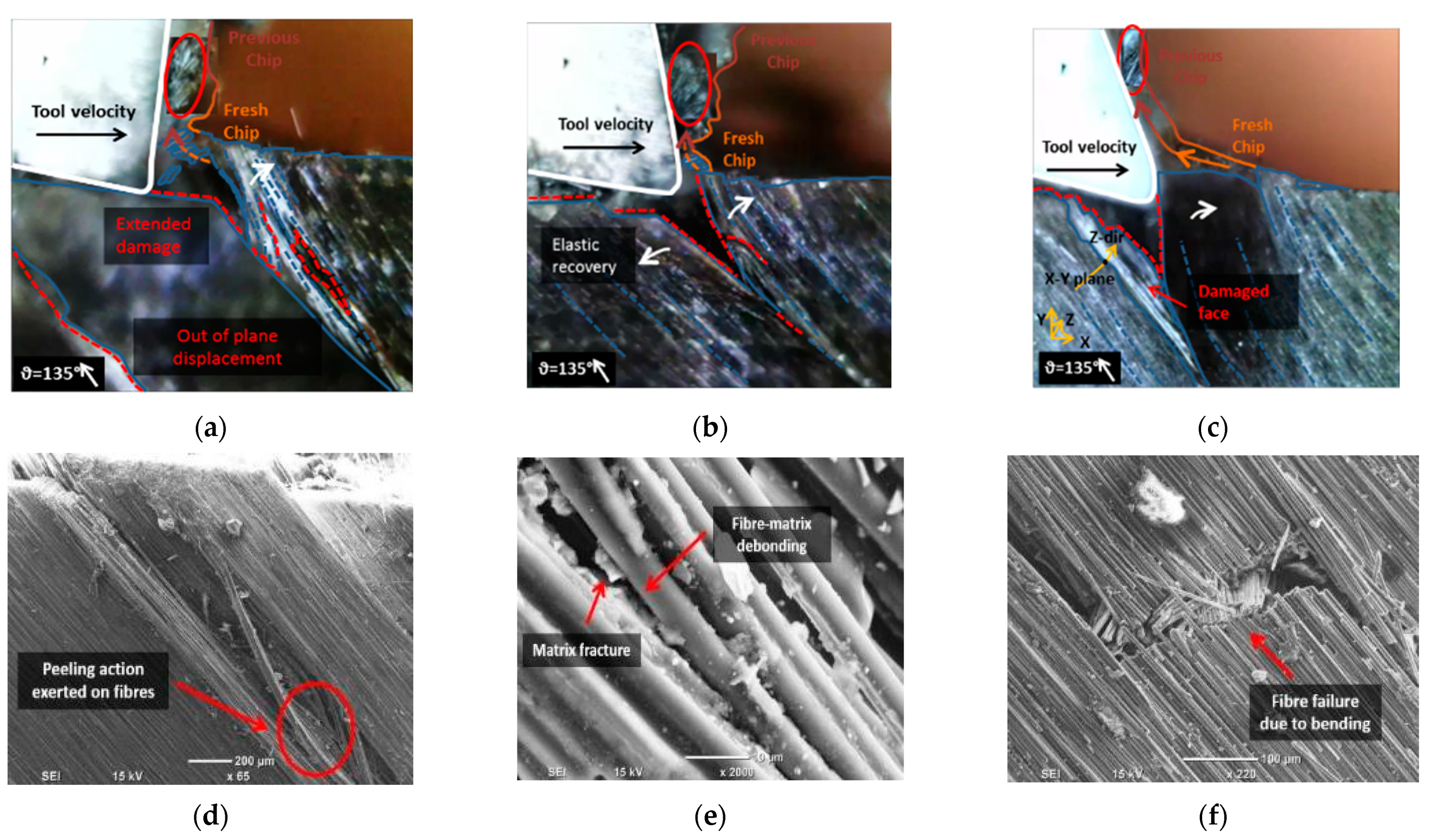
Figure 12.
Chip formation at fibre orientation 135° and tool rake angle of (a) −10°; (b) 10°; (c) 30°; and (d–f) workpiece damage on the side view.
Figure 12.
Chip formation at fibre orientation 135° and tool rake angle of (a) −10°; (b) 10°; (c) 30°; and (d–f) workpiece damage on the side view.
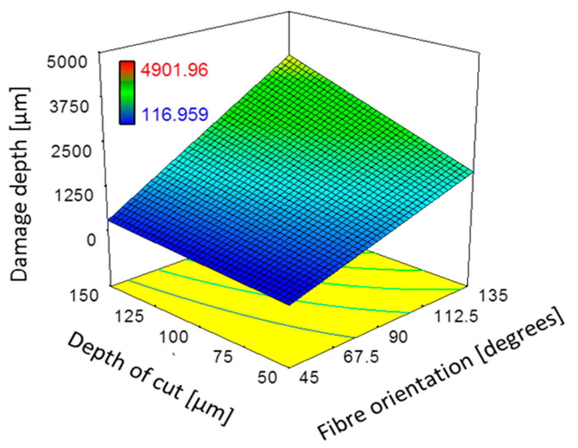
Figure 13.
The combined effect of depth of cut and fibre orientation and on damage depth for 10° and 570 mm/min.
Figure 13.
The combined effect of depth of cut and fibre orientation and on damage depth for 10° and 570 mm/min.
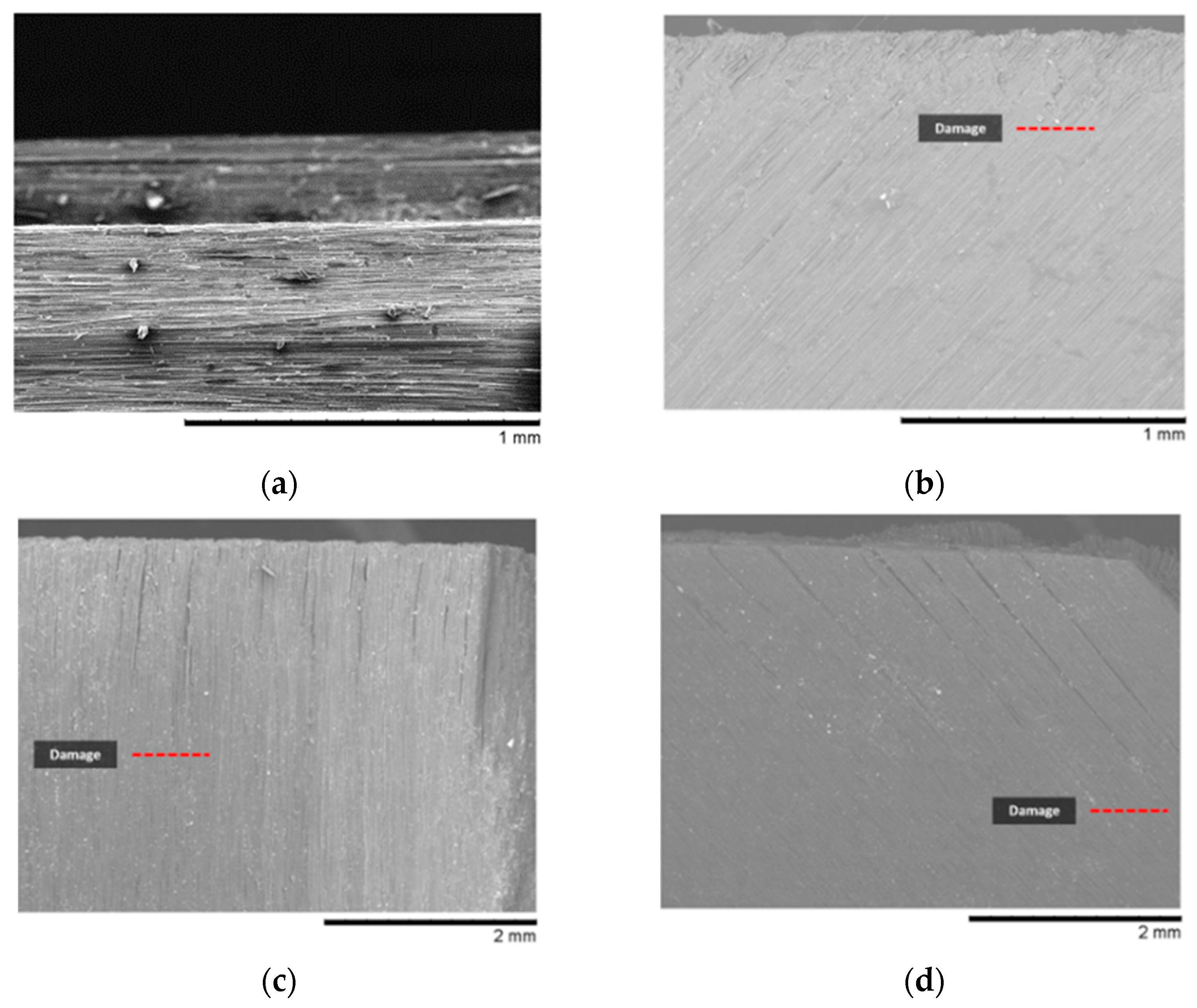
Figure 14.
Damage in machined workpiece for depth of cut 50 µm and fibre orientation (
a)
θ = 0°, (
b)
θ = 45°, (
c)
θ = 90°, and (
d)
θ = 135°, which correspond to experiments 5, 14, 23, and 32 in
Table 3, respectively.
Figure 14.
Damage in machined workpiece for depth of cut 50 µm and fibre orientation (
a)
θ = 0°, (
b)
θ = 45°, (
c)
θ = 90°, and (
d)
θ = 135°, which correspond to experiments 5, 14, 23, and 32 in
Table 3, respectively.
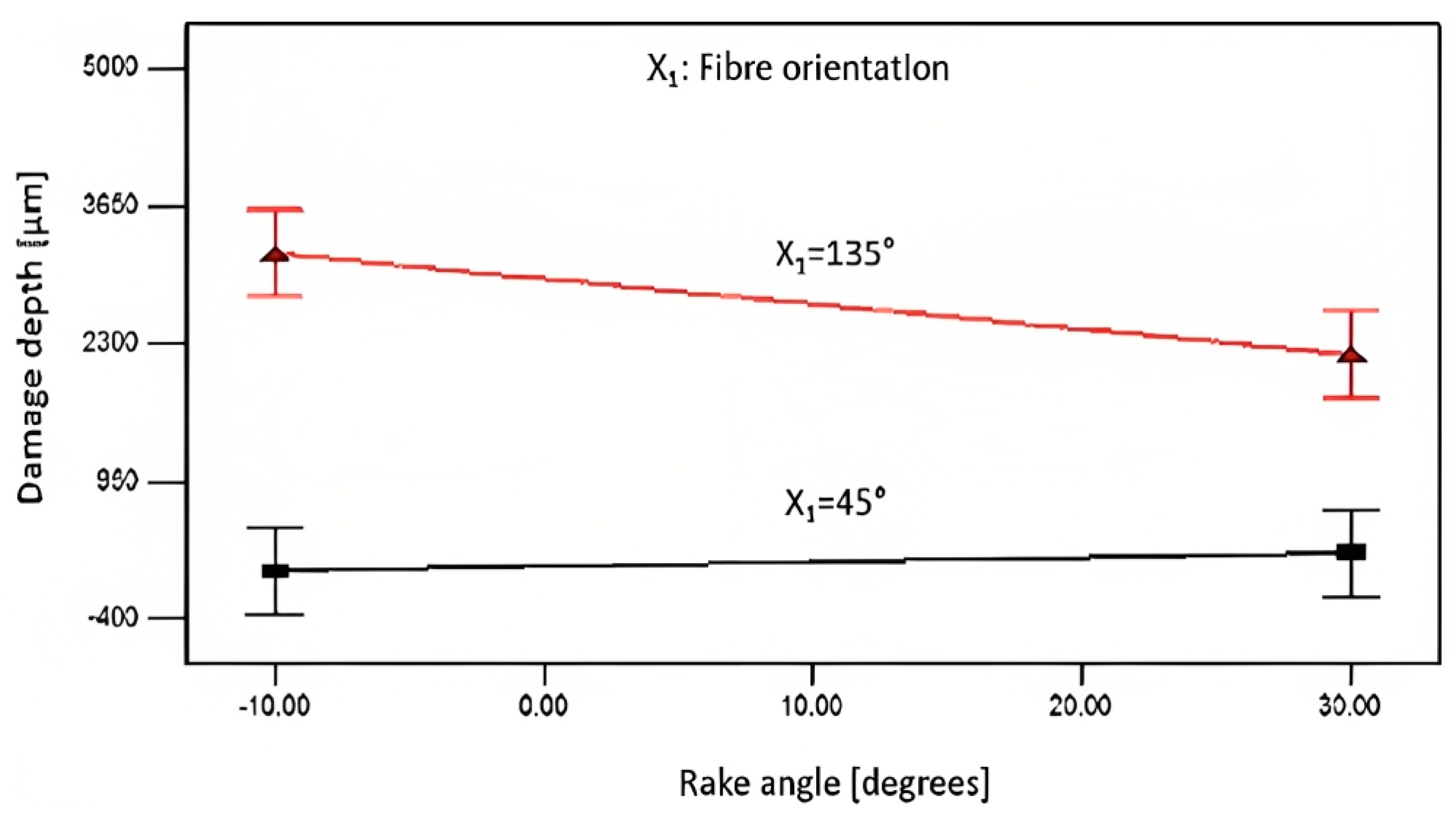
Figure 15.
Effect of fibre orientation and tool rake angle on the depth of cut of 100 µm and mm/min.
Figure 15.
Effect of fibre orientation and tool rake angle on the depth of cut of 100 µm and mm/min.
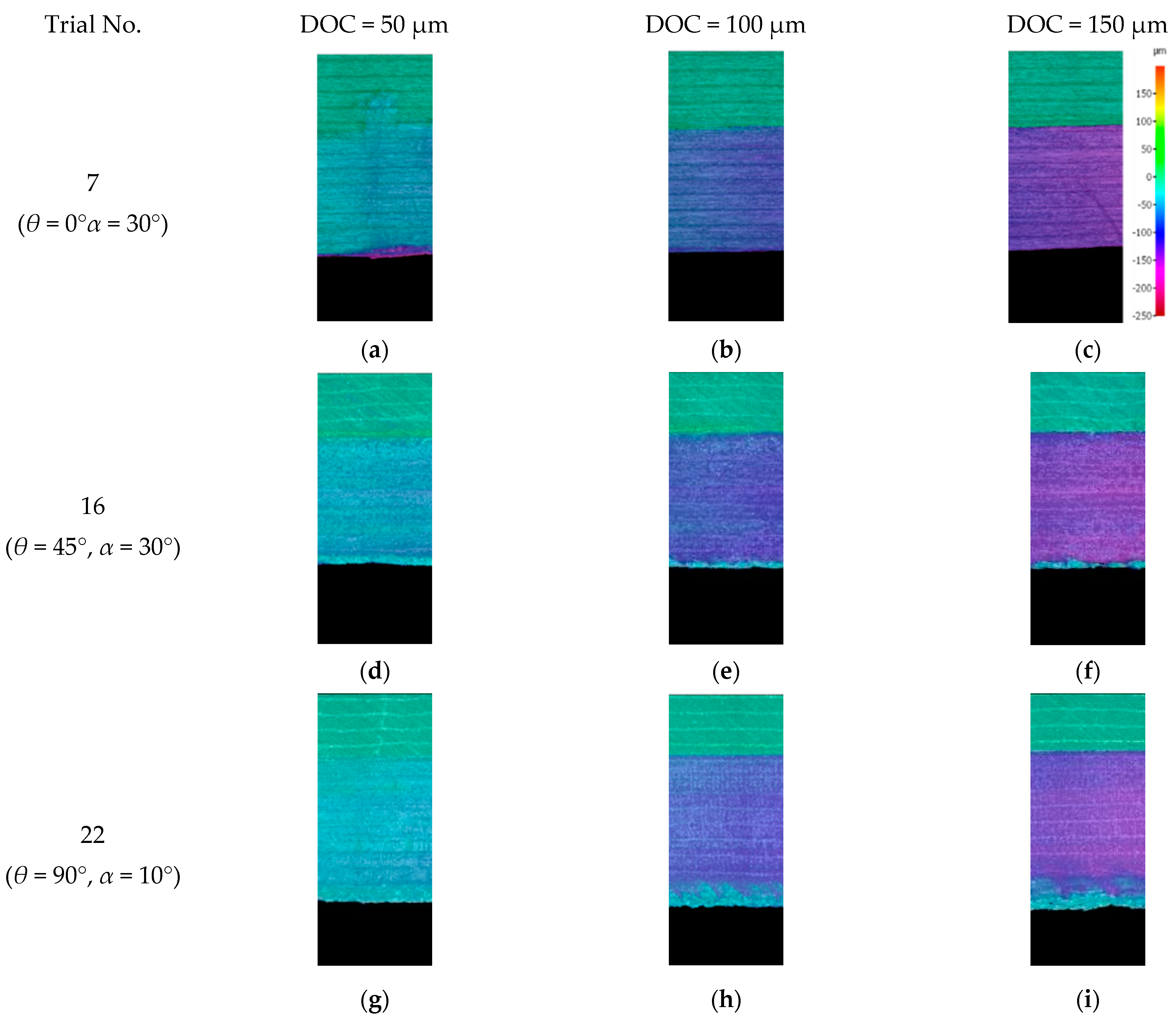
Figure 16.
The measured depth of cut from scanned surface profile for (a–c) Experiment 7 (orientation angle = 0° rake angle = 30°); (d–f) Experiment 16 (θ = 45°, α = 30°); and (g–i) Experiment 22 (orientation angle = 90°, rake angle = 10°).
Figure 16.
The measured depth of cut from scanned surface profile for (a–c) Experiment 7 (orientation angle = 0° rake angle = 30°); (d–f) Experiment 16 (θ = 45°, α = 30°); and (g–i) Experiment 22 (orientation angle = 90°, rake angle = 10°).
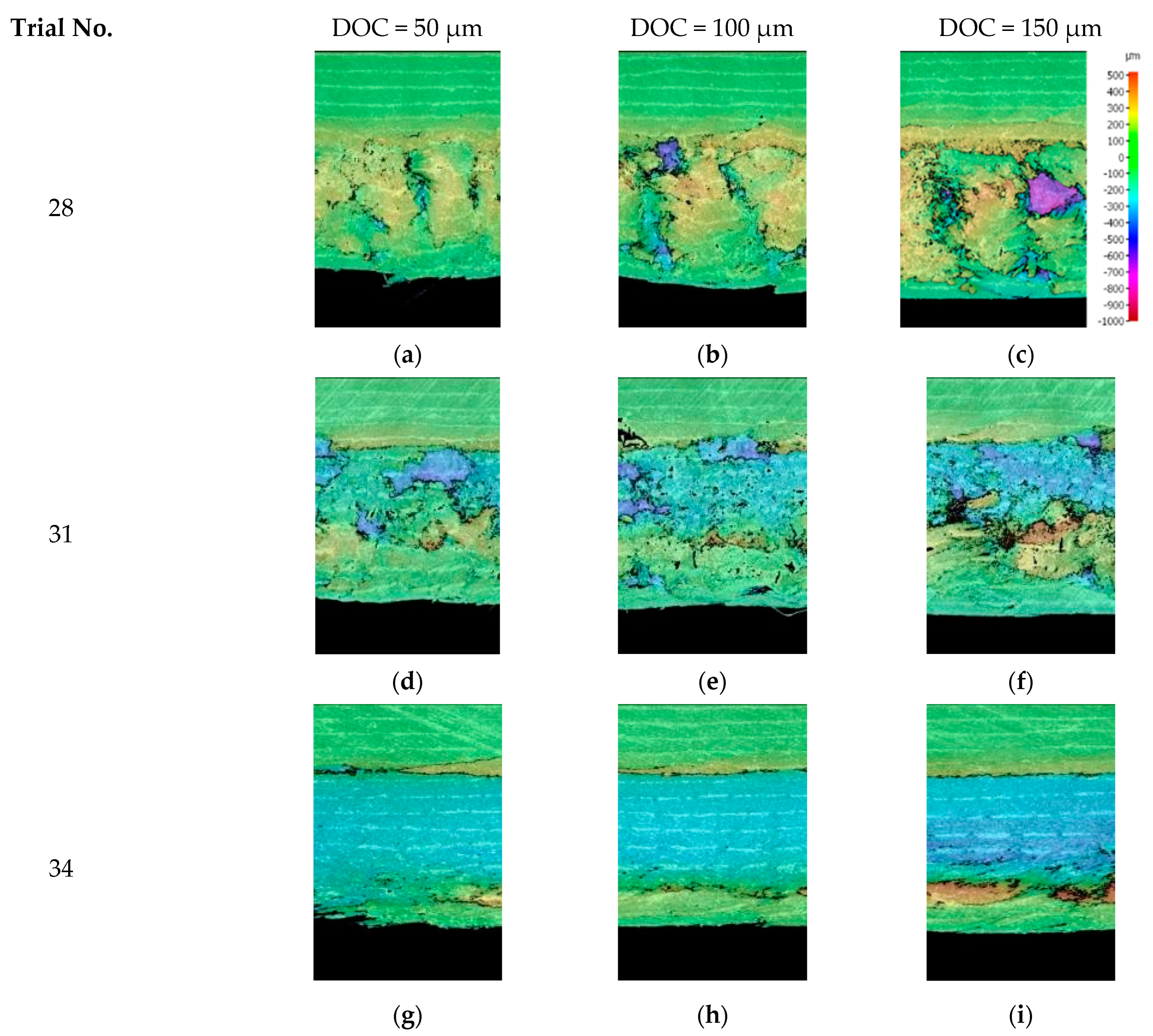
Figure 17.
The measured depth of cut from scanned surface profile for fibre orientation of 135° and cutting speed of 12 mm/m at different rake angles of (a–c) −10°; (d–f) 10°; and (g–i) 30°.
Figure 17.
The measured depth of cut from scanned surface profile for fibre orientation of 135° and cutting speed of 12 mm/m at different rake angles of (a–c) −10°; (d–f) 10°; and (g–i) 30°.
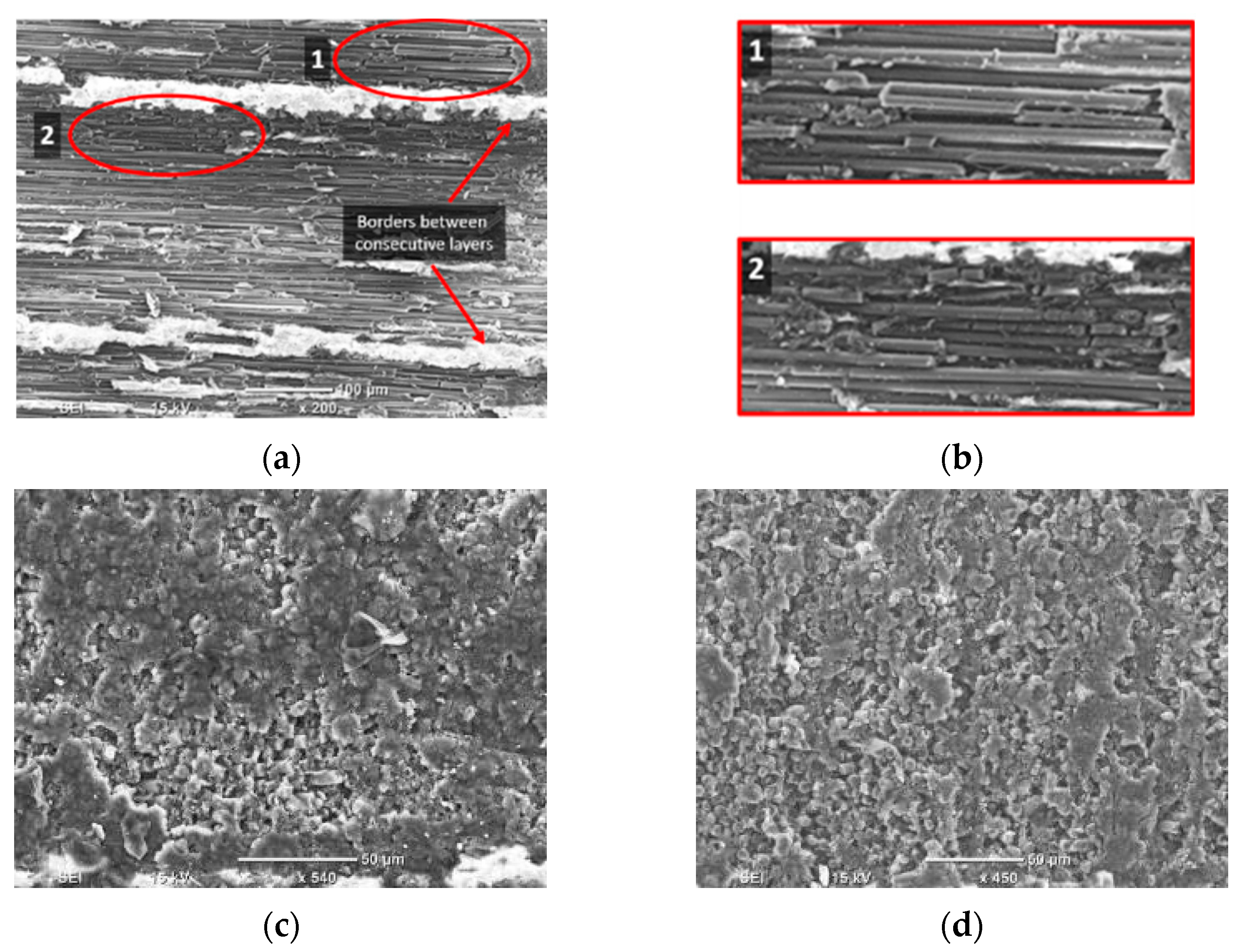
Figure 18.
SEM images of the machined surface for (a) Experiment 4 (θ = 0°); (b) magnification of Experiment 4; (c) Experiment 13 (θ = 45°); and (d) Experiment 22 (θ = 90°). The machining direction is from left to right.
Figure 18.
SEM images of the machined surface for (a) Experiment 4 (θ = 0°); (b) magnification of Experiment 4; (c) Experiment 13 (θ = 45°); and (d) Experiment 22 (θ = 90°). The machining direction is from left to right.
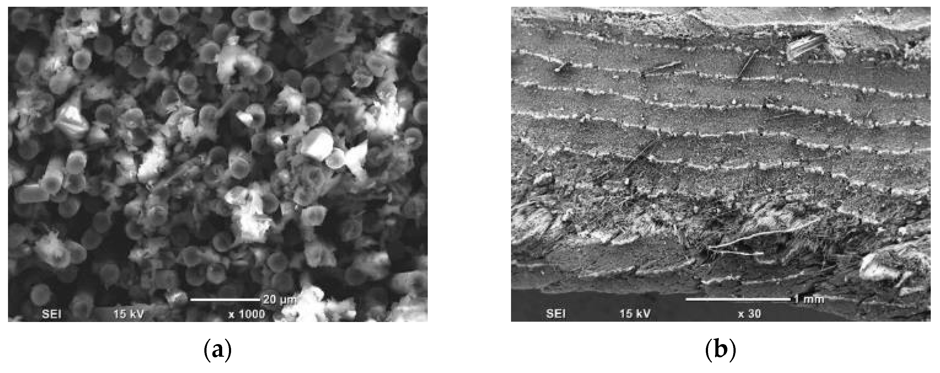
Figure 19.
SEM images of machined surfaces for (a) Experiment 31 (θ = 135°, α = 10°); and (b) Experiment 34 (θ = 135°, α = 30°), with machining direction from left to right.
Figure 19.
SEM images of machined surfaces for (a) Experiment 31 (θ = 135°, α = 10°); and (b) Experiment 34 (θ = 135°, α = 30°), with machining direction from left to right.
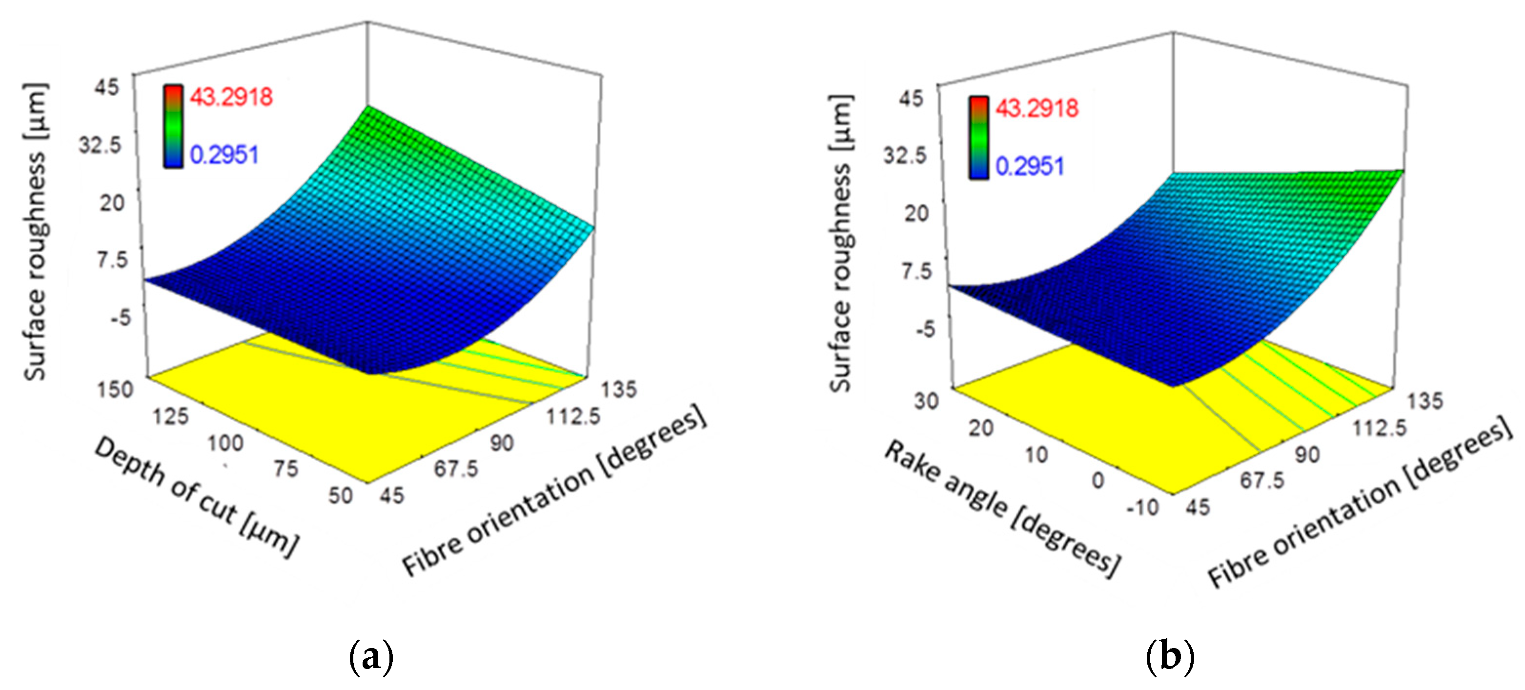
Figure 20.
The combined effect on surface roughness (Ra) of (a) depth of cut and fibre orientation at constant α: 10°; Vc: 57 mm/min; and (b) fibre orientation and tool rake angle at constant DOC: 100 µm; Vc: 570 mm/min.
Figure 20.
The combined effect on surface roughness (Ra) of (a) depth of cut and fibre orientation at constant α: 10°; Vc: 57 mm/min; and (b) fibre orientation and tool rake angle at constant DOC: 100 µm; Vc: 570 mm/min.
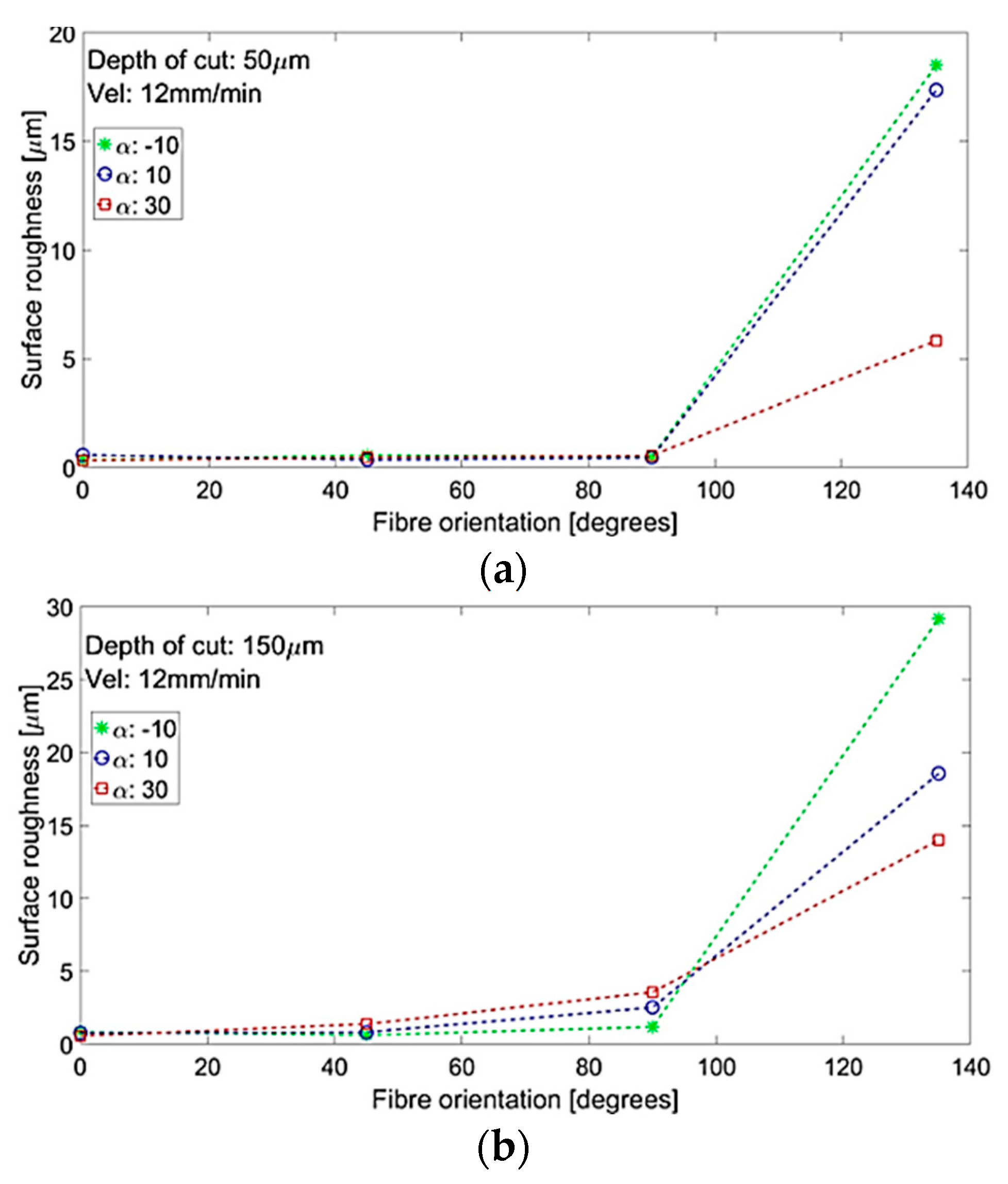
Figure 21.
Surface roughness and fibre orientation at various tool rake angles at depths of cut of (a) 50 µm and (b) 150 µm.
Figure 21.
Surface roughness and fibre orientation at various tool rake angles at depths of cut of (a) 50 µm and (b) 150 µm.
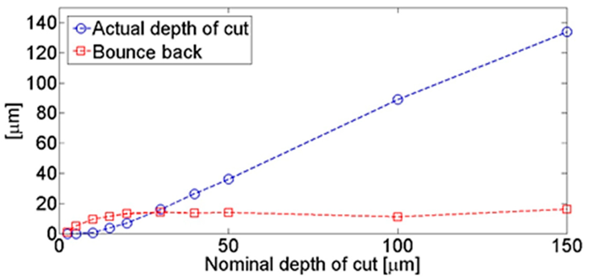
Figure 22.
Bounce back and actual cutting depth for a fibre orientation of 0°, a rake angle of −10°, and a cutting speed of 12 mm/min (Experiment 1).
Figure 22.
Bounce back and actual cutting depth for a fibre orientation of 0°, a rake angle of −10°, and a cutting speed of 12 mm/min (Experiment 1).
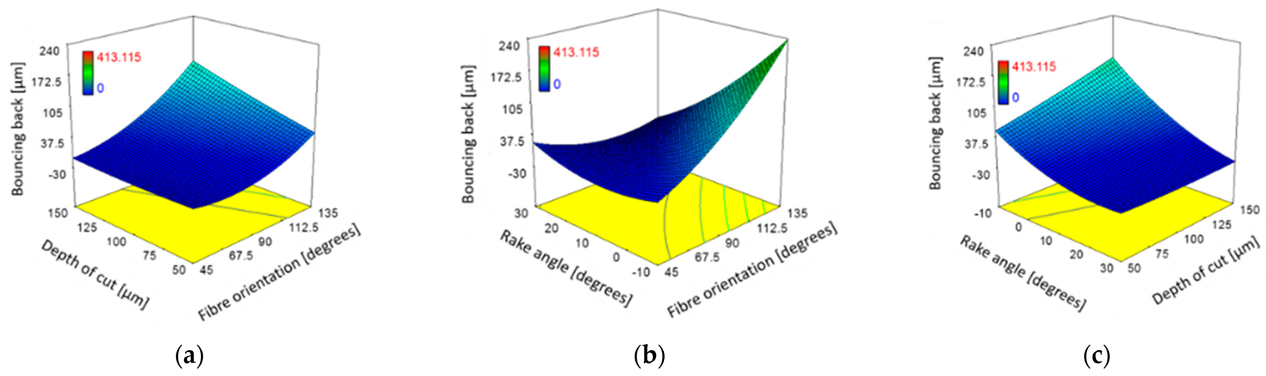
Figure 23.
The combined effect on bounce back for (a) fibre orientation and cutting depth at constant α: 10°; Vc: 570 mm/min; (b) fibre orientation and rake angle at constant DOC: 100 µm; Vc: 570 mm/min; (c) rake angle and cutting depth of constant θ: 90°; Vc: 570 mm/min.
Figure 23.
The combined effect on bounce back for (a) fibre orientation and cutting depth at constant α: 10°; Vc: 570 mm/min; (b) fibre orientation and rake angle at constant DOC: 100 µm; Vc: 570 mm/min; (c) rake angle and cutting depth of constant θ: 90°; Vc: 570 mm/min.
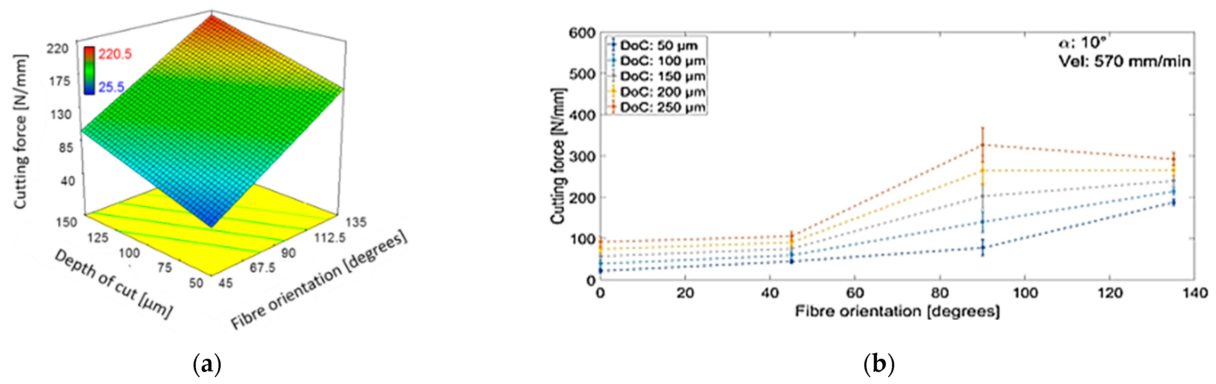
Figure 24.
(a) Effect of orientation of fibres and depth of cut on the cutting force, and (b) the measured cutting force versus fibre orientations at various cutting depths when machining at a rake angle of 10° and cutting speed of 570 mm/min.
Figure 24.
(a) Effect of orientation of fibres and depth of cut on the cutting force, and (b) the measured cutting force versus fibre orientations at various cutting depths when machining at a rake angle of 10° and cutting speed of 570 mm/min.
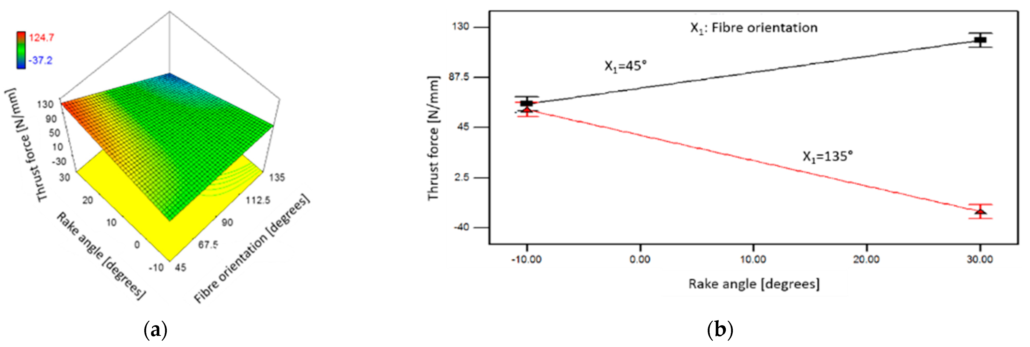
Figure 25.
The combined effect of orientation of fibres and tool rake angle on the thrust force when machining at DOC: 100 µm (a) 3D view, and (b) fibre orientations of 45° and 135°.
Figure 25.
The combined effect of orientation of fibres and tool rake angle on the thrust force when machining at DOC: 100 µm (a) 3D view, and (b) fibre orientations of 45° and 135°.
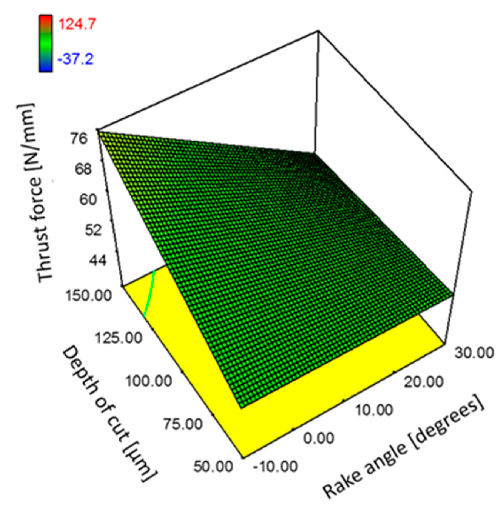
Figure 26.
The combined effect of depth of cut and tool rake angle on the thrust force for samples with fibre orientation 90°.
Figure 26.
The combined effect of depth of cut and tool rake angle on the thrust force for samples with fibre orientation 90°.
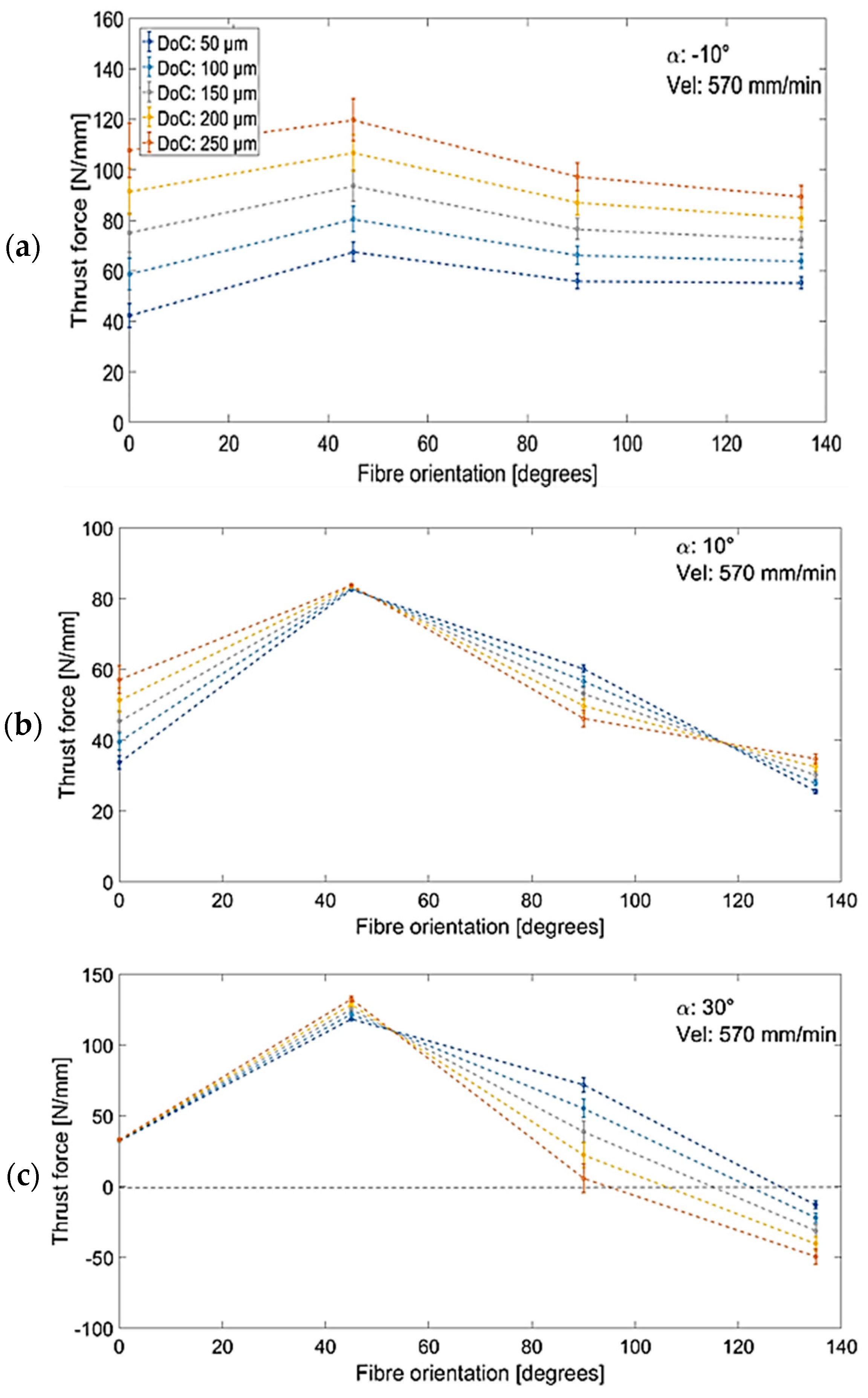
Figure 27.
The trend of thrust force with respect to fibre orientation during cutting at a speed of 570 mm/min and rake angles of (a) −10°, (b) 10°, (c) 30°.
Figure 27.
The trend of thrust force with respect to fibre orientation during cutting at a speed of 570 mm/min and rake angles of (a) −10°, (b) 10°, (c) 30°.
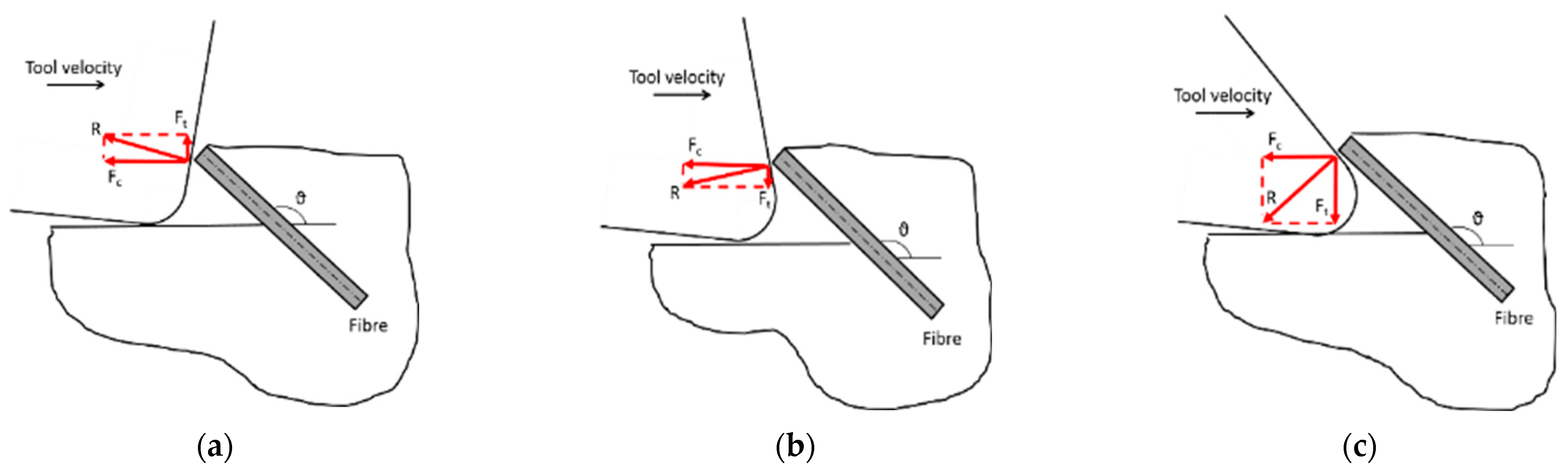
Figure 28.
The thrust force component’s influence is schematically illustrated for (a) negative rake angle, (b) low positive rake angle, and (c) large positive rake angle.
Figure 28.
The thrust force component’s influence is schematically illustrated for (a) negative rake angle, (b) low positive rake angle, and (c) large positive rake angle.
Table 1.
Properties of fibre and matrix phases in UD-CFRP [
19,
20].
Table 1.
Properties of fibre and matrix phases in UD-CFRP [
19,
20].
| Material | Property |
|---|
| Carbon fibre—T800S | Fibre diameter: 5 μm |
| Volume of fibre: 56.6% |
| Elastic modulus: 294 GPa |
| Tensile ultimate strength: 5.88 GPa |
| Density of fibre: 1.80 g/cm3 |
| HexPly® M21 | Elastic modulus: 172 GPa |
| Tensile ultimate strength: 3 GPa |
| Compression modulus: 136 GPa |
| Compression ultimate strength: 1.67 GPa |
| Shear modulus: 5 GPa |
| Shear strength: 79 MPa |
Table 2.
Machining parameters applied to experiments.
Table 2.
Machining parameters applied to experiments.
| Factor | Symbol | | Levels | |
|---|
| Orientation of Fibre (degrees) | θ | 0° | 45° → 90° | 135° |
| Cutting speed (mm/min) | | | 12 → 570 | 1100 |
| Rake angle (degrees) | α | | −10° → 10° | 30° |
| Depth of cut (µm) | DOC | | 50 → 100 | 150 |
Table 3.
The orthogonal cutting experiments.
Table 3.
The orthogonal cutting experiments.
| Orientation of Fibre | Rake Angle | Cutting Speed | Depth of Cut | Exp. No |
|---|
| (Degrees) | Degrees | (mm/min) | (µm) | |
| | | 12 | 50/100/150 | 1 |
| | −10° | 570 | 50/100/150 | 2 |
| | | 1100 | 50/100/150 | 3 |
| | | 12 | 50/100/150 | 4 |
| θ = 0° | 10° | 570 | 50/100/150 | 5 |
| | | 1100 | 50/100/150 | 6 |
| | | 12 | 50/100/150 | 7 |
| | 30° | 570 | 50/100/150 | 8 |
| | | 1100 | 50/100/150 | 9 |
| | | 12 | 50/100/150 | 10 |
| | −10° | 570 | 50/100/150 | 11 |
| | | 1100 | 50/100/150 | 12 |
| | | 12 | 50/100/150 | 13 |
| θ = 45° | 10° | 570 | 50/100/150 | 14 |
| | | 1100 | 50/100/150 | 15 |
| | | 12 | 50/100/150 | 16 |
| | 30° | 570 | 50/100/150 | 17 |
| | | 1100 | 50/100/150 | 18 |
| | | 12 | 50/100/150 | 19 |
| | −10° | 570 | 50/100/150 | 20 |
| | | 1100 | 50/100/150 | 21 |
| | | 12 | 50/100/150 | 22 |
| θ = 90° | 10° | 570 | 50/100/150 | 23 |
| | | 1100 | 50/100/150 | 24 |
| | | 12 | 50/100/150 | 25 |
| | 30° | 570 | 50/100/150 | 26 |
| | | 1100 | 50/100/150 | 27 |
| | | 12 | 50/100/150 | 28 |
| | −10° | 570 | 50/100/150 | 29 |
| | | 1100 | 50/100/150 | 30 |
| | | 12 | 50/100/150 | 31 |
| θ = 135° | 10° | 570 | 50/100/150 | 32 |
| | | 1100 | 50/100/150 | 33 |
| | | 12 | 50/100/150 | 34 |
| | 30° | 570 | 50/100/150 | 35 |
| | | 1100 | 50/100/150 | 36 |
Table 4.
Experimental results for RMS design.
Table 4.
Experimental results for RMS design.
| Fibre Orientation (Degrees) | Rake Angle (Degrees) | Cutting Speed (mm/min) | Depth of Cut (mm) | Cutting Force (N/mm) | Thrust Force (N/mm) | Surface Roughness (Ra, µm) | Damage Depth (µm) | Bounce Back (µm) | N |
|---|
| | | 12 | 50 | 38.3 | 52.9 | 0.56 | 117.2 | 24 | 10 |
| | −10 | 12 | 150 | 113.4 | 81.7 | 0.62 | 292 | 24 | 10 |
| | | 1100 | 50 | 25.5 | 50.5 | 0.3 | 117 | 23.9 | 12 |
| | | 1100 | 150 | 78.4 | 80.44 | 0.47 | 182.5 | 30 | 12 |
| θ = 45° | 10 | 570 | 100 | 60.2 | 82.9 | 1.02 | 328.5 | 16.1 | 14 |
| | | 12 | 50 | 62.4 | 115 | 0.45 | 162.3 | 31.6 | 16 |
| | 30 | 12 | 150 | 102 | 122.7 | 1.37 | 328.5 | 36.4 | 16 |
| | | 1100 | 50 | 61.63 | 117 | 0.54 | 122.55 | 20.7 | 18 |
| | | 1100 | 150 | 90.14 | 124.7 | 1.11 | 255.47 | 23.59 | 18 |
| | −10 | 570 | 100 | 93.64 | 66.27 | 1.06 | 55.235 | 34.7 | 20 |
| | | 12 | 100 | 103.1 | 66.26 | 0.85 | 760.24 | 23.43 | 22 |
| | | 570 | 50 | 78.5 | 60.2 | 0.52 | 245,098 | 8.4 | 23 |
| | | 570 | 100 | 131.9 | 44.6 | 2.31 | 2043.8 | 19.54 | 23 |
| θ = 90° | 10 | 570 | 100 | 157.9 | 35.72 | 2.73 | 2549.02 | 28.18 | 37 |
| | | 570 | 100 | 140.6 | 56.67 | 1.73 | 980,392 | 7.49 | 38 |
| | | 570 | 150 | 202.7 | 53.17 | 2.81 | 2549.02 | 12.61 | 23 |
| | | 1100 | 100 | 147.3 | 54.18 | 1.96 | 985.4 | 15.14 | 24 |
| | 30” | 570 | 100 | 129.6 | 55.29 | 3.2 | 1240.88 | 29.25 | 26 |
| | | 12 | 50 | 124 | 42.1 | 18.5 | 1372.55 | 194.159 | 28 |
| | −10 | 12 | 150 | 211.7 | 72.46 | 29.16 | 4901.96 | 413.12 | 28 |
| | | 1100 | 50 | 165 | 49.5 | 17.72 | 2745.1 | 159.98 | 30 |
| | | 1100 | 150 | 200.5 | 72.87 | 43.29 | 4411.76 | 295.304 | 30 |
| | 10 | 570 | 100 | 214.2 | 27.88 | 19.02 | 2352.94 | 55.14 | 32 |
| | | 12 | 50 | 189 | -24 | 5.83 | 1960.78 | 0 | 34 |
| | 30 | 12 | 150 | 220.5 | -37.2 | 14.7 | 3000 | 0 | 34 |
| | | 1100 | 50 | 147 | -20 | 6.11 | 1431.37 | 0 | 36 |
| | | 1100 | 150 | 185.1 | -29.9 | 14.74 | 2549.02 | 0 | 36 |
Table 5.
Influence of process parameters and interactions on various response measures based on p-value. (bold numbers are those with less than 0.05).
Table 5.
Influence of process parameters and interactions on various response measures based on p-value. (bold numbers are those with less than 0.05).
| Process Parameters | Cutting Force | Thrust Force | Damage Depth | Surface Roughness | Bounce Back |
|---|
| Fibre orientation () | <0.0001 | <0.0001 | <0.0001 | <0.0001 | 0.0004 |
| Rake angle () | 0.1930 | 0.0012 | 0.1799 | 0.0008 | <0.0001 |
| Cutting velocity () | 0.5353 | 0.8442 | 0.9714 | 0.3409 | 0.3438 |
| Depth of cut () | 0.0001 | 0.0174 | 0.0013 | 0.0017 | 0.0616 |
| 0.8344 | <0.0001 | 0.0783 | 0.0003 | <0.0001 |
| 0.8941 | 0.5964 | 0.9605 | 0.3111 | 0.4457 |
| 0.9728 | 0.2285 | 0.0141 | 0.0023 | 0.0687 |
| 0.4595 | 0.7523 | 0.4614 | 0.3628 | 0.4858 |
| 0.2498 | 0.0032 | 0.2455 | 0.2198 | 0.0606 |
| 0.4185 | 0.9422 | 0.4471 | 0.3058 | 0.6491 |
| | | | 0.0022 | 0.3061 |
| | | | 0.9083 | 0.3703 |
| | | | 0.8241 | 0.6588 |
| | | | 0.9205 | 0.9049 |
Table 6.
Models’ summary statistics.
Table 6.
Models’ summary statistics.
| Output Variable | Model Fit | R-Squared |
|---|
| Cutting force | 2FI | 0.89 |
| Thrust force | 2FI | 0.98 |
| Damage depth | 2FI | 0.87 |
| Surface roughness | Quadratic | 0.95 |
| Bounce back | Quadratic | 0.91 |
Table 7.
Model coefficients for each output variable.
Table 7.
Model coefficients for each output variable.
| Coeff. | Cutting Force | Thrust Force | Damage Depth | Surface Roughness | Bounce Back |
|---|
| a | −62.34078 | 71.16719 | −1195.60251 | 20.61315 | 28.33589 |
| b | 1.27039 | −0.34785 | 12.29852 | 0.63961 | −1.43711 |
| c | 1.44578 | 3.82401 | 43.43755 | 0.39097 | 4.34509 |
| d | 0.012795 | −3.61647 × 10⁻³ | 0.51158 | −2.61787 × 10⁻³ | −0.021271 |
| e | 0.75006 | 0.29579 | −1.38042 | -0.056215 | −0.37485 |
| f | −1.40208 × 10⁻³ | −0.039019 | −0.32295 | −4.77887 × 10⁻³ | −0.074506 |
| g | 3.28074 × 10⁻⁵ | 4.79473 × 10⁻⁵ | 3.17758 × 10⁻⁴ | 3.64457 × 10⁻⁵ | −3.42804 × 10⁻⁴ |
| h | −9.13889 × 10⁻⁵ | −1.20889 × 10⁻³ | 0.18927 | 1.44424 × 10⁻³ | 9.45784 × 10⁻³ |
| i | −4.13660 × 10⁻⁴ | 6.41085 × 10⁻⁵ | −0.010718 | −7.33613 × 10⁻⁵ | 7.03574 × 10⁻⁴ |
| m | −7.09187 × 10⁻³ | −7.51125 × 10⁻³ | −0.18628 | −1.09216 × 10⁻³ | −0.022043 |
| n | −1.81319 × 10⁻⁴ | −5.88235 × 10⁻⁶ | −4.42734 × 10⁻³ | 3.31766 × 10⁻⁵ | −1.82604 × 10⁻⁴ |
| p | 0 | 0 | 0 | 4.01949 × 10⁻³ | 0.014014 |
| q | 0 | 0 | 0 | 6.19128 × 10⁻⁴ | 0.061777 |
| r | 0 | 0 | 0 | −1.61521 × 10⁻⁶ | 4.06196 × 10⁻⁵ |
| s | 0 | 0 | 0 | −8.57595 × 10⁻⁵ | 1.29633 × 10⁻³ |
Table 8.
Optimal combinations of cutting velocity and rake angle for different fibre orientations at a constant depth of cut of 100 µm.
Table 8.
Optimal combinations of cutting velocity and rake angle for different fibre orientations at a constant depth of cut of 100 µm.
| θ | α | Cutting Speed | | | Surface Roughness | Damage Depth |
|---|
| | | (mm/min) | (N/mm) | (N/mm) | (µm) | (µm) |
|---|
| 45° | −10° | 366.82 | 62.78 | 65.49 | 0.3 | 38.53 |
| 90° | 30° | 1100 | 128.22 | 47.63 | 0.3 | 1102 |
| 135° | 30° | 1100 | 184.70 | −23.76 | 12 | 2087 |


 ,
, 


