Review

Research Status of and Prospects for 3D Printing for Continuous Fiber-Reinforced Thermoplastic Composites

1
Key Laboratory of Manufacturing Equipment of Shaanxi Province, Xi’an University of Technology, Xi’an 710048, China
2
School of Mechanical Engineering, Northwestern Polytechnical University, Xi’an 710072, China
*
Author to whom correspondence should be addressed.
Polymers 2023, 15(17), 3653; https://doi.org/10.3390/polym15173653
Submission received: 6 June 2023 / Revised: 8 August 2023 / Accepted: 11 August 2023 / Published: 4 September 2023
(This article belongs to the Special Issue Polymer-Based Flexible Materials)

Abstract

:
Continuous fiber-reinforced thermoplastic composites (CFRTPCs) have advantages such as high specific strength, high specific modulus, corrosion resistance, and recyclability and are widely used in the fields of aerospace, rail transit, new energy, and so on. However, traditional methods for preparing CFRTPCs, such as placement and molding, rely more on forming molds, resulting in high manufacturing costs and a slow response speed, which limits the promotion and application of the new generation of CFRTPCs with complex configurations and designable performance. Three-dimensional printing can efficiently create products with multiple materials, complex structures, and integrated functions, introducing new ways and opportunities for the manufacturing of CFRTPCs. However, poor mechanical properties are the bottleneck problem in achieving 3D printing of CFRTPCs. This paper summarizes the research status of the fused deposition modeling (FDM) 3D printing process and the corresponding mechanical properties of CFRTPCs. The focus is on analyzing the influences of the FDM process parameters, such as the material type, printing temperature, speed parameters, layer thickness, scanning space, stacking direction, and fiber volume content, on the mechanical properties of CFRTPCs. Finally, the main problems and future prospects of current CFRTPCs-FDM are analyzed and forecasted, providing new references and ideas for 3D printing of high-performance CFRTPCs.

1. Introduction

Continuous Fiber-Reinforced Thermoplastic Composites (CFRTPCs), composed of reinforcing fiber and matrix resin through certain forming processes, have advantages such as high specific strength, high specific modulus, corrosion resistance, fatigue resistance, recyclability, good damping and shock absorption, designable performance, and multifunctional integration [1,2,3]. As shown in Figure 1, they have been widely used in various fields such as aviation, aerospace, rail transit, new energy vehicles, nuclear power, wind energy, and so on [4,5].
The traditional process methods for preparing CFRTPCs (such as compression molding [6], resin transfer molding [6], automated winding/placement [7], autoclave molding [8], etc., as shown in Figure 2) are excessively dependent on the forming die, with high manufacturing costs and slow response speeds. However, with the continuous promotion and application of composite materials, the design of the appearance of products is becoming increasingly complex, the accuracy requirement is becoming higher, and the market rapid response and lightweight requirement are becoming more stringent. Relying on traditional process methods, it is difficult to meet the above technical and efficiency requirements of complex high-performance CFRTPCs.
Three-dimensional printing can directly build products with multiple materials, complex structures, and integrated functions, according to the CAD model without the need for traditional mold development and mechanical processing, which makes the forming not limited by the shape of the parts and the mold, and greatly shortens the product development cycle. Therefore, 3D printing of CFRTPCs has become a new generation of composite material forming methods, namely composites 2.0 [4,5,9,10].
Applying 3D printing technology to the field of forming CFRTPCs can fully leverage the manufacturing advantages of 3D printing and the performance advantages of composite materials [11], which can truly achieve the transformation of the design and manufacturing philosophy of CFRTPCs from “design for manufacturing” to “manufacturing for design”. Fused deposition modeling (FDM) is a widely used 3D printing method due to its advantages of low cost, easy operation, and relatively simple process. This paper analyzes and summarizes the current research status of CFRTPCs-FDM. Firstly, the process principles, classification, and corresponding mainstream printing equipment of CFRTPCs-FDM are analyzed and introduced. Secondly, a detailed discussion is conducted on the impact mechanism and research status of the FDM process parameters on the mechanical properties of CFRTPCs. Finally, based on the current research status, the main problems, future research directions, and development trends of CFRTPCs-FDM are considered and prospected.

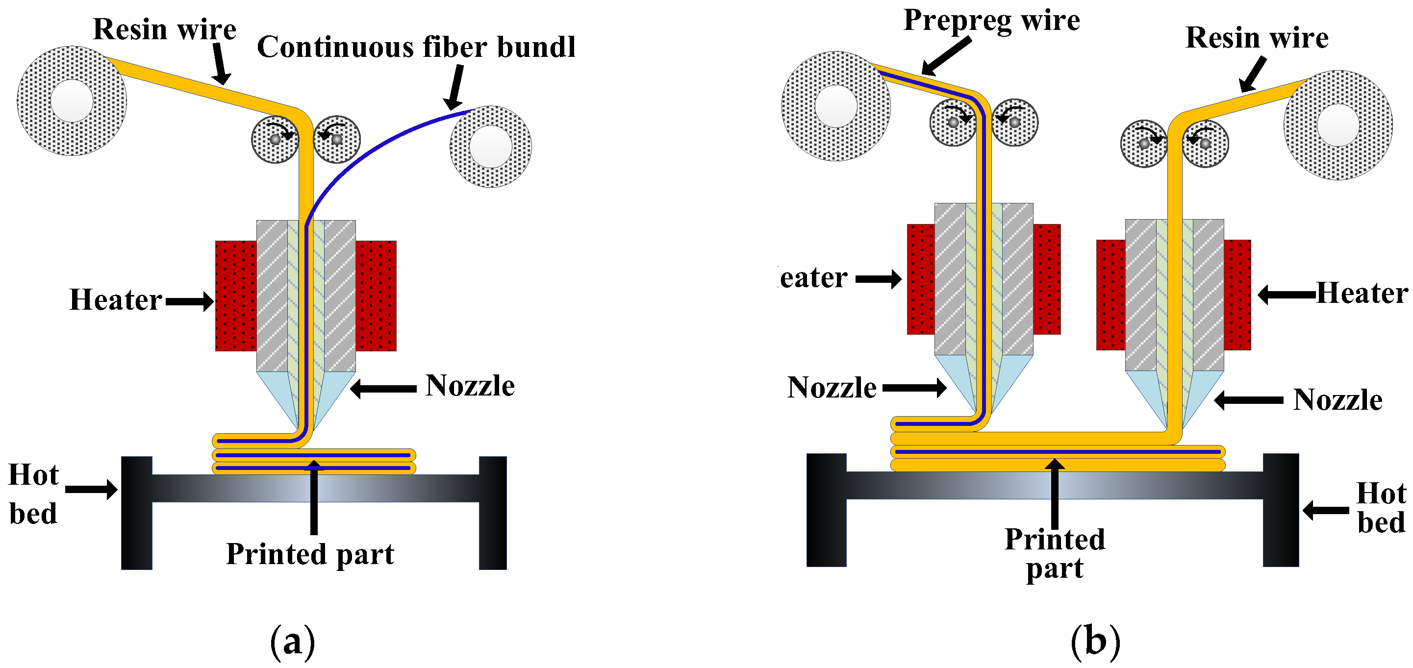
2. CFRTPCs-FDM Principles and Equipment

According to the different ways of embedding continuous fibers into the resin matrix, the process principles of CFRTPCs-FDM can be mainly divided into two categories: online infiltration co-extrusion and offline prepreg double nozzles extrusion.
Online infiltration co-extrusion: As shown in Figure 3a, continuous fiber dry bundles and pure resin wires are used as raw materials, and both are fed into the same printing head. The fibers are embedded in the resin and soaked inside the printing head and then extruded and deposited on the current printing layer together. The infiltrating time and pressure inside the printing head directly affect the infiltrating effect of fibers/resins. By controlling the feeding speed of resin wires, the fiber volume content of the part can be adjusted.
Offline prepreg double nozzles extrusion: As shown in Figure 3b, a prepreg wire premade of continuous fibers and resin is used as the raw material, and the prepreg is melted, extruded, and deposited in one of the printing nozzles. The other printing head uses pure resin wire as the raw material. On the one hand, the pure matrix resin is melted and deposited to form a good bonding interface between the prepreg layers required by the design, and on the other hand, the pure matrix resin can be used to print the outer frame of the product or fill the internal space to obtain a better appearance and dimensional accuracy. By controlling the printing amount of the pure matrix resin, the fiber volume content can be indirectly adjusted.
The representative printer of online infiltration co-extrusion is the Combot series printing equipment developed by Xi’an Jiaotong University, as shown in Figure 4a; the representative printer of offline prepreg double nozzles extrusion is the Mark series printing equipment developed by the MarkForged Company (Waltham, MA, USA), as shown in Figure 4b.
The principle of CFRTPCs-FDM determines the structural form of the 3D printers. For CFRTPCs with the same component, using different process principles and printer structures results in significant differences in the degree of infiltration between the fibers and resins and significant differences in the mechanical properties of the parts. Therefore, when selecting the process principle and corresponding printing equipment, factors such as printing cost, printing efficiency, material performance, and molding quality should be comprehensively considered [12,13].
At present, CFRTPCs-FDM is still in its early development stages, with problems such as low forming accuracy and poor mechanical properties caused by high porosity and multiple interfaces [14], as shown in Figure 5. Figure 6 shows the fracture surface SEM micrographs of the CF/ABS composites printed by FDM and by compression molding, respectively, indicating that pore enlargement is evident around the fibers in the FDM sample, while no significant enlargement is seen in the compression molding sample. How to efficiently integrate CFRTPCs with AM and achieve rapid and accurate additive manufacturing of CFRTPCs is of great significance.

3. Influence of the Process Parameters on the Mechanical Properties

The schematic diagram of CFRTPCs-FDM and its process parameters based on online infiltration co-extrusion is shown in Figure 7. The mapping relationship between the process parameters and the mechanical properties is the basis for parameter optimization. Table 1 summarizes the relationship that has been studied in the existing literature, where the mechanical properties include tensile, bending, shear, and compression, and the process parameters include the printing temperature, speed parameters, printing layer thickness, scanning space, etc.

3.1. Material Type

CFRTPCs are composed of two types of materials: a matrix phase thermoplastic resin and a reinforcing phase continuous fiber. The continuous fiber is used to enhance the load-bearing capacity, while the resin is used to support and protect the fibers and evenly transmit and distribute loads. Currently, for CFRTPCs-FDM, commonly used fibers include carbon fiber (CF), glass fiber (GF), and Kevlar fiber (KF); commonly used thermoplastic resins include polylactic acid (PLA), acrylonitrile butadiene styrene copolymers (ABS), polyamide (commonly known as nylon) (PA), and polyether ether ketone (PEEK). Table 2 shows the mechanical parameters of the materials.
Different fiber/resin combinations result in significant differences in the mechanical properties of the 3D printed CFRTPCs due to the different interphase interface properties. Oztan et al. [16] used CF and KF to enhance the nylon matrix and found that the tensile strength of the 3D printed part increased by 2 to 11 times, reaching the strength level of aviation aluminum alloys. In the literature [17,18,19,22], CFRTPCs were 3D printed with continuous CF, GF, and KF as reinforcing phases and nylon as the matrix phase, respectively. It was found that the mechanical properties of the CF-reinforced composites were the best, followed by GF, and KF was the worst. In addition to the differences in the properties of the fibers themselves, Dickson et al. [17], Caminero et al. [21], and Goh et al. [20,31] also found in the study of the interlayer mechanical properties that the interfacial bonding performance between the reinforced fibers and the matrix is an important factor affecting the mechanical properties of the workpiece.
The above research indicates that the material properties of fibers and resins, as well as their interfacial properties, are important factors affecting the mechanical properties of CFRTPCs. To improve the mechanical properties, on the one hand, efforts can be made to develop high-performance fibers and matrices and expand the material system; on the other hand, fiber modification technology can be combined to make the fiber surface rougher or undergo chemical reactions to generate new polar groups to promote matrix impregnation of the fibers and improve the interfacial bonding performance between the fibers and the matrix.

3.2. Printing Temperature

The printing temperature directly affects the melt flow performance of the matrix resin after heating, affecting the mechanical properties of the CFRTPCs from two aspects:
(1)
Influence on the infiltration between fibers and resins
The printing temperature is too low, resulting in high viscosity and poor fluidity during resin melting, making it difficult to complete the printing work. The increase in printing temperature enhances the resin melt fluidity, making it easier to enter the interior of the fiber bundle, improving the degree of infiltration between the fibers and resin, and thus improving the forming quality of the workpiece. However, excessive temperature can easily lead to strong resin fluidity and even decomposition and vaporization, which is not conducive to 3D forming. In general, the reasonable range for 3D printing temperature selection is above the glass transition temperature of the resin material and below the thermal decomposition temperature. Tian et al. [27] confirmed this through experiments. When the printing temperature is below 180 °C, the fluidity of the PLA is poor, and the nozzle is prone to blockage. When the temperature is above 240 °C, PLA is in liquid form and naturally flows out from the nozzle, which cannot guarantee printing accuracy. Based on comprehensive analysis, it can be concluded that the reasonable printing temperature for PLA is 180–230 °C. Shan et al. [25] found that when the printing temperature increased from 180 °C to 220 °C, the tensile strength of the specimen increased by about 20% (188 MPa vs. 225 MPa), and the bending strength increased by about 8% (274 MPa vs. 296 MPa).
(2)
Influence on the multi-interface bonding performance of CFRTPCs
Three-dimensional printed CFRTPCs have multiple interfaces, as shown in Figure 6, mainly including the interphase interface of fiber/resin, the interface between adjacent layers, and the interface between adjacent wires in the layer, among which the latter two belong to the resin wire interface.
(1)
For the fiber/resin interface, a reasonable printing temperature is beneficial for the resin matrix to remain above the glass transition temperature for a relatively long time, which is conducive to the full infiltration between the resin and the fiber bundle, thereby obtaining a phase interface with good performance.
(2)
For the interface between resin wires, as shown in Figure 8, the formation process of the wire interface includes three stages: the contact between the wire surfaces, the radial growth between adjacent wires, and the diffusion and fusion of molecular chains. A reasonable printing temperature is conducive to the full diffusion and fusion of molecular chains near the contact surface of the printed wire, promoting the radial growth of the wire contact surface, and finally forming a good wire interface.

3.3. Speed Parameters

The speed parameters include the printing speed and substrate feeding speed. The printing speed refers to the movement speed of the printing head, which is also the wire output speed of continuous fibers at the printer nozzle. The printing speed determines the forming efficiency of the workpiece and the soaking time of the continuous fibers and molten resin in the printing head. For online infiltration co-extrusion, the substrate feeding speed refers to the volume of resin material entering the printing head per unit time. Since the nozzle inner diameter remains unchanged, the substrate feeding speed determines the impregnation pressure between the fiber and the molten matrix, and to some extent determines the fiber volume content of the product.
When determining the speed parameters, it is necessary to comprehensively consider the nozzle diameter and the type and performance of the fiber and resin. In general, a lower printing speed and a higher substrate feeding speed can improve the impregnation pressure and degree, which is beneficial for improving the interfaces’ bonding performance. However, too low a printing speed can prolong the heating time of the resin matrix inside the nozzle, causing thermal decomposition of the resin and preventing normal printing. Excessive substrate feeding speed may cause the molten resin to overflow from the nozzle, affecting the normal printing work. Zeng et al. [28] also found that the bending strength and modulus of the specimen decreased with the increasing printing speed (1 mm–6 mm/s). Dou et al. [23] concluded that the tensile strength and modulus of the CF-reinforced PLA specimens decreased by 7.70% (200.43 MPa vs. 185 MPa) and 17.07% (23.31 GPa vs. 19.33 GPa), respectively, by increasing the printing speed from 50 mm/min to 400 mm/min.

3.4. Layer Thickness

As shown in Figure 5, the printing layer thickness refers to the spatial distance between the nozzle and the previous printing layer. A smaller layer thickness is beneficial for enhancing the compaction effect of the nozzle on the material during the process [37,44,45]. On the one hand, it can promote the resin in the molten state to better infiltrate the reinforced fibers and improve the fiber/matrix interface performance. On the other hand, it is also beneficial for improving the interface performance between adjacent printing wires within and between layers. At the same time, the layer thickness also affects the fiber volume content and porosity in the material. As the thickness decreases, the fiber volume content of the product shows an upward trend, and the corresponding porosity decreases.
For 3D printed CFRTPCs, Shan et al. [25] found that with the increase in the layer thickness (0.8–1.2 mm), the tensile strength and bending strength of the workpiece decreased by 33.82% (253.28 MPa vs. 167.63 MPa) and 37.17% (224.78 MPa vs. 141.22 MPa), respectively. Tian et al. [27] found that with the increase in the thickness (0.3–0.8 mm), the bending strength and modulus decreased by 58.9% and 66.3%, respectively. Hu et al. [29] found in their study that the thickness has the most significant impact on the bending performance of composite materials. As the thickness decreases, the bending strength and modulus of the 3D printed continuous CF-reinforced PLA composite can reach 610.1 MPa and 40.1 GPa, respectively. The reduction in the pore defects and the increase in the fiber volume content in materials are the main reasons for the significant improvement in the bending performance. Ning et al. [24] also found that a decrease in the thickness can reduce the porosity of the composite, thereby improving the mechanical properties. Chacón et al. [18,21,22,46] found in 3D printing research that an increase in the layer thickness leads to a decrease in the printing efficiency, and the impact of the thickness on the material mechanical properties is also related to the specific material stacking direction and load action form. Ming et al. [33] found that when the printing layer thickness is large, weak compaction leads to poor interface bonding performance between adjacent layers. But when the thickness is too small, the strong compaction effect can lead to fiber breakage and printing nozzle blockage. Only when the thickness is reasonably selected, can the surface of composite materials be relatively flat, the material can have good fiber continuity and low porosity, and the mechanical properties of the composite are at their highest.
Therefore, when selecting the thickness of the printing layer, it is necessary to comprehensively consider the relationship between the material mechanical properties, printing accuracy, and printing efficiency and make a compromise.

3.5. Scanning Space

As shown in Figure 5, the scanning space refers to the center distance between adjacent printing wires within the same printing layer. Usually, to ensure sufficient contact between printed wires and reduce porosity, a certain overlap area is required. Different scanning spaces can lead to differences in overlap and contact pressure, which in turn affect the degree of fiber/resin infiltration and the multi-interface bonding performance. When the scanning space is too small and the overlapping proportion is too high, fiber wear and fracture occur in the printed structure. If the scanning spacing is too large, there is no overlap between the adjacent wires, and there are obvious pore defects. And the different scanning space also affects the fiber volume content and mechanical properties of the composites.
In the study of the 3D printing of CFRTPCs, Shan. et al. [25] found that with the increase in the scanning space (0.5–1.1 mm), the tensile strength and bending strength of the composites increased first and then decreased. When the scanning space was 0.65 mm, the mechanical property was the highest. When the scanning space was less than 0.65 mm, fiber wear, fracture and warpage occurred during printing, resulting in poor mechanical properties. When the space was greater than 0.65 mm, the increase in the scanning space reduced the impregnation degree and also caused the decrease in the fiber volume content, which led to the decrease in the mechanical strength. Tian et. al. [27,38] discussed the effect of the scanning space on the flexural properties in detail. It was found that with the increase in the scanning space (0.4–1.8 mm), the flexural strength and flexural modulus decreased by 60.7% and 79.3%, respectively. In summary, the scanning space has a significant effect on the mechanical properties of the composites.

3.6. Stacking Direction

According to the different geometric shapes and performance requirements of the parts, different stacking directions can be used to stack and accumulate materials layer by layer. The stacking direction is also an important factor affecting the mechanical properties of CFRTPCs. As shown in Figure 9, in the x-y-z coordinate system, the z-axis represents the stacking direction. It can be seen that the standard test pieces with the same geometric shape have various stacking directions such as a flat normal direction, a side legislative direction, and a straight legislative direction. Three-dimensional prints with different stacking directions have different microstructures and mechanical properties.
Currently, most research on the stacking direction is mainly based on experiments. Chacón et. al. [18,22,46] systematically studied the influence of the three stacking directions shown in Figure 7 on the mechanical properties of CFRTPCs. In terms of the tensile tests, the performance of stacking along the flat normal and side legislative directions was close to and good, while the performance of stacking along the straight legislative direction was poor. In terms of the bending and impact experiments, the performance of stacking along the lateral direction was the best, followed by the horizontal normal direction and the vertical normal direction. It is worth noting that the impact of the stacking methods on the mechanical properties varies under different loads [41]. The reasons can be summarized: (a) the microstructure of composites with different stacking directions is different, resulting in different bearing characteristics under different loads; (b) different stacking directions can also affect the fiber volume content; (c) different stacking directions may also lead to differences in the porosity of the composite materials.

3.7. Fiber Volume Content

Reinforcing fibers are the main load-bearing phase of CFRTPCs, and their volume content directly determines the part’s mechanical properties. Normally, an increase in fiber volume content results in a significant improvement in the mechanical properties. The commonly used methods for calculating fiber content include thermogravimetric analysis [16], geometric calculation [23,37], and image analysis [20,39]. At present, the fiber volume content of 3D printed CFRTPCs does not exceed 50% [11,17,19,47,48], which is lower than that of composite materials prepared by traditional processes. The low fiber volume content is one of the important reasons for the low mechanical properties of 3D printed CFRTPCs. Since in the 3D printing process, with the increase in the fiber volume content, the full infiltration of fibers becomes more difficult, this results in a decrease in the interfacial bonding strength between the fiber/resin phases of 3D printed composites. At the same time, it also introduces more pore defects in the material, ultimately having an adverse impact on the mechanical properties of the composite. Dickson et. al. [17] found that the tensile properties of 3D printed composite materials significantly improved with the increase in the fiber volume content within a certain range. However, when the fiber volume content exceeded a certain level, the improvement in the mechanical properties of the composite material decreased. Chacón et. al. [18,22] believe that an increase in fiber volume content will have two distinct effects on 3D printed composite materials: on the one hand, an increase in the fiber content will hinder the damage evolution in composite materials and play a positive role in improving the mechanical properties of the material; on the other hand, an increase in fiber content will make it more difficult for the fibers to fully infiltrate, leading to a decrease in the strength of the fiber/matrix interface and the introduction of more pore defects in the material, ultimately affecting the mechanical properties. It should be noted that the fiber volume content of 3D printed composite materials is still relatively low now, and with the increase in the fiber volume content, the sufficient infiltration of fibers cannot be effectively guaranteed, and the number of pore defects in the material also increases, which has adverse effects on the improvement of the mechanical properties of composite materials.
Therefore, in future research, on the one hand, effective methods to increase the fiber volume content of 3D printed composite materials should be further explored; on the other hand, in-depth research should also be conducted on how to improve the sufficient infiltration and high porosity of fibers under high fiber volume content, in order to ultimately achieve effective printing of high fiber volume content composite materials with good mechanical properties, meeting the application requirements of complex engineering structures for high-performance composite materials.

4. Improvement and Perfection for CFRTPCs-FDM

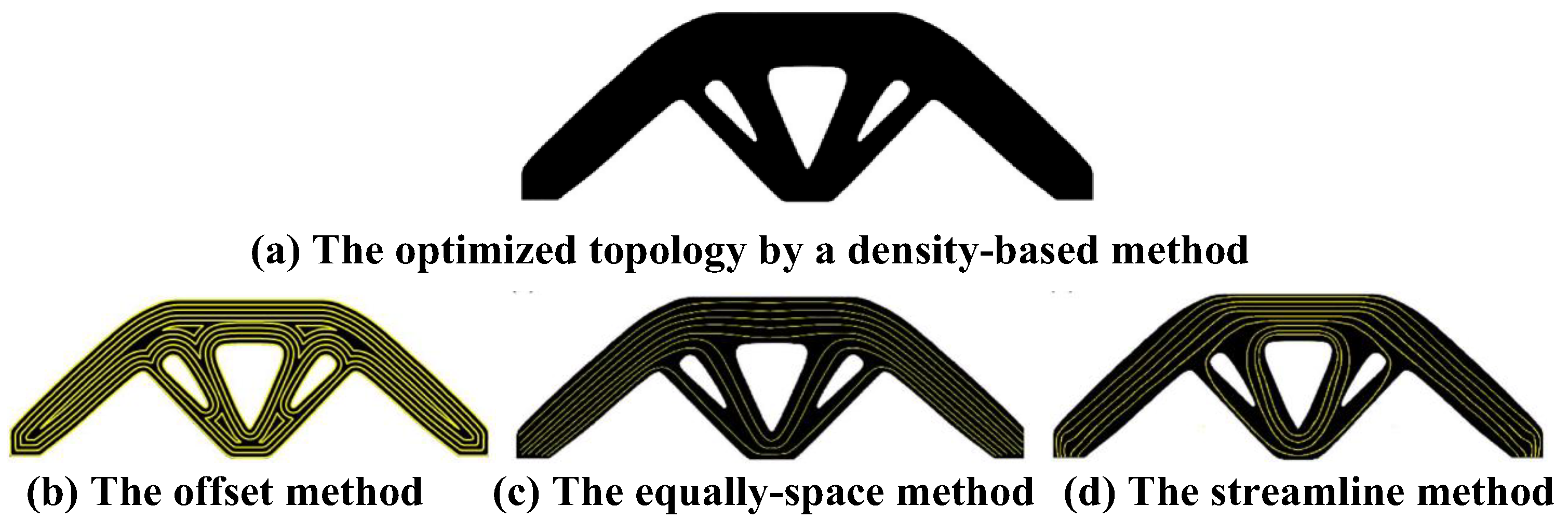
4.1. Structural Topology Optimization and Fiber Path Planning for CFRTPCs-FDM

Structural topology optimization is an important means to achieve lightweight in CFRTPCs-FDM products, and fiber path planning aims to determine the distribution of continuous fibers within the product. The main challenge of CFRTPCs-FDM structural topology optimization and fiber path planning is the coupling between structural design and the fiber distribution. Due to the anisotropic mechanical properties of fibers, the change in the fiber distribution caused by the shape change of composite materials should be fully considered in the topology optimization process. There are two main ideas for topology optimization and path planning of a CFRTPCs-FDM structure. One is sequential optimization, which first considers the overall topological shape and then considers the fibers distribution. For example, Li et al. [49] and Fedulov et al. [50] proposed a method of additive manufacturing of continuous carbon-fiber-reinforced nylon composites based on path planning. The topological optimization method is used to analyze the transmission path of the load in isotropic materials, and then the fiber trajectory design is carried out. This method considers the load transmission path of continuous fibers and the anisotropic mechanical properties. Papapetrou et al. [51] proposed a shape optimization method based on the density shape level set (Figure 10a) and gave three fiber filling methods: the offset method (Figure 10b), the equally spaced method (Figure 10c), and the streamline method (Figure 10d). These three methods can ensure the continuity of the fiber in the filling area.
The other is a parallel optimization that considers both the structural design and fiber distribution. For example, Lee et al. [52,53] proposed a topology optimization method for functionally graded composite structures, which can simultaneously design the optimal composite topology and spatially variable fiber distribution. A three-dimensional topology optimization method of continuous fibers based on the natural evolution method proposed by Alexander [54] can dynamically find the local optimal distribution of the material density and obtain a lighter structure. Huang et al. [55] proposed a design and manufacturing strategy integrating concurrent optimization of fiber orientation and structural topology for CFRTPCs, realized by ingenious path planning for the 3D printing process.

4.2. Assisted Processes and Devices for CFRTPCs FDM

(1)
Microwave-heating-assisted CFRTPCs-FDM
At present, the 3D printing of composite materials mainly adopts the traditional electric heating method to melt and then solidify and deposit, which has a long curing time and a high energy consumption. Li et al. [56] applied microwave technology to the 3D printing of composite materials and proposed a microwave-assisted heating CFRTPCs-FDM method, which uses microwaves to instantaneously volume heat CFRTPCs filaments. As shown in Figure 11, microwaves can quickly heat the fiber and quickly transfer heat to the resin, reducing the temperature change caused by the change in the printing speed, thereby improving the mechanical properties of the parts. At the same time, compared with the traditional heating method, the maximum printable wire diameter (1.75 mm vs. 5.48 mm) and the maximum printable speed (10 mm/s vs. 35 mm/s) are increased. Microwave-assisted CFRTPCs-FDM has the advantages of a fast heating speed, high thermal energy utilization, easy control, energy savings, and environmental protection.
(2)
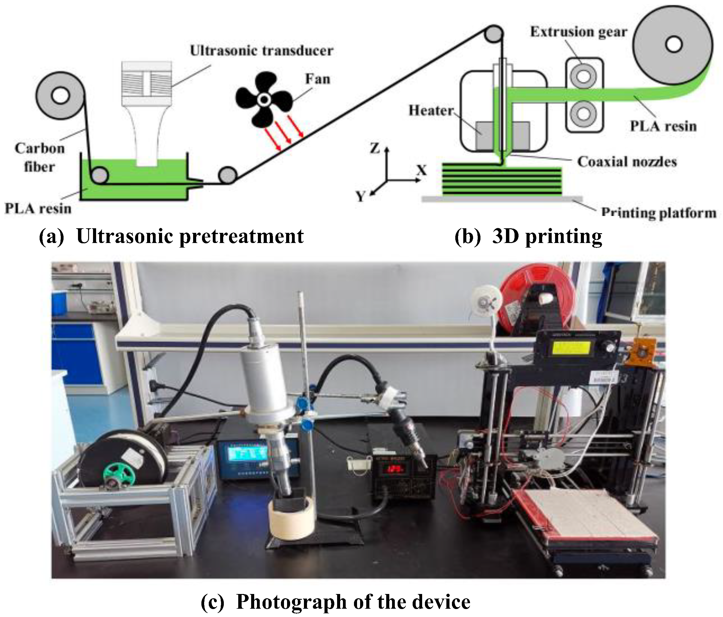
Ultrasonic-assisted CFRTPCs-FDM
Qiao et al. [57] proposed an ultrasonic-assisted fiber interface modification method to improve the wettability of fiber resin and the mechanical properties of CFRTPCs parts. In the 3D printing process of carbon fiber composites based on online infiltration co-extrusion, the carbon fiber is first guided to infiltrate once in the resin liquid with ultrasonic action, which reduces the porosity and improves the interfacial properties of the composites, as shown in Figure 12.
In order to improve the bonding between the resin and the fiber and reduce the porosity to improve the printing quality of CFRTPCs, in addition to the above process improvements, scholars have also proposed assisted measures such as substrate ultrasonic vibration assistance, laser melting assistance, roller pressure followup assistance, and hot pressing post treatment to improve the mechanical properties of CFRTPCs–FDM.

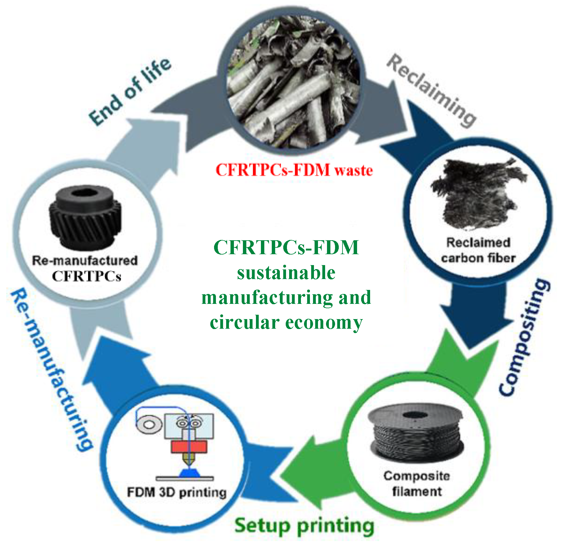
4.3. Recycling and Remanufacturing of CFRTPCs–FDM

With the wide application of CFRTPCs-FDM, the recycling and remanufacturing of waste composite parts has become a problem that must be faced. The recovery technologies of carbon fiber composite materials are divided into three categories: the physical recovery method, the energy recovery method, and the chemical recovery method. The physical recovery method is to mill, cut, or crush the waste composite materials to obtain short fibers, particles, powders, and other substances. This method has the advantages of being low cost, a simple process, and having no pollution, which is only suitable for uncontaminated composite waste parts, and the strength of the fiber is seriously reduced after treatment, and the reuse value is low. So, it can only be used as some fillers and cannot become a material with high purity requirements. The energy recovery method is to incinerate waste composite materials to obtain heat energy. However, this method causes secondary pollution, which should be avoided as much as possible. The technology that can really further recycle and reuse fibers is the chemical recovery method. The method is to degrade the resin matrix into small molecular compounds or oligomers, so as to achieve separation from fibers and fillers. It can not only recover the reinforced fibers but also recover the resin as raw material. It is the most promising recovery method at present [58].
The carbon fiber obtained by the chemical recovery method is usually in a messy and fluffy state, which is difficult to make into prepreg products with long tow lengths. Therefore, the recovered fiber is more suitable for nonwoven materials, cut into short fibers, or even ground into smaller particles or powders, added to the resin matrix for remanufacturing. At present, chopped-fiber-reinforced thermoplastic materials are widely used in the 3D printing of composite materials. Therefore, the recycled carbon fiber is particularly suitable for the 3D printing of chopped-fiber-reinforced composites. Figure 13 shows the CFRTPCs-FDM sustainable manufacturing and circular economy [59]. Compared with original fibers, using recycled fibers for 3D printing composite materials not only avoids the environmental pollution caused by waste materials but also helps to reduce the cost of the 3D printing composite materials.

5. Summary and Prospects

Compared with traditional preparation processes, the mechanical properties of 3D printed CFRTPCs are still relatively poor. This paper analyzes and reviews the current research status of the 3D printing of CFRTPCs from the perspective of mechanical properties, and draws the following conclusions:
(1)
The mechanical properties of 3D printed CFRTPCs are closely related to the properties of reinforcing fibers, matrix resins, and multiple interfaces. The influencing factors can be summarized into three aspects: the material type, the process principle, and the process parameters. The factors are coupled with each other, jointly determining the forming quality of CFRTPC products;
(2)
The impact of the above factors on the mechanical properties of 3D printed CFRTPCs is ultimately reflected in three aspects: the fiber volume content, the interface bonding strength, and the porosity. Compared with traditional forming processes, current 3D printed CFRTPCs still face prominent problems such as a low fiber volume content, a weak interface bonding strength, and a high porosity.
(3)
The fiber volume content is determined by a combination of speed parameters, layer thickness, scanning space, stacking direction, and so on. The pores of workpieces can be divided into macroscopic pores caused by the minimum bending radius or scanning overlap of the fibers and microscopic pores existing in continuous fibers, matrix resin, and interphase interface connections. Three-dimensional printed CFRTPCs have multiple interfaces: a fiber/resin interface and a resin interface between and within layers. Good interface bonding characteristics are conducive to reducing the porosity, improving the stress transfer efficiency, and interlaminar shear strength at the interface.
However, the existing research mainly focuses on analyzing the relevant factors through experimental methods along the lines of equipment development, experimental design, and result comparison, and exploring the optimal process methods and parameters under the relevant material types. In the future, research on CFRTPCs-FDM may focus on the following aspects:
(1)
It is necessary to explore the rheological and time-dependent behavior of composite materials in the multiple states of FDM from a more microscopic perspective, so as to construct a mechanical model that accurately describes the complex rheological properties of materials and reveal the melting deposition mechanism of CFRTPCs at the molecular/atomic level, to realize scientific prediction of the mechanical properties of 3D printed CFRTPCs.
(2)
The data show that 50% to 60% of the structural failures in composite materials are closely related to interlayer damage. The bonding ability of the CFRTPCs’ 3D printing multi-interface (interphase interface, interlayer, and inner layer wire interface) determines the interlaminar mechanical properties of the CFRTPCs to a large extent. Therefore, it is necessary to further study the interface cross scale coupling model of CFRTPCs-FDM, in order to reveal the regulatory mechanism of the interface from the microstructure to the macroscopic performance.
(3)
Researchers have established a relatively effective numerical simulation model for the traditional forming process of composite materials, achieving prediction and simulation of their mechanical behavior under typical load conditions. However, numerical simulations for the 3D printing of CFRTPCs are relatively lacking. Effective finite element and molecular dynamic models should be established based on the rheological mechanism and interface model of CFRTPCs-FDM to achieve effective simulation and prediction of 3D printed CFRTPCs properties.
(4)
The 3D printing of CFRTPCs has anisotropic characteristics, and the stacking direction and fiber orientation seriously affect the optimal load-bearing condition of the product. Therefore, it is necessary to carry out configuration design in combination with topology optimization, develop five-axis 3D printing equipment, adjust the stacking direction in real time, and use a path planning algorithm to realize the controllable layout of the fiber direction, so as to realize the integrated design and manufacturing of CFRTPCs in terms of “performance–configuration–process”.
(5)
It is necessary to explore and develop new process principles and improvement methods for the 3D printing of CFRTPCs, innovate CFRTPCs’ 3D printing equipment, and further improve the mechanical properties. Also needed is to develop new materials and improve the material system and, on the basis of the tensile, bending, and compression properties, further enrich the quality evaluation methods of the 3D printing of CFRTPCs, such as the impact properties, wear properties, creep properties, fatigue properties, and damage evolution laws.

Author Contributions

Conceptualization, Y.Y. and B.Y.; methodology, Y.Y. and Z.C.; validation, J.D. and W.C.; formal analysis, Z.C.; investigation, Y.Y. and B.Y.; resources, Y.Y.; data curation, Y.Y. and Z.C.; writing—original draft preparation, Y.Y.; writing—review and editing, Y.Y. and W.C.; visualization, Y.Y.; supervision, Z.C. and J.D.; project administration, Y.Y.; funding acquisition, Y.Y. All authors have read and agreed to the published version of the manuscript.

Funding

This work was supported by the Special Scientific Research Project of Shaanxi Education Department (19JK0594).

Institutional Review Board Statement

Not applicable.

Data Availability Statement

No new data were created or analyzed in this study. Data sharing is not applicable to this article.

Conflicts of Interest

The authors declare no conflict of interest.

References

  1. Minchenkov, K.; Vedernikov, A.; Safonov, A.; Akhatov, I. Thermoplastic Pultrusion: A Review. Polymers 2021, 13, 180. [Google Scholar] [CrossRef] [PubMed]
  2. Vedernikov, A.; Minchenkov, K.; Gusev, S.; Sulimov, A.; Zhou, P.; Li, C.; Xian, G.; Akhatov, I.; Safonov, A. Effects of the Pre-Consolidated Materials Manufacturing Method on the Mechanical Properties of Pultruded Thermoplastic Composites. Polymers 2022, 14, 2246. [Google Scholar] [CrossRef] [PubMed]
  3. Tucci, F.; Rubino, F.; Pasquino, G.; Carlone, P. Thermoplastic Pultrusion Process of Polypropylene/Glass Tapes. Polymers 2023, 15, 2374. [Google Scholar] [CrossRef] [PubMed]
  4. Tian, X.; Todoroki, A.; Liu, T.; Wu, L.; Hou, Z.; Ueda, M.; Hirano, Y.; Matsuzaki, R.; Mizukami, K.; Iizuka, K.; et al. 3D Printing of continuous fiber reinforced polymer composites: Development, application, and prospective. Chin. J. Mech. Eng. Addit. Manuf. Front. 2022, 1, 100016. [Google Scholar] [CrossRef]
  5. Liu, G.; Xiong, Y.; Zhou, L. Additive manufacturing of continuous fiber reinforced polymer composites: Design opportunities and novel applications. Compos. Commun. 2021, 27, 100907. [Google Scholar] [CrossRef]
  6. Santos, A.C.M.Q.S.; Monticeli, F.M.; Ornaghi, H.; Santos, L.F.D.P.; Cioffi, M.O.H. Porosity characterization and respective influence on short-beam strength of advanced composite processed by resin transfer molding and compression molding. Polym. Polym. Compos. 2021, 29, 1353–1362. [Google Scholar] [CrossRef]
  7. Smith, R.P.; Qureshi, Z.; Scaife, R.J.; El-Dessouky, H.M. Limitations of processing carbon fibre reinforced plastic/polymer material using automated fibre placement technology. J. Reinf. Plast. Compos. 2016, 35, 1527–1542. [Google Scholar] [CrossRef]
  8. Dong, C.; Zhou, J.; Ji, X.; Yin, Y.; Shen, X. Study of the curing process of carbon fiber reinforced resin matrix composites in autoclave processing. Procedia Manuf. 2019, 37, 450–458. [Google Scholar] [CrossRef]
  9. Ryosuke, M.; Masahito, U.; Masaki, N.; Tae-kun, J.; Hirosuke, A.; Keisuke, H.; Taishi, N.; Akira, T.; Yoshiyasu, H. Three-dimensional printing of continuous-fiber composites by in-nozzle impregnation. Sci. Rep. 2016, 6, 23058. [Google Scholar]
  10. Yang, C.; Tian, X.; Liu, T.; Cao, Y.; Li, D. 3D printing for continuous fiber reinforced thermoplastic composites: Mechanism and performance. Rapid Prototyp. J. 2017, 23, 209–215. [Google Scholar] [CrossRef]
  11. Justo, J.; Távara, L.; García-Guzmán, L.; París, F. Characterization of 3D printed long fibre reinforced composites. Compos. Struct. 2018, 185, 537–548. [Google Scholar] [CrossRef]
  12. Azarov, A.V.; Antonov, F.K.; Vasil’Ev, V.V.; Golubev, M.V.; Krasovskii, D.S.; Razin, A.F.; Salov, V.A.; Stupnikov, V.V.; Khaziev, A.R. Development of a two-matrix composite material fabricated by 3D printing. Polym. Sci. 2017, 10, 87–90. [Google Scholar] [CrossRef]
  13. Azarov, A.V.; Antonov, F.K.; Golubev, M.V.; Khaziev, A.R.; Ushanov, S.A. Composite 3D printing for the small size unmanned aerial vehicle structure. Compos. Part B Eng. 2019, 169, 157–163. [Google Scholar] [CrossRef]
  14. Heidari-Rarani, M.; Rafiee-Afarani, M.; Zahedi, A.M. Mechanical characterization of FDM 3D printing of continuous carbon fiber reinforced PLA composites. Composites 2019, 175, 107147. [Google Scholar] [CrossRef]
  15. Tekinalp, H.L.; Kunc, V.; Velez-Garcia, G.M.; Duty, C.E.; Love, L.J.; Naskar, A.K.; Blue, C.A.; Ozcan, S. Highly oriented carbon fiber–polymer composites via additive manufacturing. Compos. Sci. Technol. 2014, 105, 144–150. [Google Scholar] [CrossRef]
  16. Oztan, C.; Karkkainen, R.; Fittipaldi, M.; Nygren, G.; Roberson, L.; Lane, M.; Celik, E. Microstructure and mechanical properties of three dimensional-printed continuous fiber composites. J. Compos. Mater. 2019, 53, 271–280. [Google Scholar] [CrossRef]
  17. Dickson, A.N.; Barry, J.N.; McDonnell, K.A.; Dowling, D.P. Fabrication of Continuous Carbon, Glass and Kevlar fibre reinforced polymer composites using Additive Manufacturing. Addit. Manuf. 2017, 16, 146–152. [Google Scholar] [CrossRef]
  18. Chacón, J.M.; Caminero, M.A.; Núñez, P.J.; García-Plaza, E.; García-Moreno, I.; Reverte, J.M. Additive manufacturing of continuous fibre reinforced thermoplastic composites using fused deposition modelling: Effect of process parameters on mechanical properties. Compos. Sci. Technol. 2019, 181, 107688. [Google Scholar] [CrossRef]
  19. Al Abadi, H.; Thai, H.T.; Paton-Cole, V.; Patel, V.I. Elastic properties of 3D printed fibre-reinforced structures. Compos. Struct. 2018, 193, 8–18. [Google Scholar] [CrossRef]
  20. Goh, G.D.; Dikshit, V.; Nagalingam, A.P.; Goh, G.L.; Agarwala, S.; Sing, S.L.; Wei, J.; Yeong, W.Y. Characterization of mechanical properties and fracture mode of additively manufactured carbon fiber and glass fiber reinforced thermoplastics. Mater. Des. 2018, 137, 79–89. [Google Scholar] [CrossRef]
  21. Caminero, M.A.; Chacón, J.M.; García-Moreno, I.; Reverte, J.M. Interlaminar bonding performance of 3D printed continuous fibre reinforced thermoplastic composites using fused deposition modelling. Polym. Test. 2018, 68, 415–423. [Google Scholar] [CrossRef]
  22. Caminero, M.A.; Chacón, J.M.; García-Moreno, I.; Rodríguez, G.P. Impact damage resistance of 3D printed continuous fibre reinforced thermoplastic composites using fused deposition modelling. Compos. Part B Eng. 2018, 148, 93–103. [Google Scholar] [CrossRef]
  23. Dou, H.; Cheng, Y.; Ye, W.; Zhang, D.; Li, J.; Miao, Z.; Rudykh, S. Effect of Process Parameters on Tensile Mechanical Properties of 3D Printing Continuous Carbon Fiber-Reinforced PLA Composites. Materials 2020, 13, 3850. [Google Scholar] [CrossRef]
  24. Ning, F.; Cong, W.; Hu, Y.; Wang, H. Additive manufacturing of carbon fiber-reinforced plastic composites using fused deposition modeling: Effects of process parameters on tensile properties. J. Compos. Mater. 2017, 51, 451–462. [Google Scholar] [CrossRef]
  25. Fan, C.; Shan, Z.; Zou, G.; Li, Z. Interfacial Bonding Mechanism and Mechanical Performance of Continuous Fiber Reinforced Composites in Additive Manufacturing. Chin. J. Mech. Eng. 2021, 34, 1–11. [Google Scholar] [CrossRef]
  26. Wang, G.; Jia, Z.; Wang, F.; Dong, C.; Wu, B. Additive Manufacturing of Continuous Carbon Fiber Reinforced Thermoplastic Composites: An Investigation on Process-Impregnation-Property Relationship. In Proceedings of the ASME 2020 15th International Manufacturing Science and Engineering Conference, Online, 3 September 2020. [Google Scholar]
  27. Tian, X.; Liu, T.; Yang, C.; Wang, Q.; Li, D. Interface and performance of 3D printed continuous carbon fiber reinforced PLA composites. Compos. Part A Appl. Sci. Manuf. 2016, 88, 198–205. [Google Scholar] [CrossRef]
  28. Zeng, C.; Liu, L.; Bian, W.; Liu, Y.; Leng, J. 4D printed electro-induced continuous carbon fiber reinforced shape memory polymer composites with excellent bending resistance. Compos. Part B Eng. 2020, 194, 108034. [Google Scholar] [CrossRef]
  29. Hu, Q.; Duan, Y.; Zhang, H.; Liu, D.; Yan, B.; Peng, F. Manufacturing and 3D printing of continuous carbon fiber prepreg filament. J. Mater. Sci. 2018, 53, 1887–1898. [Google Scholar] [CrossRef]
  30. Chen, K.; Yu, L.; Cui, Y.; Jia, M.; Pan, K. Optimization of printing parameters of 3D-printed continuous glass fiber reinforced polylactic acid composites. Thin-Walled Struct. 2021, 164, 107717. [Google Scholar] [CrossRef]
  31. Goh, G.D.; Dikshit, V.; An, J.; Yeong, W.Y. Process-structure-property of Additively Manufactured Continuous Carbon Fiber Reinforced Thermoplastic: An Investigation of Mode I Interlaminar Fracture Toughness. Mech. Adv. Mater. Struct. 2020, 29, 1418–1430. [Google Scholar] [CrossRef]
  32. Mohammadizadeh, M.; Imeri, A.; Fidan, I.; Elkelany, M. 3D printed fiber reinforced polymer composites-Structural analysis. Compos. Part B Eng. 2019, 175, 107112. [Google Scholar] [CrossRef]
  33. Ming, Y.; Zhang, S.; Han, W.; Wang, B.; Duan, Y.; Xiao, H. Investigation on process parameters of 3D printed continuous carbon fiber-reinforced thermosetting epoxy composites. Addit. Manuf. 2020, 33, 101184. [Google Scholar] [CrossRef]
  34. Akhoundi, B.; Behravesh, A.H.; Saed, A.B. Mproving mechanical properties of continuous fiber-reinforced thermoplastic composites produced by FDM 3D printer. J. Reinf. Plast. Compos. 2019, 38, 99–116. [Google Scholar] [CrossRef]
  35. Dong, K.; Liu, L.; Huang, X.; Xiao, X. 3D printing of continuous fiber reinforced diamond cellular structural composites and tensile properties. Compos. Struct. 2020, 15, 112610. [Google Scholar] [CrossRef]
  36. Luo, M.; Tian, X.; Shang, J.; Zhu, W.; Li, D.; Qin, Y. Impregnation and Interlayer Bonding Behaviours of 3D-Printed Continuous Carbon-Fiber-Reinforced Poly-ether-ether-ketone Composites. Compos. Part A Appl. Sci. Manuf. 2019, 121, 130–138. [Google Scholar] [CrossRef]
  37. Hou, Z.; Tian, X.; Zhang, J.; Li, D. 3D printed continuous fibre reinforced composite corrugated structure. Compos. Struct. 2018, 184, 1005–1010. [Google Scholar] [CrossRef]
  38. Liu, T.; Tian, X.; Zhang, M.; Abliz, D.; Li, D.; Ziegmann, G. Interfacial performance and fracture patterns of 3D printed continuous carbon fiber with sizing reinforced PA6 composites. Compos. Part A Appl. Sci. Manuf. 2018, 114, 368–376. [Google Scholar] [CrossRef]
  39. Chabaud, G.; Castro, M.; Denoual, C.; Duigou, A.L. Hygromechanical properties of 3D printed continuous carbon and glass fibre reinforced polyamide composite for outdoor structural applications. Addit. Manuf. 2019, 26, 94–105. [Google Scholar] [CrossRef]
  40. Pyl, L.; Kalteremidou, K.A.; Hemelrijck, D.V. Exploration of specimen geometry and tab configuration for tensile testing exploiting the potential of 3D printing freeform shape continuous carbon fibre-reinforced nylon matrix composites. Polym. Test. 2018, 71, 318–328. [Google Scholar] [CrossRef]
  41. Araya-Calvo, M.; López-Gómez, I.; Chamberlain-Simon, N.; León-Salazar, J.L.; Guillén-Girón, T.; Corrales-Cordero, J.S.; Sánchez-Brenes, O. Evaluation of compressive and flexural properties of continuous fiber fabrication additive manufacturing technology. Addit. Manuf. 2018, 22, 157–164. [Google Scholar] [CrossRef]
  42. Pappas, J.M.; Thakur, A.R.; Leu, M.C.; Dong, X. A parametric study and characterization of additively manufactured continuous carbon fiber reinforced composites for high-speed 3D printing. Int. J. Adv. Manuf. Technol. 2021, 113, 2137–2151. [Google Scholar] [CrossRef]
  43. Li, H.; Wang, T.; Joshi, S.; Yu, Z. The quantitative analysis of tensile strength of additively manufactured continuous carbon fiber reinforced polylactic acid (PLA). Rapid Prototyp. J. 2019, 10, 1624–1636. [Google Scholar] [CrossRef]
  44. Yin, L.; Tian, X.; Shang, Z.; Wang, X.; Hou, Z. Characterizations of continuous carbon fiber-reinforced composites for electromagnetic interference shielding fabricated by 3D printing. Appl. Phys. A Mater. Sci. Process. 2019, 125, 266. [Google Scholar] [CrossRef]
  45. Chang, B.; Li, X.; Parandoush, P.; Ruan, S.; Shen, C.; Lin, D. Additive manufacturing of continuous carbon fiber reinforced poly-ether-ether-ketone with ultrahigh mechanical properties. Polym. Test. 2020, 88, 106563. [Google Scholar] [CrossRef]
  46. Chacón, J.M.; Caminero, M.A.; García-Plaza, E.; Núnez, P.J. Additive manufacturing of PLA structures using fused deposition modelling: Effect of process parameters on mechanical properties andtheir optimal selection. Mater. Des. 2017, 124, 143–157. [Google Scholar] [CrossRef]
  47. Mei, H.; Ali, Z.; Yan, Y.; Ali, I.; Cheng, L. Influence of mixed isotropic fiber angles and hot press on the mechanical properties of 3D printed composites. Addit. Manuf. 2019, 27, 150–158. [Google Scholar] [CrossRef]
  48. Werken, N.; Hurley, J.; Khanbolouki, P.; Sarvestani, A.N.; Tamijani, A.Y.; Tehrani, M. Design considerations and modeling of fiber reinforced 3D printed parts. Compos. Part B Eng. 2019, 160, 684–692. [Google Scholar] [CrossRef]
  49. Li, N.; Link, G.; Wang, T.; Ramopoulos, V.; Neumaier, D.; Hofele, J.; Walter, M.; Jelonnek, J. Path-designed 3D printing for topological optimized continuous carbon fibre reinforced composite structures. Compos. Part B Eng. 2020, 182, 107612. [Google Scholar] [CrossRef]
  50. Fedulov, B.; Fedorenko, A.; Khaziev, A.; Antonov, F. Optimization of parts manufactured using continuous fiber three-dimensional printing technology. Compos. Part B Eng. 2021, 227, 109406. [Google Scholar] [CrossRef]
  51. Papapetrou, V.S.; Patel, C.; Tamijani, A.Y. Stiffness-based optimization framework for the topology and fiber paths of continuous fiber composites. Compos. Part B Eng. 2020, 183, 107681. [Google Scholar] [CrossRef]
  52. Lee, J.; Kim, D.; Nomura, T.; Dede, E.M.; Yoo, J. Topology optimization for continuous and discrete orientation design of functionally graded fiber-reinforced composite structures. Compos. Struct. 2018, 201, 217–233. [Google Scholar] [CrossRef]
  53. Kim, D.; Lee, J.; Nomura, T.; Dede, E.M.; Yoo, J.; Min, S. Topology optimization of functionally graded anisotropic composite structures using homogenization design method. Comput. Methods Appl. Mech. Eng. 2020, 369, 113220. [Google Scholar] [CrossRef]
  54. Alexander, A. Safonov.3D topology optimization of continuous fiber-reinforced structures via natural evolution method. Compos. Struct. 2019, 215, 289–297. [Google Scholar]
  55. Huang, Y.; Tian, X.; Zheng, Z.; Li, D.; Malakhov, A.V.; Polilov, A.N. Multiscale concurrent design and 3D printing of continuous fiber reinforced thermoplastic composites with optimized fiber trajectory and topological structure. Compos. Struct. 2022, 285, 115241. [Google Scholar] [CrossRef]
  56. Li, N.; Guido, L.; John, J.; Morais Manuel, V.C.; Frank, H. Microwave additive manufacturing of continuous carbon fibers reinforced thermoplastic composites: Characterization, analysis, and properties. Addit. Manuf. 2021, 44, 102035. [Google Scholar] [CrossRef]
  57. Qiao, J.; Li, Y.; Li, L. Ultrasound-assisted 3D printing of continuous fiber-reinforced thermoplastic (FRTP) composites. Addit. Manuf. 2019, 30, 100926. [Google Scholar] [CrossRef]
  58. Scaffaro, R.; Di Bartolo, A.; Dintcheva, N.T. Matrix and Filler Recycling of Carbon and Glass Fiber-Reinforced Polymer Composites: A Review. Polymers 2021, 13, 3817. [Google Scholar] [CrossRef]
  59. Liu, W.; Huang, H.; Zhu, L.; Liu, Z. Integrating carbon fiber reclamation and additive manufacturing for recycling CFRP waste. Compos. Part B Eng. 2021, 215, 108808. [Google Scholar] [CrossRef]
Figure 1. CFRTPCs products and their applications in various fields.
Polymers 15 03653 g001
Figure 2. Traditional preparation processes for CFRTPCs.
Polymers 15 03653 g002
Figure 3. CFRTPCs-FDM principle. (a) Online infiltration co-extrusion; (b) Offline prepreg double nozzles extrusion.
Polymers 15 03653 g003
Figure 4. CFRTPCs-FDM printing equipment. (a) Combot-1TM; (b) MarkTwoTM.
Polymers 15 03653 g004
Figure 5. CFRTPCs-FDM printing equipment.
Polymers 15 03653 g005
Figure 6. Fracture surface SEM micrographs [15]. (a) CF/ABS composites printed by FDM; (b) CF/ABS composites formed by compression molding.
Polymers 15 03653 g006
Figure 7. CFRTPCs-FDM based on online infiltration co-extrusion.
Polymers 15 03653 g007
Figure 8. Multi-interface formation process of CFRTPCs-FDM.
Polymers 15 03653 g008
Figure 9. Schematic diagram of stacking direction.
Polymers 15 03653 g009
Figure 10. Stiffness-based optimization for the topology and fiber paths by Papapetrou.
Polymers 15 03653 g010
Figure 11. Illustration of the microwave printing head.
Polymers 15 03653 g011
Figure 12. A schematic diagram and a photograph of the ultrasonic-assisted CFRTPCs-FDM.
Polymers 15 03653 g012
Figure 13. CFRTPCs-FDM sustainable manufacturing and circular economy.
Polymers 15 03653 g013
Table 1. A list of the literature on the parameters and performance relationship of CFRTPCs.
Tensile/ElasticBending/FlexuralShearCompressiveImpactFracturePorosityFiber Content
Material typeRefs. [16,17,18,19,20]Refs. [17,18,20]Ref. [21] Ref. [22] Ref. [17]Ref. [17]
Printing temperatureRefs. [23,24,25,26]Refs. [26,27,28,29,30]Refs. [25,30] Ref. [30]Ref. [31]
Printing speedRefs. [23,24,26,32]Refs. [26,28,30,33]Ref. [4] Ref. [4]Ref. [9]
Layer thicknessRefs. [18,23,24,26,34,35]Refs. [18,26,27,29,30,33]Refs. [21,30,36]Ref. [37]Refs. [22,30] Refs. [26,27,35,36,37]
Scanning spaceRef. [23]Refs. [27,28,33,38]Ref. [36] Refs. [27,36]
Stacking orientationRef. [18]Ref. [18] Ref. [22]
Fiber orientationRefs. [17,19,39,40]Refs. [17,28,41]Ref. [40]Ref. [41] Ref. [17]Ref. [17]
Fiber contentRefs. [17,39,42]Refs. [17,41,43]Ref. [21]Refs. [41,43]Ref. [22] Ref. [17]
Table 2. Parameters of commonly used fibers and resins in CFRTPCs-FDM.
Material ParametersReinforcing FibersMatrix Resins
CFGFKFPLAABSPAPEEK
Density (g/cm3)1.27–1.761.51.21.251.041.11.32
Tensile Strength (MPa)70059061015.5–72.236–71.65497
Tensile Modulus (GPa)5421272.02–3.550.1–2.4130.942.8
Tensile Strain at Break (%)1.53.82.70.5–9.23–20260
Flexural Strength (MPa)47021019052–115.148–11032142
Flexural Modulus (GPa)5122262.392–4.931.917–2.5070.843.7
Flexural Strain at Break (%)1.21.12.1----
Compressive Strength (MPa)32014097----
Compressive Modulus (GPa)542128----
Compressive Strain at Break (%)0.7-1.5----
Disclaimer/Publisher’s Note: The statements, opinions and data contained in all publications are solely those of the individual author(s) and contributor(s) and not of MDPI and/or the editor(s). MDPI and/or the editor(s) disclaim responsibility for any injury to people or property resulting from any ideas, methods, instructions or products referred to in the content.

