Article

Special Packaging Materials from Recycled PET and Metallic Nano-Powders

1
Department of Electrical Measurements and Materials, Gheorghe Asachi Technical University, 700050 Iasi, Romania
2
National Institute for Research and Development in Electrical Engineering ICPE—CA, 030138 Bucharest, Romania
3
“Petru Poni” Institute of Macromolecular Chemistry, 41A Gr. Ghica Voda Alley, 700487 Iasi, Romania
*
Authors to whom correspondence should be addressed.
Polymers 2023, 15(15), 3161; https://doi.org/10.3390/polym15153161
Submission received: 26 June 2023 / Revised: 18 July 2023 / Accepted: 23 July 2023 / Published: 25 July 2023
(This article belongs to the Special Issue Metal Nanoparticles–Polymers Hybrid Materials III)

Abstract

:
The European methodology for plastics, as a feature of the EU’s circular economy activity plan, ought to support the decrease in plastic waste. The improvement of recycled plastics’ economics and quality is one important part of this action plan. Additionally, achieving the requirement that all plastic packaging sold in the EU by 2030 be recyclable or reusable is an important objective. This means that food packaging materials should be recycled in a closed loop at the end. One of the most significant engineering polymers is polyethylene terephthalate (PET), which is widely used. Due to its numerous crucial qualities, it has a wide variety of applications, from packaging to fibers. The thermoplastic polyolefin, primarily polyethylene and polypropylene (PP), is a popular choice utilized globally in a wide range of applications. In the first phase of the current experiment, the materials were obtained by hot pressing with the press machine. The reinforcer is made of Al nanopowder 800 nm and Fe nanopowder 790 nm and the quality of the recycled polymer was examined using Fourier transform infrared spectroscopy (FTIR), a scanning electron microscope (SEM), and differential scanning calorimetry (DSC). From DSC variation curves as a function of temperature, the values from the transformation processes (glass transition, crystallization, and melting) are obtained. SEM measurements revealed that the polymer composites with Al have smooth spherical particles while the ones with Fe have bigger rough spherical particles.

1. Introduction

As part of the EU’s circular economy action plan, the European Commission adopted a European strategy for plastics in 2018 [1]. The goal was to support, improve, and accelerate the implementation of measures to reduce plastic waste. Another significant objective is the requirement that all plastic packaging sold in the EU by 2030 either be reusable or can be recycled economically [2]. The question of how the European Union’s strategies for plastics in a circular economy will affect food safety and whether any associated risks to food safety can be identified and quantified arises when closed-loop recycling, also known as recycling food packaging into new materials for food packaging, is also on this agenda [3]. The packaging industry faces significant obstacles in recycling packaging polymers as a result of this stringent EU policy. In fact, almost all significant packaging, food, and industrial associations have published their re-collection and recycling goals for the years after 2025 [4]. Plastics have evolved into an indispensable component of our contemporary society in the twenty-first century. It is one of the most widely used commodities in daily life, with applications in furniture, automotive components, packaging, body implants, aviation, and aerospace. Plastics are so popular because they have a broad variety of features and can even be customized to have specific properties [5]. Plastics are strong, long-lasting, moisture-resistant, and non-biodegradable materials that make up approximately 80% of solid garbage gathered in landfills, municipal trash dumps, and other locations [6,7]. Due to its significant contribution to garbage, plastic waste has been divided into primary and secondary scrap. Despite being so versatile, plastic is not a preferred material because of the annoyance it causes [8,9]. These primary and secondary trashes, which are resistant to degrading processes, build up in the environment and endanger life on land and in water. Environmentalists’ attention has been drawn to the resistance of polymers, particularly in the cases of polyethylene, polystyrene, polyethylene terephthalate (PET), or polypropylene (PP), in order to develop an idea for appropriate disposal methods that are safer and more advantageous for society [10,11]. Choosing one of them, PET, a semi-aromatic thermoplastic co-polymer resin from the polyester family, will be the subject of this discussion [12,13]. PET has the following characteristics: High strength, decreased density, resistance to physical and chemical degradation, low gas permeability, and non-biodegradable compound [14,15]. PET pollution is now managed using a variety of techniques, including mechanical, thermal, and chemical-based [16,17]. Even though mechanical recycling is the most popular approach, it has limits since only surface-level contaminants are eliminated. The volatile organic compounds that moved to the polymer matrix remained there as a result [18,19]. Chemical recycling is based on depolymerization, whereas mechanical recycling includes melting. Chemical recycling is being utilized in a variety of industrial and business settings, including those that include interaction with food [20,21,22,23]. According to the literature, many analytical techniques have been used to quantify surrogate pollutants in contaminated and recycled PET [24,25]. Recycling both mono- and mixed-plastic materials presents distinct challenges. The main problem is that polymers will break down under certain conditions. Heat, oxidation, light, ionic radiation, hydrolysis, and mechanical shear are among these conditions). During the mechanical reuse of polymers, two sorts of degradation occur: Debasement caused by going back over (warm mechanical debasement) and degradation during lifetime. During melt processing, the heating and mechanical shearing of the polymer causes thermal-mechanical degradation [26,27].
The recycling of materials is frequently categorized within the framework of the circular economy based on the product that is produced from the secondary raw materials: In closed-loop recycling when the same kind of product from which the recycled plastics were originally recovered is produced using them [28,29] and in open-loop recycling when a different kind of product from which the recycled plastics were originally recovered is produced using them [30,31].
The shape of metal oxide nanoparticles, which results from the production process, is intimately related to their characteristics. With a focus on bio-nanocomposites, commonly used metal oxides, and potential mixed metal or doped metal oxides, a recent review presents current innovative synthesis methods for producing metal oxide nanoparticles and current incorporation techniques used to produce smart (active and/or intelligent) packaging [32]. Other authors reviewed the most recent advancements in the use of metallic-based micro- and nanocomposites in food packaging solutions while taking into consideration the restrictions set out by food laws [33]. Metal scavengers make up the largest market group and have been employed in commerce for a long time. The most often used agents for the preservation of packaged goods are oxygen scavengers based on iron. These systems’ great efficacy, low cost, and quick rate of oxidation are the reasons they are successful commercially [34].
When the polymer is subjected to both temperature and shear, a variety of processes will begin. Chain scission and chain branching are the most prevalent mechanisms found in commercial polymers. Thermal properties (melting temperature, crystallization, etc.) in addition to the variation in mechanical and rheological properties and physical characteristics (such as color, surface properties, etc.) and thermal mechanical degradation has an effect. By including various additives, these thermal-mechanical degradation effects can be mitigated. By including various additives, these thermal-mechanical degradation effects can be mitigated [35].
Light-sensitive substances are often packaged in dark-colored vials to protect them from UV radiation and light. The disadvantage is that, in this case, the original color of the preparation is no longer visible, and the medicine cannot be checked for particles or color changes before dispensing it. While clear containers allow inspection of the liquids they contain, they allow light and UV rays to pass through plastics/glass. A remedy would be to use a clear inspection window with UV protection or a resealable inspection window that protects against UV rays and blue light. Manufacturers of biologics and other sensitive products are thus able to effectively protect their highly sensitive substances against light and UV irradiation, avoiding potential health risks for patients from drugs that have been damaged by light.
The advantages of thermoplasticity, associated with inserts of metal particles, make such composites easy to process technologically, with minimal costs and resource saving, in the sense of reducing the amount of silver or other protective ingredients in the current packaging. On the other hand, the developed packaging can be used in a cascade system and is directly printable, which gives it a great economic and aesthetic advantage on the market.
In particular, blister packaging is gaining popularity due to its ease of use as a unit-dose packaging system. This packaging requires fewer resources to manufacture, provides compact packaging, has a longer shelf life, better product visibility, easy handling and availability at lower costs compared to rigid bottles, pouches, etc. The growing sale of over-the-counter medicines and the increased level of product safety against contaminants such as moisture and oxygen are also driving the growth of this type of packaging. This type of packaging is easier to use and can also be customized according to the customer’s requirements.
In this context, the work aims to develop new types of packaging from recycled materials and to study their physico-chemical properties. In order to improve mechanical and barrier qualities, inhibit the photodegradation of plastics, and improve food contact polymer performance, metallic-based materials are added to these materials.

2. Materials and Methods

2.1. Materials

Polyethylene terephthalate came from SC ALL GREEN SRL Iasi from its own recycling sources, polypropylene Tipplen H 318 (Ic = 12), high-density polyethylene Tipelin 1100 J, (Ic = 7.5), with a degree of crystallinity of 71%.
The reinforcer is made of Al nanopowder 800 nm and Fe nanopowder 790 nm from the company NANOGRAFI LTD.STI, Ankara Turkey.
Figure 1 shows the raw materials used to obtain the composite materials.

2.2. Sample Preparation

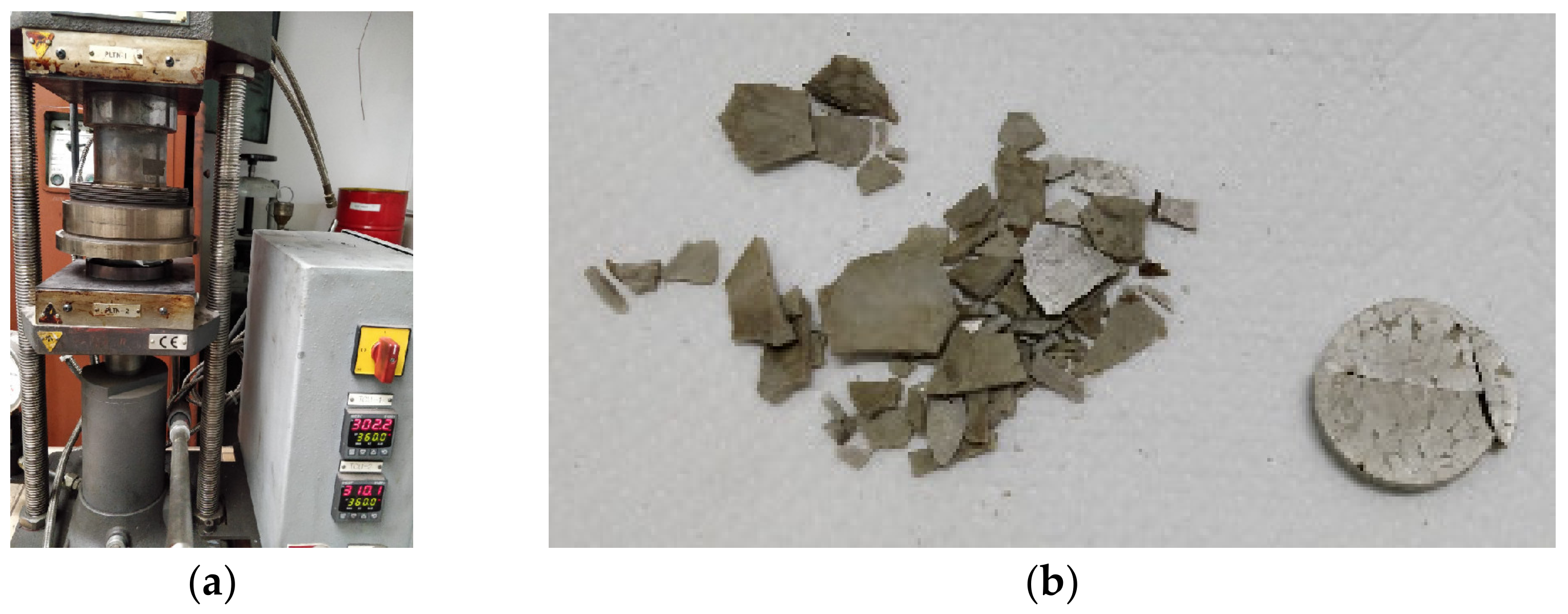
In the first phase, we attempted to obtain the materials by hot pressing with a press machine at a temperature of 310 °C.
Very friable pieces were obtained that could not be extracted whole from the mold. The press and the resulting plates are presented in Figure 2.
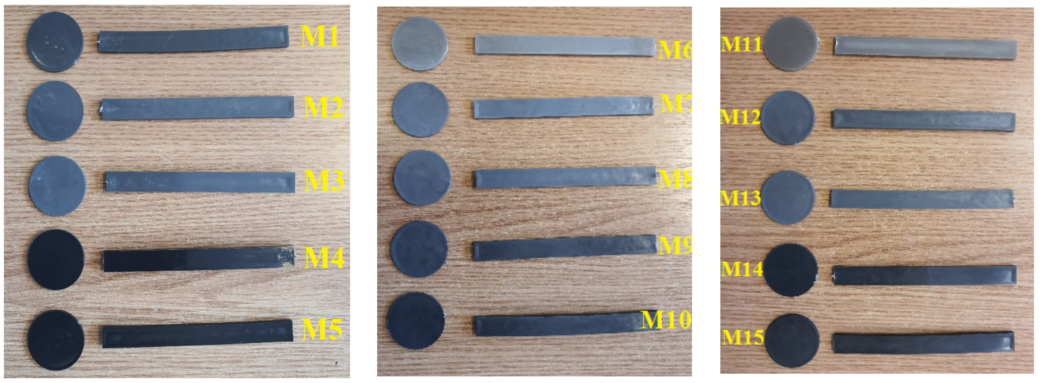
These composite materials can be classified into 3 sets:
  • 5 experimental models of composite materials using a PET polymer matrix and Al and Fe nanopowders reinforcers of 800 nm in grain size in concentrations of 5% and 8%, codified as follows:
    M1 recycled PET.
    M2 PET + 5% Al nanopowder.
    M3 PET + 8% Al nanopowder.
    M4 PET + 5% Fe nanopowder.
    M5 PET + 8% Fe nanopowder.
  • 5 experimental models of composite materials using as a polymer matrix a mixture of PET and PP polymers and Al and Fe nanopowder reinforcers of 800 nm granulation in a concentration of 5% and 8%, codified as follows:
    M6 PET 70% + PP 30%.
    M7 PET + PP + 5% Al nanopowder.
    M8 PET + PP + 8% Al nanopowder.
    M9 PET + PP + 5% Fe nanopowder.
    M10 PET + PP + 8% Fe nanopowder.
  • 5 experimental models of composite materials using as a polymer matrix a mixture of two polymers PET + HDPE (High-Density Polyethylene) and reinforcing Al and Fe nanopowders of 800 nm granulation in a concentration of 5% and 8%, coded as follows:
    M11 PET 70% + HDPE 30%.
    M12 PET + HDPE + 5% Al nanopowder.
    M13 PET + HDPE + 8% Al nanopowder.
    M14 PET + HDPE + 5% Fe nanopowder.
    M15 PET + HDPE + 8% Fe nanopowder.
The composite materials obtained from this set are shown in Figure 3, while the processing temperature regimes presented by the machine interface are presented in Table 1.
It is found that composite materials containing Al nanopowders (M2, M3, M7, M8, M12, and M13) are easy to process compared to those containing Fe nanopowders (M4, M5, M9, M10, M14, and M15) due to the fact that aluminum is a soft metal that allows easy embedding in the polymer matrix, which also induces better homogenization.
To remedy this shortcoming, it is recommended to process composite materials through the two classical stages: The extrusion that performs the mixing of the polymeric material with the reinforcer (the nanopowder) and then injection from the melt into the shapes required for the final packaging. Through these two processing stages, good homogenization is obtained, but it involves higher costs.

2.3. Characterization Methods

For the optical characterization of the samples of thermoplastic packaging received from the beneficiary, an FTIR spectrophotometer, model Vertex 80, from Bruker was used. These spectra were recorded in the totally attenuated reflection geometry (ATR). The spectra were recorded using the OPUS 6.0 acquisition program. According to the protocol, it was necessary to produce a background and then record each test sample. The parameters used were as follows: The spectral range was 600–4000 cm−1, the number of scans was 64, and the resolution was 4 cm−1. After recording each spectrum, atmospheric compensation was performed in order to eliminate the contribution of water vapor and CO2. The spectra were saved with the dpt. extension, being imported into Origin 2018.
SEM scanning optical microscopy analysis was performed with a Scanning Electron Microscope with a field emission source and focused ion beam. Images were taken at an accelerating voltage of 1 or 2 kV with very close proximity to the objective lens. The detector used was the Everhart Thornley type secondary electron detector with a Faraday cup—resulting in micrographs that highlight the morphology and topography of the analyzed surfaces. The fields recorded in these micrographs are relatively narrow, from a few hundred microns to 10–20 microns, depending on the magnification used, with the analyzed materials not showing major variations in two randomly analyzed fields.
Thermogravimetric analysis and differential calorimetry (TGA/DSC) were carried out with the help of the simultaneous thermal analyzer TGA-DSC type STA 449 F3 Jupiter, NETZSCH, Germany. The conditions of the TGA/DSC measurements performed on solid samples of composite polymer materials (5–10 mg) were as follows: A temperature range of 25–300 °C; a heating speed of 10 K/min; a working atmosphere of nitrogen; a reference substance of aluminum crucible. Before introducing the sample to be analyzed into the device, it was weighed on a digital balance type Precisa XT 220A (Switzerland), with a digital display with a precision class of 0.1 mg.

3. Results and Discussions

3.1. FTIR Measumeremts

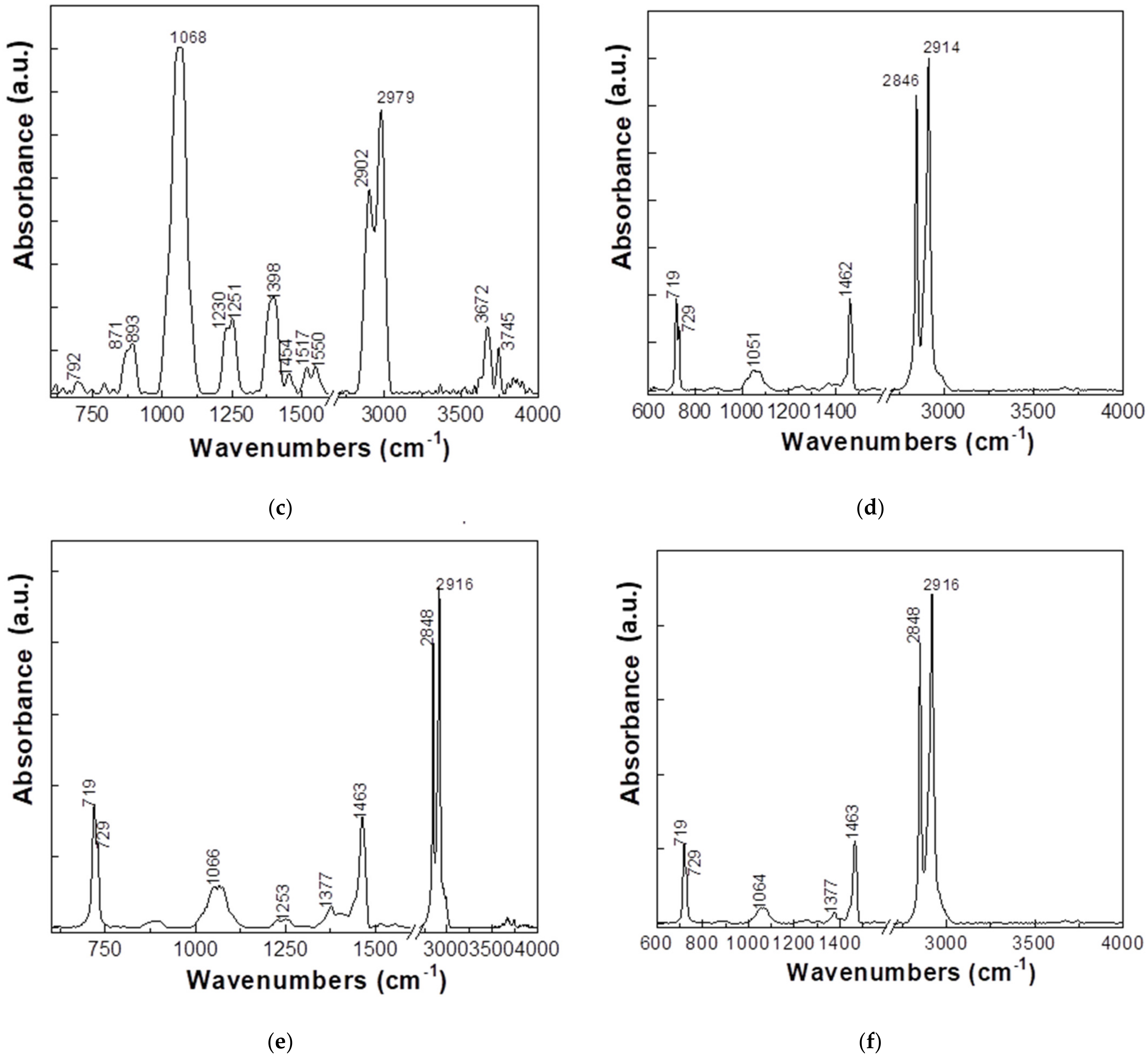
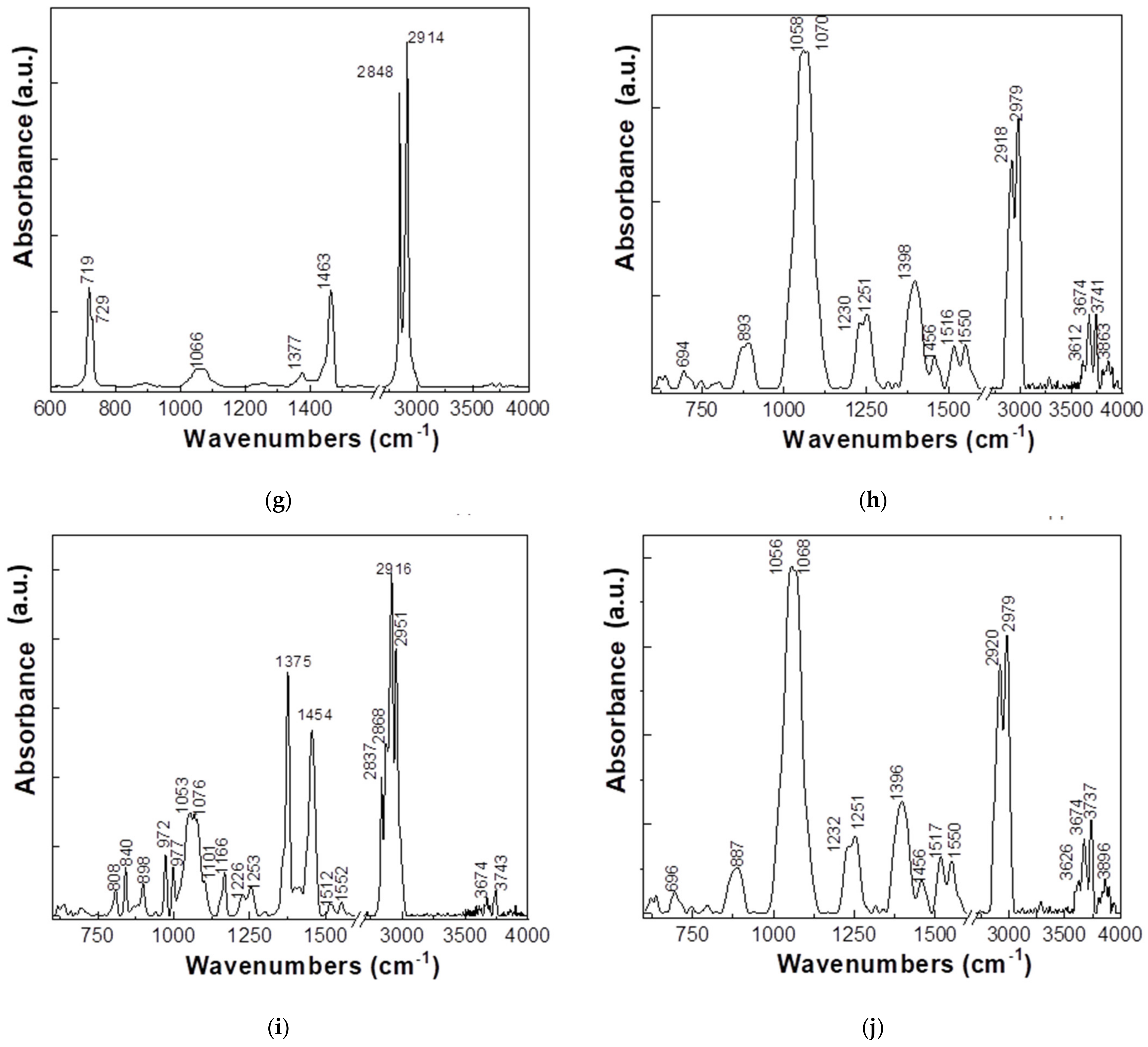
FTIR absorption spectra are illustrated in Figure 4.
The analysis of the FTIR spectra presented in Figure 4 shows the case of the labeled sample as follows:
(a)
HDPE + 8% Fe, 50 nm, has two IR bands with higher absorbance at approximately 1066 and 2900–2979 cm−1 being accompanied by other IR bands with lower absorbance having maxima at 879, 1251, 1400, 1454, 1515–1550, and 3678 cm−1.
(b)
HDPE + 8% Al, 50 nm, presents the following IR bands with maxima at 717, 729, 1053, 1462, 2846, and 2914 cm−1.
(c)
HDPE + 5% Al, 800 nm, shows two intense bands at 1068 and 2902–2979 cm−1, being accompanied by other IR bands with lower absorbance at approximately 871–893, 1230–1251, 1398, 1454, 1517–1550, and 3672–3745 cm−1.
(d)
HDPE + 3% Ferrite presents the following IR bands with maxima at approximately 719–729, 1051, 1462, and 2846–2914 cm−1.
(e)
LDPE + 5% Fe, 50 µm, presents IR bands with maxima at approximately 719–729, 1066, 1463, and 2848–2916 cm−1.
(f)
LDPE + 5% Ferrite, the position of the main IR bands is approximately 719–729, 1064, 1463, and 2848–2916 cm−1.
(g)
LDPE + 8% Al, presents IR bands with maxima at approximately 719–729, 1066, 1463, and 2848–2914 cm−1.
(h)
PP + 8% Ferrite, presents IR bands with maxima at approximately 893, 1058–1070, 1230–1251, 1398, 1454, 1516–1550, 2918–2979, and 3612–3674–3741 cm−1.
(i)
PP + 8% Fe, 800 nm, shows IR bands with maxima at approximately 808, 840, 898, 977, 1101, 1053–1076, 1166, 1226–1253, 1375, 1454, 2837–2868–2916–2951, and 3674–3743 cm−1.
(j)
PP + 8% Al, 50 nm, presents IR bands with maxima at 887, 1056–1068, 1232–1251, 1396, 1454, 1517–1550, 2920–2979, and 3626–3674–3737 cm−1.
HDPE + 8% Al, 50 nm, HDPE + 3% Ferrite, LDPE + 5% Fe, 50 µm, LDPE + 5% Ferrite, and LDPE + 8% Al samples show IR bands that are located in the vicinity of those reported in the case of polyethylene at approximately 720–731, 1463, 2851, and 2919 cm−1; they were attributed to the vibrational modes of tilting deformation, bond deformation, symmetric stretching of the CH2 bond, and asymmetric stretching of the CH2 bond, respectively [36].
The sample PP + 8% Fe, 800 nm shows IR bands whose maxima are in the vicinity of those located at approximately 992, 997, 1375, 1452, 2839, 2872, 2916, and 2953 cm−1. They were assigned as follows: The first two vibrational modes related to the isotactic entities of the macromolecular chains and the bond and stretching vibrational modes of the methylene group, respectively [37,38,39].

3.2. DSC Measurements

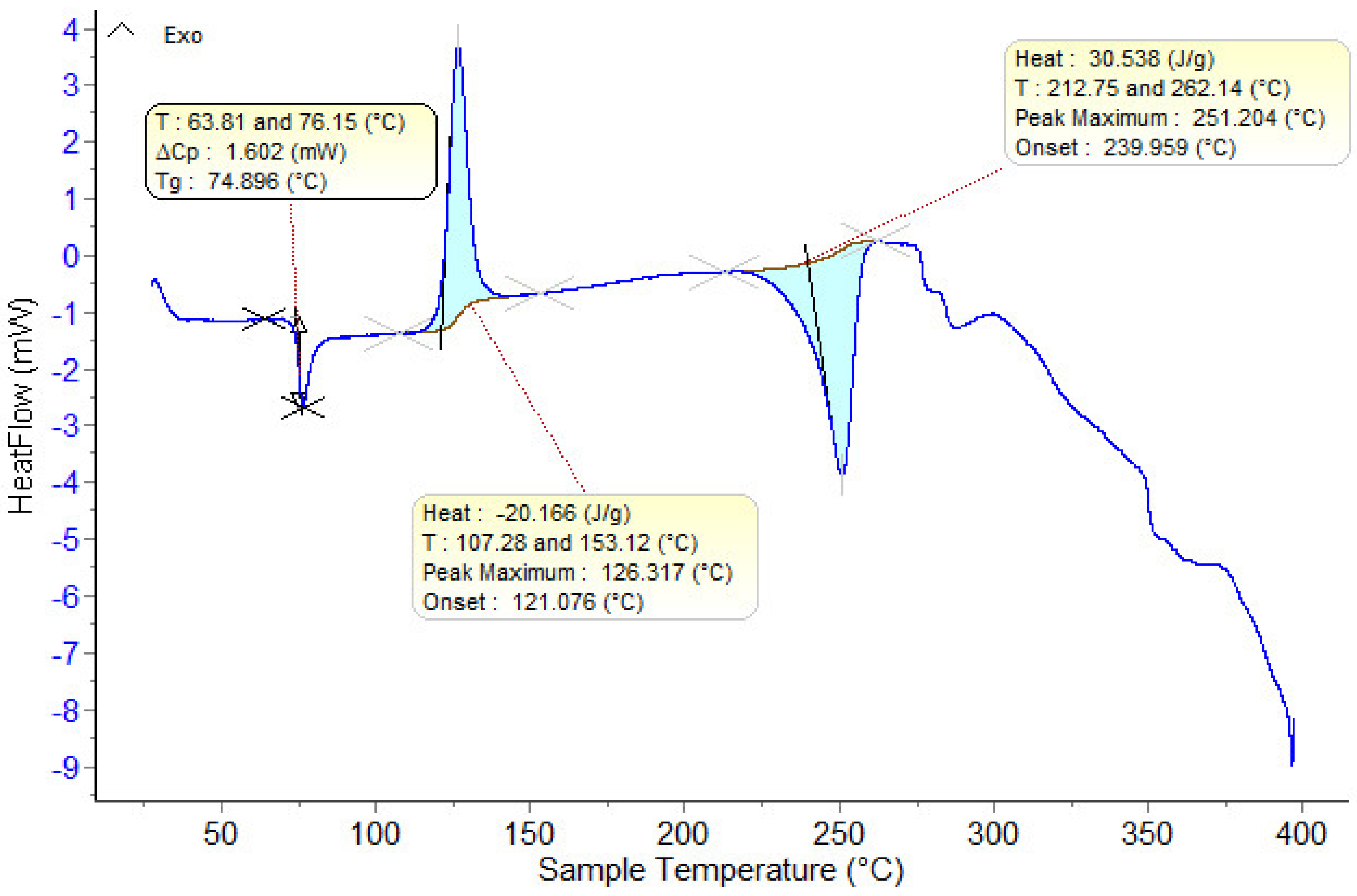
In Figure 5, the DSC curve for the initial (undried) PET is shown.
The material presents the following thermal effects: A glass transition temperature (Tg) at approximately 75 °C; a thermal crystallization temperature at approximately 126 °C; a melting temperature at approximately 251 °C.
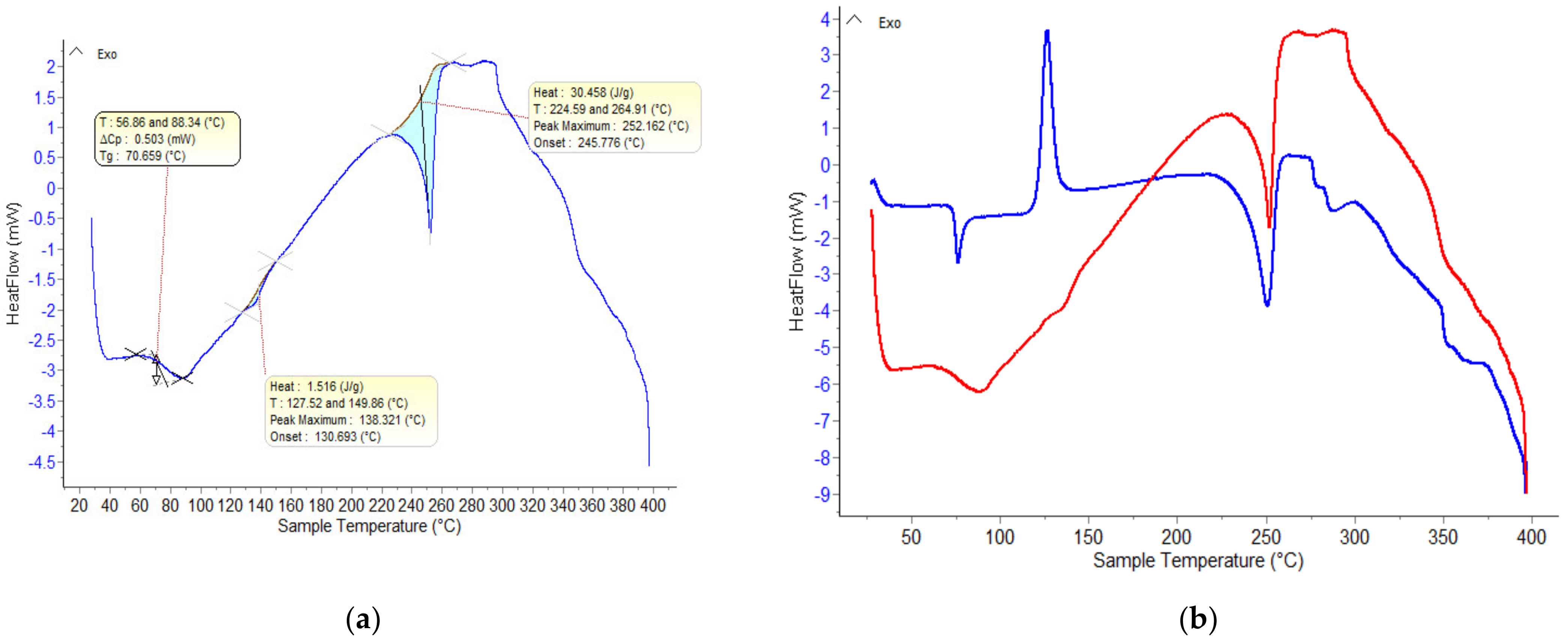
From Figure 6, the thermally treated material shows the following thermal effects: A glass transition temperature (Tg) at approximately 70 °C and thermal crystallization temperature is absent. This is caused by heating the material above Tg, followed by its slow cooling. The material becomes opaque due to the spherulitic structure formed by the thermally induced crystalline aggregates of the non-oriented PET chains. Rapid cooling of the sample would have led to obtaining a material with a high degree of amorphousness, which subsequently, upon reheating, would have presented the phenomenon of thermal crystallization noticed in Figure 6 with a melting temperature of approximately 252 °C.
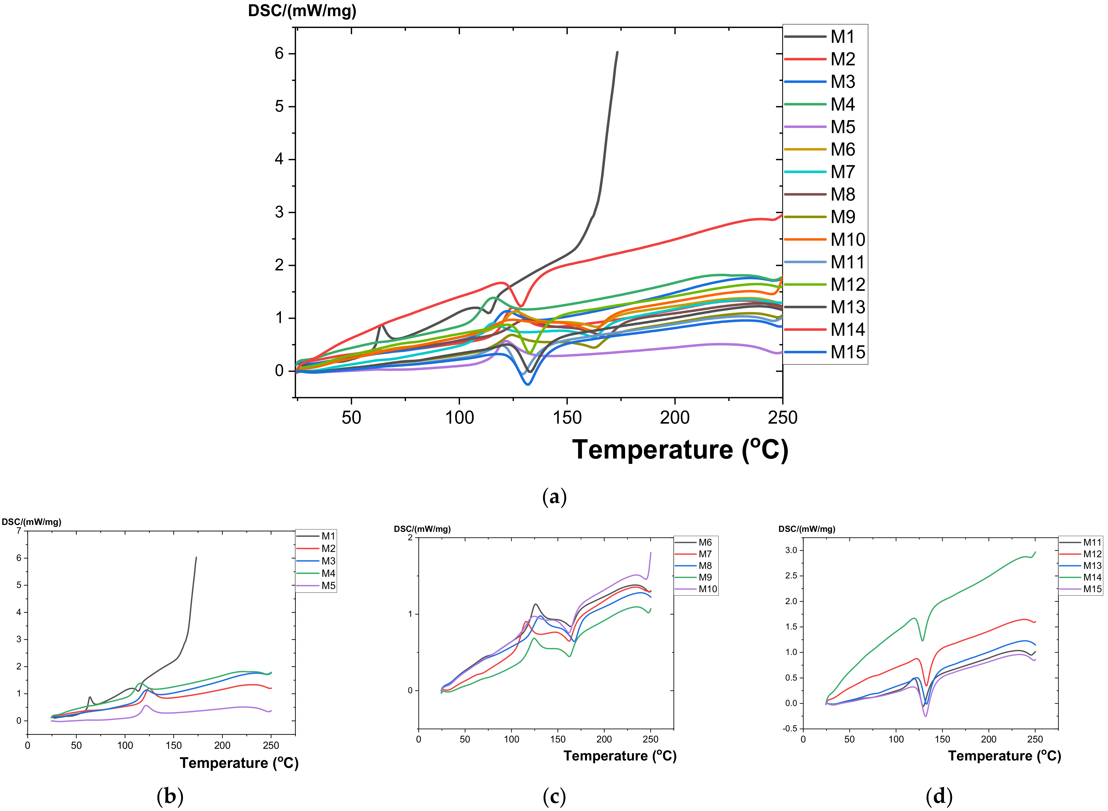
Figure 7 illustrates the analyses of the DSC variation curves as a function of temperature (25–300 °C) presented for all studied composite materials (M1–M15).
The composite materials were obtained by injection from the melt on the injection machine Dr. Boy, Germany. Thus, the experimental models are presented in Table 2.
In Table 2, the resulting values from the transformation processes (glass transition, crystallization, and melting) are presented, which were obtained from the analysis of the DSC variation curves as a function of temperature.
The composite materials thermally analyzed with the TGA/DSC analyzer consisted of a basic matrix of polyethylene terephthalate (recycled PET—M1) to which the following were added (Table 3): Reinforcement elements consisting of nanometric metal powders (800 nm) of Al (M2, M3); reinforcing elements consisting of nanometric metal powders (800 nm) of Fe (M4, M5); polypropylene Tipplen H 318-PP) (M6); polypropylene Tipplen H 318–PP and nanometric metal powders (800 nm) from Al (M7, M8); polypropylene Tipplen H 318–PP and nanometric metal powders (800 nm) from Fe (M9, M10); high-density polyethylene Tipelin—HDPE (M11); Tipelin high-density polyethylene—HDPE and nanometric metal powders (800 nm) from Al (M12, M13); Tipelin high-density polyethylene—HDPE and nanometric metal powders (800 nm) from Fe (M14, M15).
Following thermal analysis, it was found that all the studied composite materials (M1 … M15) had no mass loss transformations, which means that these materials can be used at up to 300 °C. All studied polymeric materials (M1 … M15) underwent a glass transition process (second-order phase transition) when the rubbery state changed to the glassy solid state. That happens with a transformation start temperature in the range of 63 … 74 °C and a variation of ΔCp in the range of 0.001 … 0.076 J/gK. This process occurs due to the presence of amorphous areas in the analyzed samples.
Both for the polymer material made of polyethylene terephthalate (recycled PET—M1) and the polymer composite materials with a matrix of polyethylene terephthalate (recycled PET), to which reinforcement elements consisting of nanometric metal powders (800 nm) of Al (M2, M3) or Fe (M4, M5) were added, the existence of three thermal processes was found: Glass transition, crystallization, and melting (Figure 7).
Both for the composite polymer material made of polyethylene terephthalate (recycled PET—M1) and polypropylene Tipplen H 318-PP) (M6), as well as for the polymer composite materials with a matrix of polyethylene terephthalate and polypropylene Tipplen H 318, to which elements of reinforcement consisting of nanometric metal powders (800 nm) of Al (M7, M8) or Fe (M9, M10) were added, the existence of a glass transition thermal process, a thermal crystallization process, and two melting processes was found.
For the composite polymer material made of polyethylene terephthalate (recycled PET—M1) and Tipelin high-density polyethylene—HDPE (M11), as well as for the polymer composite materials with a matrix of polyethylene terephthalate and Tipelin high-density polyethylene, to which reinforcing elements consisting of nanometric metallic powders (800 nm) of Al (M12, M13) or Fe (M14, M15) were added, the existence of a glass transition thermal process and two melting processes was found.

3.3. Measurements of Hydrostatic Density

The hydrostatic density is determined with the Metler Toledo Analytical Balance, which has the following characteristics: A maximum capacity of 220 g; precision of 0.1 mg; linearity of ±0.2 mg; internal calibration; density kit for solids and liquids; and interface RS 232.
The maximum resolution of hydrostatic density measurements in ethanol at 20 °C is 0.0005 g/cm3 (Table 4). The measurements were performed at 21 °C with three consecutive repetitions and the error was calculated. The density was determined as the mean value between three consecutive repeated measurements.
From the experimental results obtained for the hydrostatic density, it can be seen that the values are close, a fact justified by the majority content in the polymer (the polymer concentrations used were 100%, 95%, and 92%, respectively).
The composite material M10 has the highest density and M6 has the lowest compared to the other composite materials obtained.
The swelling capacity of polymers is determined by the amount of liquid that the material can absorb when immersed in a liquid. In the case of this report, water was chosen as the liquid swelling medium as a universal solvent for packaging.

3.4. Measurements of Swelling Capacity

To determine the swelling capacity in water for the composite materials studied, the procedure was carried out according to SR EN ISO 175/2011 [40]: approximately 0.085 g of composite material was weighed on average and placed in plastic ampoules with tight caps (tubes for micro-Centrifuges with a diameter of 10 mm and a length of 40 mm); vials with composite material, thus made, were filled with deionized water and maintained for 72 h at a temperature of 22 °C (atmospheric) and a humidity of 41%.
To determine the degree of swelling, Formula (1) was used:
Q = X 2 X 1 X 1 × 100
where:
  • Q—degree of swelling.
  • X2,3,4,…—mass of swollen polymer (after each 168-h cycle).
  • X1—dry polymer mass.
An analytical balance was used to determine the mass variation (Table 5).
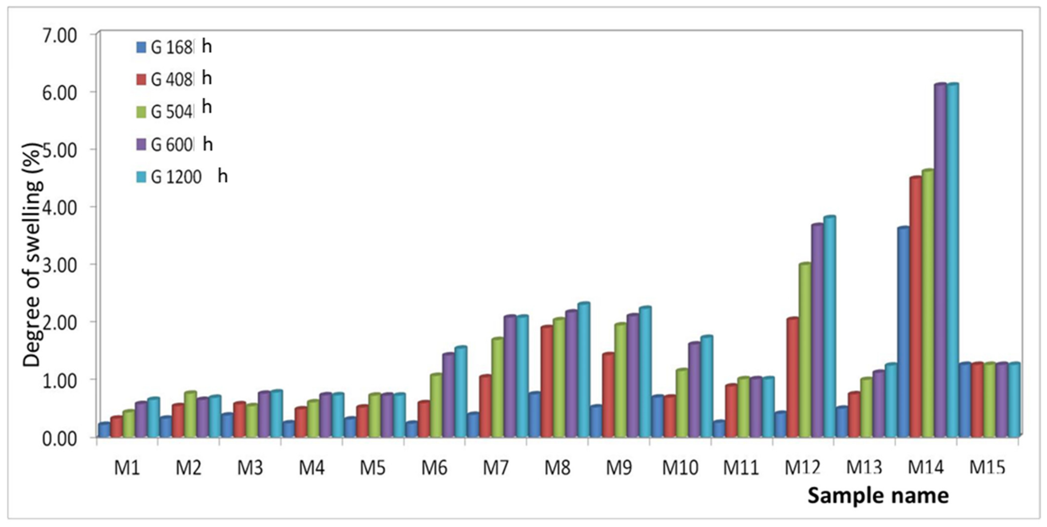
The swelling times in water were 168, 408, 504, 600, and 1200 h (Figure 8).
From the experimental results, the following classification of the composite materials studied can be made from the point of view of the increase in the degree of swelling in water depending on the exposure time.
After 168 h for polymer matrix materials from:
-
PET (M1–M5): It is found that the highest water absorption is presented by M3 and the lowest by M1. This can be justified by the fact that the percentage of 8% Al nanopowder creates the most voids in the mixing process in the melt, which creates the possibility of inserting water. The values of the degree of swelling are very close due to the majority concentration of the polymer. The classification of materials is as follows: Q M1 < Q M4 < Q M5 < Q M2 < Q M3;
-
PET + PP (M6–M10): It is found that M8 has the highest water absorption and M1 has the lowest. Here it can be seen that the Al nanopowder creates more voids than the Fe one. The classification of materials is as follows: Q M6 < Q M7 < Q M9 < Q M10 < Q M8;
-
PET + HDPE (M11–M15): It is found that M14 has the highest water absorption and M11 has the lowest. In this case, it is observed that the materials containing Al nanopowder have a lower degree of swelling than those with Fe nanopowder. It can be said that in the PET + HDPE polymer mixture, Al nanopowder is better homogenized than Fe. The classification of materials is as follows: Q M11 < Q M12 < Q M13 < Q M15 < Q M14;
After 408, 504, 600, and 1200 h, it was found that the direction of the increase in the degree of swelling is the same as after 168 h.
It can be said that the studied materials are resistant to the action of water. The most hygroscopic material among those analyzed is M14.

3.5. SEM Measurements

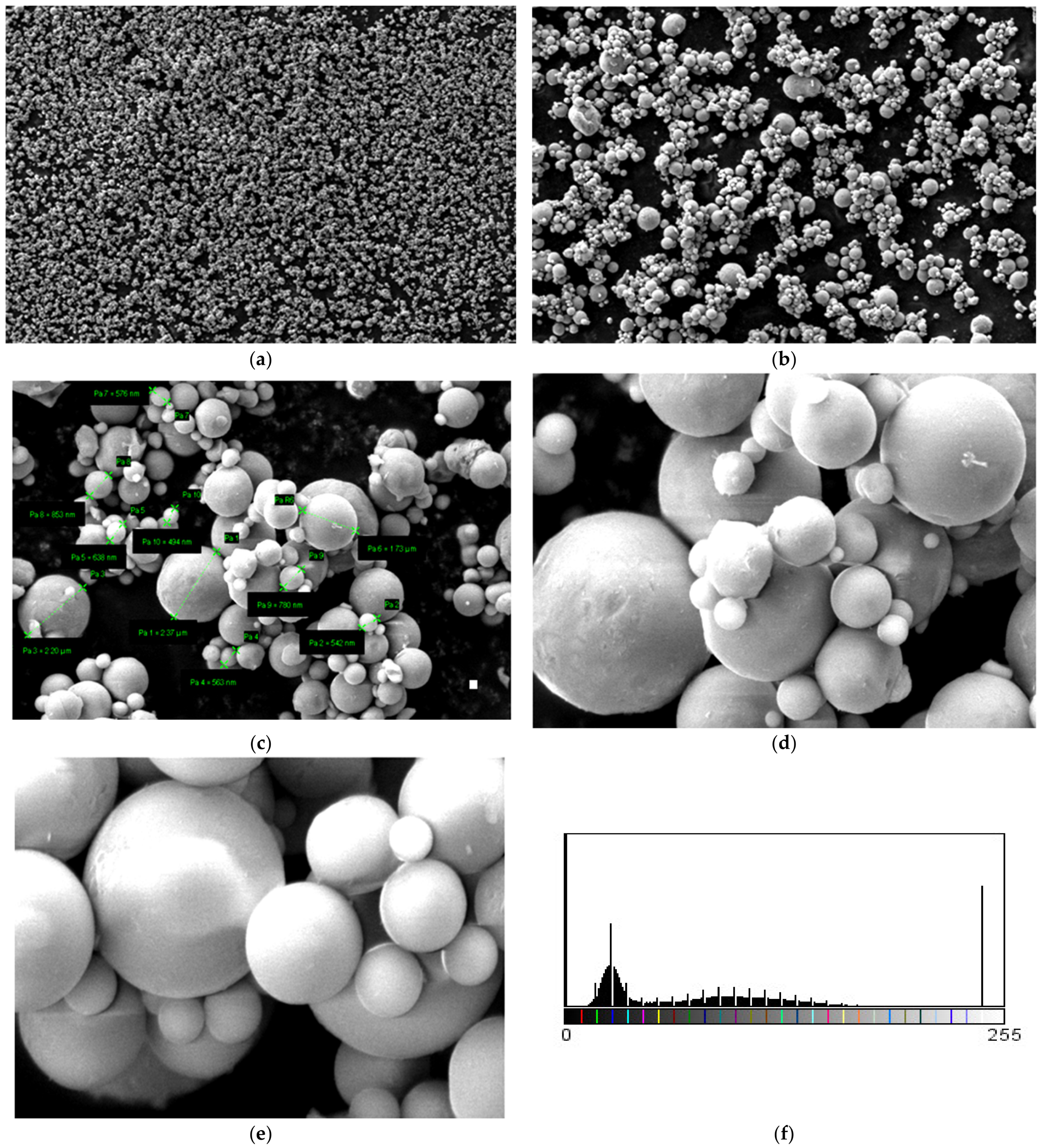
Micrographs were made for Al powder and are shown in Figure 9. A large dispersion of particle sizes is observed from the micrographs. To highlight this, 10 measurements of Al 800 nm powder particles were made, and the following values were observed: 2.37 μm, 542 nm, 638 nm, 1.73 μm, 576 nm, 853 nm, 780 nm, and 494 nm. It can be said that this nanopowder has smooth spherical particles and an average size of 798 nm.
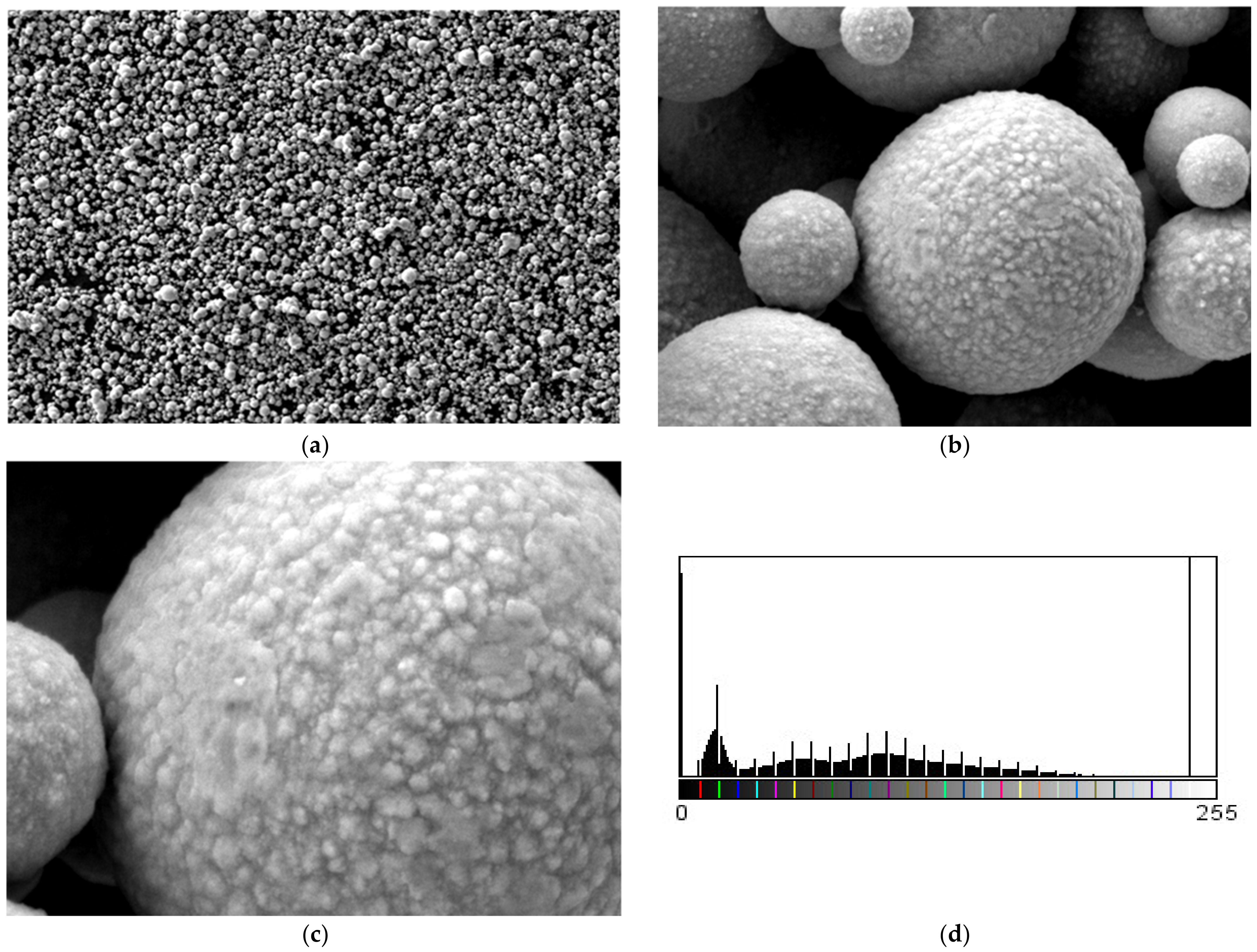
For the 800 nm Fe nanopowder, micrographs are shown in Figure 10. A large dispersion of particle sizes is found. The evidence of the differences in the granulation of the Fe 800 nm powder is presented as the results of six measurements of the powder particles and the following values were observed: 7.25 µm, 2.9 µm, 3.01 µm, 1.01 µm, 769 nm, and 1.23 µm. It can be said that this nanopowder has rough spherical particles with an average size of 2.78 µm.
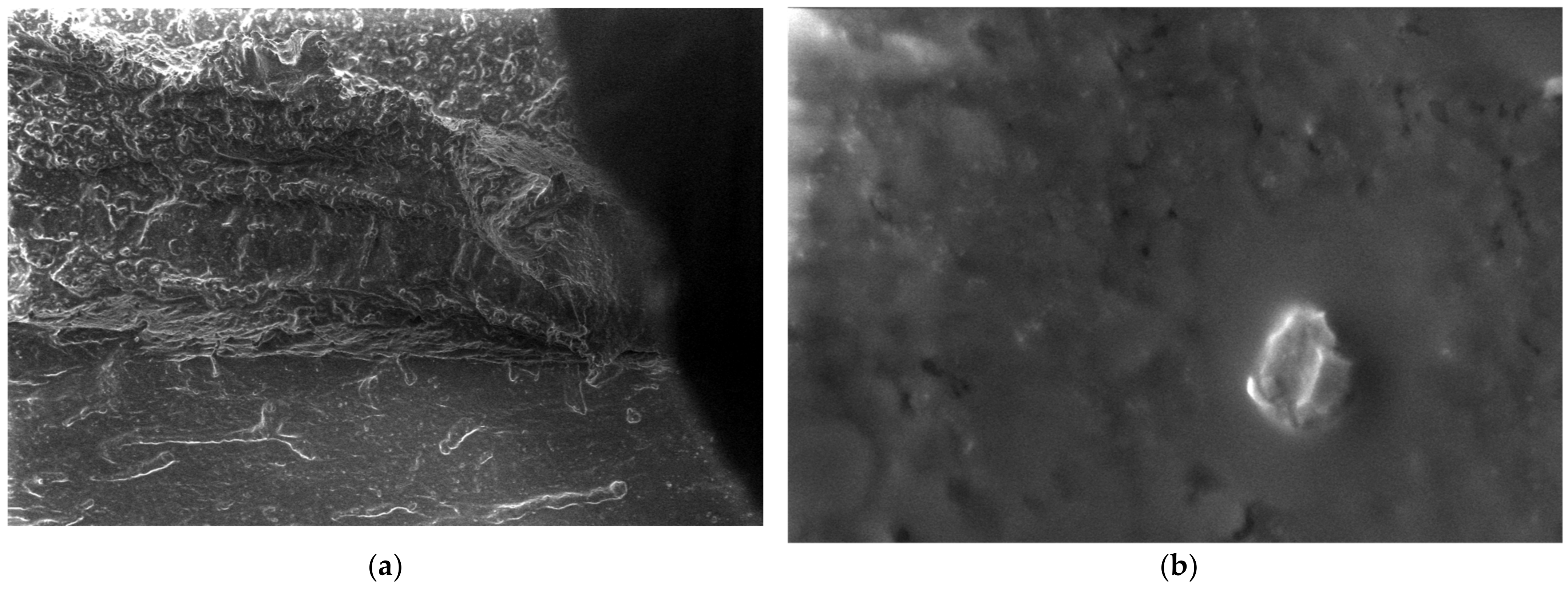
In the case of polypropylene (PP), which is a natural polymer, the structure of the polymer and the melting process can be observed from the micrographs. For this material, micrographs were formulated. These images are presented in Figure 11.
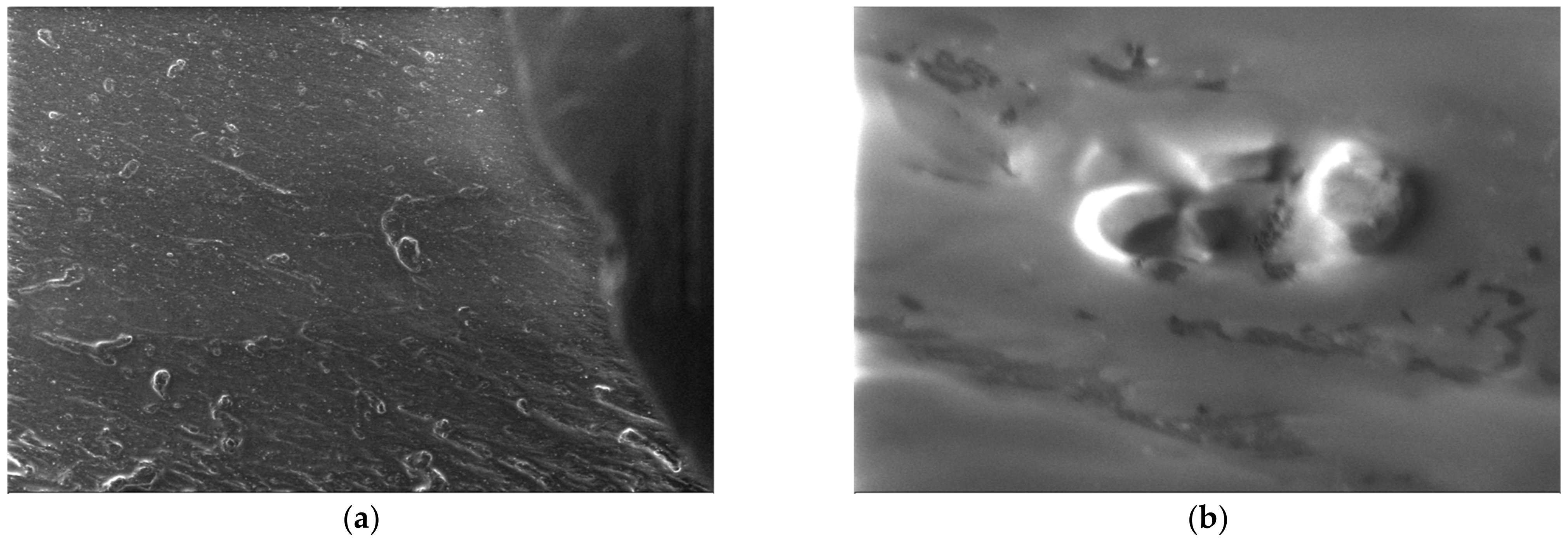
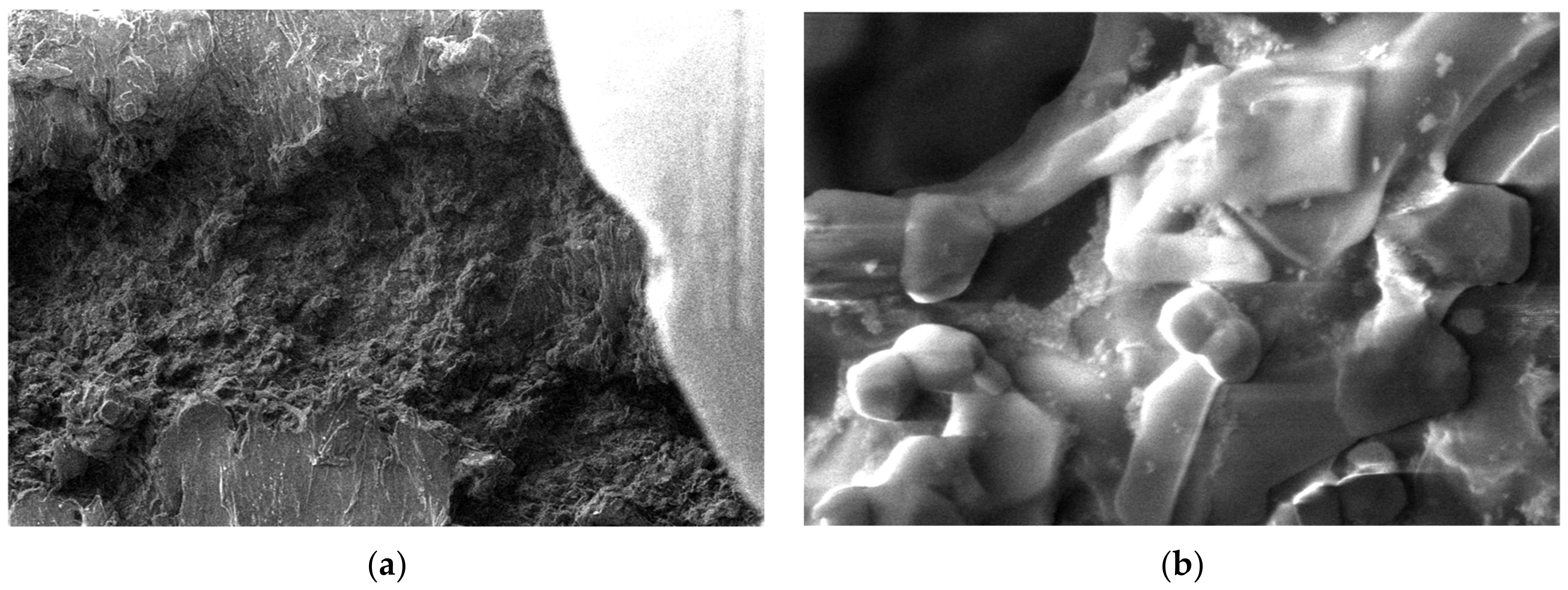
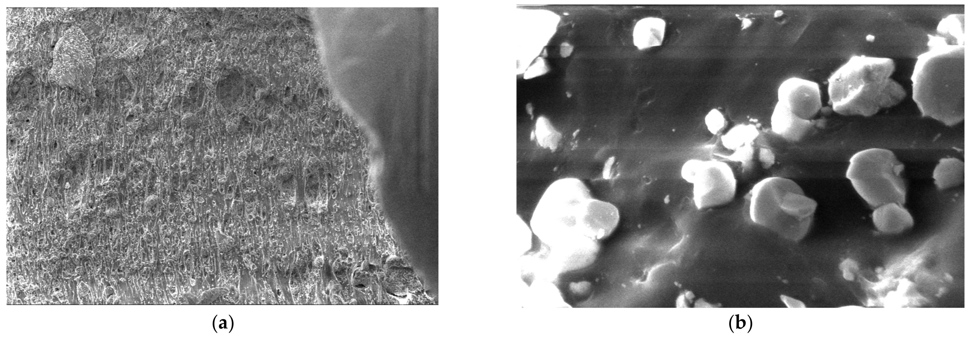
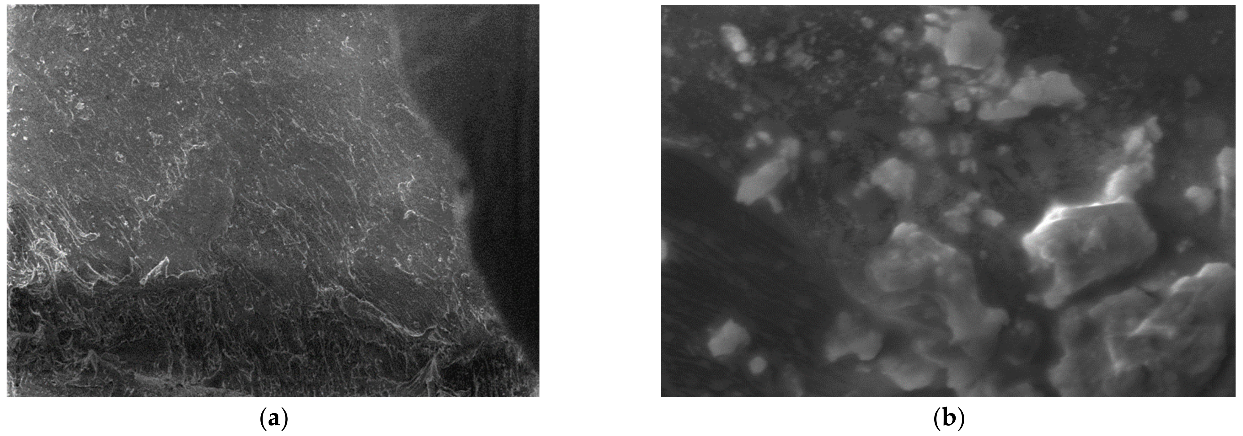
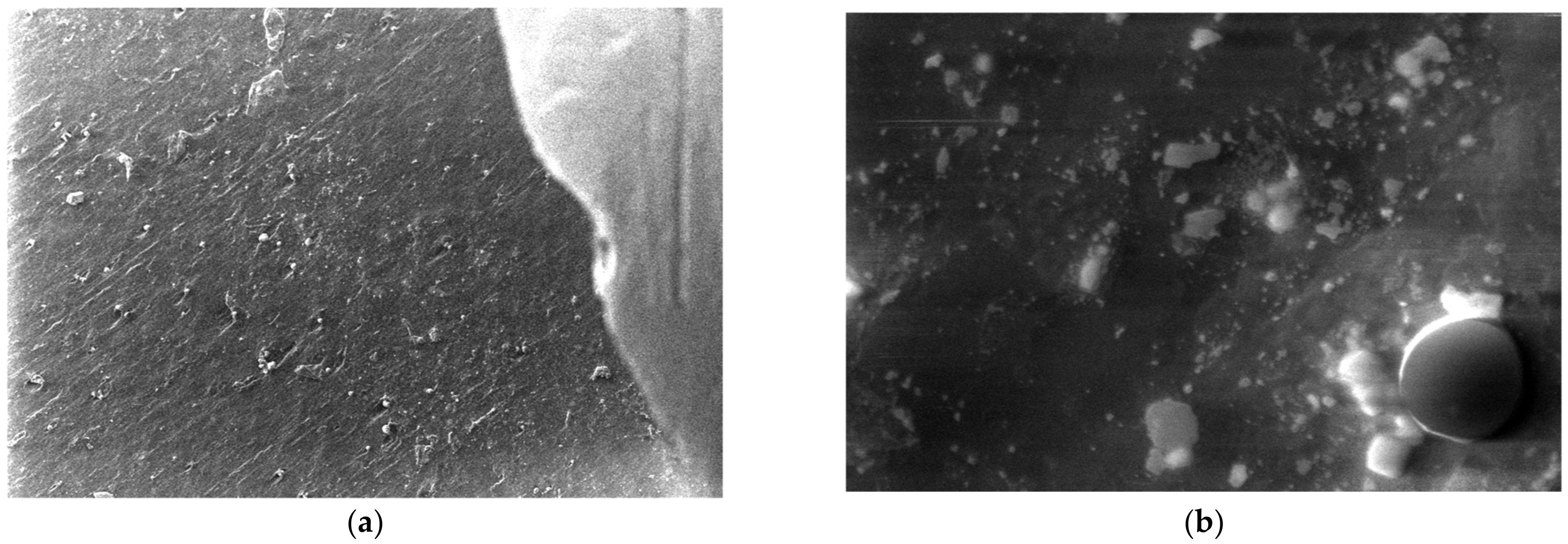
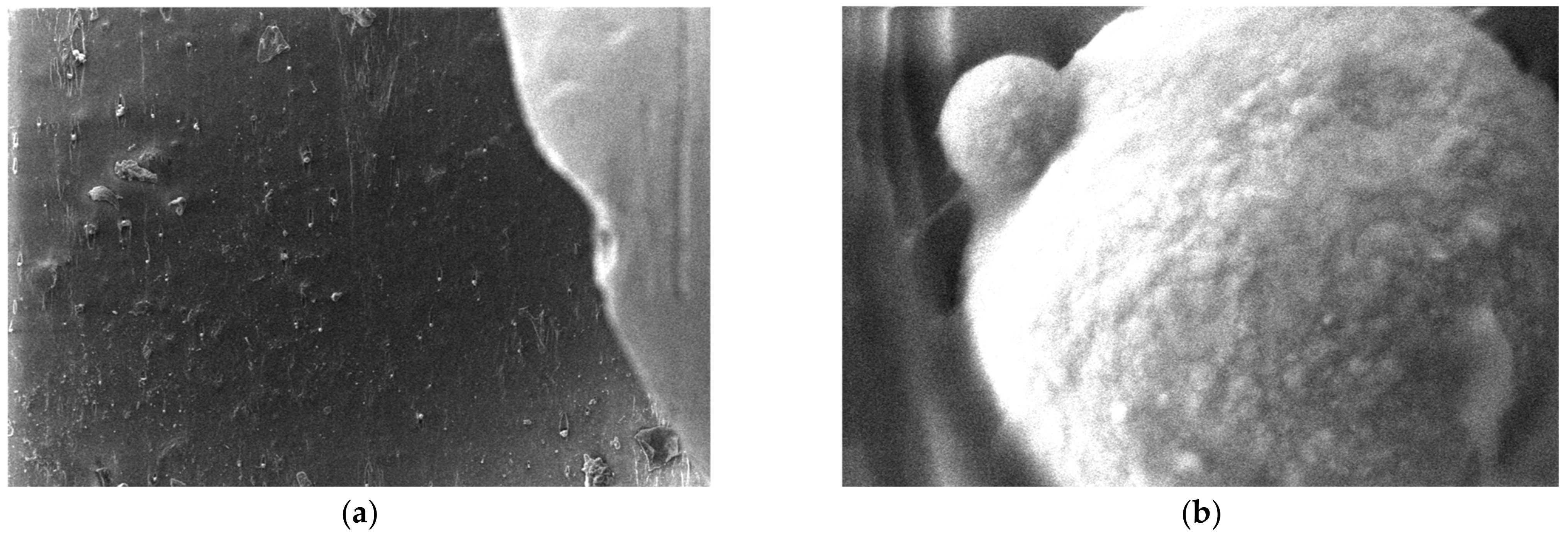
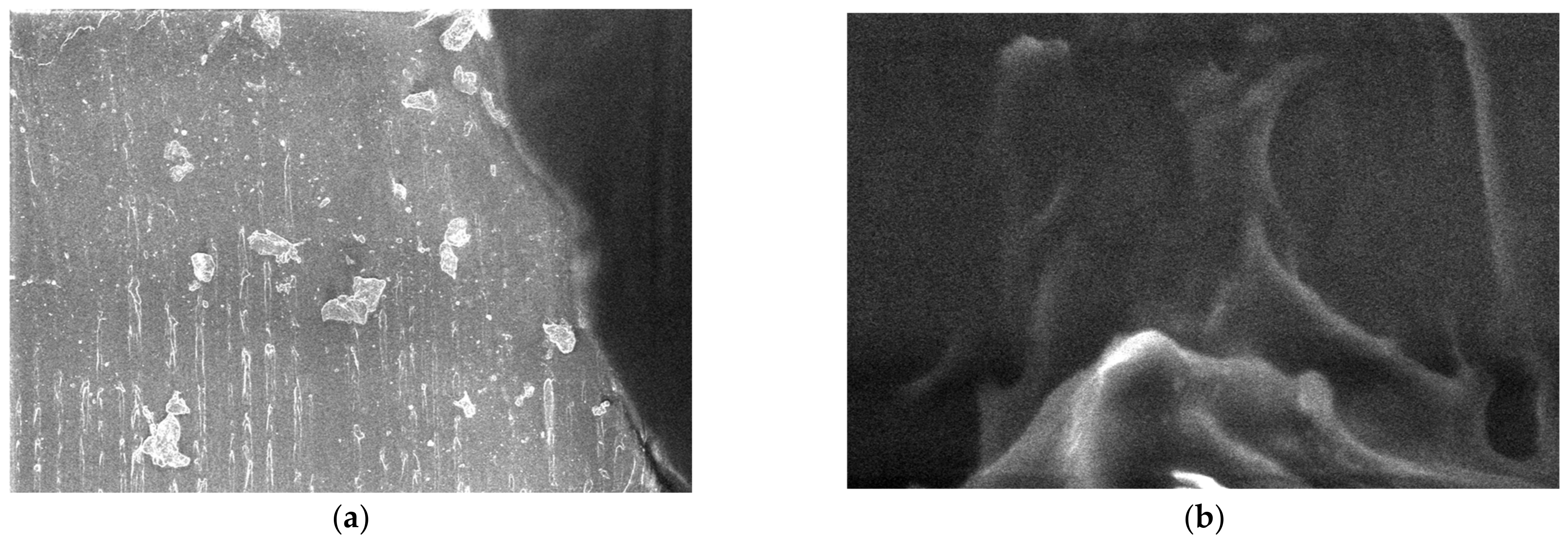
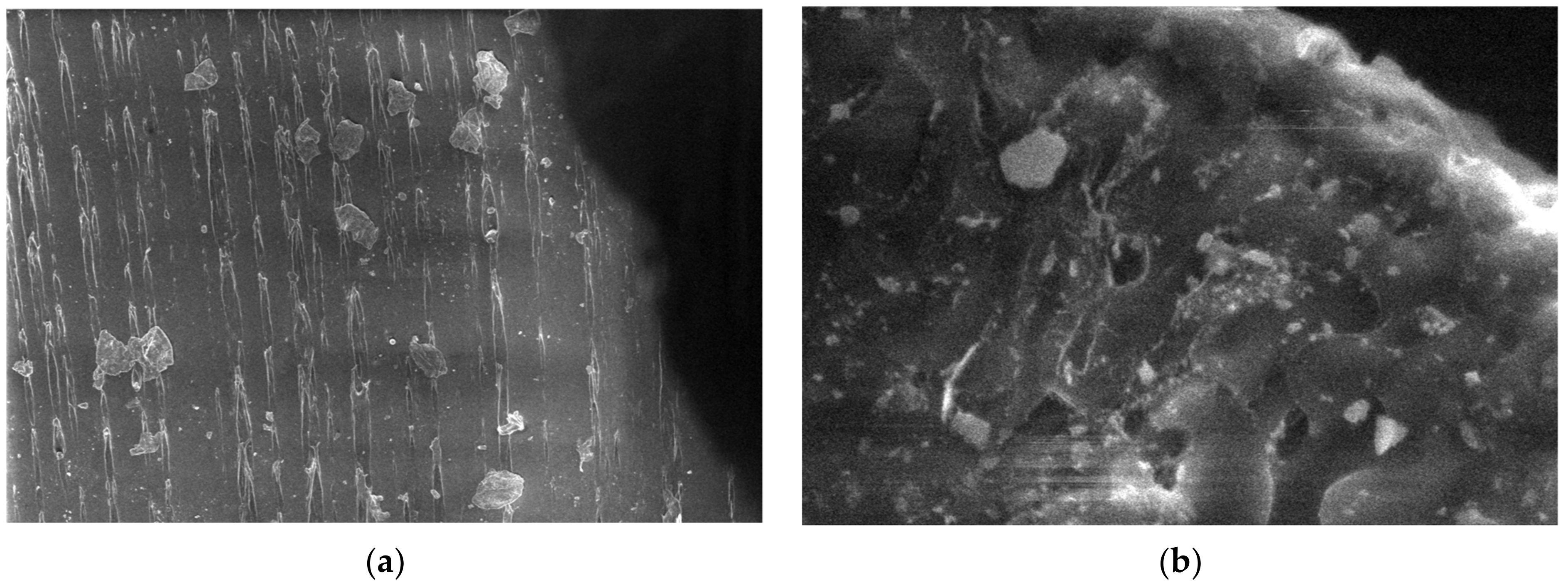
For the obtained composite materials, micrographs were made at magnifications of 500 and 50,000 as shown in Figure 12, Figure 13, Figure 14, Figure 15, Figure 16, Figure 17, Figure 18, Figure 19, Figure 20, Figure 21, Figure 22 and Figure 23.
From the micrographs produced on the obtained composite materials, it can be said that:
-
It can be observed from the composition that for M7 and M8, the smooth powder particles are specific to aluminum, and for M8 and M10, the rough spherical particles are specific to iron.
-
Among these experimental models, it is found that the most homogeneous is M7 (the agglomerations are less), making it optimal for the production of special packaging to be used in the food and pharmaceutical industries.

4. Conclusions

The development of novel metallic-based nanocomposites containing metal-loaded inorganic materials or metal nanoparticles is providing advanced properties for tailored applications, which are being explored in food packaging. Although they typically enhance membrane function, metallic nanoparticles have the potential to alter or even degrade membrane performance.
To identify the best kinds and compositions of nanoparticles to include in polymeric membranes, considerable research must be performed. In this study, FTIR, SEM, and DSC methods were chosen to study the pristine and composite materials. The composite material PET + PP + 8% Fe nanopowder has the highest density and PET 70% + PP 30% has the lowest compared to the other composite materials obtained. The polymer composites containing Al nanopowder have smooth, spherical particles, whereas the ones containing Fe have rough, spherical bigger particles, as determined by SEM measurements. The studied materials are resistant to the action of water. The most hygroscopic material among those analyzed is PET + HDPE +5% Fe nanopowder.
However, laws must take into account possible dangers related to nano-dimensions and the probable migration of metal ions into foods and beverages prior to commercial application.

Author Contributions

Conceptualization, R.C.C. and M.A. (Magdalena Aflori); methodology, C.M.S., V.T. and A.R.C.; validation, I.I., V.M. and E.G.H.; writing—original draft preparation, R.C.C. and M.A. (Mihaela Aradoaei); writing—review and editing, R.C.C. and M.A. (Magdalena Aflori). All authors have read and agreed to the published version of the manuscript.

Funding

This research was funded by NANO-REV-EM-ASAM Project/Competitiveness Operational Programme 2014–2020, under grant ID P_37_757, cod my SMIS: 104089, nr. 119/16.09.2016 and by the Ministry of Research, Innovation and Digitization through contract PN23140201/42N-2023.

Conflicts of Interest

The authors declare no conflict of interest.

References

  1. European Commission. A European Strategy for Plastics in a Circular Economy. Communication from the Commission to the European Parliament, the Council, the European Economic and Social Committee and the Committee of the Regions. European Commission: Brussels, Belgium, 2018. Available online: https://eur-lex.europa.eu/legal-content/EN/TXT/?uri=COM%3A2018%3A28%3AFIN (accessed on 16 January 2018).
  2. European Commission. Report from the Commission to the European Parliament, the Council, the European Economic and Social Committee and the Committee of the Regions on the Implementation of the Circular Economy Action Plan. Available online: https://eur-lex.europa.eu/legal-content/EN/TXT/?uri=CELEX%3A52019DC0190 (accessed on 2 June 2023).
  3. Matthews, C.; Moran, F.; Jaiswal, A.K. A review on European Union’s strategy for plastics in a circular economy and its impact on food safety. J. Clean. Prod. 2021, 283, 125263. [Google Scholar] [CrossRef]
  4. IK Industrievereinigung Kunststoffverpackungen e.V.; Plastics Europe Deutschland e.V. The Plastic Packaging Industry’s Path to a Circular Economy. Available online: https://newsroom.kunststoffverpackungen.de/en/2020/06/18/the-plastic-packaging-industrys-path-to-a-circular-economy/ (accessed on 25 June 2023).
  5. Plastics Europe. Plastics—The Facts 2015 an Analysis of European Plastics Production, Demand and Waste Data. 2015. Available online: http://www.plasticseurope.org/download_file/view/479/179 (accessed on 25 June 2023).
  6. Kamble, A.; Tanwar, S.; Shanbhag, T. Isolation of plastic degrading micro-organisms from soil samples collected at various locations in Mumbai, India. Int. Res. J. Environment Sci. 2015, 4, 77–85. [Google Scholar]
  7. Harrison, J.P.; Schratzberger, M.; Sapp, M.; Osborn, A.M. Rapid bacterial colonization of low-density polyethylene microplastics in coastal sediment microcosms. BMC Microbiol. 2014, 14, 232. [Google Scholar] [CrossRef] [PubMed] [Green Version]
  8. Driedger, A.G.J.; Dürr, H.H.; Mitchell, K.; Van Cappellen, P. Plastic debris in the Laurentian Great Lakes: A review. J. Great Lakes Res. 2015, 41, 9–19. [Google Scholar] [CrossRef]
  9. Al-Sabagh, A.M.; Yehia, F.Z.; Eshaq, G.; Rabie, A.M.; ElMetwally, A.E. Greener routes for recycling of polyethylene terephthalate. Egypt. J. Pet. 2016, 25, 53–64. [Google Scholar] [CrossRef] [Green Version]
  10. Harper, C.A. Modern Plastics Handbook, 1st ed.; McGraw Hill: New York, NY, USA, 1999. [Google Scholar]
  11. Tokiwa, Y.; Calabia, B.P.; Ugwu, C.U.; Aiba, S. Biodegradability of plastics. Int. J. Mol. Sci. 2009, 10, 3722–3742. [Google Scholar] [CrossRef] [Green Version]
  12. Sepperumal, U.; Markandan, M.; Palraja, I. Micromorphological and chemical changes during biodegradation of Polyethylene terephthalate (PET) by Penicillium sp. J. Microbiol. Biotechnol. 2013, 3, 47–53. [Google Scholar]
  13. Koshti, R.; Mehta, L.; Samarth, N. Biological Recycling of Polyethylene Terephthalate: A Mini-Review. J. Polym. Environ. 2018, 26, 3520–3529. [Google Scholar] [CrossRef]
  14. Munoz, M.; Ortiz, D.; Nieto-Sandoval, J.; de Pedro, Z.M.; Casas, J.A. Adsorption of micropollutants onto realistic microplastics: Role of microplastic nature, size, age, and NOM fouling. Chemosphere 2021, 283, 131085. [Google Scholar] [CrossRef]
  15. Aflori, M.; Drobota, M. Combined treatments for the improving of the PET surfaces hydrophilicity. Dig. J. Nanomat. Biostruct. 2015, 10, 587–593. [Google Scholar]
  16. Gebre, S.H.; Sendeku, M.G.; Bahri, M. Recent Trends in the Pyrolysis of Non-Degradable Waste Plastics. ChemistryOpen 2021, 10, 1202–1226. [Google Scholar] [CrossRef] [PubMed]
  17. Geyer, R.; Jambeck, J.; Lavender Law, K. Production, use, and fate of all plastics ever made. Sci. Adv. 2017, 3, e1700782. [Google Scholar] [CrossRef] [PubMed] [Green Version]
  18. D’Ambrieres, W. Plastics recycling worldwide: Current overview and desirable changes. Field Actions Sci. Rep. 2019, 19, 12–21. [Google Scholar]
  19. Barthelemy, E.; Spyropoulos, D.; Milana, M.R.; Pfaff, K.; Gontard, N.; Lampi, E.; Castle, L. Safety evaluation of mechanical recycling processes used to produce polyethylene terephthalate (PET) intended for food contact applications. Food Addit. Contam. 2014, 31, 490–497. [Google Scholar] [CrossRef]
  20. Dodi, G.; Popescu, D.; Cojocaru, F.D.; Aradoaei, M.; Ciobanu, R.C.; Mihai, C.T. Use of Fourier-Transform Infrared Spectroscopy for DNA Identification on Recycled PET Composite Substrate. Appl. Sci. 2022, 12, 4371. [Google Scholar] [CrossRef]
  21. Raheem, A.B.; Noor, Z.Z.; Hassan, A.; Hamid, M.K.A.; Samsudin, S.A.; Sabeen, A.H. Current developments in chemical recycling of post-consumer polyethylene terephthalate wastes for new materials production: A review. J. Clean. Prod. 2019, 225, 1052–1064. [Google Scholar] [CrossRef]
  22. Mancini, S.D.; Schwartzman, J.A.S.; Rodriques Nogueira, A.; Kagohara, D.A.; Zanin, M. Additional steps in mechanical recycling of PET. J. Clean. Prod. 2010, 18, 92–100. [Google Scholar] [CrossRef]
  23. Silano, V.; Barat Baviera, J.M.; Bolognesi, C.; Chesson, A.; Cocconcelli, P.S.; Crebelli, R.; Gott, D.M.; Grob, K.; Mortensen, A.; Riviere, G.; et al. Safety evaluation of the food enzyme pectinesterase from the genetically modified Aspergillus oryzae strain AR-962. EFSA J. 2023, 21, e07832. [Google Scholar] [CrossRef]
  24. Franz, R.; Welle, F. Contamination Levels in Recollected PET Bottles from Non-Food Applications and their Impact on the Safety of Recycled PET for Food Contact. Molecules 2020, 25, 4998. [Google Scholar] [CrossRef]
  25. Welle, F. Decontamination efficiency of a new post-consumer poly (ethylene terephthalate) (PET) recycling concept. Food Addit. Contam. 2008, 25, 123–131. [Google Scholar] [CrossRef] [Green Version]
  26. Dudler, V.; Milana, M.R.; Papaspyrides, C.; PoCas, M.F.T.; Lioupis, A.; Volk, K.; Lampi, E. Safety assessment of the process RE-PET, based on EREMA Basic technology, used to recycle post-consumer PET into food contact materials. EFSA J. 2020, 18, e06049. [Google Scholar] [CrossRef]
  27. Hossain, S.; Mozumder, S.I. Post-consumer polyethylene terephthalate (PET) recycling in Bangladesh through optimization of hot washing parameters. Am. Sci. Res. J. Eng. Technol. Sci. 2018, 40, 62–76. [Google Scholar]
  28. Roungpaisan, N.; Srisawat, N.; Rungruangkitkrai, N.; Chartvivatpornchai, N.; Boonyarit, J.; Kittikorn, T.; Chollakup, R. Effect of Recycling PET Fabric and Bottle Grade on r-PET Fiber Structure. Polymers 2023, 15, 2330. [Google Scholar] [CrossRef] [PubMed]
  29. Félix, J.S.; Alfaro, P.; Nerín, C. Pros and cons of analytical methods to quantify surrogate contaminants from the challenge test in recycled polyethylene terephthalate. Anal. Chim. Acta 2011, 687, 67–74. [Google Scholar] [CrossRef] [PubMed]
  30. Balan, V.; Mihai, C.-T.; Cojocaru, F.D.; Uritu, C.M.; Dodi, G.; Botezat, D.; Gardikiotis, I. Vibrational Spectroscopy Fingerprinting in Medicine: From Molecular to Clinical Practice. Materials 2019, 12, 2884. [Google Scholar] [CrossRef] [Green Version]
  31. Mizera, A.; Manas, M.; Stoklasek, P. Effect of Temperature Ageing on Injection Molded High-Density Polyethylene Parts Modified by Accelerated Electrons. Materials 2022, 15, 742. [Google Scholar] [CrossRef]
  32. Cabanes, A.; Fullana, A. New methods to remove volatile organic compounds from post-comsumer plastic waste. Sci. Total Environ. 2021, 758, 144066. [Google Scholar] [CrossRef]
  33. Nikolic, M.V.; Vasiljevic, Z.Z.; Auger, S.; Vidic, J. Metal Oxide Nanoparticles for Safe Active and Intelligent Food Packaging. Trends Food Sci. Technol. 2021, 116, 655–668. [Google Scholar] [CrossRef]
  34. Llorens, A.; Lloret, E.; Picouet, P.A.; Trbojevich, R.; Fernandez, A. Metallic-based micro and nanocomposites in food contact materials and active food packaging. Trends Food Sci. Technol. 2012, 24, 19–29. [Google Scholar] [CrossRef]
  35. Gaikwad, K.K.; Singh, S.; Lee, Y.S. Oxygen scavenging films in food packaging. Environ. Chem. Lett. 2018, 16, 523–538. [Google Scholar] [CrossRef]
  36. Epure, E.L.; Cojocaru, F.D.; Aradoaei, M.; Ciobanu, R.C.; Dodi, G. Exploring the Surface Potential of Recycled Polyethylene Terephthalate Composite Supports on the Collagen Contamination Level. Polymers 2023, 15, 776. [Google Scholar] [CrossRef] [PubMed]
  37. Gulmine, J.V.; Janissek, P.R.; Heise, H.M.; Akcelrud, L. Polyethylene Characterization by FTIR. Polym. Test. 2002, 21, 557–563. [Google Scholar] [CrossRef]
  38. Da Silva, D.J.; Wiebeck, H. CARS-PLS regression and ATR-FTIR spectroscopy for eco-friendly and fast composition analyses of LDPE/HDPE blends. J. Polym. Res. 2018, 25, 112. [Google Scholar] [CrossRef]
  39. Castell, P.; Wouters, M.; de With, G.; Fischer, H.; Huijs, F. Surface modification of poly(propylene) by photoinitiators: Improvement of adhesion and wettability. J. Appl. Polym. Sci. 2004, 92, 2341–2350. [Google Scholar] [CrossRef]
  40. Available online: https://www.en-standard.eu/une-en-iso-175-2011-plastics-methods-of-test-for-the-determination-of-the-effects-of-immersion-in-liquid-chemicals-iso-175-2010/ (accessed on 25 June 2023).
Figure 1. (a) Recycled PET granules, (b) Al nanopowder, and (c) Fe nanopowder.
Polymers 15 03161 g001
Figure 2. (a) Press with hot plates; (b) the resulting plates.
Polymers 15 03161 g002
Figure 3. Experimental models of composite materials, coded M1–M15.
Polymers 15 03161 g003
Figure 4. FTIR spectra of the labeled samples by SC All Green SRL as follows: (a) HDPE + 8% Fe, 50 nm; (b) HDPE + 8% Al, 50 nm; (c) HDPE + 5% Al, 800 nm; (d) HDPE + 3% Ferrite; (e) LDPE + 5% Fe, 50 µm; (f) LDPE + 5% Ferrite; (g) LDPE + 8% Al; (h) PP + 8% Ferrite; (i) PP + 8% Fe 800 nm and (j) PP + 8% Al, 50 nm.
Polymers 15 03161 g004aPolymers 15 03161 g004bPolymers 15 03161 g004c
Figure 5. DSC-recorded curve on the original PET sample.
Polymers 15 03161 g005
Figure 6. (a) DSC curve recorded on the PET sample subjected to heat treatment (drying at 100 degrees for 8 h); (b) comparative DSC curves: initial PET (blue) and PET subjected to heat treatment (red).
Polymers 15 03161 g006
Figure 7. (a) DSC variation curve for all samples (M1–M15); (b) DSC variation curve for M1–M5 (M1 is recycled PET); (c) DSC variation curve for M6–M10; (d) DSC variation curve for M11–M15.
Polymers 15 03161 g007
Figure 8. Water swelling of materials M1-M15.
Polymers 15 03161 g008
Figure 9. Micrographs for Al powder 800 nm (a) 1000×, (b) 5000× (c) 20,000×, (d) 50,000× (e) 100,000×, and (f) histogram of Al nanoparticles (pixels).
Polymers 15 03161 g009
Figure 10. Micrographs for Fe nanopowder 800 nm (a) 20,000×, (b) 50,000×, (c) 100,000×, and (d) histogram of Fe nanoparticles (pixels).
Polymers 15 03161 g010
Figure 11. Micrographs for PP at (a) 500× and (b) 20,000× magnifications.
Polymers 15 03161 g011
Figure 12. Micrographs for the M1 composite material at (a) 500× and (b) 50,000× magnifications.
Polymers 15 03161 g012
Figure 13. Micrographs for the M2 composite material at (a) 500× and (b) 50,000× magnifications.
Polymers 15 03161 g013
Figure 14. Micrographs for the M3 composite material at (a) 500× and (b) 50,000× magnifications.
Polymers 15 03161 g014
Figure 15. Micrographs for the M4 composite material at (a) 500× and (b) 50,000× magnifications.
Polymers 15 03161 g015
Figure 16. Micrographs for the M5 composite material at (a) 500× and (b) 50,000× magnifications.
Polymers 15 03161 g016
Figure 17. Micrographs for the M6 composite material at (a) 500× and (b) 50,000× magnifications.
Polymers 15 03161 g017
Figure 18. Micrographs for the M7 composite material at (a) 500× and (b) 50,000× magnifications.
Polymers 15 03161 g018
Figure 19. Micrographs for the M8 composite material at (a) 500× and (b) 50,000× magnifications.
Polymers 15 03161 g019
Figure 20. Micrographs for the M9 composite material at (a) 500× and (b) 50,000× magnifications.
Polymers 15 03161 g020
Figure 21. Micrographs for the M10 composite material at (a) 500× and (b) 50,000× magnifications.
Polymers 15 03161 g021
Figure 22. Micrographs for the M11 composite material at (a) 500× and (b) 50,000× magnifications.
Polymers 15 03161 g022
Figure 23. Micrographs for the M12 composite material at (a) 500× and (b) 50,000× magnifications.
Polymers 15 03161 g023
Table 1. The processing temperature regimes presented by machine interface for M1–M15.
EncodeThe Temperatures in the Heating Zones (°C)
M1300295290285280
M2260255250245240
M3260255250245240
M4270265260255250
M5270265260255250
M6260255250245240
M7260255250245240
M8260255250245240
M9260255250245240
M10260255250245240
M11260255250245240
M12250245240235230
M13250245240235230
M14250245240235230
M15250245240235230
Table 2. DSC thermal analysis results for the studied composite materials.
Sample CodeProcess IProcess IIComplex Melting Process
Vitreous TransitionCrystallizationMelting IMelting II
Tonset,
°C
ΔCp,
J/g·K
Tonset,
°C
Tmax,
°C
Tonset,
°C
Tmin,
°C
Tonset,
°C
Tmin,
°C
012345678
M164.90.032117.7123.3239.1249--
M264.70.076117.1124.5237.8249.9--
M363.70.001114.8123.3238.9249.5--
M464.20.051108.3117.3236.1248.9--
M565.50.028115.9123.5236.0250.1--
M672.40.044116.6124.1153.3162.9237.9247.4
M764.70.046107.6116.3153.3163.8237.4254.1
M874.50.010114.9126.1153.7163.6238.5252.0
M969.60.009114.7124.2153.7162.9239.7248.8
M1073.70.001111.9123.4151.4163.2236.8247.1
M1173.70.006--123.6130.8238.0247.4
M1274.00.045--123.6130.4238.6247.0
M1372.60.068--123.1130.3242.8248.4
M1472.20.006--122.7129.3240.1246.9
M1568.60.003--123.3131.7239.4249.0
Table 3. The coding and composition of the obtained composite materials.
MERecycled PET (g)Al Powder 800 nm (g)Fe Powder 800 nm (g)PP (g)HDPE (g)Total
M12000000200
M219010000200
M318416000200
M419001000200
M518401600200
M614000600200
M7133100570200
M8129160550200
M9133010570200
M10129016550200
M1114000060200
M12133100057200
M13129160055200
M14133010057200
M15129016055200
TOTAL RAW MATERIALS2275.27878284.4284.43000
Table 4. Determination of hydrostatic density.
CodeAverage Mass (Mass)Hydrostatic Density [g/cm3]
M11.7551.318 ± 0.0004
M21.8091.347 ± 0.0009
M31.9231.382 ± 0.0011
M41.7731.317 ± 0.0018
M51.8451.381 ± 0.0004
M61.5451.186 ± 0.0016
M71.5461.395 ± 0.2833
M81.5791.207 ± 0.0013
M91.7011.306 ± 0.0000
M101.5071.827 ± 0.6088
M111.5171.180 ± 0.0004
M121.5581.210 ± 0.0000
M131.5771.219 ± 0.0004
M141.5831.228 ± 0.0004
M151.8401.318 ± 0.0004
Table 5. Water swelling test results for materials M1–M15.
Codem0m1Q 168 hm2Q 408 hm3Q 504 hm4Q 600 hm5Q 1200 h
M10.09260.09280.220.0930.320.09300.430.09310.580.09320.65
M20.09270.09300.320.09320.540.09340.760.09330.650.09330.68
M30.09280.09320.380.09330.570.09330.540.09350.750.09350.78
M40.08260.08280.240.08300.480.08310.610.08320.730.08320.73
M50.09700.09730.310.09750.520.09770.720.09770.720.09770.72
M60.08470.08490.240.08520.590.08561.060.08591.420.08601.53
M70.07720.07750.390.07801.040.07851.680.07882.070.07882.07
M80.07400.07460.740.07541.890.07552.030.07562.160.07572.30
M90.07740.07780.520.07851.420.07891.940.07902.100.07912.22
M100.08720.08780.690.08780.690.08821.150.08861.610.08871.72
M110.07960.07980.250.08030.880.08041.010.08041.010.08041.01
M120.07370.07400.410.07522.040.07592.990.07643.660.07653.80
M130.08060.08100.500.08120.740.08140.990.08151.120.08161.24
M140.08030.08323.610.08394.480.08404.610.08526.100.08526.10
M150.10380.10511.250.10511.250.10511.250.10511.250.10511.25
Disclaimer/Publisher’s Note: The statements, opinions and data contained in all publications are solely those of the individual author(s) and contributor(s) and not of MDPI and/or the editor(s). MDPI and/or the editor(s) disclaim responsibility for any injury to people or property resulting from any ideas, methods, instructions or products referred to in the content.