
Fused Deposition Modelling of Polymer Composite: A Progress

 ,
,  ,
,  ,
,  ,
,  and
and 
Abstract
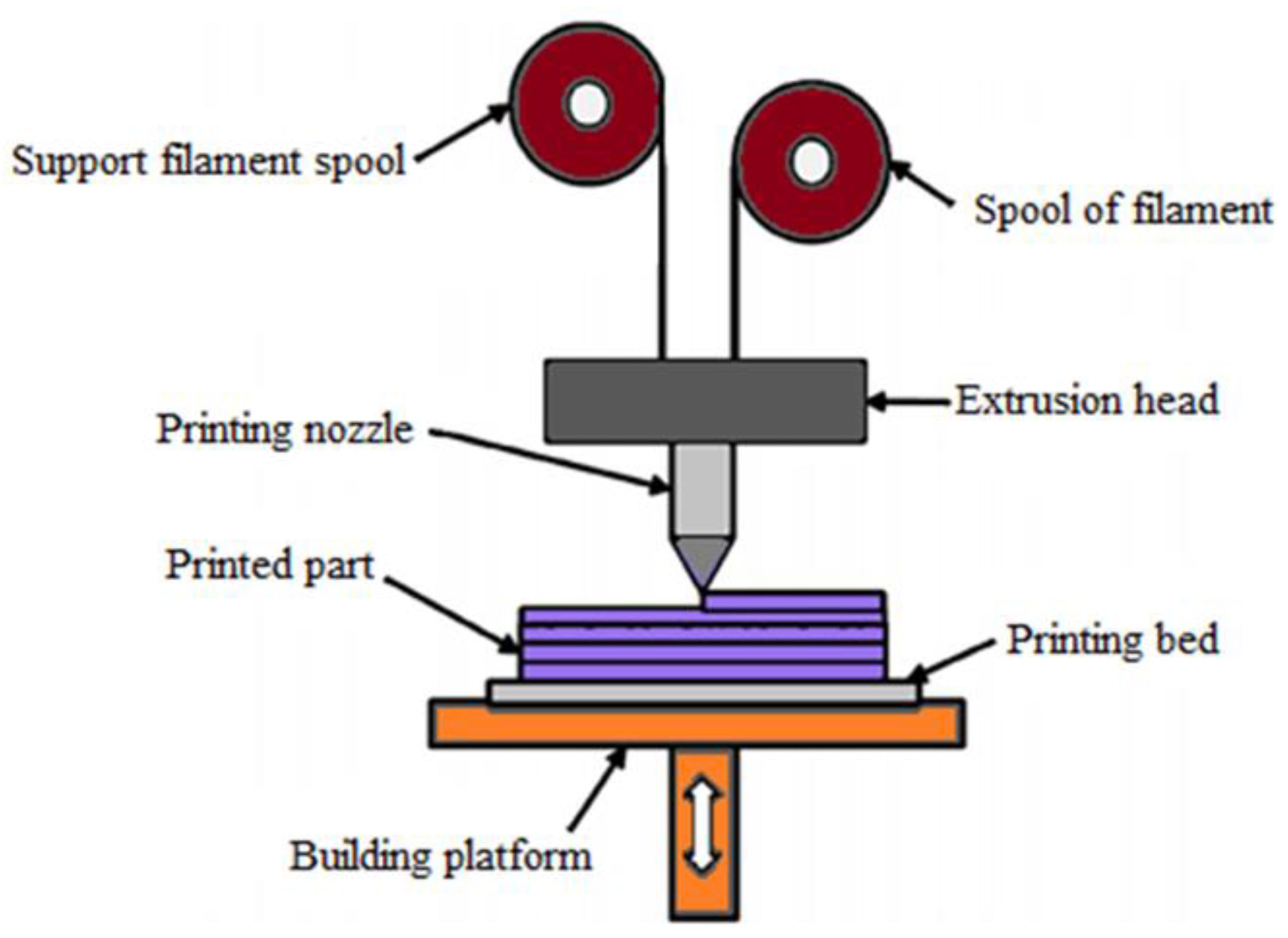
1. Introduction
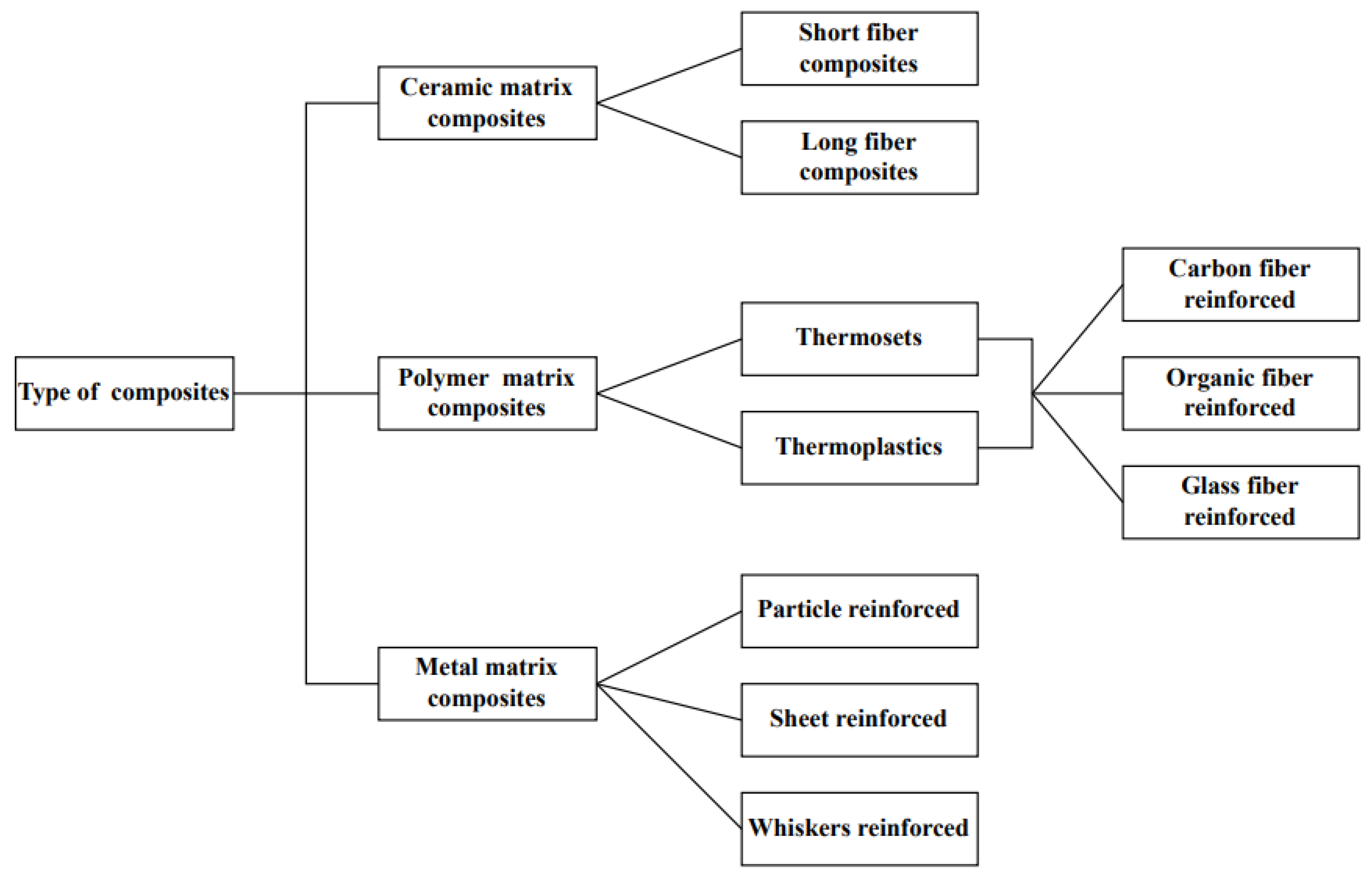
2. Composite Materials
2.1. Polymer Matrix Composite
2.2. Base Material

| References | Type of Materials | Characterisation | Utilisation Sector | Remarks |
|---|---|---|---|---|
| [54,55,56,57,58] | Acrylonitrile butadiene styrene (ABS) | Better resistance to corrosive materials Low cost Withstand high temperature | Microdevices Microfluidics Prototyping | Dissolves in acetone |
| [59,60,61,62,63,64,65] | Polylactic Acid (PLA) | Low cost Non-toxic Biodegradable Ease to print | Tissue engineering Automotive Electrical and Electromagnetic Biomedical Biosensors Prototyping | Very brittle Low toughness |
| [66,67,68] | Polyamide/Nylon | Resistant to impact Heat-resistant High tensile strength | Fabrication tools Prototyping Industrial production parts | Moisture accumulation |
| [69,70,71,72] | Polycarbonate (PC) | Transparent Temperature-resistant High resistance to impact | Dental Tissue engineering Orthopaedic | |
| [73,74] | Thermoplastic polyurethane (TPU) | Good lubricity Abrasion-resistant | Hoses and tubes Biomedical prototype Seals and gaskets | Elastomeric behaviour |
| [24,75,76,77,78] | Polyether-ether-ketone (PEEK) | Organic thermoplastic polymer Chemical-resistant Good lubricity | Aircraft parts Racing cars Drones Medical implants | |
| [79,80,81,82] | Polyethene terephthalate glycol (PETG) | Chemical-resistant Transparent High processability | Bone models Orthopaedics | Become brittle due to heat |
| [59,64] | Polyvinyl alcohol (PVA) | Soluble in water | Dental models Bioprinting Brackets | Affected by humidity |
| [83,84] | Polyetherimide (PEI) | Chemical-resistant Heat-resistant Dielectric | Aerospace Automotive Medical | Better than conventional plastic products |
2.3. Filler Material
3. Processing Parameter of FDM
3.1. Layer Height
3.2. Nozzle Temperature
3.3. Bed Temperature
3.4. Printing Speed
3.5. Building Orientation
3.6. Screw Type
3.6.1. Single Screw Extruder
3.6.2. Twin Screw Extruder

| Extrusion Type (Screw) | Extruder Model | Advantages | Disadvantages | Reference |
|---|---|---|---|---|
| Single | SJ-30/25, Zhangjiagang Grand | Cheap Simple design Low maintaining cost | Poor in mixing Not suitable for low heat-resistant materials | [169,170,171,172] |
| Twin | SJ-30/25, Zhangjiagang Grand APV Chemical Machinery MP 2015 DSM Xplore Haake Rheomex OS, Thermo Fisher, Germany | High dispersion capacity, which results in better mixing Better process parameters control Easy material feed Flexible and better productivity | Expensive Better input energy Not applicable for materials that are shear-sensitive | [171,172,173,174,175] |
4. Properties of FDM-Polymer Composite
4.1. Mechanical Analysis
4.2. Thermal Analysis
5. Application of Polymer Composite in 3D Printing
5.1. Aerospace
5.2. Automotive
5.3. Biomedical
5.4. Textile
5.5. Functional Materials
6. Future Trend/Challenges of FDM-Polymer Composite
7. Conclusions
- An overview of FDM process flow and polymer composite material properties, and the type of base and filler material commonly used in FDM.
- The printing parameters such as nozzle temperature, bed temperature, printing speed, building orientation, layer height, and screw type also play a significant role in the performance of the FDM-printed product. However, the relationship between printing quality and mechanical behaviour for the various types of materials used in FDM cannot be explained by the available data. There are currently no absolute laws and regulations that can be applied to help users improve the printing process to achieve the best printing results, because the same printing procedure can result in various printing outcomes if the material is different.
- Different polymers have different behaviours in terms of mechanical properties. Adding fillers to thermoplastic polymers can enhance the properties and strength of that particular polymer. Meanwhile, it is still rare to come across the improvement of process parameters for thermal, chemical, and dynamic mechanical properties.
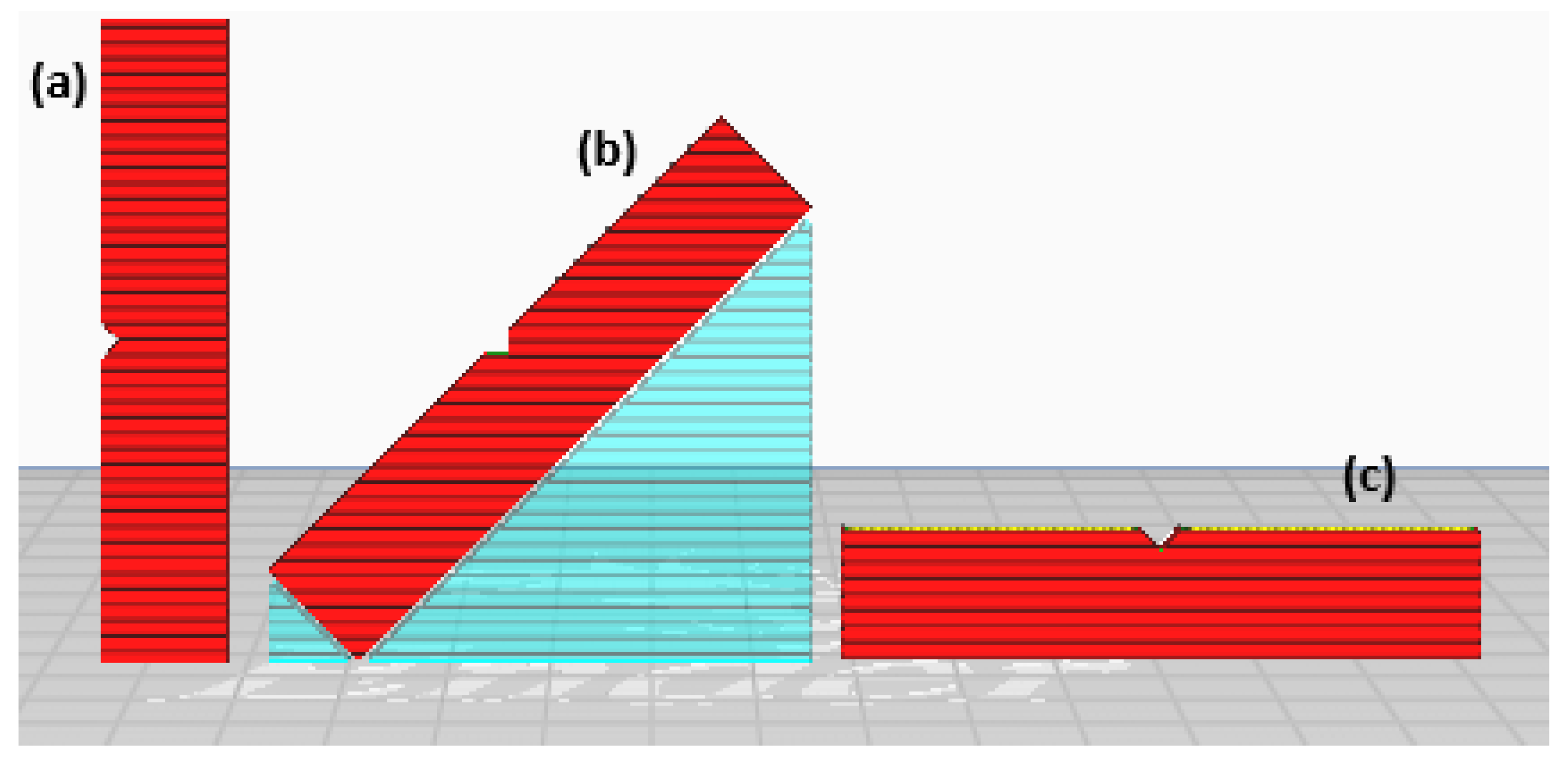
- The application of the FDM process in industries such as the aerospace, automobile, textile, and biomedical sectors is also explained briefly. However, in terms of large-scale applications, FDM still cannot be used as a substitute for the traditional technique, such as injection moulding, when analyzing the mechanical work performance achieved. The main issues with the FDM printing are porosity, gaps between layers, and rasters produced in the FDM process.
Author Contributions
Funding
Institutional Review Board Statement
Data Availability Statement
Acknowledgments
Conflicts of Interest
References
- Hart, K.R.; Wetzel, E.D. Fracture behavior of additively manufactured acrylonitrile butadiene styrene (ABS) materials. Eng. Fract. Mech. 2017, 177, 1–13. [Google Scholar] [CrossRef]
- Almuallim, B.; Harun, W.S.W.; Rikabi, I.J.R.; Mohammed, H.A. Thermally conductive polymer nanocomposites for filament-based additive manufacturing. J. Mater. Sci. 2022, 57, 3993–4019. [Google Scholar] [CrossRef]
- Patil, P.; Singh, D.; Raykar, S.J.; Bhamu, J. Multi-objective optimization of process parameters of Fused Deposition Modeling (FDM) for printing Polylactic Acid (PLA) polymer components. Mater. Today Proc. 2021, 45, 4880–4885. [Google Scholar] [CrossRef]
- Harun, W.S.W.; Kamariah, M.S.I.N.; Muhamad, N.; Ghani, S.A.C.; Ahmad, F.; Mohamed, Z. A review of powder additive manufacturing processes for metallic biomaterials. Powder Technol. 2018, 327, 128–151. [Google Scholar] [CrossRef]
- Kumar, R.; Kumar, M.; Chohan, J.S. The role of additive manufacturing for biomedical applications: A critical review. J. Manuf. Processes 2021, 64, 828–850. [Google Scholar] [CrossRef]
- Talib, S.; Gupta, S.; Chaudhary, V.; Gupta, P.; Wahid, M.A. Additive manufacturing: Materials, techniques and biomedical applications. Mater. Today Proc. 2021, 46, 6847–6851. [Google Scholar] [CrossRef]
- Blakey-Milner, B.; Gradl, P.; Snedden, G.; Brooks, M.; Pitot, J.; Lopez, E.; Leary, M.; Berto, F.; Plessis, A. Metal additive manufacturing in aerospace: A review. Mater. Des. 2021, 209, 110008. [Google Scholar] [CrossRef]
- Najmon, J.C.; Raeisi, S.; Tovar, A. Review of additive manufacturing technologies and applications in the aerospace industry. In Additive Manufacturing for the Aerospace Industry; Froes, F., Boyer, R., Eds.; Elsevier: Amsterdam, The Netherlands, 2019; pp. 7–31. [Google Scholar]
- Sargini, M.I.M.; Masood, S.H.; Palanisamy, S.; Jayamani, E.; Kapoor, A. Additive manufacturing of an automotive brake pedal by metal fused deposition modelling. Mater. Today Proc. 2021, 45, 4601–4605. [Google Scholar] [CrossRef]
- Jimeno-Morenilla, A.; Azariadis, P.; Molina-Carmona, R.; Kyratzi, S.; Moulianitis, V. Technology enablers for the implementation of Industry 4.0 to traditional manufacturing sectors: A review. Comput. Ind. 2021, 125, 103390. [Google Scholar] [CrossRef]
- Jayaraghul, T.K.; Karthik, K.; Yaswanth, A.; Venkatesan, M. Nozzle flow characteristics of P.E.E.K (Poly-ether ether ketone) material used in 3D-printing. Mater. Today Proc. 2021, 44, 2963–2967. [Google Scholar] [CrossRef]
- Deomore, S.A.; Raykar, S.J. Multi-criteria decision making paradigm for selection of best printing parameters of fused deposition modeling. Mater. Today Proc. 2021, 44, 2562–2565. [Google Scholar] [CrossRef]
- Stoia, D.I.; Marsavina, L. Effect of Aluminum Particles on the Fracture Toughness of Polyamide-based Parts Obtained by Selective Laser Sintering (SLS). Procedia Struct. Integr. 2019, 18, 163–169. [Google Scholar] [CrossRef]
- Khan, S.; Joshi, K.; Deshmukh, S. A comprehensive review on effect of printing parameters on mechanical properties of FDM printed parts. Mater. Today Proc. 2021, 50, 2119–2127. [Google Scholar] [CrossRef]
- Ahmed, N. Direct metal fabrication in rapid prototyping: A review. J. Manuf. Process. 2019, 42, 167–191. [Google Scholar] [CrossRef]
- Ahn, D.; Kweon, J.; Choi, J.; Lee, S. Quantification of surface roughness of parts processed by laminated object manufacturing. J. Mater. Process. Technol. 2012, 212, 339–346. [Google Scholar] [CrossRef]
- Derby, B. Additive Manufacture of Ceramics Components by Inkjet Printing. Engineering 2015, 1, 113–123. [Google Scholar] [CrossRef]
- Revilla-León, M.; Methani, M.M.; Morton, D.; Zandinejad, A. Internal and marginal discrepancies associated with stereolithography (SLA) additively manufactured zirconia crowns. J. Prosthet. Dent. 2020, 124, 730–737. [Google Scholar] [CrossRef]
- Giri, J.; Shahane, P.; Jachak, S.; Chadge, R.; Giri, P. Optimization of FDM process parameters for dual extruder 3d printer using Artificial Neural network. Mater. Today Proc. 2021, 43, 3242–3249. [Google Scholar] [CrossRef]
- Angelopoulos, P.M.; Samouhos, M.; Taxiarchou, M. Functional fillers in composite filaments for fused filament fabrication; a review. Mater. Today Proc. 2021, 37, 4031–4043. [Google Scholar] [CrossRef]
- Dehghan-Manshadi, A.; Yu, P.; Dargusch, M.; StJohn, D.; Qian, M. Metal injection moulding of surgical tools, biomaterials and medical devices: A review. Powder Technol. 2020, 364, 189–204. [Google Scholar] [CrossRef]
- Maurya, R.K.; Niranjan, M.S. An experimental analysis of process parameters for EN-36C alloy steel using CNC lathe—A review. Mater. Today Proc. 2020, 25, 773–777. [Google Scholar] [CrossRef]
- Doungkom, P.; Jiamjiroch, K. Analysis of Printing Pattern and Infiltration Percent over the Tensile Properties of PLA Printed Parts by a Fuse Deposition Modelling Printer. IOP Conf. Ser. Mater. Sci. Eng. 2019, 501, 012028. [Google Scholar] [CrossRef]
- Wickramasinghe, S.; Do, T.; Tran, P. FDM-based 3D printing of polymer and associated composite: A review on mechanical properties, defects and treatments. Polymers 2020, 12, 1529. [Google Scholar] [CrossRef]
- Thomas, S.; Joseph, K.; Malhotra, S.K.; Goda, K.; Sreekala, M.S. Polymer composites. In Macro- and Microcomposites; John Wiley & Sons: Hoboken, NJ, USA, 2012; Volume 1. [Google Scholar]
- Asim, M.; Saba, N.; Jawaid, M.; Nasir, M. Potential of natural fiber/biomass filler-reinforced polymer composites in aerospace applications. In Sustainable Composites for Aerospace Applications; Jawaid, M., Thariq, M., Eds.; Woodhead Publishing: Sawston, UK, 2018; pp. 253–268. [Google Scholar]
- Gavali, V.C.; Kubade, P.R.; Kulkarni, H.B. Property Enhancement of Carbon Fiber Reinforced Polymer Composites Prepared by Fused Deposition Modeling. Mater. Today Proc. 2020, 23, 221–229. [Google Scholar] [CrossRef]
- Shanmugam, V.; Rajendran, D.J.J.; Babu, K.; Rajendran, S.; Veerasimman, A.; Marimuthu, U.; Singh, S.; Das, O.; Neisiany, R.E.; Hedenqvist, M.S.; et al. The mechanical testing and performance analysis of polymer-fibre composites prepared through the additive manufacturing. Polym. Test. 2021, 93, 106925. [Google Scholar] [CrossRef]
- Vyavahare, S.; Teraiya, S.; Panghal, D.; Kumar, S. Fused deposition modelling: A review. Rapid Prototyp. J. 2020, 26, 176–201. [Google Scholar] [CrossRef]
- Singh, A.P.; Sharma, M.; Singh, I. A review of modeling and control during drilling of fiber reinforced plastic composites. Compos. Part B Eng. 2013, 47, 118–125. [Google Scholar] [CrossRef]
- Dandekar, C.R.; Shin, Y.C. Modeling of machining of composite materials: A review. Int. J. Mach. Tools Manuf. 2012, 57, 102–121. [Google Scholar] [CrossRef]
- Koli, D.K.; Agnihotri, G.; Purohit, R. Properties and characterization of Al-Al2O3 composites processed by casting and powder metallurgy routes. Int. J. Latest Trends Eng. Technol. (IJLTET) 2013, 2, 486–496. [Google Scholar]
- Clyne, T.W.; Hull, D. An Introduction to Composite Materials, 3rd ed.; Cambridge University Press: Cambridge, UK, 2019. [Google Scholar]
- Gibson, R.F. A review of recent research on mechanics of multifunctional composite materials and structures. Compos. Struct. 2010, 92, 2793–2810. [Google Scholar] [CrossRef]
- Mittal, V.; Saini, R.; Sinha, S. Natural fiber-mediated epoxy composites—A review. Compos. Part B Eng. 2016, 99, 425–435. [Google Scholar] [CrossRef]
- Qin, Q.; Ye, J. Toughening Mechanisms in Composite Materials; Elsevier: Amsterdam, The Netherlands, 2015. [Google Scholar]
- Cen, H.; Kang, Y.; Lei, Z.; Qin, Q.; Qiu, W. Micromechanics analysis of Kevlar-29 aramid fiber and epoxy resin microdroplet composite by Micro-Raman spectroscopy. Compos. Struct. 2006, 75, 532–538. [Google Scholar] [CrossRef]
- Qin, Q.H. Introduction to the composite and its toughening mechanisms. In Toughening Mechanisms in Composite Materials; Woodhead Publishing Series in Composites Science and Engineering; Woodhead Publishing: Sawston, UK, 2015; pp. 1–32. [Google Scholar]
- Tsai, S.W.; Hahn, H.T. Introduction to Composite Materials; Routledge: Boca Raton, FL, USA, 2018. [Google Scholar]
- Barbero, E.J. Introduction to Composite Materials Design; CRC press: Boca Raton, FL, USA, 2010. [Google Scholar]
- Ray, B. Temperature effect during humid ageing on interfaces of glass and carbon fibers reinforced epoxy composites. J. Colloid Interface Sci. 2006, 298, 111–117. [Google Scholar] [CrossRef]
- Xu, Y.; Chung, D.; Mroz, C. Thermally conducting aluminum nitride polymer-matrix composites. Compos. Part A Appl. Sci. Manuf. 2001, 32, 1749–1757. [Google Scholar] [CrossRef]
- Davim, J.P.; Reis, P. Study of delamination in drilling carbon fiber reinforced plastics (CFRP) using design experiments. Compos. Struct. 2003, 59, 481–487. [Google Scholar] [CrossRef]
- Mukherjee, M.; Das, C.; Kharitonov, A. Fluorinated and oxyfluorinated short Kevlar fiber-reinforced ethylene propylene polymer. Polym. Compos. 2006, 27, 205–212. [Google Scholar] [CrossRef]
- Dang, Z.-M.; Yuan, J.-K.; Zha, J.-W.; Zhou, T.; Li, S.T.; Hu, G.-H. Fundamentals, processes and applications of high-permittivity polymer–matrix composites. Prog. Mater. Sci. 2012, 57, 660–723. [Google Scholar] [CrossRef]
- Thoppul, S.D.; Finegan, J.; Gibson, R.F. Mechanics of mechanically fastened joints in polymer–matrix composite structures–a review. Compos. Sci. Technol. 2009, 69, 301–329. [Google Scholar] [CrossRef]
- Wisnom, M.R.; Gigliotti, M.; Ersoy, N.; Campbell, M.; Potter, K.D. Mechanisms generating residual stresses and distortion during manufacture of polymer–matrix composite structures. Compos. Part A Appl. Sci. Manuf. 2006, 37, 522–529. [Google Scholar] [CrossRef]
- Barekar, N.; Tzamtzis, S.; Dhindaw, B.K.; Patel, J.; Babu, N.H.; Fan, Z. Processing of aluminum-graphite particulate metal matrix composites by advanced shear technology. J. Mater. Eng. Perform. 2009, 18, 1230–1240. [Google Scholar] [CrossRef]
- Kök, M. Abrasive wear of Al2O3 particle reinforced 2024 aluminium alloy composites fabricated by vortex method. Compos. Part A Appl. Sci. Manuf. 2006, 37, 457–464. [Google Scholar] [CrossRef]
- Dixit, N.; Jain, P.K. 3D printed carbon fiber reinforced thermoplastic composites: A review. Mater. Today Proc. 2021, 43, 678–681. [Google Scholar] [CrossRef]
- Park, S.; Fu, K. Polymer-based filament feedstock for additive manufacturing. Compos. Sci. Technol. 2021, 213, 108876. [Google Scholar] [CrossRef]
- Lay, M.; Thajudin, N.L.N.; Hamid, Z.A.A.H.; Rusli, A.; Abdullah, M.K.; Shuib, R.K. Comparison of physical and mechanical properties of PLA, ABS and nylon 6 fabricated using fused deposition modeling and injection molding. Compos. Part B Eng. 2019, 176, 107341. [Google Scholar] [CrossRef]
- Penumakala, P.K.; Santo, J.; Thomas, A. A critical review on the fused deposition modeling of thermoplastic polymer composites. Compos. Part B Eng. 2020, 201, 108336. [Google Scholar] [CrossRef]
- Vlasceanu, D.; Baciu, F.; Popescu, D.; Hadar, H.; Marinescu, R. Development and 3D Printing of an ABS Ergonomic Handle for Medical Use. Mater. Plast. 2018, 55, 630. [Google Scholar] [CrossRef]
- Alhallak, L.M.; Tirkes, S.; Tayfun, U. Mechanical, thermal, melt-flow and morphological characterizations of bentonite-filled ABS copolymer. Rapid Prototyp. J. 2020, 26, 1305–1312. [Google Scholar] [CrossRef]
- Li, X.; Sun, L.; Aifantis, K.E.; Fan, Y.; Feng, Q.; Cui, F.; Watari, F. 3D-printed biopolymers for tissue engineering application. Int. J. Polym. Sci. 2014, 2014, 829145. [Google Scholar] [CrossRef]
- Fornells, E.; Murray, E.; Waheed, S.; Morrin, A.; Diamond, D.; Paull, B.; Breadmore, M. Integrated 3D printed heaters for microfluidic applications: Ammonium analysis within environmental water. Anal. Chim. Acta 2020, 1098, 94–101. [Google Scholar] [CrossRef]
- Raney, K.; Lani, E.; Kalla, D.K. Experimental characterization of the tensile strength of ABS parts manufactured by fused deposition modeling process. Mater. Today Proc. 2017, 4, 7956–7961. [Google Scholar] [CrossRef]
- Kamran, M.; Saxena, A. A comprehensive study on 3D printing technology. MIT Int. J. Mech. Eng. 2016, 6, 63–69. [Google Scholar]
- Zhang, D.; Chi, B.H.; Li, B.W.; Gao, Z.W.; Du, Y.; Guo, J.B.; Wei, J. Fabrication of highly conductive graphene flexible circuits by 3D printing. Synth. Met. 2016, 217, 79–86. [Google Scholar] [CrossRef]
- Tak, J.; Kang, D.G.; Choi, J. A lightweight waveguide horn antenna made via 3D printing and conductive spray coating. Microw. Opt. Technol. Lett. 2017, 59, 727–729. [Google Scholar] [CrossRef]
- Narayanan, L.K.; Huebner, P.; Fisher, M.B.; Spang, J.T.; Starly, B.; Shirwaiker, R.A. 3D-bioprinting of polylactic acid (PLA) nanofiber–alginate hydrogel bioink containing human adipose-derived stem cells. ACS Biomater. Sci. Eng. 2016, 2, 1732–1742. [Google Scholar] [CrossRef]
- Levato, R.; Visser, J.; Planell, J.A.; Engel, E.; Malda, J.; Mateos-Timoneda, M.A. Biofabrication of tissue constructs by 3D bioprinting of cell-laden microcarriers. Biofabrication 2014, 6, 035020. [Google Scholar] [CrossRef]
- Li, T.J.; Aspler, J.; Kingsland, A.; Cormier, L.M.; Zou, X.J. 3d printing–a review of technologies, markets, and opportunities for the forest industry. J. Sci. Technol. For. Prod. Process 2016, 5, 30. [Google Scholar]
- Muñoz, J.; Pumera, M. 3D-printed biosensors for electrochemical and optical applications. TrAC Trends Anal. Chem. 2020, 128, 115933. [Google Scholar] [CrossRef]
- Aslanzadeh, S.; Saghlatoon, H.; Honari, M.M.; Mirzavand, R.; Montemagno, C.; Mousavi, P. Investigation on electrical and mechanical properties of 3D printed nylon 6 for RF/microwave electronics applications. Addit. Manuf. 2018, 21, 69–75. [Google Scholar] [CrossRef]
- Calignano, F.; Lorusso, M.; Roppolo, I.; Minetola, P. Investigation of the Mechanical Properties of a Carbon Fibre-Reinforced Nylon Filament for 3D Printing. Machines 2020, 8, 52. [Google Scholar] [CrossRef]
- Farina, I.; Singh, N.; Colangelo, F.; Luciano, R.; Bonazzi, G.; Fraternali, F. High-performance nylon-6 sustainable filaments for additive manufacturing. Materials 2019, 12, 3955. [Google Scholar] [CrossRef]
- Tambrallimath, V.; Keshavamurthy, R.; Saravanabavan, D.; Koppad, P.G.; Kumar, G.P. Thermal behavior of PC-ABS based graphene filled polymer nanocomposite synthesized by FDM process. Compos. Commun. 2019, 15, 129–134. [Google Scholar] [CrossRef]
- Tambrallimath, V.; Keshavamurthy, R.; Saravanabavan, D.; Koppad, P.G.; Sethuram, D. Mechanical characterization of PC-ABS reinforced with CNT nanocomposites developed by fused deposition modelling. J. Phys. Conf. Ser. IOP Publ. 2020, 1455, 012003. [Google Scholar] [CrossRef]
- Roberson, D.; Shemelya, C.M.; MacDonald, E.; Wicker, R. Expanding the applicability of FDM-type technologies through materials development. Rapid Prototyp. J. 2015, 21, 137–143. [Google Scholar] [CrossRef]
- Park, S.J.; Lee, J.E.; Lee, H.B.; Park, J.; Lee, N.K.; Son, Y.; Park, S.H. 3D printing of bio-based polycarbonate and its potential applications in ecofriendly indoor manufacturing. Addit. Manuf. 2020, 31, 100974. [Google Scholar] [CrossRef]
- Geng, Y.; He, H.; Liu, H. Preparation of polycarbonate/poly (lactic acid) with improved printability and processability for fused deposition modeling. Polym. Adv. Technol. 2020, 31, 2848–2862. [Google Scholar] [CrossRef]
- Revilla-León, M.; Özcan, M. Additive manufacturing technologies used for processing polymers: Current status and potential application in prosthetic dentistry. J. Prosthodont. 2019, 28, 146–158. [Google Scholar] [CrossRef]
- Georgopoulou, A.; Sebastian, T.; Clemens, F. Thermoplastic elastomer composite filaments for strain sensing applications extruded with a fused deposition modelling 3D printer. Flex. Print. Electron. 2020, 5, 035002. [Google Scholar] [CrossRef]
- Haryńska, A.; Gubanska, I.; Kucinnska-Lipka, J.; Janik, H. Fabrication and characterization of flexible medical-grade TPU filament for fused deposition modeling 3DP technology. Polymers 2018, 10, 1304. [Google Scholar] [CrossRef]
- Wang, P.; Zou, B.; Ding, S.L.; Huang, C.Z.; Shi, Z.Y.; Ma, Y.S.; Yao, P. Preparation of short CF/GF reinforced PEEK composite filaments and their comprehensive properties evaluation for FDM-3D printing. Compos. Part B Eng. 2020, 198, 108175. [Google Scholar] [CrossRef]
- Wang, P.; Zou, B.; Xiao, H.C.; Ding, S.L.; Huang, C.Z. Effects of printing parameters of fused deposition modeling on mechanical properties, surface quality, and microstructure of PEEK. J. Mater. Process. Technol. 2019, 271, 62–74. [Google Scholar] [CrossRef]
- Rinaldi, M.; Cecchini, F.; Pigliaru, L.; Ghidini, T.; Lumaca, F.; Nanni, F. Additive manufacturing of polyether ether ketone (PEEK) for space applications: A nanosat polymeric structure. Polymers 2021, 13, 11. [Google Scholar] [CrossRef]
- Liu, Z.; Wang, G.; Huo, Y.; Zhao, W. Research on precise control of 3D print nozzle temperature in PEEK material. AIP Conf. Proc. 2017, 1890, 040076. [Google Scholar]
- Haffner, M.; Quinn, A.; Hsieh, T.Y.; Strong, E.B.; Steele, T. Optimization of 3D print material for the recreation of patient-specific temporal bone models. Ann. Otol. Rhinol. Laryngol. 2018, 127, 338–343. [Google Scholar] [CrossRef] [PubMed]
- Capel, A.J.; Rimington, R.P.; Lewis, M.P.; Christie, S.D. 3D printing for chemical, pharmaceutical and biological applications. Nat. Rev. Chem. 2018, 2, 422–436. [Google Scholar] [CrossRef]
- Redaelli, D.F.; Abbate, V.; Storm, F.A.; Ronca, A.; Sorrentino, A.; Capitani, C.D.; Biffi, E.; Ambrosio, L.; Colombo, G.; Fraschini, P. 3D printing orthopedic scoliosis braces: A test comparing FDM with thermoforming. Int. J. Adv. Manuf. Technol. 2020, 111, 1707–1720. [Google Scholar] [CrossRef]
- Subbarao, C.V.; Reddy, Y.S.; Inturi, V.; Reddy, M.I. Dynamic Mechanical Analysis of 3D Printed PETG Material. IOP Conf. Ser. Mater. Sci. Eng. 2021, 1057, 012031. [Google Scholar] [CrossRef]
- Blanco, I.; Rapisarda, M.; Portuesi, S.; Ognibene, G.; Cicala, G. Thermal behavior of PEI/PETG blends for the application in fused deposition modelling (FDM). AIP Conf. Proc. 2018, 1981, 020181. [Google Scholar]
- Cicala, G.; Ognibene, G.; Portuesi, S.; Blanco, I.; Rapisarda, M.; Pergolizzi, E.; Recca, G. Comparison of Ultem 9085 used in fused deposition modelling (FDM) with polytherimide blends. Materials 2018, 11, 285. [Google Scholar] [CrossRef]
- Zhang, X.; Chen, L. Effects of laser scanning speed on surface roughness and mechanical properties of aluminum/Polylactic Acid (Al/PLA) composites parts fabricated by fused deposition modeling. Polym. Test. 2020, 91, 106785. [Google Scholar] [CrossRef]
- Zhang, X.; Chen, L.; Mulholland, T.; Osswald, T.A. Effects of raster angle on the mechanical properties of PLA and Al/PLA composite part produced by fused deposition modeling. Polym. Adv. Technol. 2019, 30, 2122–2135. [Google Scholar] [CrossRef]
- Vardhan, H.; Kumar, R.; Chohan, J.S. Investigation of tensile properties of sprayed aluminium based PLA composites fabricated by FDM technology. Mater. Today Proc. 2020, 33, 1599–1604. [Google Scholar] [CrossRef]
- Pavan, M.V.; Balamurugan, K.; Balamurugan, P. Compressive test Fractured Surface analysis on PLA-Cu composite filament printed at different FDM conditions. IOP Conf. Ser. Mater. Sci. Eng. 2020, 988, 012019. [Google Scholar] [CrossRef]
- Balamurugan, K.; Pavan, M.V.; Ali, S.A.; Kalusuraman, G. Compression and flexural study on PLA-Cu composite filament using FDM. Mater. Today Proc. 2021, 44, 1687–1691. [Google Scholar] [CrossRef]
- Gong, H.; Snelling, D.; Kardel, K.; Carrano, A. Comparison of Stainless Steel 316L Parts Made by FDM- and SLM-Based Additive Manufacturing Processes. JOM 2018, 71, 880–885. [Google Scholar] [CrossRef]
- Daver, F.; Lee, K.P.M.; Brandt, M.; Shanks, R. Cork–PLA composite filaments for fused deposition modelling. Compos. Sci. Technol. 2018, 168, 230–237. [Google Scholar] [CrossRef]
- da Silva, S.P.M.; Antunes, T.; Costa, M.E.V.; Oliveira, J.M. Cork-like filaments for Additive Manufacturing. Addit. Manuf. 2020, 34, 101229. [Google Scholar]
- Le Duigou, A.; Castro, M.; Bevan, R.; Martin, N. 3D printing of wood fibre biocomposites: From mechanical to actuation functionality. Mater. Des. 2016, 96, 106–114. [Google Scholar] [CrossRef]
- Ayrilmis, N.; Kariz, M.; Kwon, J.H.; Kuzman, M.K. Effect of printing layer thickness on water absorption and mechanical properties of 3D-printed wood/PLA composite materials. Int. J. Adv. Manuf. Technol. 2019, 102, 2195–2200. [Google Scholar] [CrossRef]
- Liu, Z.; Lei, Q.; Xing, S. Mechanical characteristics of wood, ceramic, metal and carbon fiber-based PLA composites fabricated by FDM. J. Mater. Res. Technol. 2019, 8, 3741–3751. [Google Scholar] [CrossRef]
- Kumar, S.D.; Venkadeshwaran, K.; Aravindan, M. Fused deposition modelling of PLA reinforced with cellulose nano-crystals. Mater. Today Proc. 2020, 33, 868–875. [Google Scholar] [CrossRef]
- Wang, Z.; Xu, J.; Lu, Y.; Ma, J.; Zhou, X. Preparation of 3D printable micro/nanocellulose-polylactic acid (MNC/PLA) composite wire rods with high MNC constitution. Ind. Crops Prod. 2017, 109, 889–896. [Google Scholar] [CrossRef]
- Zhang, Y.; Cui, L.; Xu, H.; Feng, X.; Wang, B.; Pukánszky, B. Poly(lactic acid)/cellulose nanocrystal composites via the Pickering emulsion approach: Rheological, thermal and mechanical properties. Int. J. Biol. Macromol. 2019, 137, 197–204. [Google Scholar] [CrossRef] [PubMed]
- Zhang, X.; Shi, J.; Ye, H.; Dong, Y.; Zhou, Q. Combined effect of cellulose nanocrystals and poly (butylene succinate) on poly (lactic acid) crystallization: The role of interfacial affinity. Carbohydr. Polym. 2018, 179, 79–85. [Google Scholar] [CrossRef] [PubMed]
- Schmitz, D.P.; Ecco, L.G.; Dul, S.; Pereira, E.C.L.; Soares, B.G.; Barra, G.M.O.; Pegoretti, A. Electromagnetic interference shielding effectiveness of ABS carbon-based composites manufactured via fused deposition modelling. Mater. Today Commun. 2018, 15, 70–80. [Google Scholar] [CrossRef]
- Dawoud, M.; Taha, I.; Ebeid, S.J. Strain sensing behaviour of 3D printed carbon black filled ABS. J. Manuf. Processes 2018, 35, 337–342. [Google Scholar] [CrossRef]
- Sanatgar, R.H.; Campagne, C.; Nierstrasz, V. Investigation of the adhesion properties of direct 3D printing of polymers and nanocomposites on textiles: Effect of FDM printing process parameters. Appl. Surf. Sci. 2017, 403, 551–563. [Google Scholar] [CrossRef]
- Tirado-Garcia, I.; Garcia-Gonzalez, D.; Garzon-Hernandez, S.; Rusinek, A.; Robles, G.; Martinez-Tarifa, J.M.; Arias, A. Conductive 3D printed PLA composites: On the interplay of mechanical, electrical and thermal behaviours. Compos. Struct. 2021, 265, 113744. [Google Scholar] [CrossRef]
- Abdalla, A.; Hamzah, H.H.; Keattch, O.; Covill, D.; Patel, B.A. Augmentation of conductive pathways in carbon black/PLA 3D-printed electrodes achieved through varying printing parameters. Electrochim. Acta 2020, 354, 136618. [Google Scholar] [CrossRef]
- Dul, S.; Fambri, L.; Pegoretti, A. Fused deposition modelling with ABS–graphene nanocomposites. Compos. Part A Appl. Sci. Manuf. 2016, 85, 181–191. [Google Scholar] [CrossRef]
- Sakunphokesup, K.; Kongkrengki, P.; Pongwisuthiruchte, A.; Aumnate, C.; Potiyaraj, P. Graphene-enhanced ABS for FDM 3D printing: Effects of masterbatch preparation techniques. IOP Conf. Ser. Mater. Sci. Eng. 2019, 600, 012001, IOP Publishing. [Google Scholar] [CrossRef]
- Waheed, Q.; Khan, A.N.; Jan, R. Investigating the reinforcement effect of few layer graphene and multi-walled carbon nanotubes in acrylonitrile-butadiene-styrene. Polymer 2016, 97, 496–503. [Google Scholar] [CrossRef]
- Singh, R.; Sandhu, G.S.; Penna, R.; Farina, I. Investigations for thermal and electrical conductivity of ABS-graphene blended prototypes. Materials 2017, 10, 881. [Google Scholar] [CrossRef] [PubMed]
- Tambrallimath, V.; Keshavamurthy, R.; Saravanbavan, D.; Kumar, G.P.; Kumar, M.H. Synthesis and characterization of graphene filled PC-ABS filament for FDM applications. AIP Conf. Proc. 2019, 2057, 020039, AIP Publishing LLC. [Google Scholar]
- Wang, F.; Zhang, Y.; Zhang, B.B.; Hong, R.Y.; Kumar, M.R.; Xie, C.R. Enhanced electrical conductivity and mechanical properties of ABS/EPDM composites filled with graphene. Compos. Part B Eng. 2015, 83, 66–74. [Google Scholar] [CrossRef]
- Jyoti, J.; Basu, S.; Singh, B.P.; Dhakate, S.R. Superior mechanical and electrical properties of multiwall carbon nanotube reinforced acrylonitrile butadiene styrene high performance composites. Compos. Part B Eng. 2015, 83, 58–65. [Google Scholar] [CrossRef]
- Rodríguez-Vidal, E.; Quintana, I.; Gadea, C. Laser transmission welding of ABS: Effect of CNTs concentration and process parameters on material integrity and weld formation. Opt. Laser Technol. 2014, 57, 194–201. [Google Scholar] [CrossRef]
- Sanatgar, R.H.; Cayla, A.; Campagne, C.; Nierstrasz, V. Morphological and electrical characterization of conductive polylactic acid based nanocomposite before and after FDM 3D printing. J. Appl. Polym. Sci. 2019, 136, 47040. [Google Scholar] [CrossRef]
- Shao, S.; Zhou, S.; Li, L.; Li, J.; Luo, C.; Wang, J.; Li, X.; Weng, J. Osteoblast function on electrically conductive electrospun PLA/MWCNTs nanofibers. Biomaterials 2011, 32, 2821–2833. [Google Scholar] [CrossRef]
- Wu, D.; Spanou, A.; Diez-Escudero, A.; Persson, C. 3D-printed PLA/HA composite structures as synthetic trabecular bone: A feasibility study using fused deposition modeling. J. Mech. Behav. Biomed. Mater. 2020, 103, 103608. [Google Scholar] [CrossRef]
- Corcione, C.E.; Gervaso, F.; Scalera, F.; Montagna, F.; Maiullaro, T.; Sannino, A.; Maffezzoli, A. 3D printing of hydroxyapatite polymer-based composites for bone tissue engineering. J. Polym. Eng. 2017, 37, 741–746. [Google Scholar] [CrossRef]
- Pierantozzi, D.; Scalzone, A.; Jindal, S.; Stipniece, L.; Salma-Ancane, K.; Dalgano, K.; Gentile, P.; Mancuso, E. 3D printed Sr-containing composite scaffolds: Effect of structural design and material formulation towards new strategies for bone tissue engineering. Compos. Sci. Technol. 2020, 19, 108069. [Google Scholar] [CrossRef]
- Zhao, J.; Guo, L.Y.; Yang, X.B.; Weng, J. Preparation of bioactive porous HA/PCL composite scaffolds. Appl. Surf. Sci. 2008, 255, 2942–2946. [Google Scholar] [CrossRef]
- Heo, S.J.; Kim, S.E.; Wei, J.; Hyun, Y.T.; Yun, H.S.; Kim, D.H.; Shin, J.W.; Shin, J.W. Fabrication and characterization of novel nano-and micro-HA/PCL composite scaffolds using a modified rapid prototyping process. J. Biomed. Mater. Res. Part A Off. J. Soc. Biomater. Jpn. Soc. Biomater. Aust. Soc. Biomater. Korean Soc. Biomater. 2009, 89, 108–116. [Google Scholar] [CrossRef]
- Manzoor, F.; Golbang, A.; Jindal, S.; Dixon, D.; Mcllhagger, A.; Harkin-Jones, E.; Crawford, D.; Mancuso, E. 3D printed PEEK/HA composites for bone tissue engineering applications: Effect of material formulation on mechanical performance and bioactive potential. J. Mech. Behav. Biomed. Mater. 2021, 121, 104601. [Google Scholar] [CrossRef] [PubMed]
- Sang, L.; Han, S.; Li, Z.; Yang, X.; Hou, W. Development of short basalt fiber reinforced polylactide composites and their feasible evaluation for 3D printing applications. Compos. Part B Eng. 2019, 164, 629–639. [Google Scholar] [CrossRef]
- Nagendra, J.; Prasad, M.G.; Shashank, S.; Vijay, N.; Ali, S.M.; Suresh, V. Nylon-aramid polymer composite as sliding liner for lube-less sliding bearing by fused deposition modeling. AIP Conf. Proc. 2019, 2057, 020047. [Google Scholar]
- Le Duigou, A.; Barbe, A.; Guilou, E.; Castro, M. 3D printing of continuous flax fibre reinforced biocomposites for structural applications. Mater. Des. 2019, 180, 107884. [Google Scholar] [CrossRef]
- Bilkar, D.; Keshavamurthy, R.; Tambrallimath, V. Influence of carbon nanofiber reinforcement on mechanical properties of polymer composites developed by FDM. Mater. Today Proc. 2021, 46, 4559–4562. [Google Scholar] [CrossRef]
- Ning, F.; Cong, W.L.; Qiu, J.J.; Wei, J.H.; Wang, S.R. Additive manufacturing of carbon fiber reinforced thermoplastic composites using fused deposition modeling. Compos. Part B Eng. 2015, 80, 369–378. [Google Scholar] [CrossRef]
- Yu, N.; Sun, X.Y.; Wang, Z.; Zhang, D.J.; Li, J. Effects of auxiliary heat on warpage and mechanical properties in carbon fiber/ABS composite manufactured by fused deposition modeling. Mater. Des. 2020, 195, 108978. [Google Scholar] [CrossRef]
- Tandon, S.; Kacker, R.; Sudhakar, K. Experimental investigation on tensile properties of the polymer and composite specimens printed in a Triangular pattern. J. Manuf. Process. 2021, 68, 706–715. [Google Scholar] [CrossRef]
- Yu, Y.; Liu, H.L.; Qian, K.R.; Yang, H.; McGehee, M.; Gu, J.Z.; Luo, D.L.; Yao, L.N.; Zhang, Y.J. Material characterization and precise finite element analysis of fiber reinforced thermoplastic composites for 4D printing. Comput.-Aided Des. 2020, 122, 102817. [Google Scholar] [CrossRef]
- Gavali, V.C.; Kubade, P.R.; Kulkarni, H.B. Mechanical and thermo-mechanical properties of carbon fiber reinforced thermoplastic composite fabricated using fused deposition modeling method. Mater. Today Proc. 2020, 22, 1786–1795. [Google Scholar] [CrossRef]
- Kamaal, M.; Anas, M.; Rastogi, H.; Bhardwaj, N.; Rahaman, A. Effect of FDM process parameters on mechanical properties of 3D-printed carbon fibre–PLA composite. Prog. Addit. Manuf. 2021, 6, 63–69. [Google Scholar] [CrossRef]
- Lin, L.; Schlarb, A.K. Recycled carbon fibers as reinforcements for hybrid PEEK composites with excellent friction and wear performance. Wear 2019, 432, 202928. [Google Scholar] [CrossRef]
- Stepashkin, A.; Chukov, D.I.; Senatov, F.S.; Salimon, A.I.; Korsunsky, A.M.; Kaloshkin, S.D. 3D-printed PEEK-carbon fiber (CF) composites: Structure and thermal properties. Compos. Sci. Technol. 2018, 164, 319–326. [Google Scholar] [CrossRef]
- Huang, H.; Liu, W.; Liu, Z. An additive manufacturing-based approach for carbon fiber reinforced polymer recycling. CIRP Ann. 2020, 69, 33–36. [Google Scholar] [CrossRef]
- Prajapati, A.R.; Dave, H.K.; Raval, H.K. An Experimental Study on Mechanical, Thermal and Flame-Retardant Properties of 3D-Printed Glass-Fiber-Reinforced Polymer Composites. J. Mater. Eng. Perform. 2021, 30, 5266–5277. [Google Scholar] [CrossRef]
- Caminero, M.; Chacon, J.M.; Gracia-Moreno, I.; Rodriguez, G.P. Impact damage resistance of 3D printed continuous fibre reinforced thermoplastic composites using fused deposition modelling. Compos. Part B Eng. 2018, 148, 93–103. [Google Scholar] [CrossRef]
- Dickson, A.N.; Barry, J.N.; McDonnell, K.A.; Dowling, D.P. Fabrication of continuous carbon, glass and Kevlar fibre reinforced polymer composites using additive manufacturing. Addit. Manuf. 2017, 16, 146–152. [Google Scholar] [CrossRef]
- de Toro, E.V.; Sobrino, J.C.; Martinez, A.M.; Eguia, V.M. Analysis of the influence of the variables of the Fused Deposition Modeling (FDM) process on the mechanical properties of a carbon fiber-reinforced polyamide. Procedia Manuf. 2019, 41, 731–738. [Google Scholar] [CrossRef]
- Barrios, J.M.; Romero, P.E. Improvement of Surface Roughness and Hydrophobicity in PETG Parts Manufactured via Fused Deposition Modeling (FDM): An Application in 3D Printed Self–Cleaning Parts. Materials 2019, 12, 2499. [Google Scholar] [CrossRef] [PubMed]
- Zharylkassyn, B.; Perveen, A.; Talamona, D. Effect of process parameters and materials on the dimensional accuracy of FDM parts. Mater. Today Proc. 2020, 44, 1307–1311. [Google Scholar] [CrossRef]
- Nancharaiah, T.; Raju, D.R.; Raju, V.R. An experimental investigation on surface quality and dimensional accuracy of FDM components. Int. J. Emerg. Technol. 2010, 1, 106–111. [Google Scholar]
- Dey, A.; Yodo, N. A Systematic Survey of FDM Process Parameter Optimization and Their Influence on Part Characteristics. J. Manuf. Mater. Process. 2019, 3, 64. [Google Scholar] [CrossRef]
- Wang, T.M.; Xi, J.T.; Jin, Y. A model research for prototype warp deformation in the FDM process. Int. J. Adv. Manuf. Technol. 2007, 33, 1087–1096. [Google Scholar] [CrossRef]
- van Manen, T.; Janbaz, S.; Zadpoor, A.A. Programming the shape-shifting of flat soft matter. Mater. Today 2018, 21, 144–163. [Google Scholar] [CrossRef]
- Redwood, B.; Schöffer, F.; Garret, B. The 3D Printing Handbook: Technologies, Design and Applications; 3D Hubs: Amsterdam, The Netherlands, 2017. [Google Scholar]
- Kaur, G.; Singari, R.M.; Kumar, H. A review of fused filament fabrication (FFF): Process parameters and their impact on the tribological behavior of polymers (ABS). Mater. Today Proc. 2021, 51, 854–860. [Google Scholar] [CrossRef]
- Afrose, M.F.; Masood, S.H.; Ioveniti, P.; Nikzad, M.; Sbarski, I. Effects of part build orientations on fatigue behaviour of FDM-processed PLA material. Prog. Addit. Manuf. 2016, 1, 21–28. [Google Scholar] [CrossRef]
- Patil, H.; Tiwari, R.V.; Repka, M.A. Hot-melt extrusion: From theory to application in pharmaceutical formulation. AAPS PharmSciTech 2016, 17, 20–42. [Google Scholar] [CrossRef]
- Gaspar-Cunha, A.; Covas, J.A.; Costa, M.; Fernanda, P.; Costa, L. Optimization of Single Screw Extrusion; Technicka Univerzita Kosice: Košice, Slovakia, 2018. [Google Scholar]
- Maniruzzaman, M.; Boateng, J.S.; Snowden, M.J.; Douroumis, D. A review of hot-melt extrusion: Process technology to pharmaceutical products. Int. Sch. Res. Not. 2012, 2012, 436763. [Google Scholar] [CrossRef] [PubMed]
- Singhal, S.; Lohar, V.K.; Arora, V. Hot Melt Extrusion Technique. Webmedcentral Pharm. Sci. 2011, 2, 1. [Google Scholar]
- Chokshi, R.; Zia, H. Hot-melt extrusion technique: A review. Iran. J. Pharm. Res. 2004, 3, 3–16. [Google Scholar]
- Censi, R.; Gigliobianco, M.R.; Casadidio, C. Hot Melt Extrusion: Highlighting Physicochemical Factors to Be Investigated While Designing and Optimizing a Hot Melt Extrusion Process. Pharmaceutics 2018, 10, 89. [Google Scholar] [CrossRef] [PubMed]
- Abeykoon, C. Polymer Extrusion: A Study on Thermal Monitoring Techniques and Melting Issues, 1st ed.; LAP LAMBERT Academic Publishing: Berlin, Germany, 2012. [Google Scholar]
- Wilczyński, K.J.; Lewandowski, A.; Nastaj, A.; Wilczyriski, K. Modeling for Starve Fed/Flood Fed Mixing Single-Screw Extruders. Int. Polym. Process. 2016, 31, 82–91. [Google Scholar] [CrossRef]
- Repka, M.A.; Langley, N.; DiNunzio, J. Melt Extrusion: Materials, Technology and Drug Product Design; Springer Science & Business Media: New York, NY, USA, 2013; Volume 9. [Google Scholar]
- Geus, H.G. Developments in manufacturing techniques for technical nonwovens. In Advances in Technical Nonwovens; Woodhead Publishing: Sawston, UK, 2016; pp. 133–153. [Google Scholar]
- Wilczyński, K.; Nastaj, A.; Wilczyński, K.J. Melting Model for Starve Fed Single Screw Extrusion of Thermoplastics. Int. Polym. Process. 2013, 28, 34–42. [Google Scholar] [CrossRef]
- Wilczyński, K.; Lewandowski, A.; Wilczyński, K.J. Experimental study for starve-fed single screw extrusion of thermoplastics. Polym. Eng. Sci. 2012, 52, 1258–1270. [Google Scholar] [CrossRef]
- Tan, D.K.; Maniruzzaman, M.; Nokhodchi, A. Advanced Pharmaceutical Applications of Hot-Melt Extrusion Coupled with Fused Deposition Modelling (FDM) 3D Printing for Personalised Drug Delivery. Pharmaceutics 2018, 10, 203. [Google Scholar] [CrossRef]
- Wilczynski, K.; White, J.L. Melting Model for Intermeshing Counter-Rotating Twin-Screw Extruders. Polym. Eng. Sci. 2003, 43, 1715–1726. [Google Scholar] [CrossRef]
- Bouvier, J.M.; Campanella, O.H. Extrusion Processing Technology: Food and Non-Food Biomaterials; John Wiley & Sons: Hoboken, NJ, USA, 2014. [Google Scholar]
- Tadmor, Z.; Gogos, C.G. Principles of Polymer Processing; John Wiley & Sons: Hoboken, NJ, USA, 2013. [Google Scholar]
- Crowley, M.M.; Zhang, F.; Repka, M.A.; Thumma, S.; Upadhye, S.B.; Battu, S.K.; McGinity, J.W.; Martin, C. Pharmaceutical Applications of Hot-Melt Extrusion: Part I. Drug Dev. Ind. Pharm. 2007, 33, 909–926. [Google Scholar] [CrossRef]
- Wilczyński, K.; Lewandowski, A.; Wilczynski, K.J. Experimental study of melting of LDPE/PS polyblend in an intermeshing counter-rotating twin screw extruder. Polym. Eng. Sci. 2012, 52, 449–458. [Google Scholar] [CrossRef]
- Wilson, M.; Williams, M.A.; Jones, D.S.; Andrews, G.P. Hot-melt extrusion technology and pharmaceutical application. Ther. Deliv. 2012, 3, 787–797. [Google Scholar] [CrossRef] [PubMed]
- Uitterhaegen, E.; Evon, P. Twin-screw extrusion technology for vegetable oil extraction: A review. J. Food Eng. 2017, 212, 190–200. [Google Scholar] [CrossRef]
- Singh, R.; Singh, S. Development of nylon based FDM filament for rapid tooling application. J. Instittion Eng. 2014, 95, 103–108. [Google Scholar] [CrossRef]
- Osman, M.A.; Atia, M.R.A. Investigation of ABS-rice straw composite feedstock filament for FDM. Rapid Prototyp. J. 2018, 24, 6. [Google Scholar] [CrossRef]
- Weng, Z.; Wang, J.; Senthil, T.; Wu, L. Mechanical and thermal properties of ABS/montmorillonite nanocomposites for fused deposition modeling 3D printing. Mater. Des. 2016, 102, 276–283. [Google Scholar] [CrossRef]
- Boparai, K.S.; Singh, R.; Singh, H. Experimental investigations for development of Nylon6-Al-Al2O3 alternative FDM filament. Rapid Prototyp. J. 2016, 22, 2. [Google Scholar] [CrossRef]
- Melocchi, A.; Parietti, F.; Loreti, G.; Maroni, A.; Gazzaniga, A.; Zema, L. 3D printing by fused deposition modeling (FDM) of a swellable/erodible capsular device for oral pulsatile release of drugs. J. Drug Deliv. Sci. Technol. 2015, 30, 360–367. [Google Scholar] [CrossRef]
- Sezer, H.K.; Eren, O. FDM 3D printing of MWCNT re-inforced ABS nano-composite parts with enhanced mechanical and electrical properties. J. Manuf. Processes 2019, 37, 339–347. [Google Scholar] [CrossRef]
- Kuo, C.C.; Liu, L.C.; Teng, W.F.; Chang, H.Y.; Cchien, F.M.; Liao, S.J.; Kuo, W.F.; Chen, C.M. Preparation of starch/acrylonitrile-butadiene-styrene copolymers (ABS) biomass alloys and their feasible evaluation for 3D printing applications. Compos. Part B Eng. 2016, 86, 36–39. [Google Scholar] [CrossRef]
- Ahn, S.H.; Montero, M.; Odell, D.; Roundy, S.; Wright, P.K. Anisotropic material properties of fused deposition modeling ABS. Rapid Prototyp. J. 2002, 8, 4. [Google Scholar] [CrossRef]
- Nabipour, M.; Akhoundi, B.; Saed, A.B. Manufacturing of polymer/metal composites by fused deposition modeling process with polyethylene. J. Appl. Polym. Sci. 2020, 137, 48717. [Google Scholar] [CrossRef]
- Mogan, J.; Sandanamsamy, L.; Halim, N.A.; Kadirgama, K.; Ramasamy, D. A review of FDM and graphene-based polymer composite. IOP Conf. Ser. Mater. Sci. Eng. 2021, 1078, 012032. [Google Scholar] [CrossRef]
- Abadi, A.H.; Thai, H.T.; Cole, V.P.; Patel, V.I. Elastic properties of 3D printed fibre-reinforced structures. Compos. Struct. 2018, 193, 8–18. [Google Scholar] [CrossRef]
- Gray, R.W.; Baird, D.G.; Bohn, J.H. Effects of processing conditions on short TLCP fiber reinforced FDM parts. Rapid Prototyp. J. 1998, 4, 1. [Google Scholar] [CrossRef]
- Li, Y.; Gao, S.; Dong, G.; Ding, X.; Duan, X. Additive manufacturing of PLA and CF/PLA binding layer specimens via fused deposition modeling. J. Mater. Eng. Perform. 2018, 27, 492–500. [Google Scholar] [CrossRef]
- Kuan, C.F.; Kuan, H.C.; Ma, C.C.M.; Chen, C.H. Mechanical and electrical properties of multi-wall carbon nanotube/poly (lactic acid) composites. J. Phys. Chem. Solids 2008, 69, 1395–1398. [Google Scholar] [CrossRef]
- Li, N.; Li, Y.; Liu, S. Rapid prototyping of continuous carbon fiber reinforced polylactic acid composites by 3D printing. J. Mater. Process. Technol. 2016, 238, 218–225. [Google Scholar] [CrossRef]
- Liu, Z. Review and Prospect of Thermal Analysis Technology Applied to Study Thermal Properties of Energetic Materials. FirePhysChem 2021, 1, 129–138. [Google Scholar] [CrossRef]
- Qian, H.; Kai, W.; Hongde, X.; Li, Z.; Penghui, Y. Investigation on foaming and secondary reactions with a novel visual equipment and impacts on thermal analysis. Thermochim. Acta 2021, 703, 179014. [Google Scholar] [CrossRef]
- Kim, S.J.; Lee, J.C.; Ko, J.K.; Lee, S.H.; Kim, N.A.; Jeong, S.H. 3D-printed tablets using a single-step hot-melt pneumatic process for poorly soluble drugs. Int. J. Pharm. 2021, 595, 120257. [Google Scholar] [CrossRef] [PubMed]
- Goyanes, A.; Buanz, A.B.M.; Hatton, G.B.; Gaisford, S.; Basit, A.W. 3D printing of modified-release aminosalicylate (4-ASA and 5-ASA) tablets. Eur. J. Pharm. Biopharm. 2015, 89, 157–162. [Google Scholar] [CrossRef] [PubMed]
- Gioumouxouzis, C.I.; Katsamenis, O.L.; Bouropoulos, N.; Fatouros, D.G. 3D printed oral solid dosage forms containing hydrochlorothiazide for controlled drug delivery. J. Drug Deliv. Sci. Technol. 2017, 40, 164–171. [Google Scholar] [CrossRef]
- Lin, C.P.; Chang, Y.M.; Gupta, J.P.; Shu, C.M. Comparisons of TGA and DSC approaches to evaluate nitrocellulose thermal degradation energy and stabilizer efficiencies. Process Saf. Environ. Prot. 2010, 88, 413–419. [Google Scholar] [CrossRef]
- Olam, M.; Tosun, N. 3D-printed polylactide/hydroxyapatite/titania composite filaments. Mater. Chem. Phys. 2022, 276, 125267. [Google Scholar] [CrossRef]
- Eleftheriadis, G.K.; Ritzoulis, C.; Bbouropoulus, N.; Tzetzis, D.; Andreadis, D.A.; Boetker, J.; Rantanen, J.; Fatouros, D.G. Unidirectional drug release from 3D printed mucoadhesive buccal films using FDM technology: In vitro and ex vivo evaluation. Eur. J. Pharm. Biopharm. 2019, 144, 180–192. [Google Scholar] [CrossRef]
- Foerster, A.; Annarasa, V.; Terry, A.; Wildman, R.; Hague, R.; Irvine, D.; Focatiis, D.S.A.D.; Tuck, C. UV-curable silicone materials with tuneable mechanical properties for 3D printing. Mater. Des. 2021, 205, 109681. [Google Scholar] [CrossRef]
- Real, J.P.; Barberis, M.E.; Camacho, N.M.; Bruni, S.S.; Palma, S.D. Design of novel oral ricobendazole formulation applying melting solidification printing process (MESO-PP): An innovative solvent-free alternative method for 3D printing using a simplified concept and low temperature. Int. J. Pharm. 2020, 587, 119653. [Google Scholar] [CrossRef]
- What Is the Difference between Thermogravimetric Analysis (TGA) and Differential Scanning Calorimetry (DSC). Available online: https://www.particletechlabs.com/ptl-press/what-is-the-difference-between-thermogravimetric-analysis-tga-and-differential-scanning-calorimetry-dsc (accessed on 17 October 2022).
- Sadhasivam, B.; Ramamoorthy, D.; Dhamodharan, R. Scale-up of non-toxic poly(butylene adipate-co-terephthalate)-Chitin based nanocomposite articles by injection moulding and 3D printing. Int. J. Biol. Macromol. 2020, 165, 3145–3155. [Google Scholar] [CrossRef]
- Biswas, M.C.; Tiimob, B.J.; Abdela, W.; Jeelani, S.; Rangari, V.K. Nano silica-carbon-silver ternary hybrid induced antimicrobial composite films for food packaging application. Food Packag. Shelf Life 2019, 19, 104–113. [Google Scholar] [CrossRef]
- Biswas, M.C.; Jeelani, S.; Rangari, V. Influence of biobased silica/carbon hybrid nanoparticles on thermal and mechanical properties of biodegradable polymer films. Compos. Commun. 2017, 4, 43–53. [Google Scholar] [CrossRef]
- Sarwar, Z.; Yousef, S.; Tatariants, M.; Krugly, E.; Cruzas, D.; Danilovas, P.P.; Baltusnikas, A.; Martuzevicius, D. Fibrous PEBA-graphene nanocomposite filaments and membranes fabricated by extrusion and additive manufacturing. Eur. Polym. J. 2019, 121, 109317. [Google Scholar] [CrossRef]
- Wickramasinghe, K.C.; Sasahara, H.; Rahim, E.A.; Perera, G.I.P. Recent advances on high performance machining of aerospace materials and composites using vegetable oil-based metal working fluids. J. Clean. Prod. 2021, 310, 127459. [Google Scholar] [CrossRef]
- Mohanavel, V.; Ali, K.S.A.; Ranganathan, K.; Jeffrey, J.A.; Ravikumar, M.M.; Rajkumar, S. The roles and applications of additive manufacturing in the aerospace and automobile sector. Mater. Today Proc. 2021, 47, 405–409. [Google Scholar] [CrossRef]
- Altıparmak, S.C.; Xiao, B. A market assessment of additive manufacturing potential for the aerospace industry. J. Manuf. Processes 2021, 68, 728–738. [Google Scholar] [CrossRef]
- World’s First Jet-Powered, 3D Printed UAV Tops 150 mph with Lightweight Stratasys Materials. Available online: https://www.stratasys.com/en/resources/blog/aurora-uav-3d-printing/ (accessed on 17 October 2022).
- Gao, X.; Yu, N.; Li, J. Influence of printing parameters and filament quality on structure and properties of polymer composite components used in the fields of automotive. In Structure and Properties of Additive Manufactured Polymer Components; Woodhead Publishing: Sawston, UK, 2020; pp. 303–330. [Google Scholar]
- Singh, D.; Singh, R.; Booparai, K.S.; Farina, I.; Feo, L.; Verma, A.K. In-vitro studies of SS 316 L biomedical implants prepared by FDM, vapor smoothing and investment casting. Compos. Part B Eng. 2018, 132, 107–114. [Google Scholar] [CrossRef]
- Shanmugam, V.; Das, O.; Babu, K.; Marimuthu, U.; Veerasimman, A.; Johnson, D.J.; Neisiany, R.E.; Hedenqvist, M.S.; Ramakrishna, S.; Berto, F. Fatigue behaviour of FDM-3D printed polymers, polymeric composites and architected cellular materials. Int. J. Fatigue 2021, 143, 106007. [Google Scholar] [CrossRef]
- Gu, P.; Li, L. Fabrication of Biomedical Prototypes with Locally Controlled Properties Using FDM. CIRP Ann. 2002, 51, 181–184. [Google Scholar] [CrossRef]
- Melnikova, R.; Ehrmann, A.; Finsterbusch, K. 3D printing of textile-based structures by Fused Deposition Modelling (FDM) with different polymer materials. IOP Conf. Ser. Mater. Sci. Eng. 2014, 62, 012018. [Google Scholar] [CrossRef]
- Pei, E.; Shen, J.; Watling, J. Direct 3D printing of polymers onto textiles: Experimental studies and applications. Rapid Prototyp. J. 2015, 21, 5. [Google Scholar] [CrossRef]
- Korger, M.; Bergschneider, J.; Lutz, M.; Mahltig, B.; Finsterbusch, K.; Rabe, M. Possible applications of 3D printing technology on textile substrates. IOP Conf. Ser. Mater. Sci. Eng. 2016, 141, 012011. [Google Scholar] [CrossRef]
- Ligon, S.C.; Liska, R.; Stampfi, J.; Gurr, M.; Mulhaupt, R. Polymers for 3D printing and customized additive manufacturing. Chem. Rev. 2017, 117, 10212–10290. [Google Scholar] [CrossRef] [PubMed]
- Sabantina, L.; Kinzel, F.; Ehrmann, A.; Finsterbusch, K. Combining 3D printed forms with textile structures-mechanical and geometrical properties of multi-material systems. IOP Conf. Ser. Mater. Sci. Eng. 2015, 87, 012005. [Google Scholar] [CrossRef]
- Chakraborty, S.; Biswas, M.C. 3D printing technology of polymer-fiber composites in textile and fashion industry: A potential roadmap of concept to consumer. Compos. Struct. 2020, 248, 112562. [Google Scholar] [CrossRef]
- Chen, Y.; Ye, L.; Han, X. Experimental and numerical investigation of zero Poisson’s ratio structures achieved by topological design and 3D printing of SCF/PA. Compos. Struct. 2022, 293, 115717. [Google Scholar] [CrossRef]
- Chen, Y.; Ye, L. Designing and tailoring effective elastic modulus and negative Poisson’s ratio with continuous carbon fibres using 3D printing. Compos. Part A Appl. Sci. Manuf. 2021, 150, 106625. [Google Scholar] [CrossRef]
- Chen, Y.; Ye, L.; Kinloch, A.J.; Zhang, Y.X. 3D printed carbon-fibre reinforced composite lattice structures with good thermal-dimensional stability. Compos. Sci. Technol. 2022, 227, 109599. [Google Scholar] [CrossRef]
- Hu, C.; Dong, J.; Luo, J.; Qin, Q.H.; Sun, G.Y. 3D printing of chiral carbon fiber reinforced polylactic acid composites with negative Poisson’s ratios. Compos. Part B Eng. 2020, 201, 108400. [Google Scholar] [CrossRef]
- Chen, Y.; Ye, L.; Zhang, Y.X.; Fu, K. Compression behaviours of 3D-printed CF/PA metamaterials: Experiment and modelling. Int. J. Mech. Sci. 2021, 206, 106634. [Google Scholar] [CrossRef]


| Classification | Filler Material | Type of Base Material Used | Composition (wt%) | Test | Reference |
|---|---|---|---|---|---|
| Metal | Aluminium | PLA | 6.95 | Tensile | [85,86,87] |
| Copper | PLA | 4, 8, 12, 16, 20 | Compression and flexural | [88,89,90] | |
| Stainless steel | - | - | Density measurement | [91] | |
| Plant-based | Cork | PLA | 5, 10, 15, 20, 25, 30, 50 | Tensile and density measurement | [92,93] |
| Wood particle | PLA | 30, 40 | Tensile, flexural | [94,95,96] | |
| Cellulose | PLA | 1, 2, 5, 10, 20 | Tensile, flexural | [97,98,99,100] | |
| Carbon-based nanomaterials | Carbon black | ABS | 3, 1.5 | Density measurement, tensile | [101,102] |
| PLA | 5, 53 | - | [103,104,105] | ||
| Graphene | ABS | 2, 4, 6, 8 | Tensile, flexural, impact, hardness | [106,107,108,109] | |
| PC/ABS | 0.2, 0.4, 0.6, 0.8 | Tensile | [110,111] | ||
| ABS/EPDM | 2, 4, 6, 8, 10 | - | [112] | ||
| Carbon nanotubes | ABS | 1, 3, 5, 7, 10 | Tensile, density measurement | [101,113,114] | |
| PLA | 10 | Electrical conductivity | [115,116] | ||
| Mineral | Hydroxyapatite (HA) | PLA | 5, 10, 15 | Compression and flexural | [117,118] |
| PCL | 10, 20 | Compression and tensile | [119,120,121] | ||
| PEEK | 10, 20, 30, 40 | Tensile | [122] | ||
| Organic fibre | Kenaf bast fibre | PCL | 5, 10, 20 | Tensile and flexural | [123] |
| Aramid fibre | Nylon polymer | 2 | Surface roughness | [124] | |
| Flax fibre | PLA | - | Tensile | [125] | |
| Inorganic fibre | Carbon fibre | ABS | 1, 2, 3, 5, 7.5, 10, 15 | Tensile, flexural, surface roughness, dimensional accuracy | [126,127,128] |
| PLA | 12, 15, 20 | Tensile, compression, flexural, hardness, impact | [129,130,131,132] | ||
| PEEK | 10, 20 | Tensile, flexural | [133,134,135] | ||
| Glass fibre | ABS | 30 (vol%) | Tensile | [136] | |
| nylon | 13.87 (vol%) | Tensile, flexural, impact | [137,138] |
| TGA | DSC | Reference | |
|---|---|---|---|
| Primary determination | Changes in sample mass as a function of temperature or time | Changes in heat flow to and from a sample as a function of temperature or time | [92,186,187] |
| Temperature range | Room temperature to 1000 °C | −170 °C to 600 °C | [188,189,190] |
| Sample amount | Approximately 5–50 mg | Approximately 5–50 mg | [191,192,193] |
| Typical output | Lost or gained % by mass Residual mass | Transition temperature Transition enthalpy | [194,195] |
| Example of applications | Moisture content Decomposition Thermal stability Compositional analysis Oxidation | Phase transitions: melting and crystallisation Glass transition Solid–solid transitions | [196,197,198] |
Disclaimer/Publisher’s Note: The statements, opinions and data contained in all publications are solely those of the individual author(s) and contributor(s) and not of MDPI and/or the editor(s). MDPI and/or the editor(s) disclaim responsibility for any injury to people or property resulting from any ideas, methods, instructions or products referred to in the content. |
© 2022 by the authors. Licensee MDPI, Basel, Switzerland. This article is an open access article distributed under the terms and conditions of the Creative Commons Attribution (CC BY) license (https://creativecommons.org/licenses/by/4.0/).
Share and Cite
Mogan, J.; Harun, W.S.W.; Kadirgama, K.; Ramasamy, D.; Foudzi, F.M.; Sulong, A.B.; Tarlochan, F.; Ahmad, F. Fused Deposition Modelling of Polymer Composite: A Progress. Polymers 2023, 15, 28. https://doi.org/10.3390/polym15010028
Mogan J, Harun WSW, Kadirgama K, Ramasamy D, Foudzi FM, Sulong AB, Tarlochan F, Ahmad F. Fused Deposition Modelling of Polymer Composite: A Progress. Polymers. 2023; 15(1):28. https://doi.org/10.3390/polym15010028
Chicago/Turabian StyleMogan, J, W. S. W. Harun, K. Kadirgama, D. Ramasamy, F. M. Foudzi, A. B. Sulong, F. Tarlochan, and F. Ahmad. 2023. "Fused Deposition Modelling of Polymer Composite: A Progress" Polymers 15, no. 1: 28. https://doi.org/10.3390/polym15010028
APA StyleMogan, J., Harun, W. S. W., Kadirgama, K., Ramasamy, D., Foudzi, F. M., Sulong, A. B., Tarlochan, F., & Ahmad, F. (2023). Fused Deposition Modelling of Polymer Composite: A Progress. Polymers, 15(1), 28. https://doi.org/10.3390/polym15010028