
Polypropylene Random Copolymer Based Composite Used for Fused Filament Fabrication: Printability and Properties

Abstract
:1. Introduction
2. Materials and Methods
2.1. Materials
2.2. Sample Preparation
2.3. Characterizations
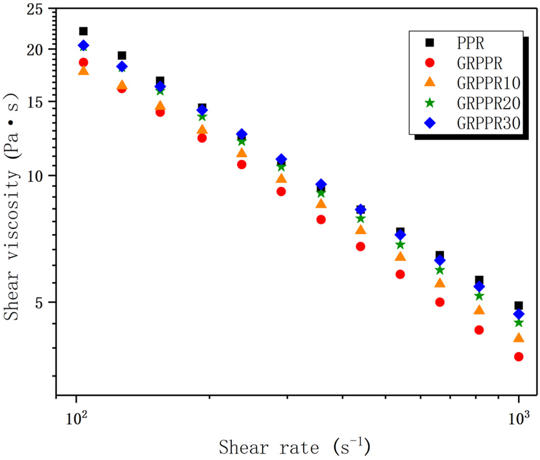
2.3.1. Capillary Rheology Measurements
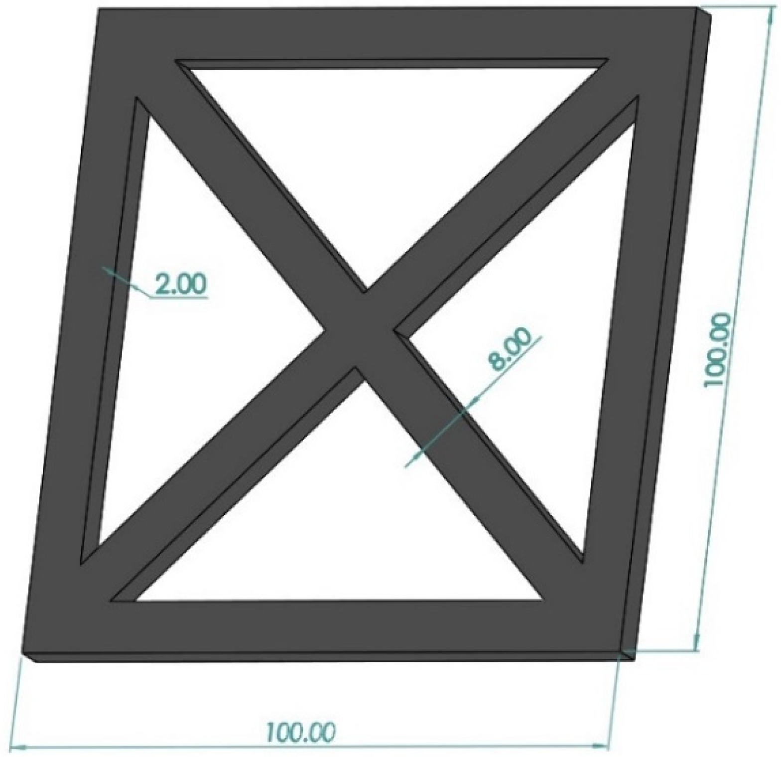
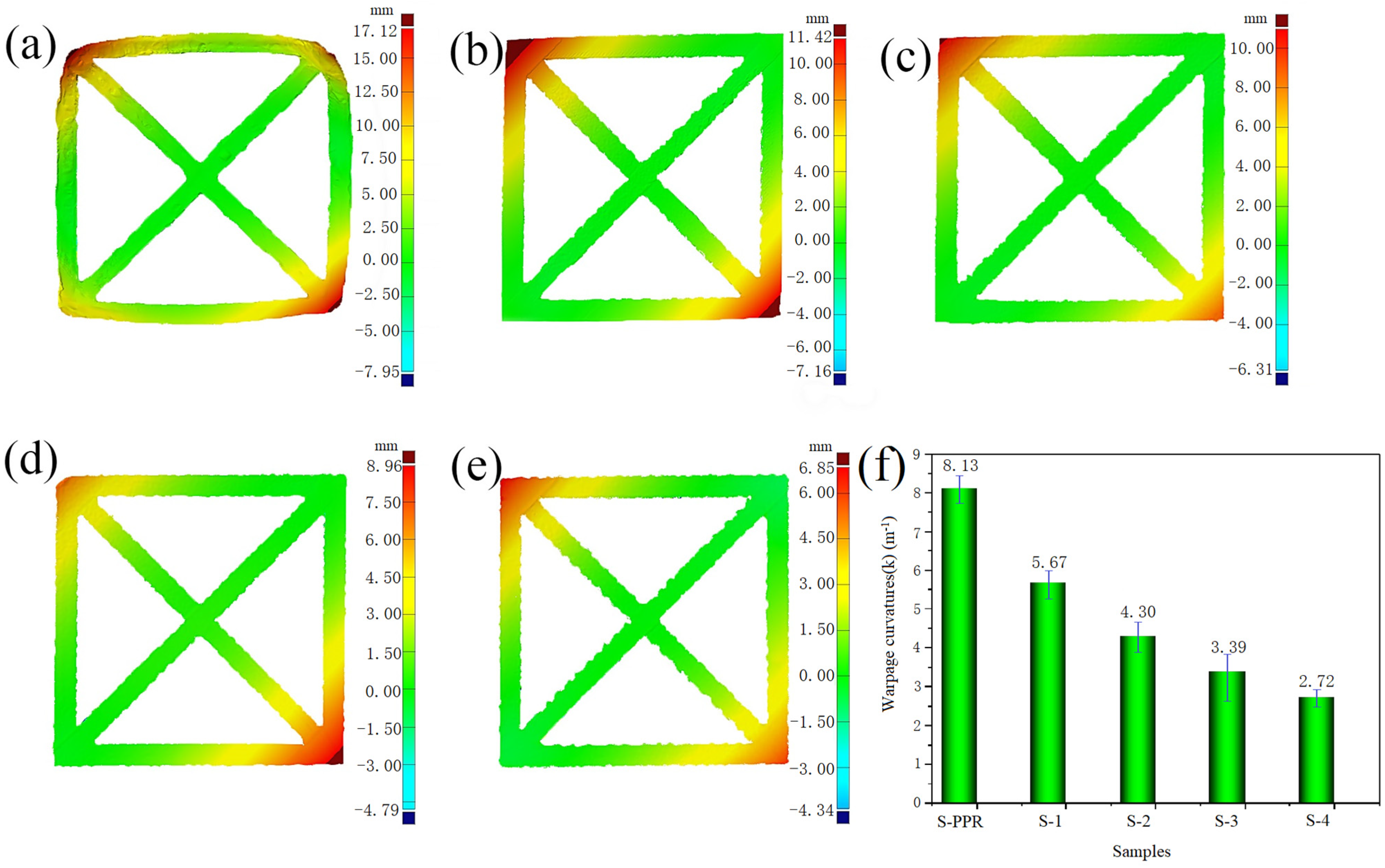
2.3.2. Warpage Analysis
2.3.3. Thermal Tests
2.3.4. Morphological Observation
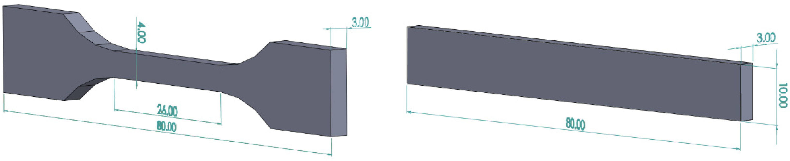
2.3.5. Mechanical Tests
3. Results
3.1. Rheological Properties
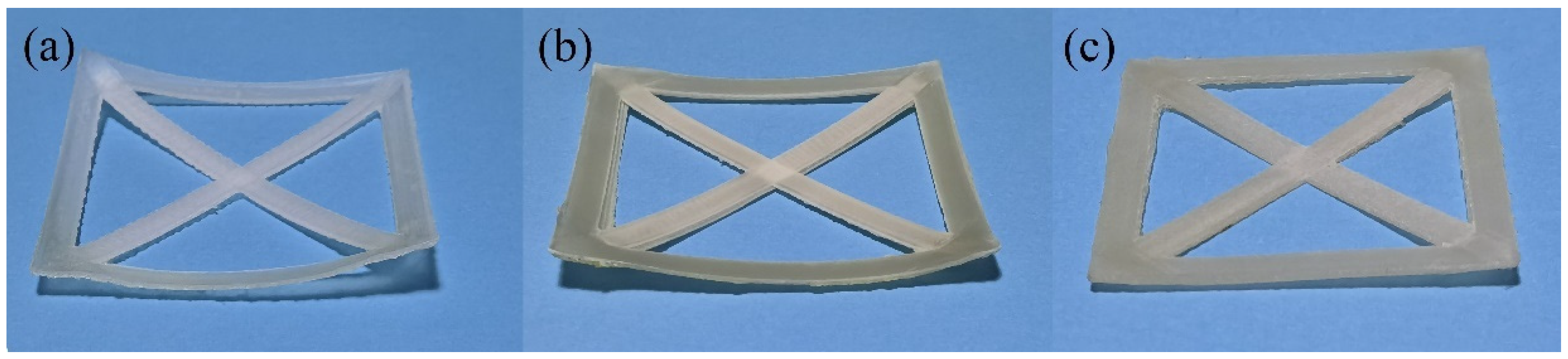
3.2. Warpage Analysis
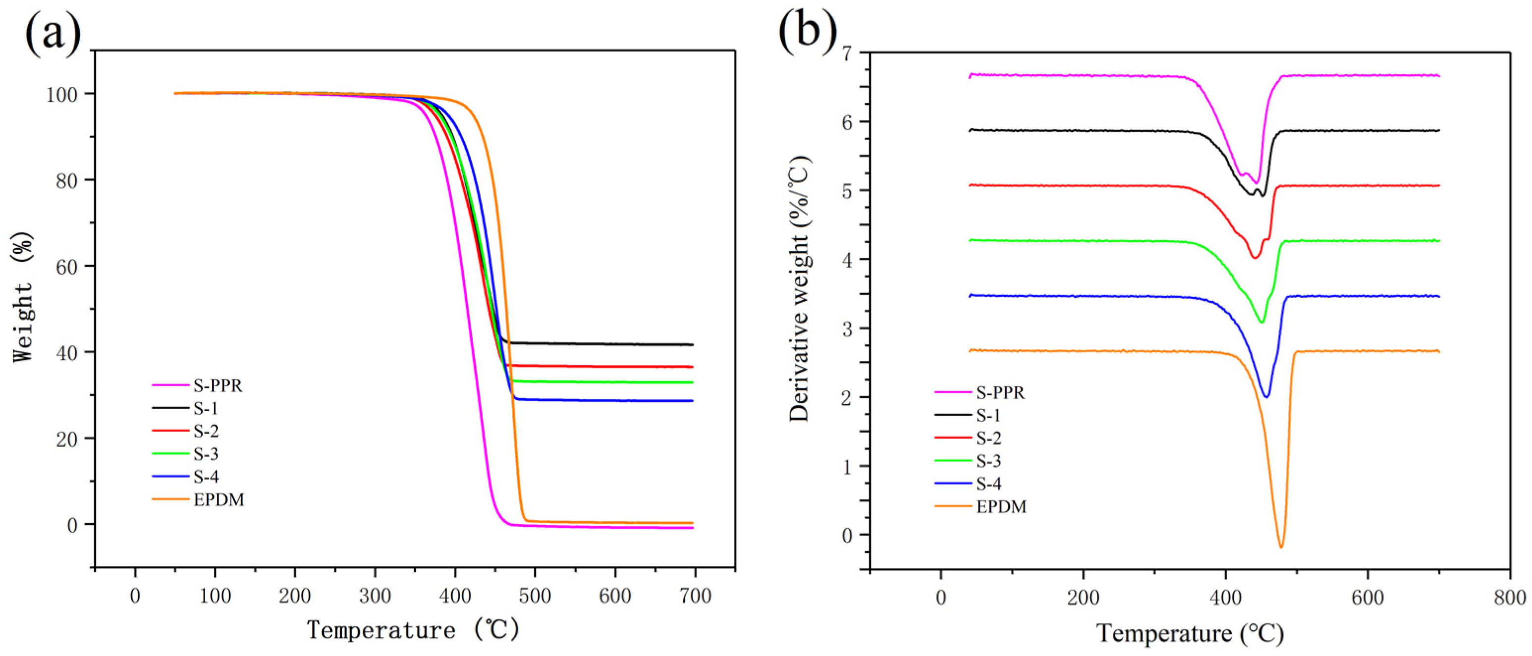
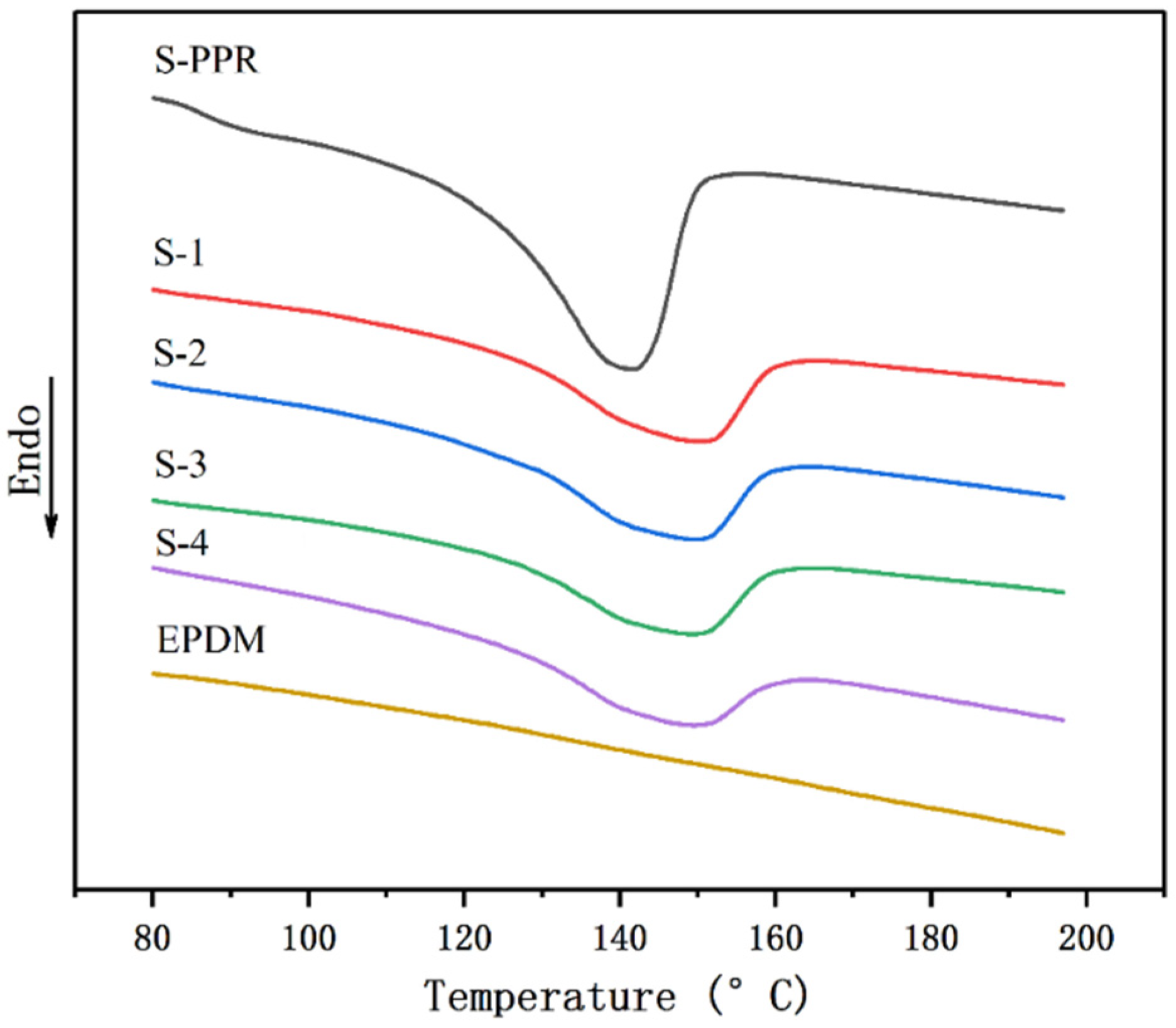
3.3. Thermal Behavior
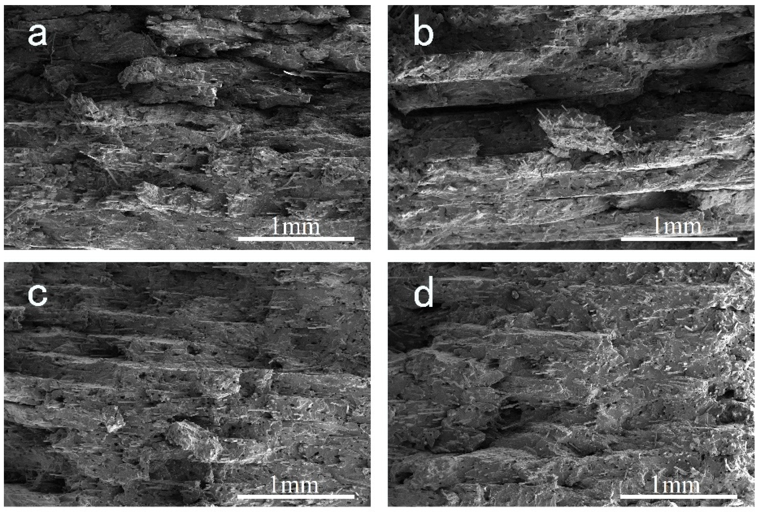
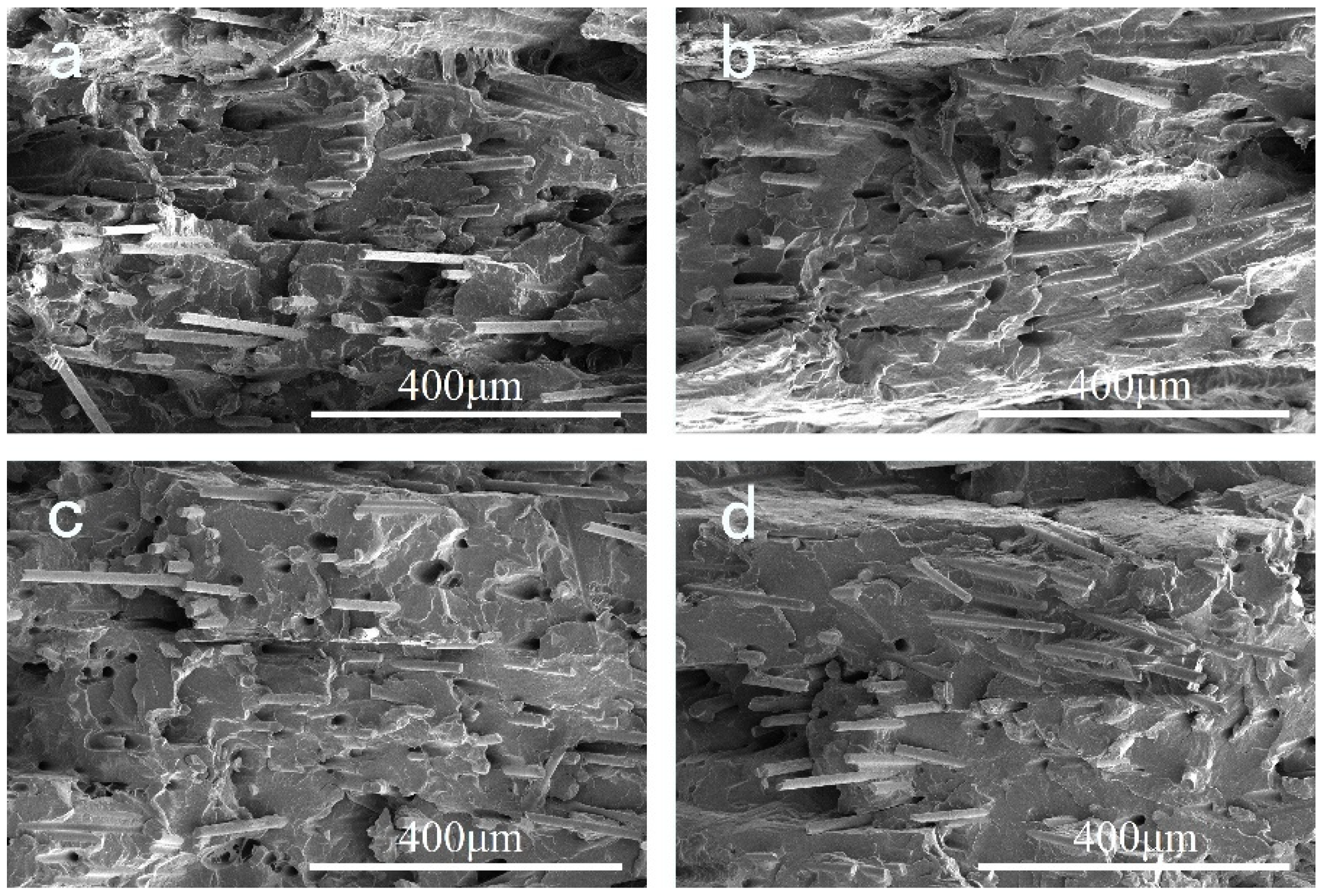
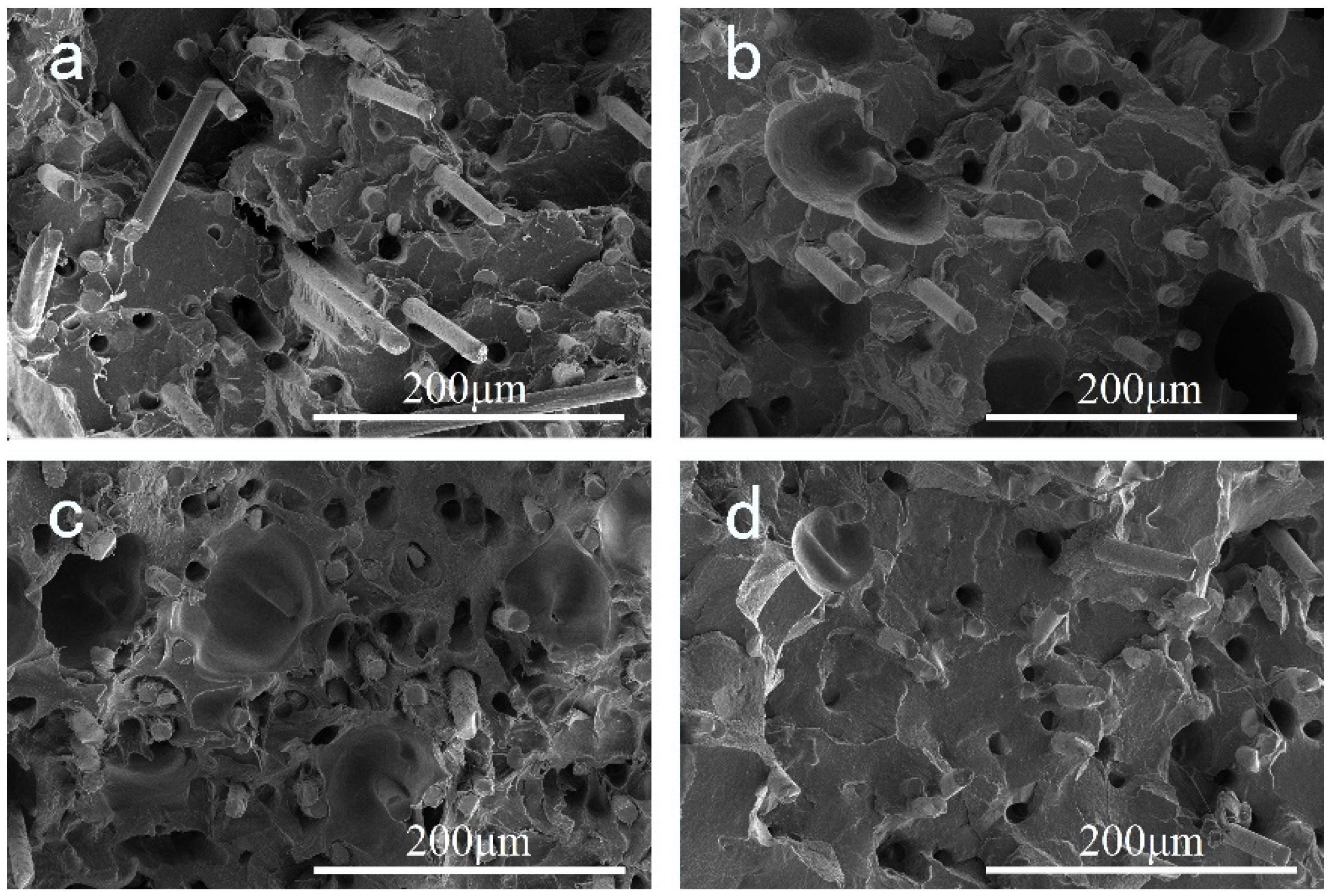
3.4. SEM Observation of Filament
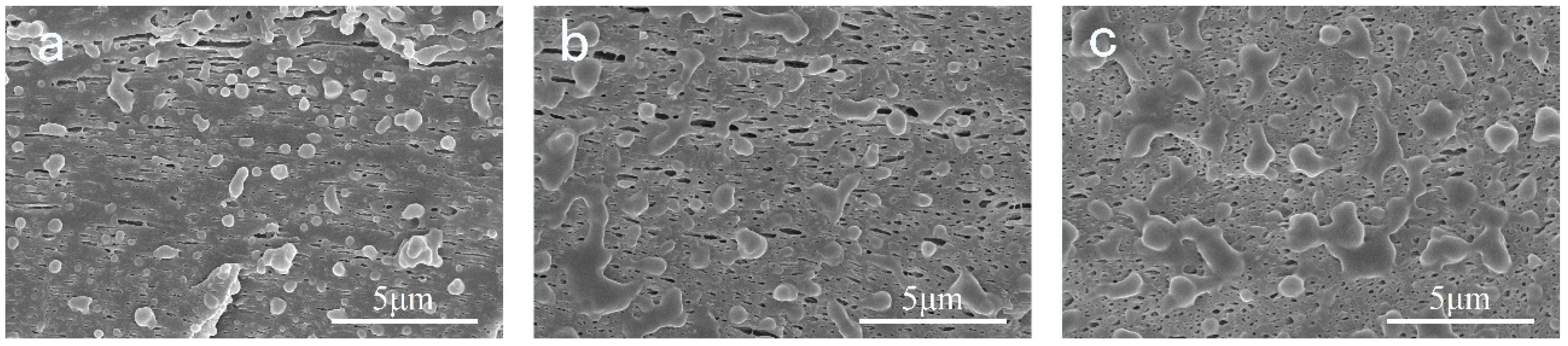
3.5. SEM Observation of Printed Samples
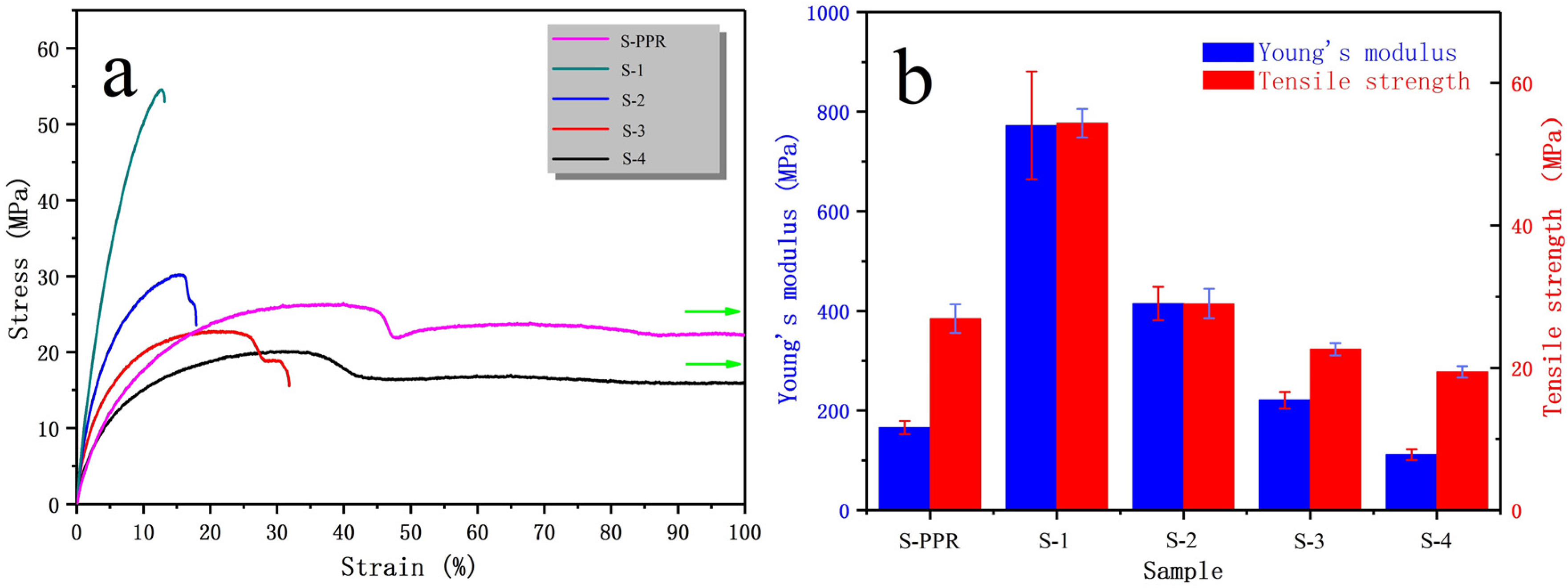
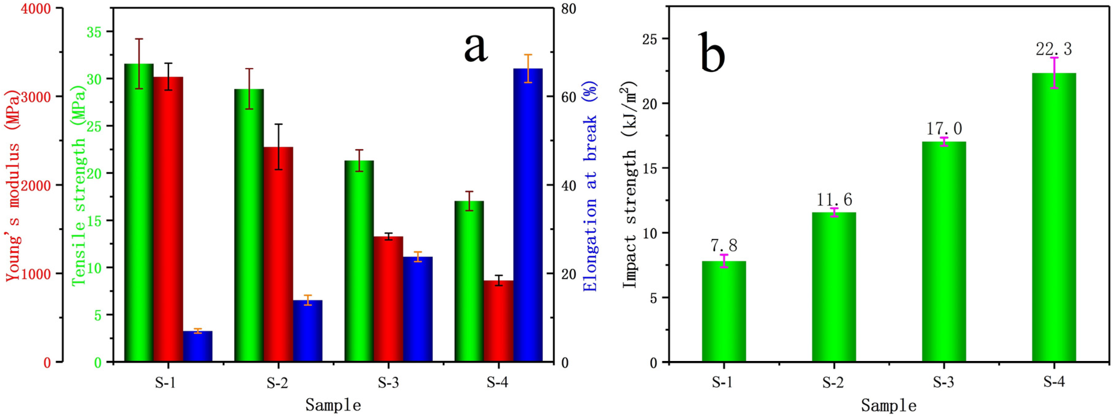
3.6. Mechanical Properties
4. Conclusions
Author Contributions
Funding
Institutional Review Board Statement
Informed Consent Statement
Data Availability Statement
Conflicts of Interest
References
- DebRoy, T.; Wei, H.L.; Zuback, J.S.; Mukherjee, T.; Elmer, J.W.; Milewski, J.O.; Beese, A.M.; Wilson-Heid, A.; De, A.; Zhang, W. Additive manufacturing of metallic components—Process, structure and properties. Prog. Mater. Sci. 2018, 92, 112–224. [Google Scholar] [CrossRef]
- Ngo, T.D.; Kashani, A.; Imbalzano, G.; Nguyen, K.T.Q.; Hui, D. Additive manufacturing (3D printing): A review of materials, methods, applications and challenges. Compos. Part B Eng. 2018, 143, 172–196. [Google Scholar] [CrossRef]
- Levy, G.N.; Schindel, R.; Kruth, J.P. Rapid manufacturing and rapid tooling with layer manufacturing (LM) technologies, state of the art and future perspectives. CIRP Ann. Manuf. Technol. 2003, 52, 589–609. [Google Scholar] [CrossRef]
- Kristiawan, R.B.; Imaduddin, F.; Ariawan, D.; Arifin, Z. A review on the fused deposition modeling (D printing: Filament processing, materials, and printing parameters. Open Eng. 2021, 11, 639–649. [Google Scholar] [CrossRef]
- Vashishtha, V.K.; Makade, R.; Neeraj, M. Advancement of rapid prototyping in aerospace industry—A review. Int. J. Eng. Sci. Technol. 2011, 3, 2486–2493. [Google Scholar]
- Ilardo, R.; Williams, C.B. Design and manufacture of a Formula SAE intake system using fused deposition modeling and fiber-reinforced composite materials. Rapid Prototyp. J. 2010, 16, 174–179. [Google Scholar] [CrossRef]
- Gao, T.; Yang, Z.; Chen, C.; Li, Y.; Fu, K.; Dai, J.; Hitz, E.M.; Xie, H.; Liu, B.; Song, J.; et al. Three-Dimensional Printed Thermal Regulation Textiles. ACS Nano 2017, 11, 11513–11520. [Google Scholar] [CrossRef] [PubMed]
- Upcraft, S.; Fletcher, R. The rapid prototyping technologies. Assem. Autom. 2003, 23, 318–330. [Google Scholar] [CrossRef]
- Pham, D.T.; Gault, R.S. A comparison of rapid prototyping technologies. Int. J. Mach. Tools Manuf. 1998, 38, 1257–1287. [Google Scholar] [CrossRef]
- Nannan, G.; Leu, M.C. Additive manufacturing: Technology, applications and research needs. Front. Mech. Eng. 2013, 8, 215–243. [Google Scholar]
- Wu, J.; Xu, X.; Zhao, Z.; Wang, M.; Zhang, J. Study in performance and morphology of polyamide 12 produced by selective laser sintering technology. Rapid Prototyp. J. 2018, 24, 813–820. [Google Scholar] [CrossRef]
- Dave, H.K.; Patadiya, N.H.; Prajapati, A.R.; Rajpurohit, S.R. Effect of infill pattern and infill density at varying part orientation on tensile properties of fused deposition modeling-printed poly-lactic acid part. Proc. Inst. Mech. Eng. Part C J. Mech. Eng. Sci. 2021, 235, 1811–1827. [Google Scholar] [CrossRef]
- Wang, X.; Jiang, M.; Zhou, Z.W.; Gou, J.H.; Hui, D. 3D printing of polymer matrix composites: A review and prospective. Compos. Part B Eng. 2017, 110, 442–458. [Google Scholar] [CrossRef]
- Valino, A.D.; Dizon, J.R.C.; Espera, A.H., Jr.; Chen, Q.; Messman, J.; Advincula, R.C. Advances in 3D printing of thermoplastic polymer composites and nanocomposites. Prog. Polym. Sci. 2019, 98, 101162. [Google Scholar] [CrossRef]
- Leng, J.; Gu, X.; Hong, R.; Zhang, J. Tailored crystalline structure and enhanced impact strength of isotactic polypropylene/high-density polyethylene blend by controlling the printing speed of fused filament fabrication. J. Mater. Sci. 2020, 55, 14058–14073. [Google Scholar] [CrossRef]
- Skowyra, J.; Pietrzak, K.; Alhnan, M.A. Fabrication of extended-release patient-tailored prednisolone tablets via fused deposition modelling (FDM) 3D printing. Eur. J. Pharm. Sci. 2015, 68, 11–17. [Google Scholar] [CrossRef] [PubMed]
- Sun, Q.; Rizvi, G.M.; Bellehumeur, C.T.; Gu, P. Effect of processing conditions on the bonding quality of FDM polymer filaments. Rapid Prototyp. J. 2008, 14, 72–80. [Google Scholar] [CrossRef]
- Melnikova, R.; Ehrmann, A.; Finsterbusch, K. 3D printing of textile-based structures by Fused Deposition Modelling (FDM) with different polymer materials. IOP Conf. Ser. Mater. Sci. Eng. 2014, 62, 012018. [Google Scholar] [CrossRef] [Green Version]
- Vidakis, N.; Petousis, M.; Tzounis, L.; Maniadi, A.; Velidakis, E.; Mountakis, N.; Papageorgiou, D.; Liebscher, M.; Mechtcherine, V. Sustainable Additive Manufacturing: Mechanical Response of Polypropylene over Multiple Recycling Processes. Sustainability 2021, 13, 159. [Google Scholar] [CrossRef]
- Banerjee, S.S.; Burbine, S.; Shivaprakash, N.K.; Mead, J. 3D-Printable PP/SEBS Thermoplastic Elastomeric Blends: Preparation and Properties. Polymers 2019, 11, 347. [Google Scholar] [CrossRef] [Green Version]
- Spoerk, M.; Holzer, C.; Gonzalez-Gutierrez, J. Material extrusion-based additive manufacturing of polypropylene: A review on how to improve dimensional inaccuracy and warpage. J. Appl. Polym. Sci. 2020, 137, 48545. [Google Scholar] [CrossRef]
- Chatham, C.A.; Zawaski, C.E.; Bobbitt, D.C.; Moore, R.B.; Long, T.E.; Williams, C.B. Semi-crystalline polymer blends for material extrusion additive manufacturing printability: A case study with poly(ethylene terephthalate) and polypropylene. Macromol. Mater. Eng. 2019, 304, 1800764. [Google Scholar] [CrossRef]
- Varga, J.; KargerKocsis, J. Rules of supermolecular structure formation in sheared isotactic polypropylene melts. J. Polym. Sci. Part B Polym. Phys. 1996, 34, 657–670. [Google Scholar] [CrossRef]
- Mi, D.; Xia, C.; Jin, M.; Wang, F.; Shen, K.; Zhang, J. Quantification of the effect of Shish-Kebab structure on the mechanical properties of polypropylene samples by controlling shear layer thickness. Macromolecules 2016, 49, 4571–4578. [Google Scholar] [CrossRef]
- Carneiro, O.S.; Silva, A.F.; Silva, A.F. Fused deposition modeling with polypropylene. Mater. Des. 2015, 83, 768–776. [Google Scholar] [CrossRef]
- Sodeifian, G.; Ghaseminejad, S.; Yousefi, A.A. Preparation of polypropylene/short glass fiber composite as Fused Deposition Modeling (FDM) filament. Results Phys. 2019, 12, 205–222. [Google Scholar] [CrossRef]
- Spoerk, M.; Sapkota, J.; Weingrill, G.; Fischinger, T.; Arbeiter, F.; Holzer, C. Shrinkage and Warpage Optimization of Expanded-Perlite-Filled Polypropylene Composites in Extrusion-Based Additive Manufacturing. Macromol. Mater. Eng. 2017, 302, 1700143. [Google Scholar] [CrossRef]
- Bachhar, N.; Gudadhe, A.; Kumar, A.; Andrade, P.; Kumaraswamy, G. 3D printing of semicrystalline polypropylene: Towards eliminating warpage of printed objects. Bull. Mater. Sci. 2020, 43, 171. [Google Scholar] [CrossRef]
- Pasquini, N.; Addeo, A. Polypropylene Handbook; Hanser Verlag: Munich, Germany, 2005. [Google Scholar]
- Deng, C.; Jin, B.; Zhao, Z.; Shen, K.; Zhang, J. The influence of hoop shear field on the structure and performances of glass fiber reinforced three-layer polypropylene random copolymer pipe. J. Appl. Polym. Sci. 2019, 136, 46985. [Google Scholar] [CrossRef]
- Gahleitner, M.; Jaaskelainen, P.; Ratajski, E.; Paulik, C.; Reussner, J.; Wolfschwenger, J.; Neissl, W. Propylene–ethylene random copolymers: Comonomer effects on crystallinity and application properties. J. Appl. Polym. Sci. 2010, 95, 1073–1081. [Google Scholar] [CrossRef]
- Gu, X.; Wang, Y.; Jiang, Y.; Liu, M.; Fu, Q.; Zhang, J. High impact performance induced by a synergistic effect of heteroepitaxy and oriented layer-unoriented layer alternated structure in iPP/HDPE injection molded part. Polymer 2019, 175, 206–214. [Google Scholar] [CrossRef]
- Li, J.Q.; Leng, J.; Jiang, Y.X.; Zhang, J. Experimental characterization of 3D printed PP/h-BN thermally conductive composites with highly oriented h-BN and the effects of filler size. Compos. Part A Appl. Sci. Manuf. 2021, 150, 106586. [Google Scholar] [CrossRef]
- Calafel, I.; Aguirresarobe, R.H.; Penas, M.I.; Santamaria, A.; Tierno, M.; Conde, J.I.; Pascual, B. Searching for Rheological Conditions for FFF 3D Printing with PVC Based Flexible Compounds. Materials 2020, 13, 178. [Google Scholar] [CrossRef] [PubMed] [Green Version]
- Tao, Y.B.; Liu, M.M.; Han, W.J.; Li, P. Waste office paper filled polylactic acid composite filaments for 3D printing. Compos. Part B Eng. 2021, 211, 108998. [Google Scholar] [CrossRef]
- Das, A.; Etemadi, M.; Davis, B.A.; Mcknight, S.H.; Williams, C.B.; Case, S.W.; Bortner, M.J. Rheological investigation of nylon-carbon fiber composites fabricated using material extrusion-based additive manufacturing. Polym. Compos. 2021, 42, 6010–6024. [Google Scholar] [CrossRef]
- Fu, T.F.; Zhang, Y.; Zhang, J.; Wang, T.; Gao, X.Q. Suppression of the Skin-Core Structure of Injection-Molded Polypropylene Part: Role of Balance Effect Caused by the Incorporation of Glass Fiber. J. Macromol. Sci. Part B Phys. 2014, 53, 861–877. [Google Scholar] [CrossRef]
- Gupta, A.K.; Kumar, P.K.; Ratnam, B.K. Glass-Fiber-Reinforced Polypropylene EPDM blend.1. Melt Rheological Properties. J. Appl. Polym. Sci. 1991, 42, 2595–2611. [Google Scholar] [CrossRef]
- Ryu, Y.; Sohn, J.S.; Kweon, B.C.; Cha, S.W. Shrinkage Optimization in Talc- and Glass-Fiber-Reinforced Polypropylene Composites. Materials 2019, 12, 764. [Google Scholar] [CrossRef] [Green Version]
- Jerry, M.F. Handbook of Molded Part Shrinkage and Warpage; William Andrew Publishing: New York, NY, USA, 2003. [Google Scholar]
- Chatterjee, A.; Deopura, B.L. Thermal Stability of Polypropylene/Carbon Nanofiber Composite. J. Appl. Polym. Sci. 2006, 100, 3574–3578. [Google Scholar] [CrossRef]
- Bogoeva-Gaceva, G.; Janevski, A.; Mader, E. Nucleation activity of glass fibers towards iPP evaluated by DSC and polarizing light microscopy. Polymer 2001, 42, 4409–4416. [Google Scholar] [CrossRef]
- Gupta, A.K.; Srinivasan, K.R.; Kumar, P.K. Glass Fiber Reinforced Polypropylene/ EPDM Blends. 11. Mechanical Properties and Morphology. J. Appl. Polym. Sci. 1991, 43, 451–462. [Google Scholar] [CrossRef]
- Etcheverry, M.; Barbosa, S.E. Glass Fiber Reinforced Polypropylene Mechanical Properties Enhancement by Adhesion Improvement. Materials 2012, 5, 1084–1113. [Google Scholar] [CrossRef] [PubMed] [Green Version]
- Pratama, J.; Cahyono, S.I.; Suyitno, S.; Muflikhun, M.A.; Salim, U.A.; Mahardika, M.; Arifvianto, B. A Review on Reinforcement Methods for Polymeric Materials Processed Using Fused Filament Fabrication (FFF). Polymers 2021, 13, 4022. [Google Scholar] [CrossRef] [PubMed]
- Jang, B.Z.; Vandersande, J.B.; Uhlmann, D.R. Crystalline morphology of polypropylene and rubber-modified polypropylene. Abstr. Pap. Am. Chem. Soc. 1983, 186, 142-PMSE. [Google Scholar] [CrossRef]


| Sample Designation | PPR (wt.%) | GF (wt.%) | EPDM (wt.%) |
|---|---|---|---|
| S-PPR | 100 | - | - |
| S-1 | 60 | 40 | - |
| S-2 | 54 | 36 | 10 |
| S-3 | 48 | 32 | 20 |
| S-4 | 42 | 28 | 30 |
| Printing Parameters | Value |
|---|---|
| Nozzle temperature (°C) | 220 |
| Printing bed temperature (°C) | 30 |
| Nozzle diameter (mm) | 0.4 |
| Layer thickness (mm) | 0.2 |
| Printing orientation (°) | ±45 |
| Filling degree (%) | 100 |
| Linear printing speed for the 1st layer (mm/s) | 72 |
| Linear printing speed for the other layers (mm/s) | 80 |
| Contour number | 1 |
| Sample | Initial Degradation Temperature (°C) | Maximum Degradation Rate Temperature (°C) |
|---|---|---|
| S-PPR | 302 | 436 |
| S-1 | 351 | 445 |
| S-2 | 345 | 434 |
| S-3 | 347 | 444 |
| S-4 | 341 | 452 |
| EPDM | 374 | 471 |
| Sample | Tm (°C) | ΔHm (J/g) | Xc (%) |
|---|---|---|---|
| S-PPR | 141.4 | 47.0 | 22.7 |
| S-1 | 149.4 | 28.8 | 23.2 |
| S-2 | 148.6 | 28.0 | 25.0 |
| S-3 | 148.2 | 24.4 | 24.6 |
| S-4 | 148.2 | 24.4 | 24.6 |
| EPDM | -- | -- | -- |
Publisher’s Note: MDPI stays neutral with regard to jurisdictional claims in published maps and institutional affiliations. |
© 2022 by the authors. Licensee MDPI, Basel, Switzerland. This article is an open access article distributed under the terms and conditions of the Creative Commons Attribution (CC BY) license (https://creativecommons.org/licenses/by/4.0/).
Share and Cite
Zhang, Z.; Gao, X. Polypropylene Random Copolymer Based Composite Used for Fused Filament Fabrication: Printability and Properties. Polymers 2022, 14, 1106. https://doi.org/10.3390/polym14061106
Zhang Z, Gao X. Polypropylene Random Copolymer Based Composite Used for Fused Filament Fabrication: Printability and Properties. Polymers. 2022; 14(6):1106. https://doi.org/10.3390/polym14061106
Chicago/Turabian StyleZhang, Zhiyao, and Xueqin Gao. 2022. "Polypropylene Random Copolymer Based Composite Used for Fused Filament Fabrication: Printability and Properties" Polymers 14, no. 6: 1106. https://doi.org/10.3390/polym14061106
APA StyleZhang, Z., & Gao, X. (2022). Polypropylene Random Copolymer Based Composite Used for Fused Filament Fabrication: Printability and Properties. Polymers, 14(6), 1106. https://doi.org/10.3390/polym14061106