

Effect of Heat Treatment on Elastic Properties and Fracture Toughness of Fused Filament Fabricated PEEK for Biomedical Applications


Abstract
1. Introduction
2. Methods
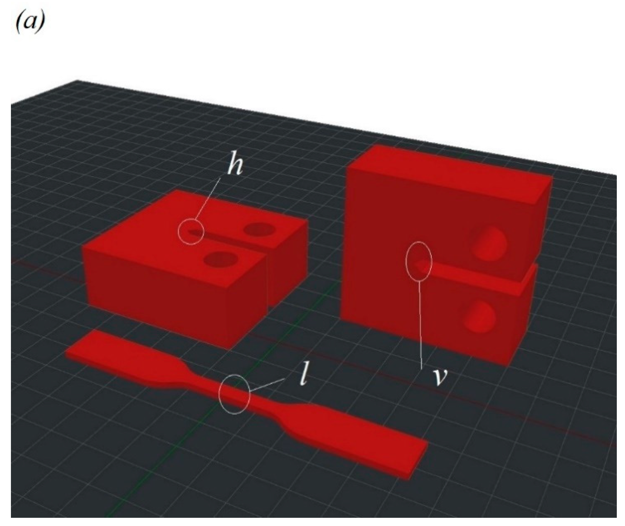
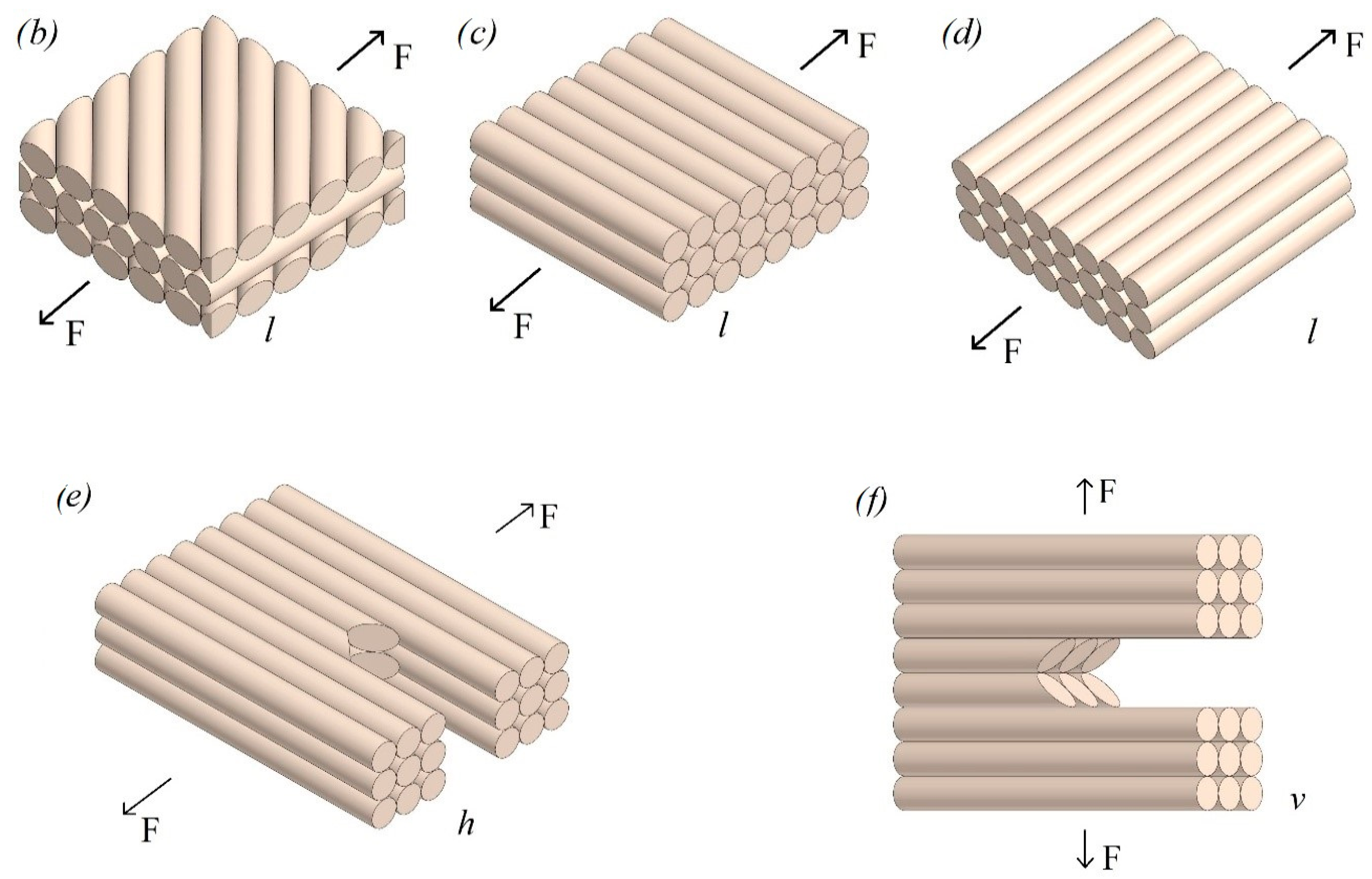
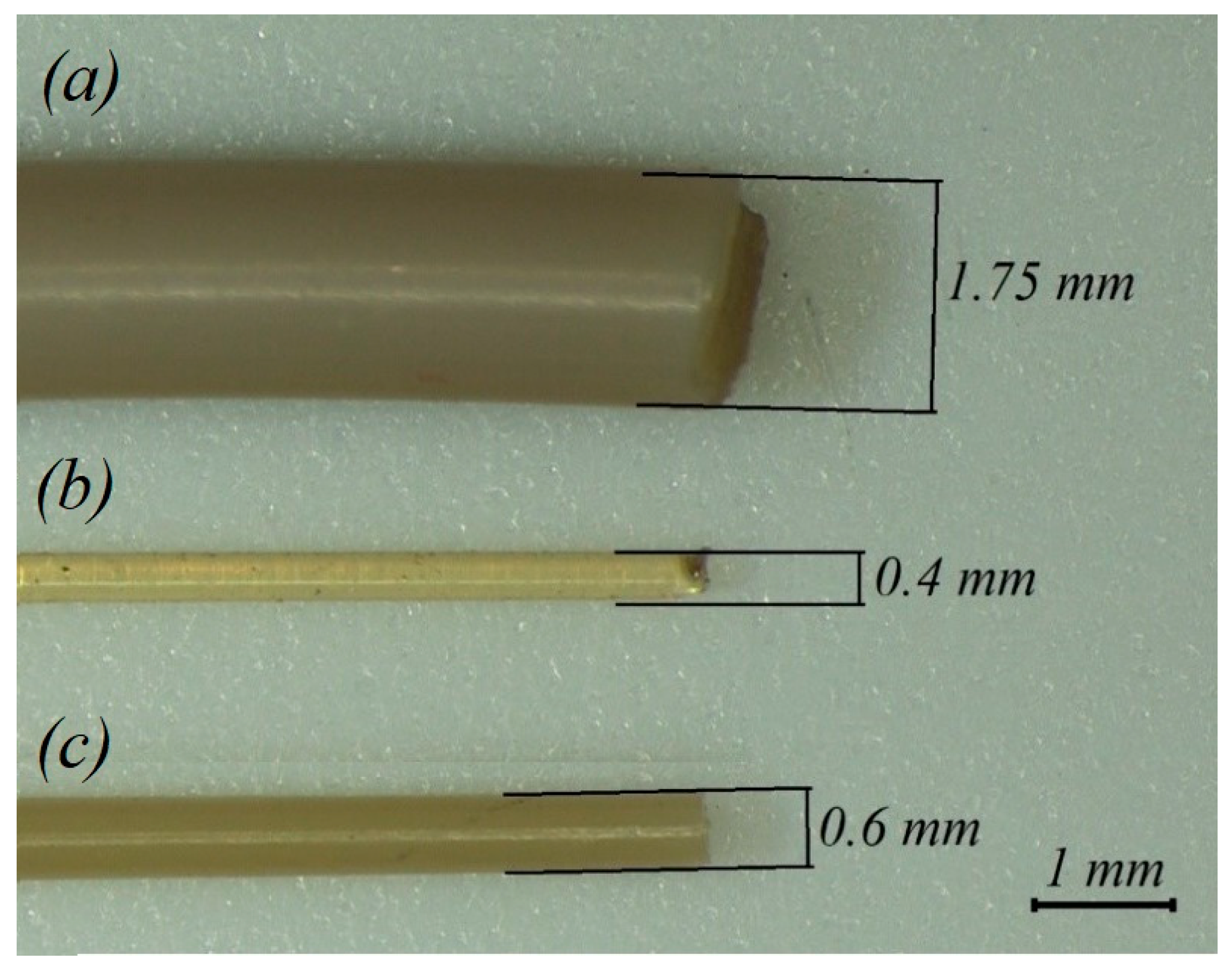
2.1. Manufacturing of Samples
2.2. Tensile Testing
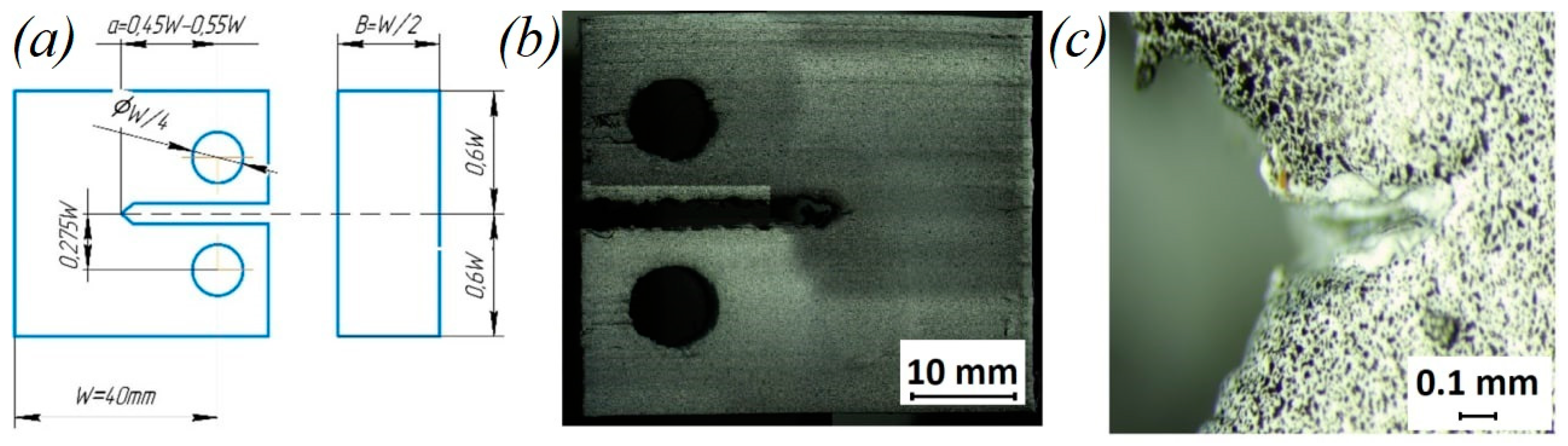
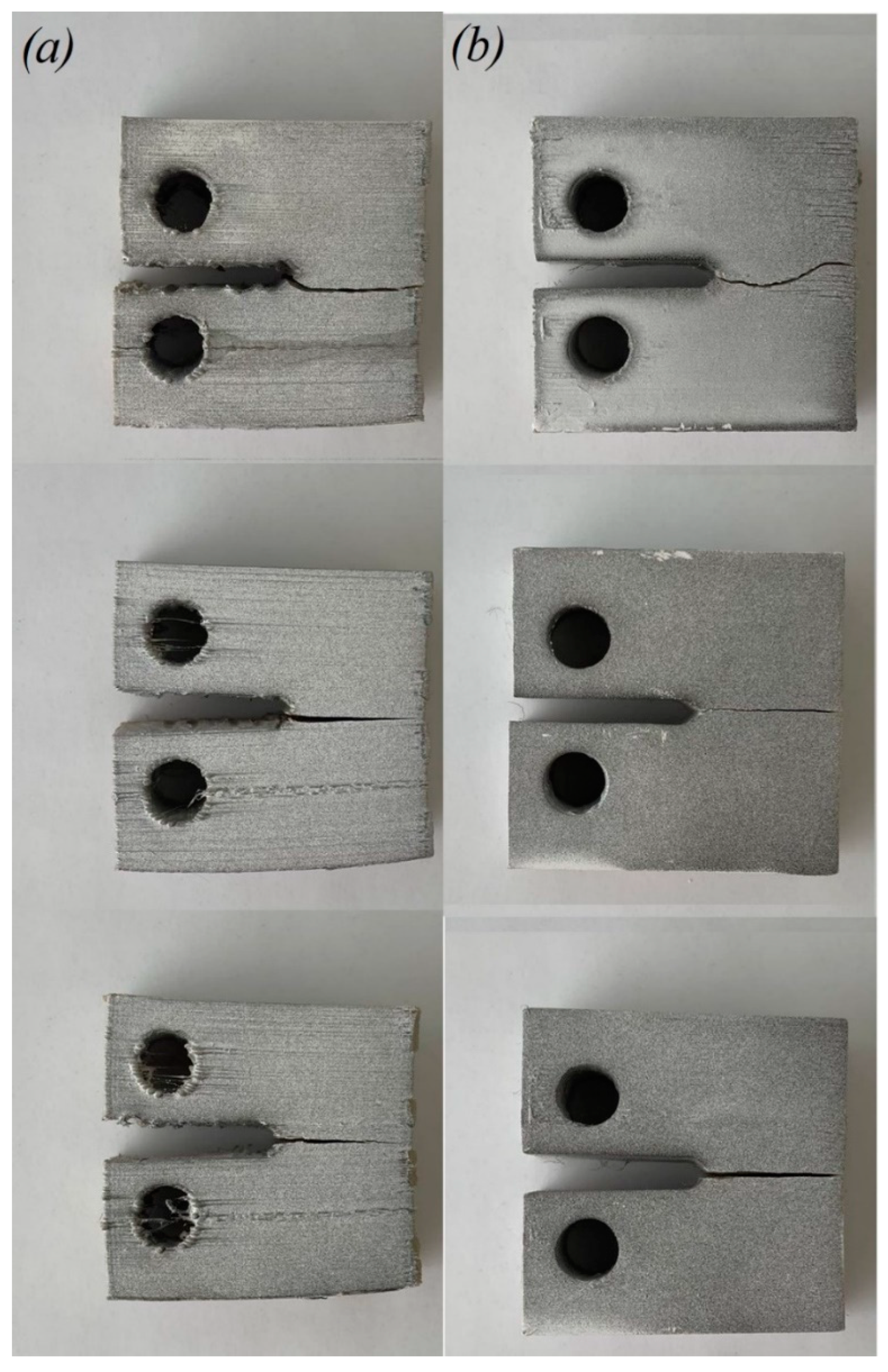
2.3. Fracture Tests
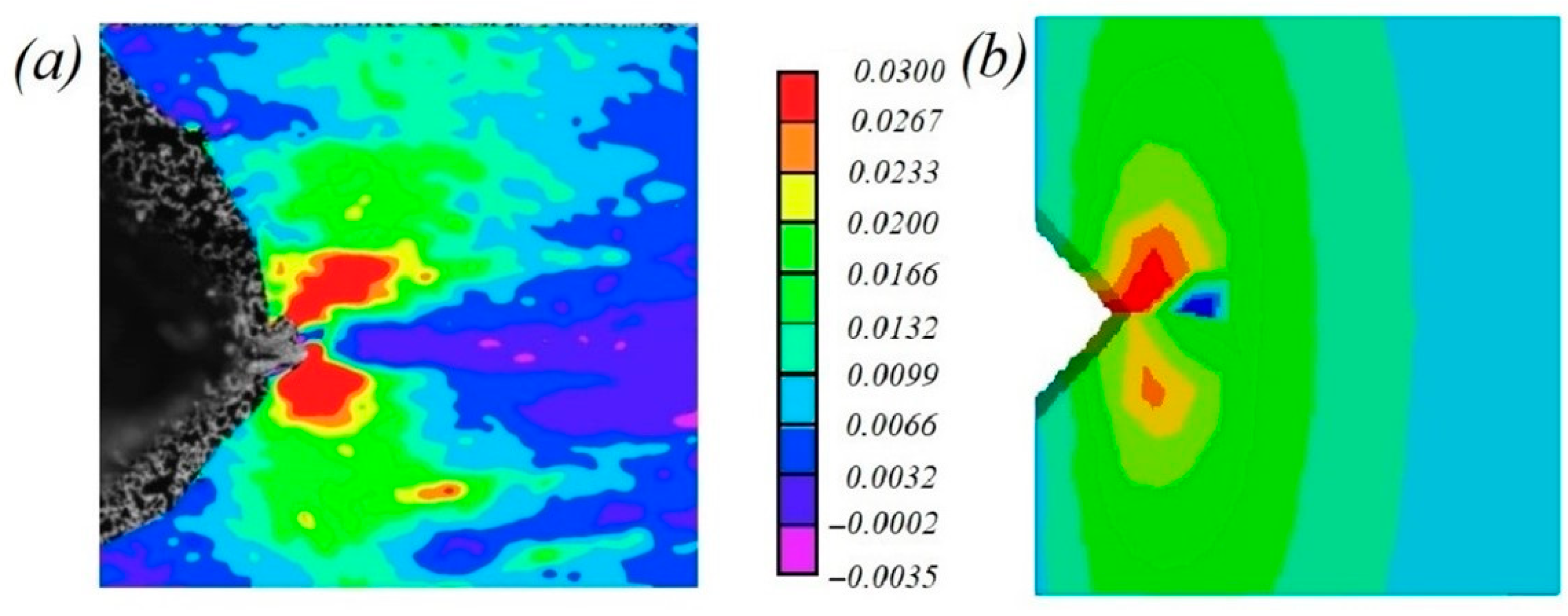
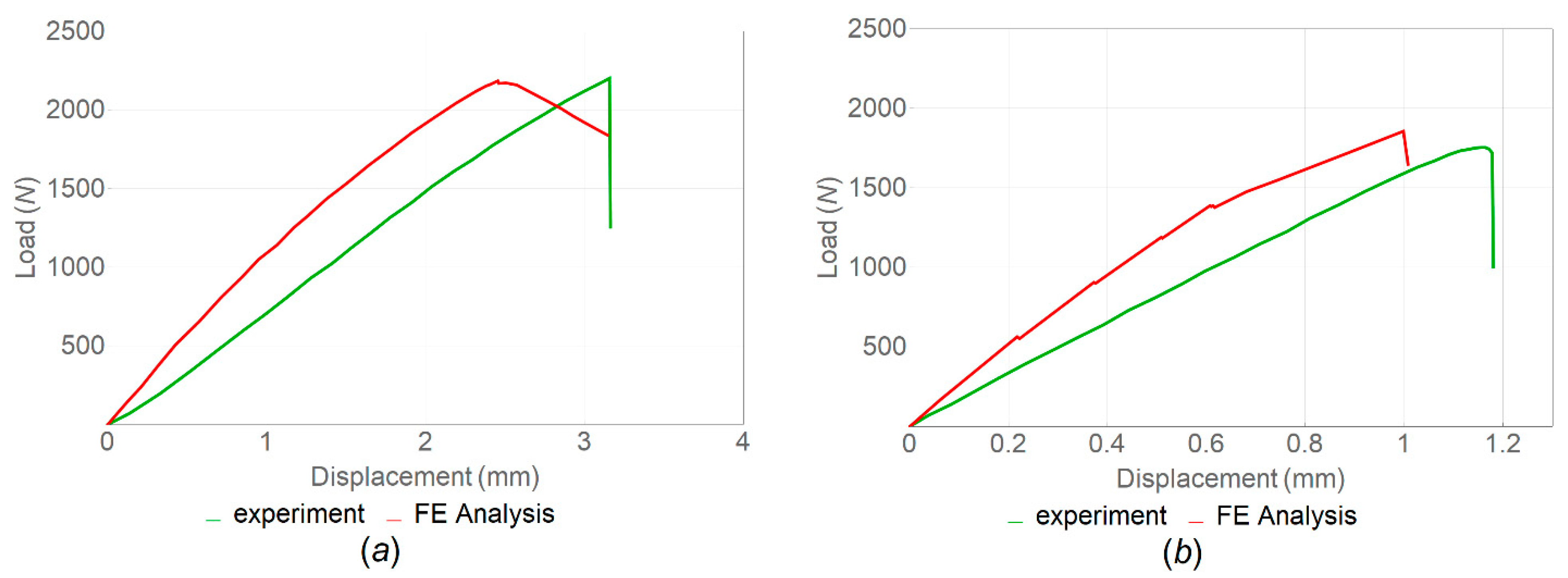
2.4. Numerical Calculations
3. Results and Discussion
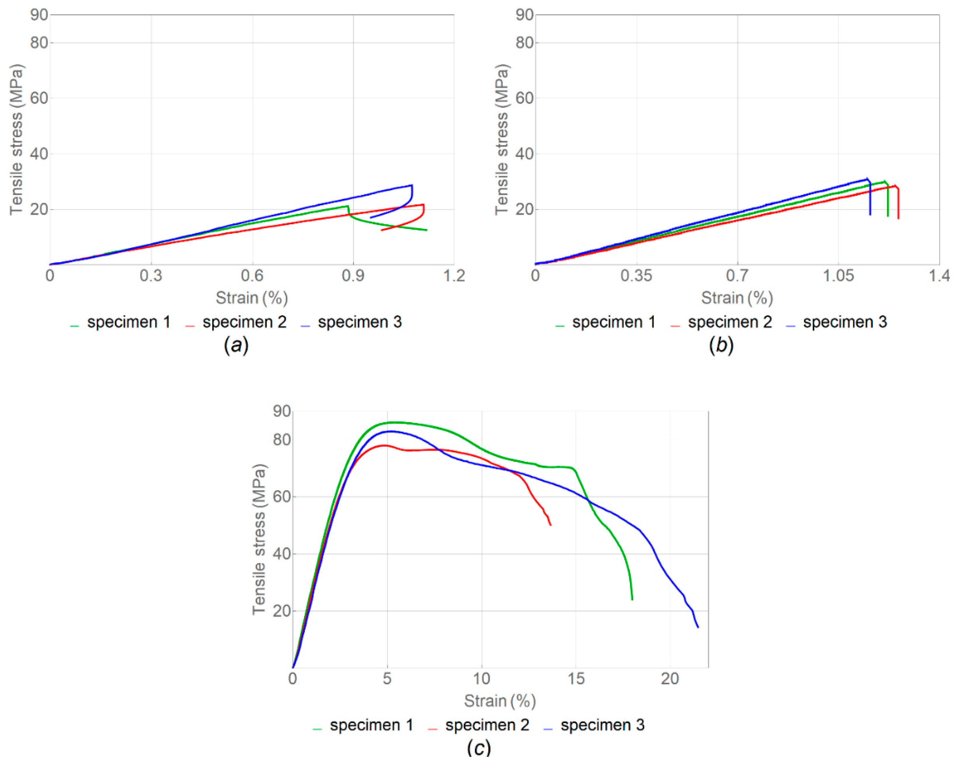
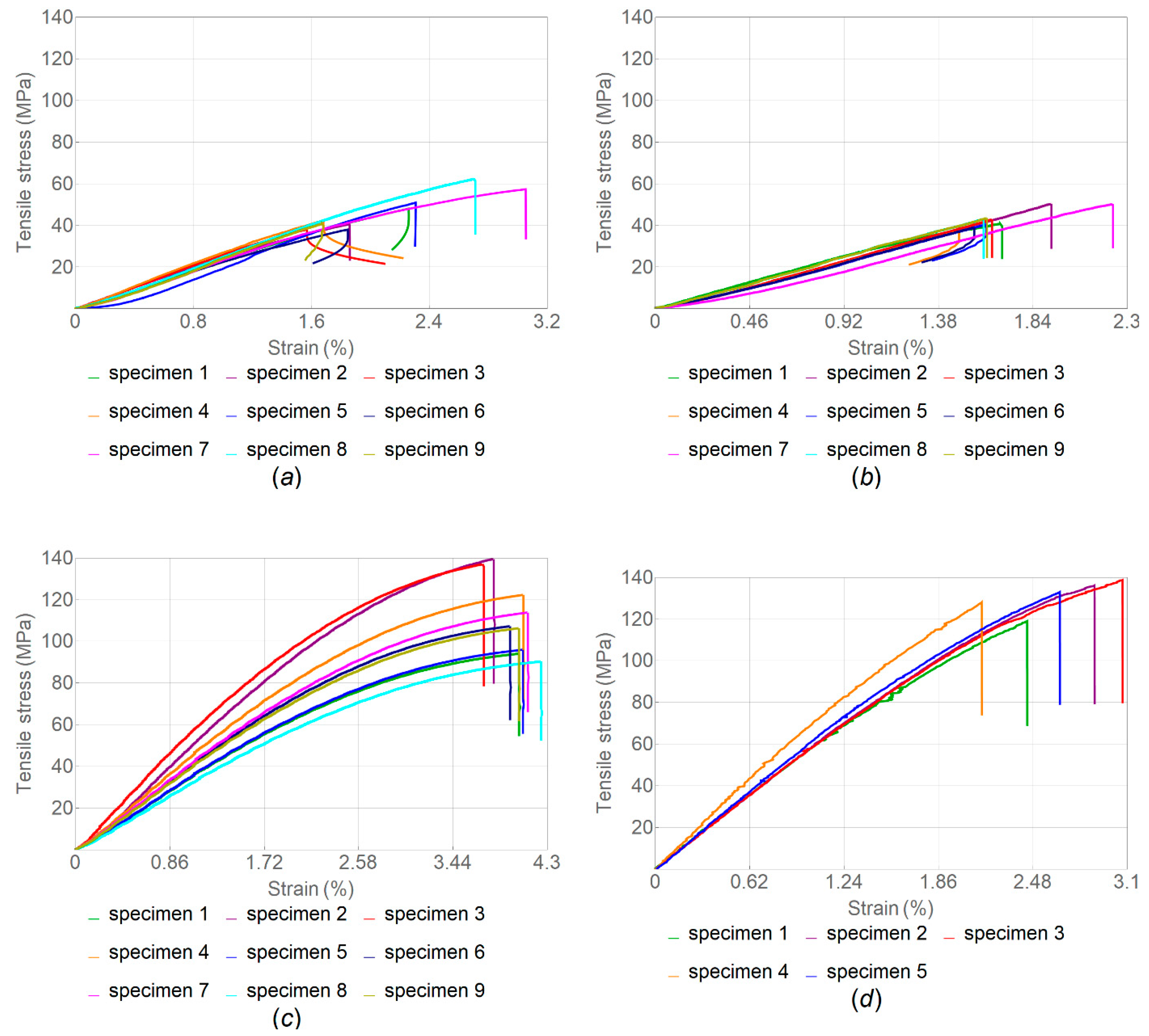
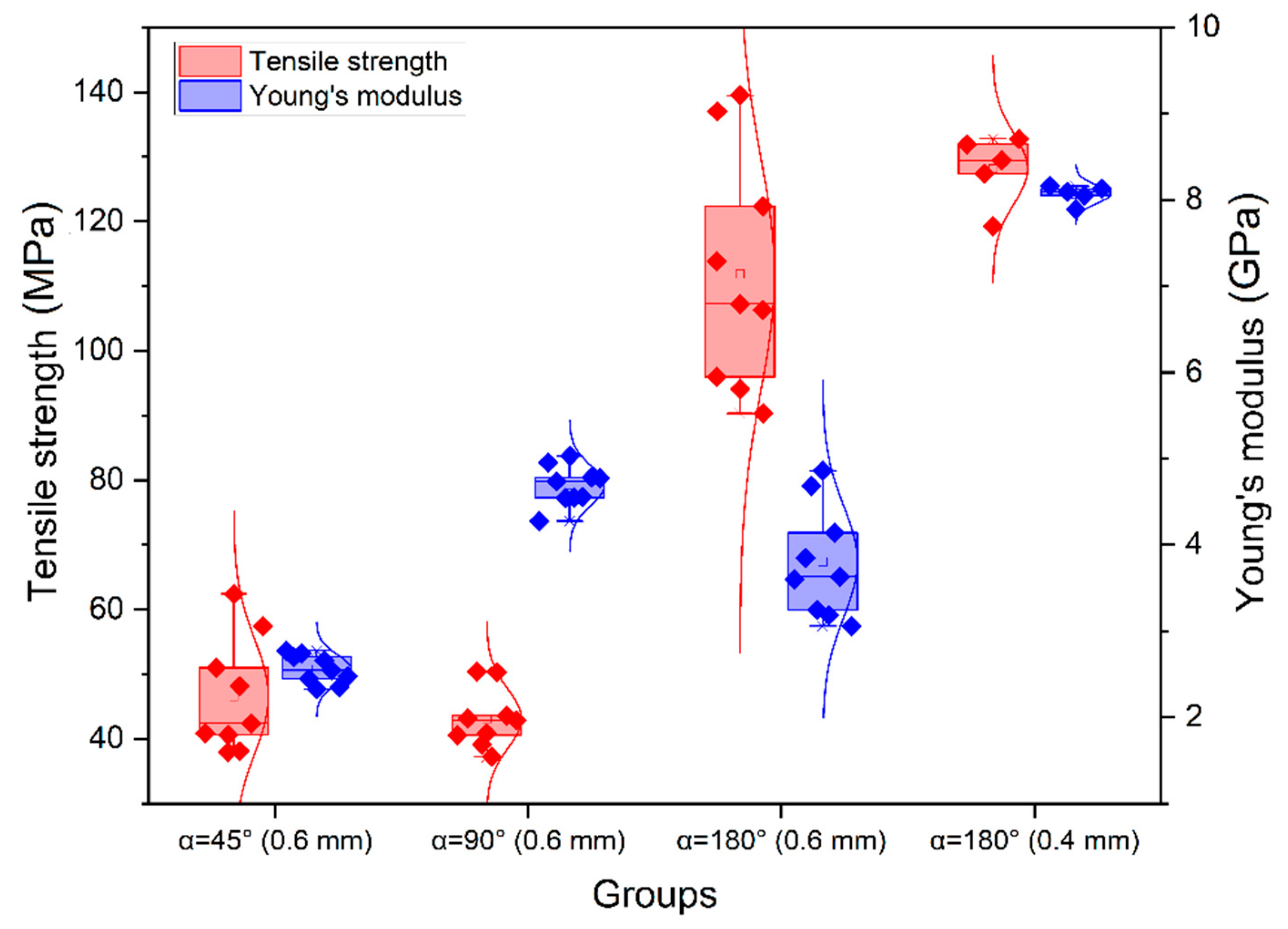
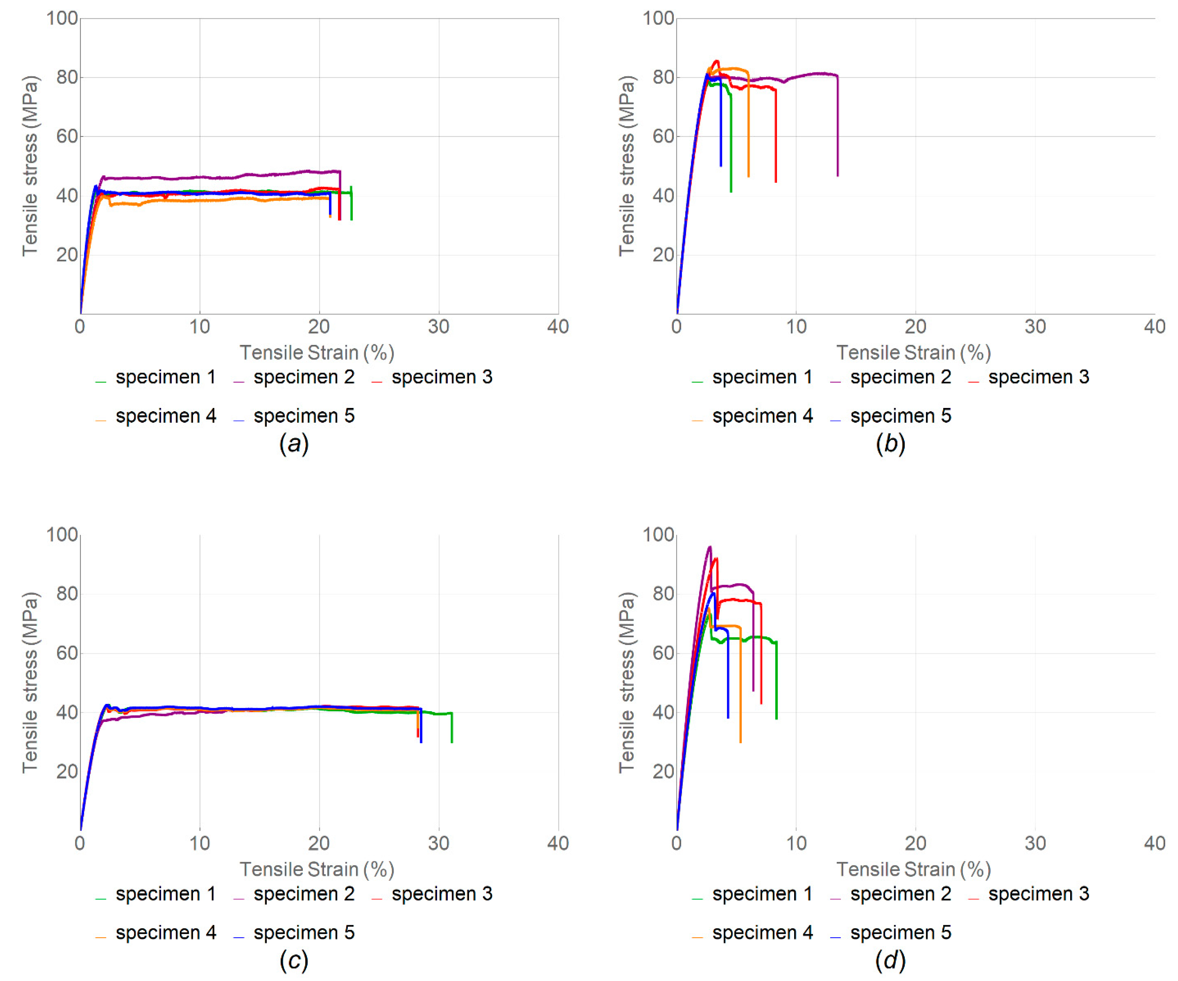
3.1. Effect of Filament Infill Angle on Tensile Properties
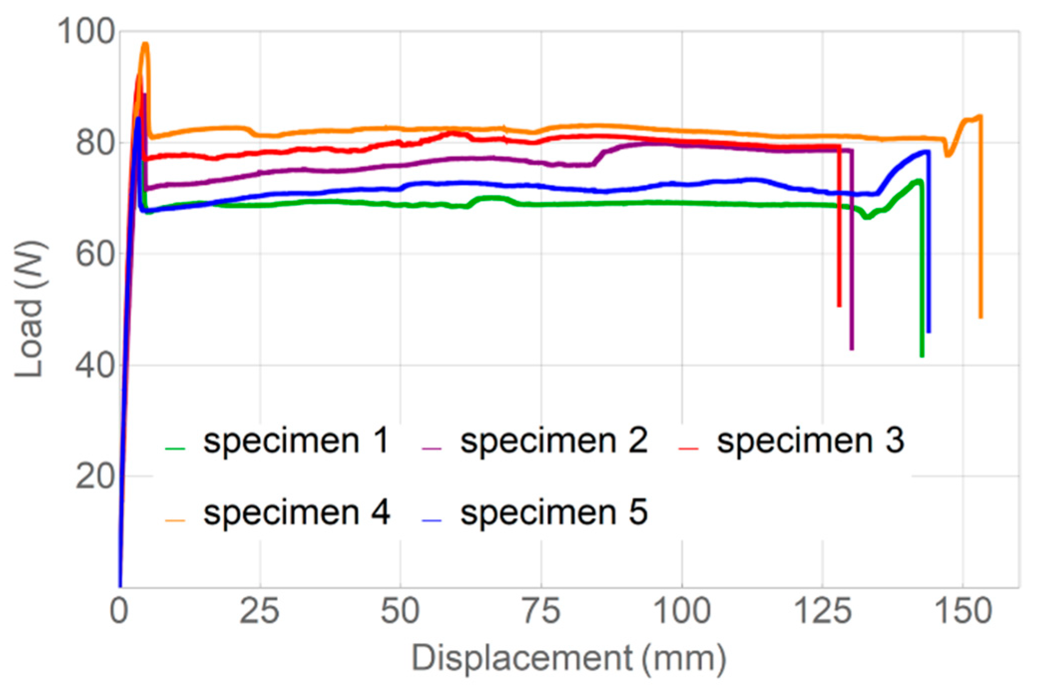
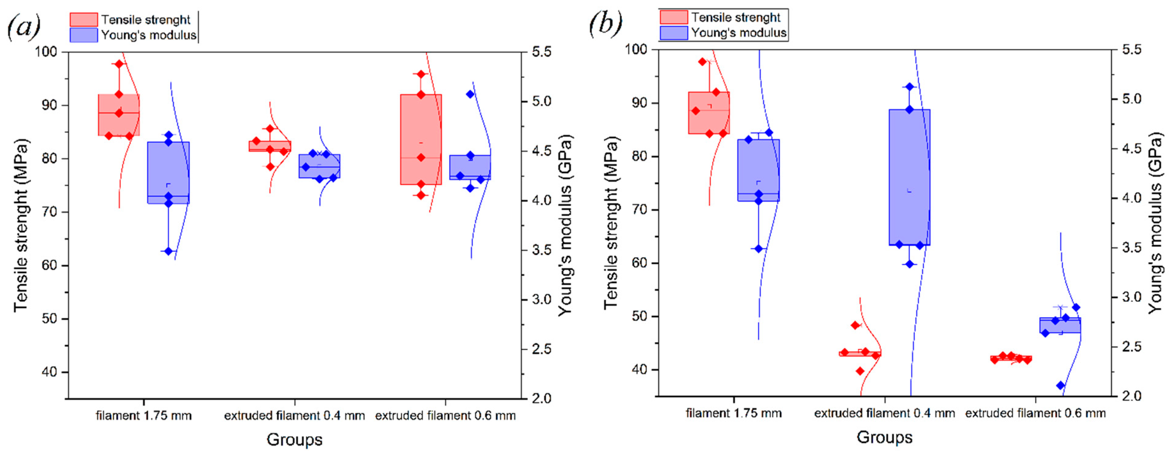
3.2. Investigation of Filament Properties
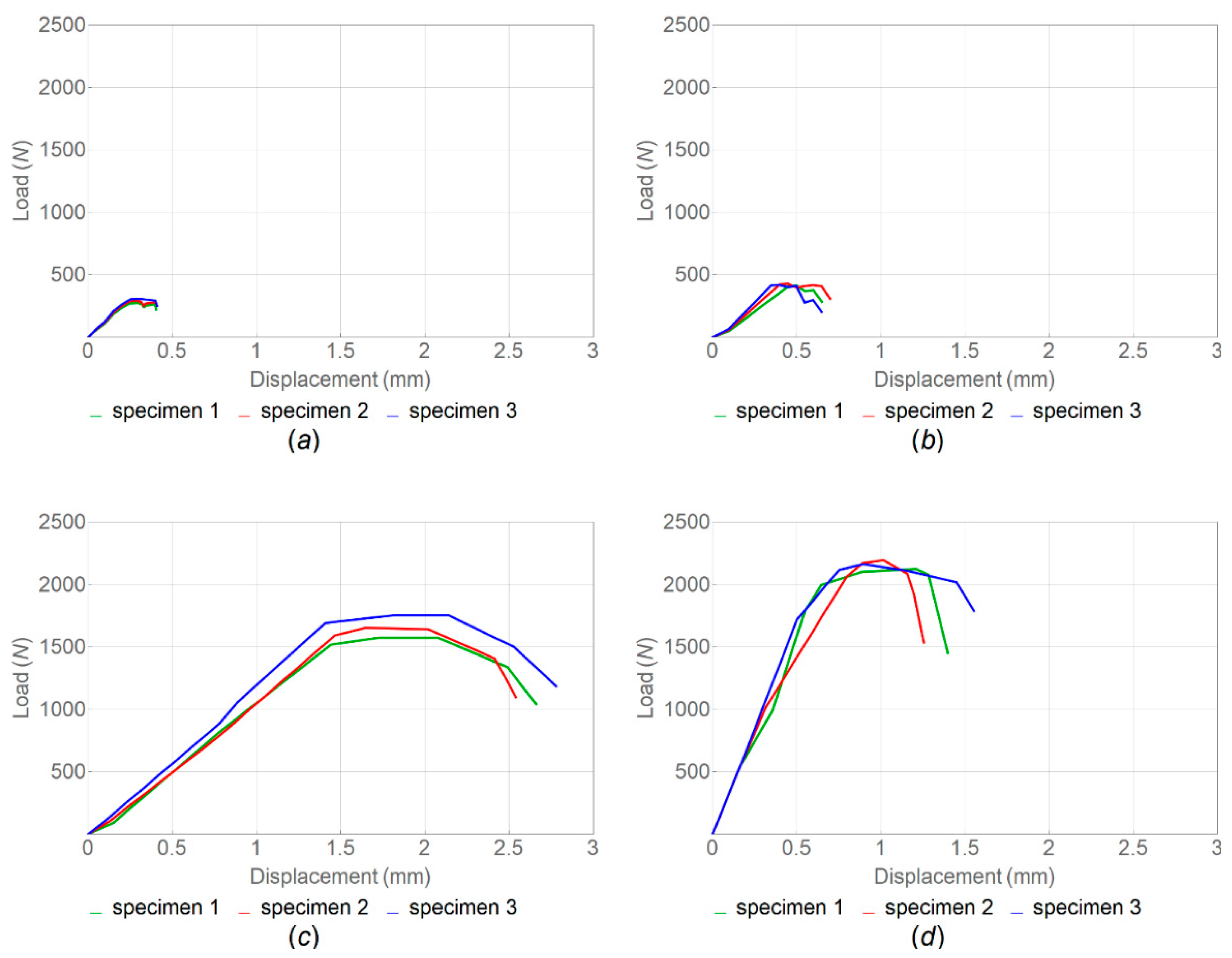
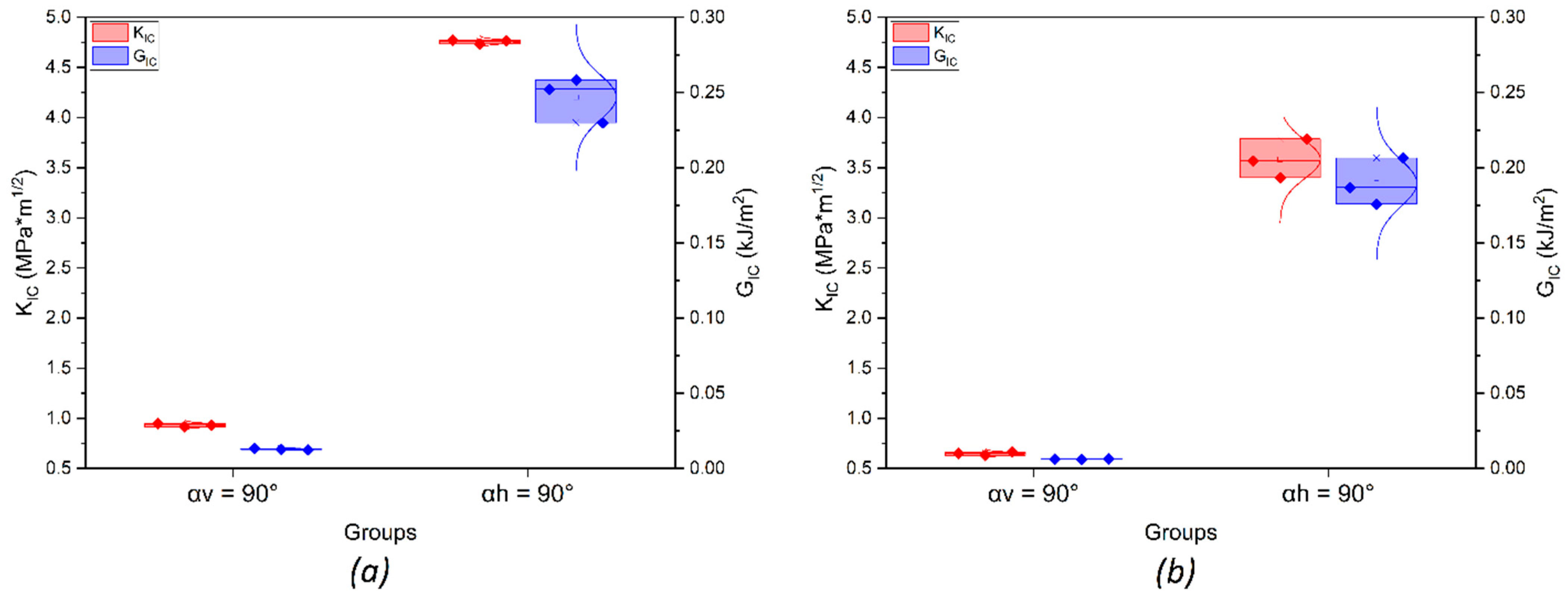
3.3. Critical Stress Intensity Factor and Critical Strain Energy Release Rate
4. Conclusions
Author Contributions
Funding
Institutional Review Board Statement
Informed Consent Statement
Data Availability Statement
Conflicts of Interest
References
- Plocher, J.; Panesar, A. Review on Design and Structural Optimisation in Additive Manufacturing: Towards next-Generation Lightweight Structures. Mater. Des. 2019, 183, 108164. [Google Scholar] [CrossRef]
- Guo, N.; Leu, M.C. Additive Manufacturing: Technology, Applications and Research Needs. Front. Mech. Eng. 2013, 8, 215–243. [Google Scholar] [CrossRef]
- Kumar, S.; Wardle, B.L.; Arif, M.F. Strength and Performance Enhancement of Bonded Joints by Spatial Tailoring of Adhesive Compliance via 3D Printing. ACS Appl. Mater. Interfaces 2017, 9, 884–891. [Google Scholar] [CrossRef]
- Kumar, S.; Wardle, B.L.; Arif, M.F.; Ubaid, J. Stress Reduction of 3D Printed Compliance-Tailored Multilayers. Adv. Eng. Mater. 2018, 20, 1700883. [Google Scholar] [CrossRef]
- Liljenhjerte, J.; Kumar, S. Pull-out Performance of 3D Printed Composites with Embedded Fins on the Fiber. Mater. Res. Soc. 2015, 1800, 2–7. [Google Scholar] [CrossRef]
- Liljenhjerte, J.; Upadhyaya, P.; Kumar, S. Hyperelastic Strain Measurements and Constitutive Parameters Identification of 3D Printed Soft Polymers by Image Processing. Addit. Manuf. 2016, 11, 40–48. [Google Scholar] [CrossRef]
- Rajan, K.; Samykano, M.; Kadirgama, K.; Harun, W.S.W.; Rahman, M.M. Fused Deposition Modeling: Process, Materials, Parameters, Properties, and Applications. Int. J. Adv. Manuf. Technol. 2022, 120, 1531–1570. [Google Scholar] [CrossRef]
- Valino, A.D.; Dizon, J.R.C.; Espera, A.H.; Chen, Q.; Messman, J.; Advincula, R.C. Advances in 3D Printing of Thermoplastic Polymer Composites and Nanocomposites. Prog. Polym. Sci. 2019, 98, 101162. [Google Scholar] [CrossRef]
- Das, A.; Marnot, A.E.C.; Fallon, J.J.; Martin, S.M.; Joseph, E.G.; Bortner, M.J. Material Extrusion-Based Additive Manufacturing with Blends of Polypropylene and Hydrocarbon Resins. ACS Appl. Polym. Mater. 2020, 2, 911–921. [Google Scholar] [CrossRef]
- Kurtz, S.M. An Overview of PEEK Biomaterials; Elsevier Inc.: Amsterdam, The Netherlands, 2012; ISBN 9781437744637. [Google Scholar]
- Mark, H.F. Acetylenic Polymers, Substituted. In Encyclopedia of Polymer Science and Technology; John Wiley & Sons: Hoboken, NJ, USA, 2001; Volume 4. [Google Scholar] [CrossRef]
- Wang, Y.; Müller, W.D.; Rumjahn, A.; Schmidt, F.; Schwitalla, A.D. Mechanical Properties of Fused Filament Fabricated PEEK for Biomedical Applications Depending on Additive Manufacturing Parameters. J. Mech. Behav. Biomed. Mater. 2021, 115, 104250. [Google Scholar] [CrossRef]
- Dua, R.; Rashad, Z.; Spears, J.; Dunn, G.; Maxwell, M. Applications of 3d-Printed Peek via Fused Filament Fabrication: A Systematic Review. Polymers 2021, 13, 4046. [Google Scholar] [CrossRef]
- Zanjanijam, A.R.; Major, I.; Lyons, J.G.; Lafont, U.; Devine, D.M. Fused Filament Fabrication of Peek: A Review of Process-Structure-Property Relationships. Polymers 2020, 12, 1665. [Google Scholar] [CrossRef]
- Sharma, G.; Vuppuluri, A.; Suresh, K. Essential Work of Fracture Studies of 3D Printed PEEK (Poly-Ether-Ether-Ketone) Polymer. Eng. Fract. Mech. 2022, 271, 108656. [Google Scholar] [CrossRef]
- Hart, K.R.; Dunn, R.M.; Sietins, J.M.; Hofmeister Mock, C.M.; Mackay, M.E.; Wetzel, E.D. Increased Fracture Toughness of Additively Manufactured Amorphous Thermoplastics via Thermal Annealing. Polymer 2018, 144, 192–204. [Google Scholar] [CrossRef]
- Hart, K.R.; Dunn, R.M.; Wetzel, E.D. Increased Fracture Toughness of Additively Manufactured Semi-Crystalline Thermoplastics via Thermal Annealing. Polymer 2020, 211, 123091. [Google Scholar] [CrossRef]
- McLauchlin, A.R.; Ghita, O.R.; Savage, L. Studies on the Reprocessability of Poly(Ether Ether Ketone) (PEEK). J. Mater. Process. Technol. 2014, 214, 75–80. [Google Scholar] [CrossRef]
- Javaid, M.; Haleem, A. Additive Manufacturing Applications in Medical Cases: A Literature Based Review. Alex. J. Med. 2018, 54, 411–422. [Google Scholar] [CrossRef]
- Lee, N. The Lancet Technology: 3D Printing for Instruments, Models, and Organs? Lancet 2016, 388, 1368. [Google Scholar] [CrossRef] [PubMed]
- Lupuleasa, D.; Drăgănescu, D.; Hîncu, L.; Tudosă, C.P.; Cioacă, D. Biocompatible Polymers for 3D Printing. Farmacia 2018, 66, 737–746. [Google Scholar] [CrossRef]
- Arif, M.F.; Kumar, S.; Varadarajan, K.M.; Cantwell, W.J. Performance of Biocompatible PEEK Processed by Fused Deposition Additive Manufacturing. Mater. Des. 2018, 146, 249–259. [Google Scholar] [CrossRef]
- Singh, D.; Singh, R.; Boparai, K.S. Development and Surface Improvement of FDM Pattern Based Investment Casting of Biomedical Implants: A State of Art Review. J. Manuf. Process. 2018, 31, 80–95. [Google Scholar] [CrossRef]
- Karimipour-Fard, P.; Behravesh, A.H.; Jones-Taggart, H.; Pop-Iliev, R.; Rizvi, G. Effects of Design, Porosity and Biodegradation on Mechanical and Morphological Properties of Additive-Manufactured Triply Periodic Minimal Surface Scaffolds. J. Mech. Behav. Biomed. Mater. 2020, 112, 104064. [Google Scholar] [CrossRef] [PubMed]
- Germain, L.; Fuentes, C.A.; van Vuure, A.W.; des Rieux, A.; Dupont-Gillain, C. 3D-Printed Biodegradable Gyroid Scaffolds for Tissue Engineering Applications. Mater. Des. 2018, 151, 113–122. [Google Scholar] [CrossRef]
- Singh, S.; Prakash, C.; Ramakrishna, S. 3D Printing of Polyether-Ether-Ketone for Biomedical Applications. Eur. Polym. J. 2019, 114, 234–248. [Google Scholar] [CrossRef]
- Kurtz, S.M.; Devine, J.N. PEEK Biomaterials in Trauma, Orthopedic, and Spinal Implants. Biomaterials 2007, 28, 4845–4869. [Google Scholar] [CrossRef] [PubMed]
- Das, A.; Chatham, C.A.; Fallon, J.J.; Zawaski, C.E.; Gilmer, E.L.; Williams, C.B.; Bortner, M.J. Current Understanding and Challenges in High Temperature Additive Manufacturing of Engineering Thermoplastic Polymers. Addit. Manuf. 2020, 34, 101218. [Google Scholar] [CrossRef]
- Liao, K. Performance Characterization and Modeling of a Composite Hip Prosthesis. Exp. Tech. 1994, 18, 33–38. [Google Scholar] [CrossRef]
- Gao, S.; Liu, R.; Xin, H.; Liang, H.; Wang, Y.; Jia, J. The Surface Characteristics, Microstructure and Mechanical Properties of Peek Printed by Fused Deposition Modeling with Different Raster Angles. Polymer 2021, 14, 77. [Google Scholar] [CrossRef]
- Kelsey, D.J.; Springer, G.S.; Goodman, S.B. Composite Implant for Bone Replacement. J. Compos. Mater. 1997, 31, 1593–1632. [Google Scholar] [CrossRef]
- Sicilia, A.; Cuesta, S.; Coma, G.; Arregui, I.; Guisasola, C.; Ruiz, E.; Maestro, A. Titanium Allergy in Dental Implant Patients: A Clinical Study on 1500 Consecutive Patients. Clin. Oral Implant. Res. 2008, 19, 823–835. [Google Scholar] [CrossRef]
- Ma, H.; Suonan, A.; Zhou, J.; Yuan, Q.; Liu, L.; Zhao, X.; Lou, X.; Yang, C.; Li, D.; Zhang, Y. gang PEEK (Polyether-Ether-Ketone) and Its Composite Materials in Orthopedic Implantation. Arab. J. Chem. 2021, 14, 102977. [Google Scholar] [CrossRef]
- Lommen, J.; Schorn, L.; Sproll, C.; Haussmann, J.; Kübler, N.R.; Budach, W.; Rana, M.; Tamaskovics, B. Reduction of CT Artifacts Using Polyetheretherketone (PEEK), Polyetherketoneketone (PEKK), Polyphenylsulfone (PPSU), and Polyethylene (PE) Reconstruction Plates in Oral Oncology. J. Oral Maxillofac. Surg. 2022, 80, 1272–1283. [Google Scholar] [CrossRef] [PubMed]
- Jiang, C.-P.; Cheng, Y.-C.; Lin, H.-W.; Chang, Y.-L.; Pasang, T.; Lee, S.-Y. Optimization of FDM 3D Printing Parameters for High Strength PEEK Using the Taguchi Method and Experimental Validation. Rapid Prototyp. J. 2022, 28, 1260–1271. [Google Scholar] [CrossRef]
- Yang, C.; Tian, X.; Li, D.; Cao, Y.; Zhao, F.; Shi, C. Influence of Thermal Processing Conditions in 3D Printing on the Crystallinity and Mechanical Properties of PEEK Material. J. Mater. Process. Technol. 2017, 248, 1–7. [Google Scholar] [CrossRef]
- Wang, Y.; Müller, W.D.; Rumjahn, A.; Schwitalla, A. Parameters Influencing the Outcome of Additive Manufacturing of Tiny Medical Devices Based on PEEK. Materials 2020, 13, 466. [Google Scholar] [CrossRef]
- Challa, B.T.; Gummadi, S.K.; Elhattab, K.; Ahlstrom, J.; Sikder, P. In-House Processing of 3D Printable Polyetheretherketone (PEEK) Filaments and the Effect of Fused Deposition Modeling Parameters on 3D-Printed PEEK Structures. Int. J. Adv. Manuf. Technol. 2022, 121, 1675–1688. [Google Scholar] [CrossRef]
- Akhoundi, B.; Nabipour, M.; Hajami, F.; Shakoori, D. An Experimental Study of Nozzle Temperature and Heat Treatment (Annealing) Effects on Mechanical Properties of High-Temperature Polylactic Acid in Fused Deposition Modeling. Polym. Eng. Sci. 2020, 60, 979–987. [Google Scholar] [CrossRef]
- Fitzharris, E.R.; Watt, I.; Rosen, D.W.; Shofner, M.L. Interlayer Bonding Improvement of Material Extrusion Parts with Polyphenylene Sulfide Using the Taguchi Method. Addit. Manuf. 2018, 24, 287–297. [Google Scholar] [CrossRef]
- Liaw, C.Y.; Tolbert, J.W.; Chow, L.W.; Guvendiren, M. Interlayer Bonding Strength of 3D Printed PEEK Specimens. Soft Matter 2021, 17, 4775–4789. [Google Scholar] [CrossRef]
- Wu, W.; Geng, P.; Li, G.; Zhao, D.; Zhang, H.; Zhao, J. Influence of Layer Thickness and Raster Angle on the Mechanical Properties of 3D-Printed PEEK and a Comparative Mechanical Study between PEEK and ABS. Materials 2015, 8, 5834–5846. [Google Scholar] [CrossRef]
- Deng, X.; Zeng, Z.; Peng, B.; Yan, S.; Ke, W. Mechanical Properties Optimization of Poly-Ether-Ether-Ketone via Fused Deposition Modeling. Materials 2018, 11, 216. [Google Scholar] [CrossRef]
- Zhao, Y.; Zhao, K.; Li, Y.; Chen, F. Mechanical Characterization of Biocompatible PEEK by FDM. J. Manuf. Process. 2020, 56, 28–42. [Google Scholar] [CrossRef]
- Tardif, X.; Pignon, B.; Boyard, N.; Schmelzer, J.W.P.; Sobotka, V.; Delaunay, D.; Schick, C. Experimental Study of Crystallization of PolyEtherEtherKetone (PEEK) over a Large Temperature Range Using a Nano-Calorimeter. Polym. Test. 2014, 36, 10–19. [Google Scholar] [CrossRef]
- Balani, S.B. Additive Manufacturing of the High-Performance Thermoplastics: Experimental Study and Numerical Simulation of the Fused Filament Fabricatio. Ph.D. Thesis, Institut National Polytechnique de Toulouse, Toulouse, France, 2019. [Google Scholar]
- Abdelaziz, Y.; Hamouine, A. A Survey of the Extended Finite Element. Comput. Struct. 2008, 86, 1141–1151. [Google Scholar] [CrossRef]
- Belytschko, T.; Black, T. Elastic Crack Growth in Finite Elements with Minimal Remeshing. Int. J. Numer. Methods Eng. 1999, 45, 601–620. [Google Scholar] [CrossRef]
- Zhang, C.; Cao, P.; Cao, Y.; Li, J. Using Finite Element Software to Simulation Fracture Behavior of Three-Point Bending Beam with Initial Crack. J. Softw. 2013, 8, 1145–1150. [Google Scholar] [CrossRef]
- Du, Z. Extended Finite Element Method (XFEM) in Abaqus Dassault System; Simulia: Johnston, RI, USA, 2016; pp. 1–61. [Google Scholar]
- Remmers, J.J.C.; de Borst, R.; Needleman, A. The Simulation of Dynamic Crack Propagation Using the Cohesive Segments Method. J. Mech. Phys. Solids 2008, 56, 70–92. [Google Scholar] [CrossRef]
- Allum, J.; Gleadall, A.; Silberschmidt, V.V. Fracture of 3D-Printed Polymers: Crucial Role of Filament-Scale Geometric Features. Eng. Fract. Mech. 2020, 224, 106818. [Google Scholar] [CrossRef]


| Process Parameter | Value |
|---|---|
| Nozzle movement speed, mm/min | 2100 |
| Nozzle temperature, °C | 435 |
| Table temperature, °C | 145 |
| Chamber temperature, °C | 75 |
| Layer height, mm | 0.1 |
| Extrusion width, mm | 0.4–0.6 |
| Infill | Straight-line |
| Infill density, % | 100 |
| Airflow, % | 100 |
| α = 45° | α = 90° | α = 180° | |
|---|---|---|---|
| Elastic modulus, E (GPa) | 2.53 ± 0.23 | 4.27 ± 0.17 | 3.92 ± 0.77 |
| Tensile strength, (MPa) | 23.91 ± 4.18 | 29.77 ± 1.21 | 82.34 ± 4.08 |
| Resilience (J·m−3) | 12.59 ± 2.83 | 17.90 ± 0.23 | 288.93 ± 42.88 |
| Toughness (J·m−3) | 13.73 ± 1.35 | 18.19 ± 0.23 | 1121.16 ± 210.30 |
| Nozzle 0.6 mm | Nozzle 0.4 mm | |||
|---|---|---|---|---|
| α = 45 | α = 90° | α = 180° | α = 180° | |
| Elastic modulus, E (GPa) | 2.53 ± 0.15 | 4.68 ± 0.23 | 4.74 ± 0.12 | 8.06 ± 0.11 |
| Tensile strength, (MPa) | 46.53 ± 8.81 | 43.11 ± 4.58 | 127.76 ± 6 | 128.15 ± 5.41 |
| Resilience (J·m−3) | 53.13 ± 24.88 | 36.06 ± 8.45 | 270.78 ± 32.79 | 202.02 ± 40.46 |
| Toughness (J·m−3) | 56.27 ± 23.07 | 36.10 ± 8.45 | 271.22 ± 33.00 | 202.19 ± 40.47 |
| As-Delivered Filament | Standard Printed Samples without Heat Treatment | |||
|---|---|---|---|---|
| α = 45° | α = 90° | α = 180° | ||
| Elastic modulus, E (GPa) | 4.15 ± 0.48 | 2.53 ± 0.23 | 4.27 ± 0.17 | 3.92 ± 0.77 |
| Tensile strength, (MPa) | 89.39 ± 5.71 | 23.91 ± 4.18 | 29.77 ± 1.21 | 82.34 ± 4.08 |
| Resilience (J·m−3) | 231.74 ± 42.90 | 12.59 ± 2.83 | 17.90 ± 0.23 | 288.93 ± 42.88 |
| Toughness (J·m−3) | 10,508.89 ± 1117.59 | 13.73 ± 1.35 | 18.19 ± 0.23 | 1121.16 ± 210.30 |
| Without Heat Treatment | With Heat Treatment | |||
|---|---|---|---|---|
| Nozzle 0.4 mm | Nozzle 0.6 mm | Nozzle 0.4 mm | Nozzle 0.6 mm | |
| Elastic modulus, E (GPa) | 4.08 ± 0.85 | 4.12 ± 0.31 | 4.35 ± 0.12 | 4.43 ± 0.38 |
| Tensile strength, (MPa) | 43.51 ± 3.11 | 42.21 ± 0.41 | 82.08 ± 2.62 | 83.32 ± 10.16 |
| Resilience (J·m−3) | 44.53 ± 9.09 | 59.19 ± 1.94 | 139.55 ± 25.82 | 149.53 ± 28.60 |
| Toughness (J·m−3) | 872.48 ± 76.02 | 1160.06 ± 43.14 | 489.27 ± 312.46 | 394.01 ± 113.98 |
| Samples without Heat Treatment | Samples with Heat Treatment | |||
|---|---|---|---|---|
| Vertical Orientation | Horizontal Orientation | Vertical Orientation | Horizontal Orientation | |
| Critical stress intensity factor, () | 0.64 ± 0.02 | 3.58 ± 0.20 | 0.93 ± 0.02 | 4.76 ± 0.02 |
| Critical strain energy release rate, (kJ/) | 0.01 ± 0.01 | 0.21 ± 0.02 | 0.02 ± 0.01 | 0.25 ± 0.02 |
| Tensile strength, (MPa) | 0.22 ± 0.01 | 1.66 ± 0.10 | 0.33 ± 0.02 | 2.16 ± 0.03 |
Publisher’s Note: MDPI stays neutral with regard to jurisdictional claims in published maps and institutional affiliations. |
© 2022 by the authors. Licensee MDPI, Basel, Switzerland. This article is an open access article distributed under the terms and conditions of the Creative Commons Attribution (CC BY) license (https://creativecommons.org/licenses/by/4.0/).
Share and Cite
Vindokurov, I.; Pirogova, Y.; Tashkinov, M.; Silberschmidt, V.V. Effect of Heat Treatment on Elastic Properties and Fracture Toughness of Fused Filament Fabricated PEEK for Biomedical Applications. Polymers 2022, 14, 5521. https://doi.org/10.3390/polym14245521
Vindokurov I, Pirogova Y, Tashkinov M, Silberschmidt VV. Effect of Heat Treatment on Elastic Properties and Fracture Toughness of Fused Filament Fabricated PEEK for Biomedical Applications. Polymers. 2022; 14(24):5521. https://doi.org/10.3390/polym14245521
Chicago/Turabian StyleVindokurov, Ilia, Yulia Pirogova, Mikhail Tashkinov, and Vadim V. Silberschmidt. 2022. "Effect of Heat Treatment on Elastic Properties and Fracture Toughness of Fused Filament Fabricated PEEK for Biomedical Applications" Polymers 14, no. 24: 5521. https://doi.org/10.3390/polym14245521
APA StyleVindokurov, I., Pirogova, Y., Tashkinov, M., & Silberschmidt, V. V. (2022). Effect of Heat Treatment on Elastic Properties and Fracture Toughness of Fused Filament Fabricated PEEK for Biomedical Applications. Polymers, 14(24), 5521. https://doi.org/10.3390/polym14245521