
Electrical Tree Characteristics of Bisphenol A Epoxy Resin/Maleopimaric Anhydride Curing System

 , and
, and
Abstract
:1. Introduction
2. Materials and Methods
2.1. Materials
2.2. Preparations
2.3. Methods
- (1)
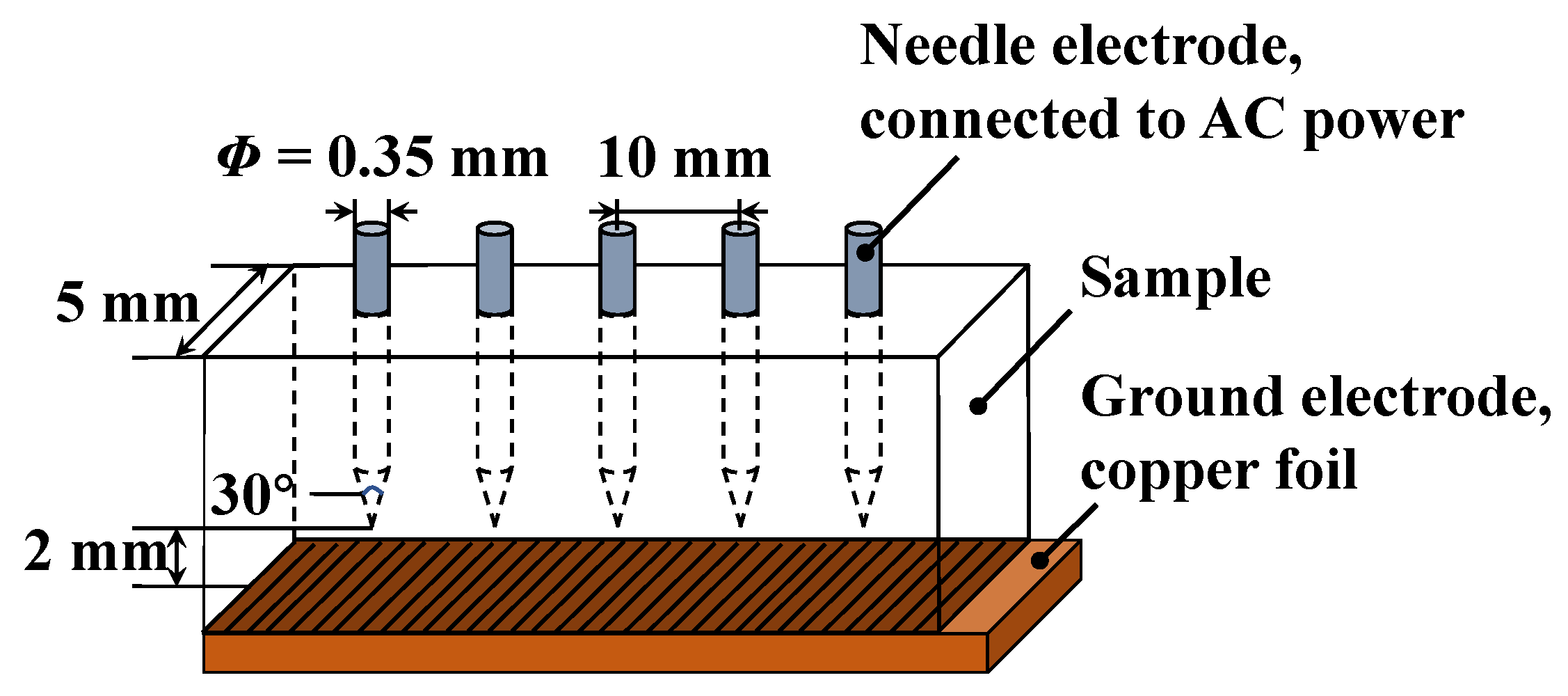
- Electrical tree initiation test: An AC voltage was applied to the epoxy resin specimen through the “needle-plate” electrode model. Beginning from 6 kV, the voltage was increased by 1 kV every 30 s until an electrical tree was triggered at the tip of the needle; then, the AC power was immediately turned off. The value at the moment of initiation was recorded as the specimen electrical tree starting voltage.
- (2)
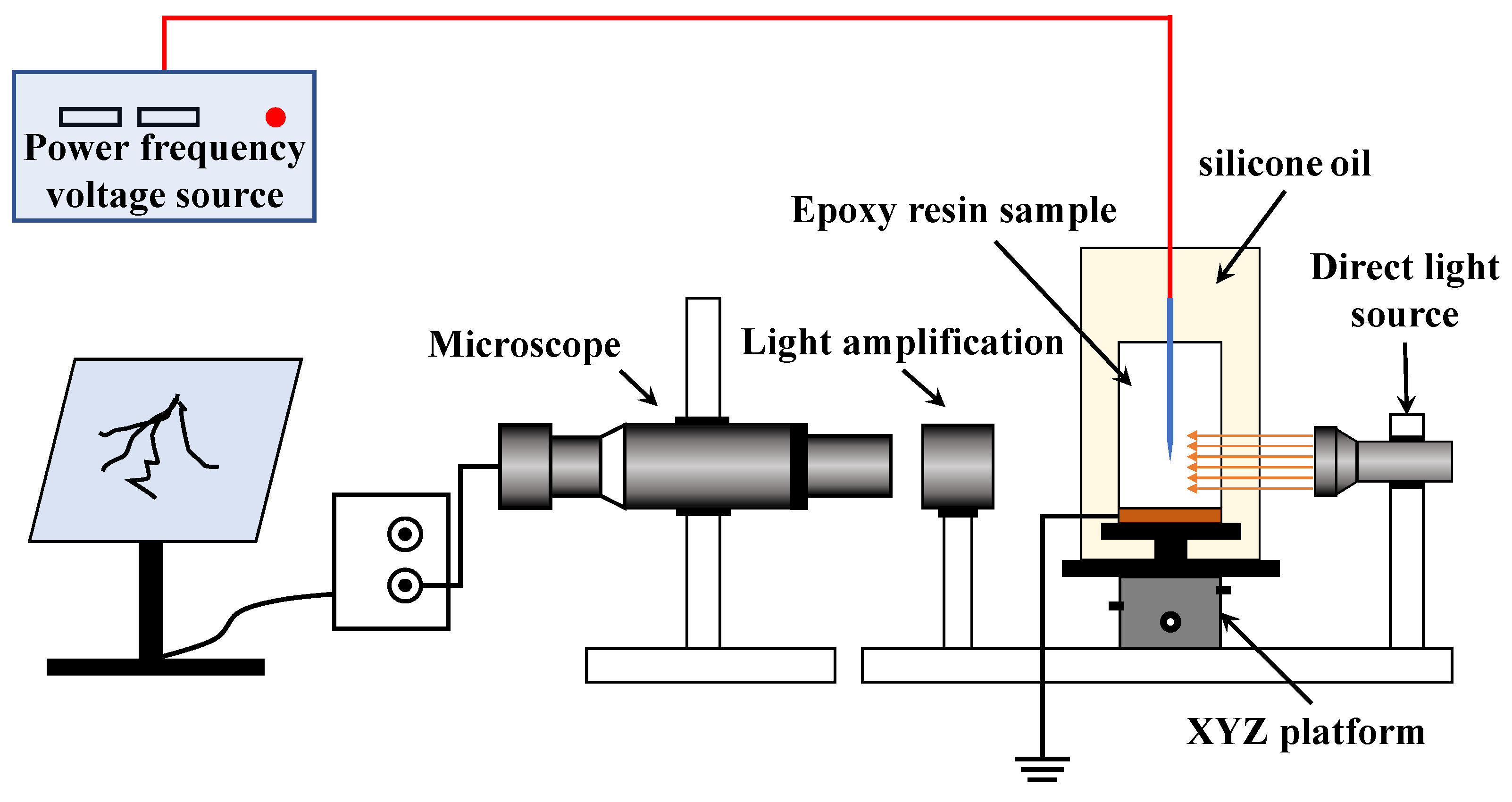
- Electrical tree growth test: After an electrical tree initiated, each specimen received an 18-kilovolt AC frequency voltage. At the same time, the growth of the electrical tree was recorded using a microscopic imaging system at a frequency of 10 s/frame.
3. Results
3.1. Electrical Tree Initiating Characteristics
3.2. Electrical Tree Developing Characteristics
4. Discussion
4.1. Microstructure of Blended Systems
4.2. Discussion of Electrical Tree Initiation Characteristics
4.3. Discussion of Electrical Tree Growth Characteristics
5. Conclusions
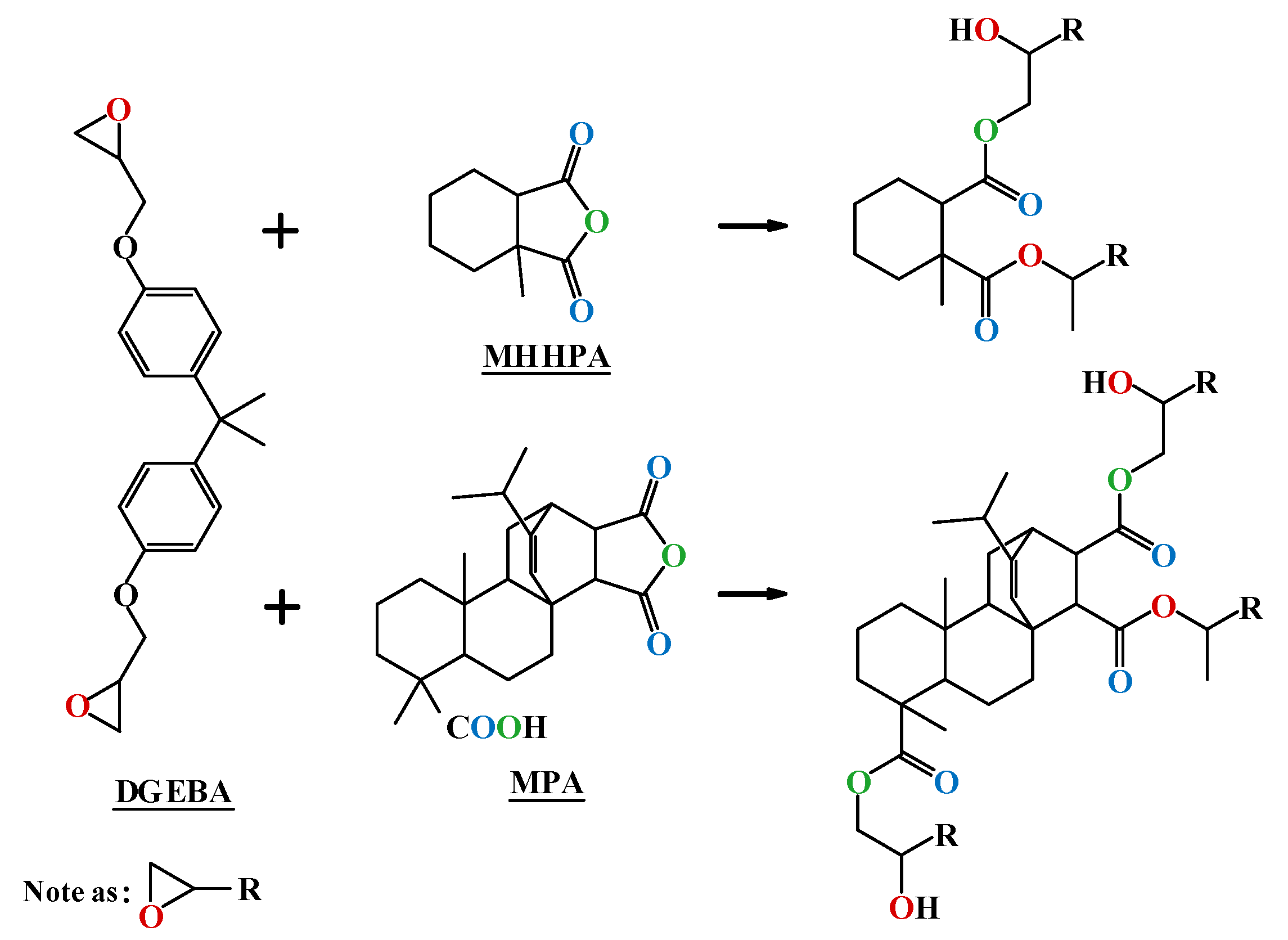
- With an increase in MPA content, the free volume percentage of the curing system showed a trend of initially increasing and then stabilizing. MPA introduces a large number of hydrogen phenanthrene ring polar side groups to the blended system; as a result, the bond energy and bond angle energy of the blended system gradually increase, and the van der Waals force also increases simultaneously;
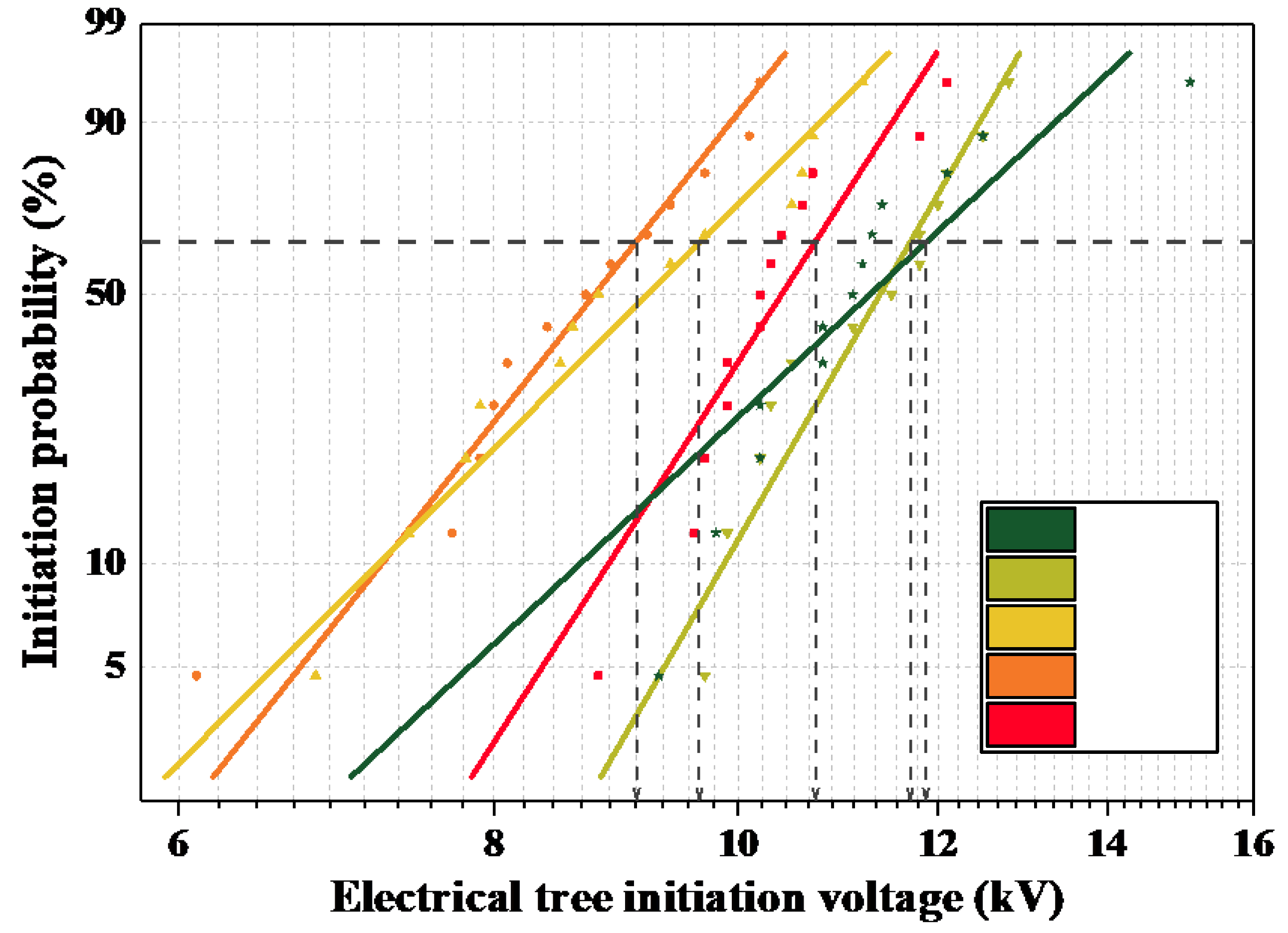
- With an increase in MPA content, the initiation voltage of the electrical tree showed a trend of initially decreasing and then increasing; the initiation voltage of MPA4 increased by 11.11% compared with that of the petroleum-based control group. With an increase in MPA content, when MPA ≤ 10%, the initiation voltage decreased due to a decrease in the free volume ratio of the blended system; when MPA ≥ 20%, the initiation voltage continued to increase as a result of an increase in molecular rigidity.
- The rigid structure of the hydrogen phenanthrene ring in MPA has an inhibitory effect on the growth of electrical trees. The electrical trees of the petroleum-based control group showed “branch-and-pine” shapes, with faster development and darker color under 18-kilovolt AC voltage. After the introduction of MPA, the electrical trees showed “branch” shapes with cross-colors and narrow widths. When the MPA content exceeded 20%, the hysteresis phenomenon appeared after 600 s.
Author Contributions
Funding
Institutional Review Board Statement
Informed Consent Statement
Data Availability Statement
Conflicts of Interest
References
- Liu, X.; Xin, W.; Zhang, J. Rosin-based acid anhydrides as alternatives to petrochemical curing agents. Green Chem. 2009, 11, 1018–1025. [Google Scholar] [CrossRef]
- Moreira, V.B.; Alemán, C.; Rintjema, J.; Bravo, F.; Kleij, A.W.; Armelin, E. A Biosourced Epoxy Resin for Adhesive Thermoset Applications. ChemSusChem 2022, 15, e202102624. [Google Scholar] [CrossRef] [PubMed]
- Nhuapeng, W.; Chintonguyad, T.; Thamjaree, W. The Influence of Alkaline Treatment on Tensile Properties of Short Bamboo Fiber Reinforced Epoxy Resin Biocomposites. J. Phys. Conf. Ser. 2022, 2175, 012004. [Google Scholar] [CrossRef]
- Saba, N.; Jawaid, M.; Alothman, O.Y.; Tahir, P.M.; Hassan, A. Recent advances in epoxy resin, natural fiber-reinforced epoxy composites and their applications. J. Reinf. Plast. Compos. 2016, 35, 447–470. [Google Scholar] [CrossRef]
- Vedernikov, A.; Nasonov, Y.; Korotkov, R.; Gusev, S.; Akhatov, I.; Safonov, A. Effects of additives on the cure kinetics of vinyl ester pultrusion resins. J. Compos. Mater. 2021, 55, 2921–2937. [Google Scholar] [CrossRef]
- Wang, Z.; Wang, Y.; Liu, W.; Derradji, M.; Qiu, J.; Wang, J.; Yuan, Z.; Guo, Z. Diatomite-filled epoxy resin composites: Curing behavior, dielectric, and thermal properties. Polym. Compos. 2022, 43, 422–429. [Google Scholar]
- Baghad, A.; Mabrouk, K.E. The isothermal curing kinetics of a new carbon fiber/epoxy resin and the physical properties of its autoclaved composite laminates. Mater. Today Proc. 2022, 57, 922–929. [Google Scholar] [CrossRef]
- Zebouchi, N.; Haddad, M.A. A Review on Real-Size Epoxy Cast Resin Insulators for Compact High Voltage Direct Current Gas Insulated Switchgears (GIS) and Gas Insulated Transmission Lines (GIL)—Current Achievements and Envisaged Research and Development. Energies 2020, 13, 6416. [Google Scholar] [CrossRef]
- Chen, Y.; Ding, L.; Cui, C.; Liu, L.; Huang, Y. High-epoxy value bio-based epoxy emulsion reinforced interfacial properties of carbon fiber/epoxy composites. J. Appl. Polym. Sci. 2022, 139, 51855. [Google Scholar] [CrossRef]
- Moreira, V.B.; Rintjema, J.; Bravo, F.; Kleij, A.W.; Franco, L.; Puiggalí, J.; Alemán, C.; Armelin, E. Novel Biobased Epoxy Thermosets and Coatings from Poly(limonene carbonate) Oxide and Synthetic Hardeners. ACS Sustain. Chem. Eng. 2022, 10, 2708–2719. [Google Scholar] [CrossRef]
- Song, L.; Meng, Y.; Lv, P.; Liu, W.; Pang, H. Preparation of a Dmap-Catalysis Lignin Epoxide and the Study of Its High Mechanical-Strength Epoxy Resins with High-Biomass Content. Polymers 2021, 13, 750. [Google Scholar] [CrossRef] [PubMed]
- Scarton, C.T.; Guerra, N.B.; Giovanela, M.; Moresco, S.; Crespo, J. Evaluation of natural and epoxidized vegetable oil in elastomeric compositions for tread rubber. J. Elastomers Plast. 2022, 54, 264–278. [Google Scholar] [CrossRef]
- Liu, H.; Cui, S.; Shang, S.; Wang, D.; Song, J. Properties of rosin-based waterborne polyurethanes/cellulose nanocrystals composites. Carbohyd. Polym. 2013, 96, 510–515. [Google Scholar] [CrossRef] [PubMed]
- Wang, H.; Liu, X.; Liu, B.; Zhang, J.; Xian, M. Synthesis of rosin-based flexible anhydride-type curing agents and properties of the cured epoxy. Polym. Int. 2009, 58, 1435–1441. [Google Scholar] [CrossRef]
- Zhao, Y.; Zhang, G.; Han, D.; Li, K.; Qiu, Z.; Yang, F. Experimental Study on Insulation Properties of Epoxy Casting Resins Using High-frequency Square Waveforms. CSEE J. Power Energy Syst. 2021, 7, 1227–1237. [Google Scholar]
- Zhang, C.; Wang, S.; Fu, H.; Cheng, Z.; Li, C. Effect of Bipolar Square Wave Voltage with Varied Frequencies on Electrical Tree Growth in Epoxy Resin. IEEE Trans. Dielectr. Electr. Insul. 2021, 28, 806–814. [Google Scholar] [CrossRef]
- Yuan, Z.; Wang, C.; Tu, Y.; Wang, C.; Akram, S. Growth Law of Electrical Tree in Glass/Epoxy Resin Composite. In IEEE Transactions on Dielectrics and Electrical Insulation: A Publication of the IEEE Dielectrics and Electrical Insulation Society; IEEE: New York, NY, USA, 2021. [Google Scholar]
- Dissado, L.A.; Dodd, S.J.; Champion, J.V.; Williams, P.I.; Alison, J.M. Propagation of electrical tree structures in solid polymeric insulation. IEEE Trans. Dielectr. Electr. Insul. 1997, 4, 259–279. [Google Scholar] [CrossRef]
- Azhar, K.; Amin, S. Modeling the effect of uniform and nonuniform dispersion of nanofillers on electrical tree propagation in polyethylene dielectric. J. Adv. Dielectr. 2022, 12, 2250006-6. [Google Scholar] [CrossRef]
- Butler, T.; Bunton, C.; Ryou, H.; Dyatkin, B.; Weise, N.; Laskoski, M. Influence of molecular weight on thermal and mechanical properties of bisphenol A-based phthalonitrile resins. J. Appl. Polym. Sci. 2022, 139, 51783. [Google Scholar] [CrossRef]
- Xing, X.; Niu, X.; Liu, Y.; Yang, C.; Jing, X. In-depth understanding on the early stage of phenolic resin thermal pyrolysis through ReaxFF-molecular dynamics simulation. Polym. Degrad. Stab. 2021, 186, 109534. [Google Scholar] [CrossRef]
- Odegard, G.M.; Patil, S.U.; Deshpande, P.; Kanhaiya, K.; Winetrout, J.; Heinz, H.; Shah, S.; Maiaru, M. Molecular Dynamics Modeling of Epoxy Resins using the Reactive Interface Force Field. Macromolecules 2021, 54, 9815–9824. [Google Scholar] [CrossRef]
- Wang, T.; Li, D.; Zhang, G. Molecular Dynamics Simulations of Interface Properties and Key Physical Properties of Nanodielectrics Manufactured With Epoxy Resin Doped With Metal Nanoparticles. IEEE Access 2021, 9, 34231–34239. [Google Scholar] [CrossRef]
- Ma, S.; Chen, P.; Xu, J.; Chen, G.; Xiong, X. Directional Control of the Mechanical Properties of a Resin-Cross-Linking System: A Molecular Dynamics Study. Ind. Eng. Chem. Res. 2021, 60, 11621–11626. [Google Scholar] [CrossRef]
- Wu, X.; Liu, W.; Shi, F.; Yang, L.; Zhang, C. Constructing three-imensional boron nitride network for highly thermally conductive epoxy resin composites. Polym. Compos. 2022, 43, 1711–1717. [Google Scholar] [CrossRef]


| Sample | MPA0 | MPA1 | MPA2 | MPA3 | MPA4 |
|---|---|---|---|---|---|
| Ui 1/kV | 10.80 | 9.26 | 9.82 | 11.78 | 12.04 |
| Emax 2/kV·mm−1 | 1291.06 | 1107.02 | 1173.94 | 1408.66 | 1439.37 |
| Reagents | MPA0 1 (K = 0%) | MPA1 (K = 10%) | MPA2 (K = 20%) | MPA3 (K = 30%) | MPA4 (K = 40%) |
|---|---|---|---|---|---|
| DGEBA | 100 | 100 | 100 | 100 | 100 |
| MPA | 0 | 7.58 | 15.82 | 24.80 | 34.62 |
| MHHPA | 72.85 | 68.27 | 63.29 | 57.86 | 51.93 |
| DMP-30 | 0.86 | 0.87 | 0.89 | 0.91 | 0.93 |
Publisher’s Note: MDPI stays neutral with regard to jurisdictional claims in published maps and institutional affiliations. |
© 2022 by the authors. Licensee MDPI, Basel, Switzerland. This article is an open access article distributed under the terms and conditions of the Creative Commons Attribution (CC BY) license (https://creativecommons.org/licenses/by/4.0/).
Share and Cite
Liu, H.; Wu, X.; Guo, Z.; Dong, P.; Ge, Q.; Wei, L.; Sun, Z. Electrical Tree Characteristics of Bisphenol A Epoxy Resin/Maleopimaric Anhydride Curing System. Polymers 2022, 14, 3867. https://doi.org/10.3390/polym14183867
Liu H, Wu X, Guo Z, Dong P, Ge Q, Wei L, Sun Z. Electrical Tree Characteristics of Bisphenol A Epoxy Resin/Maleopimaric Anhydride Curing System. Polymers. 2022; 14(18):3867. https://doi.org/10.3390/polym14183867
Chicago/Turabian StyleLiu, Hechen, Xuan Wu, Zhanpeng Guo, Peng Dong, Qi Ge, Liwei Wei, and Zhanglin Sun. 2022. "Electrical Tree Characteristics of Bisphenol A Epoxy Resin/Maleopimaric Anhydride Curing System" Polymers 14, no. 18: 3867. https://doi.org/10.3390/polym14183867
APA StyleLiu, H., Wu, X., Guo, Z., Dong, P., Ge, Q., Wei, L., & Sun, Z. (2022). Electrical Tree Characteristics of Bisphenol A Epoxy Resin/Maleopimaric Anhydride Curing System. Polymers, 14(18), 3867. https://doi.org/10.3390/polym14183867