
Numerical Simulation of the Bearing Capacity of Variotropic Short Concrete Beams Reinforced with Polymer Composite Reinforcing Bars

 ,
, 
 ,
,  ,
, 
 and
and
Abstract
:1. Introduction
2. Materials and Methods
2.1. Materials
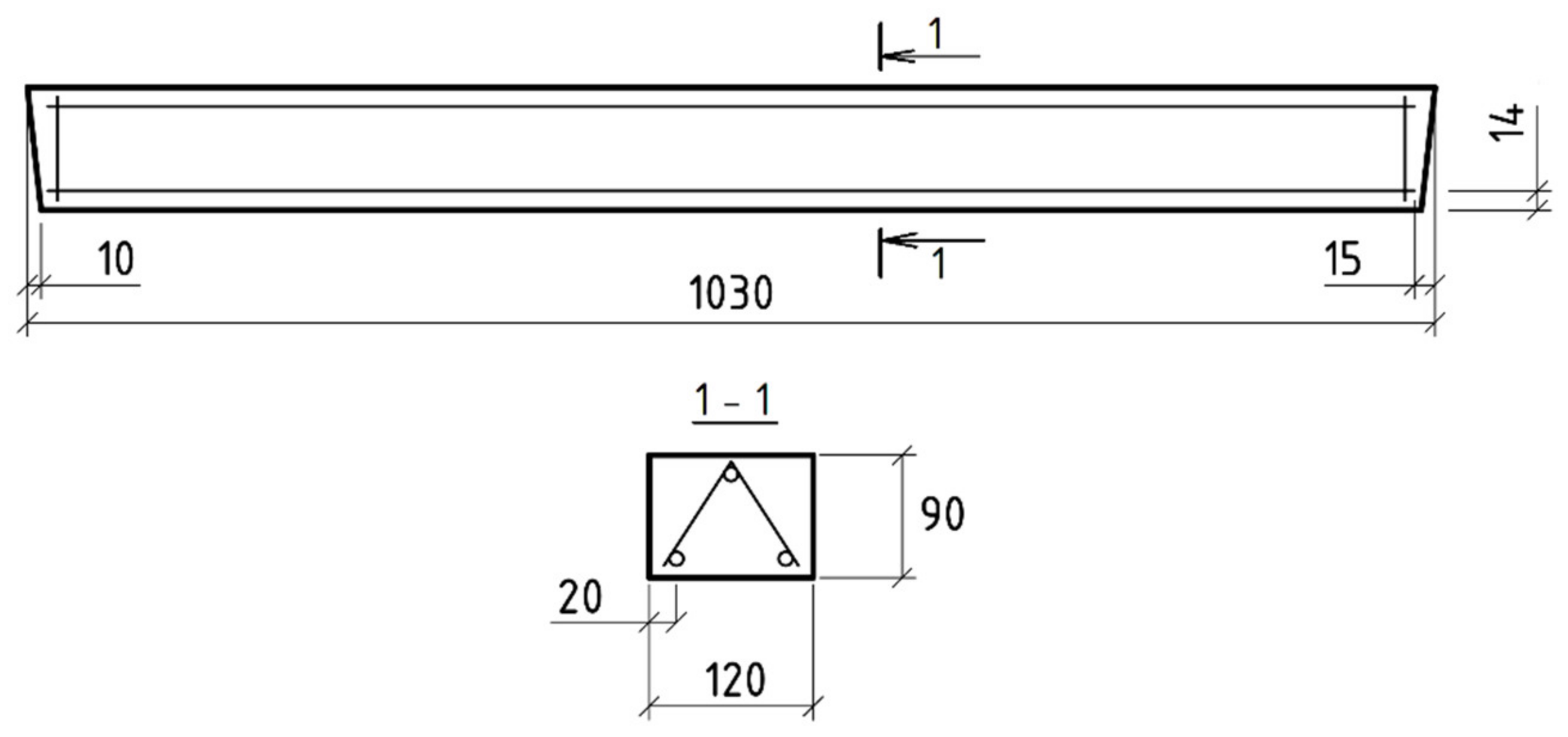
2.2. Beam Design
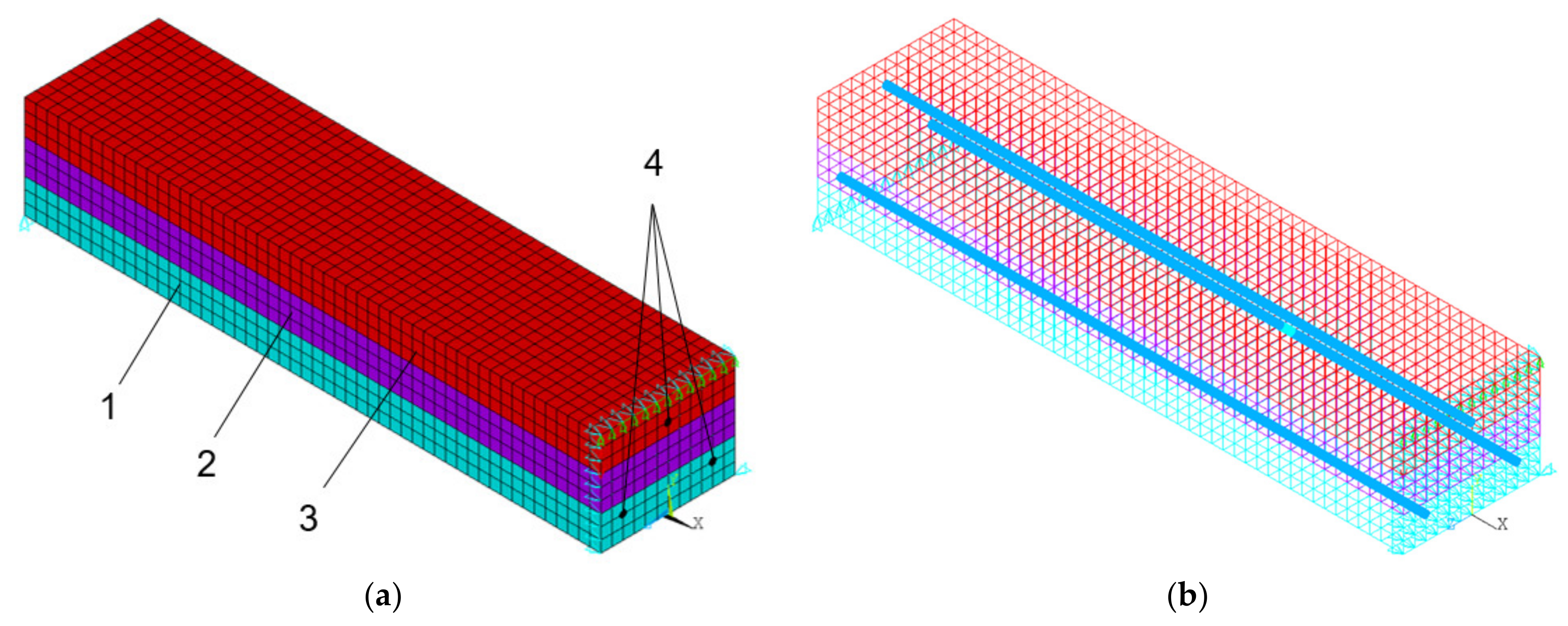
2.3. Simulation Methods
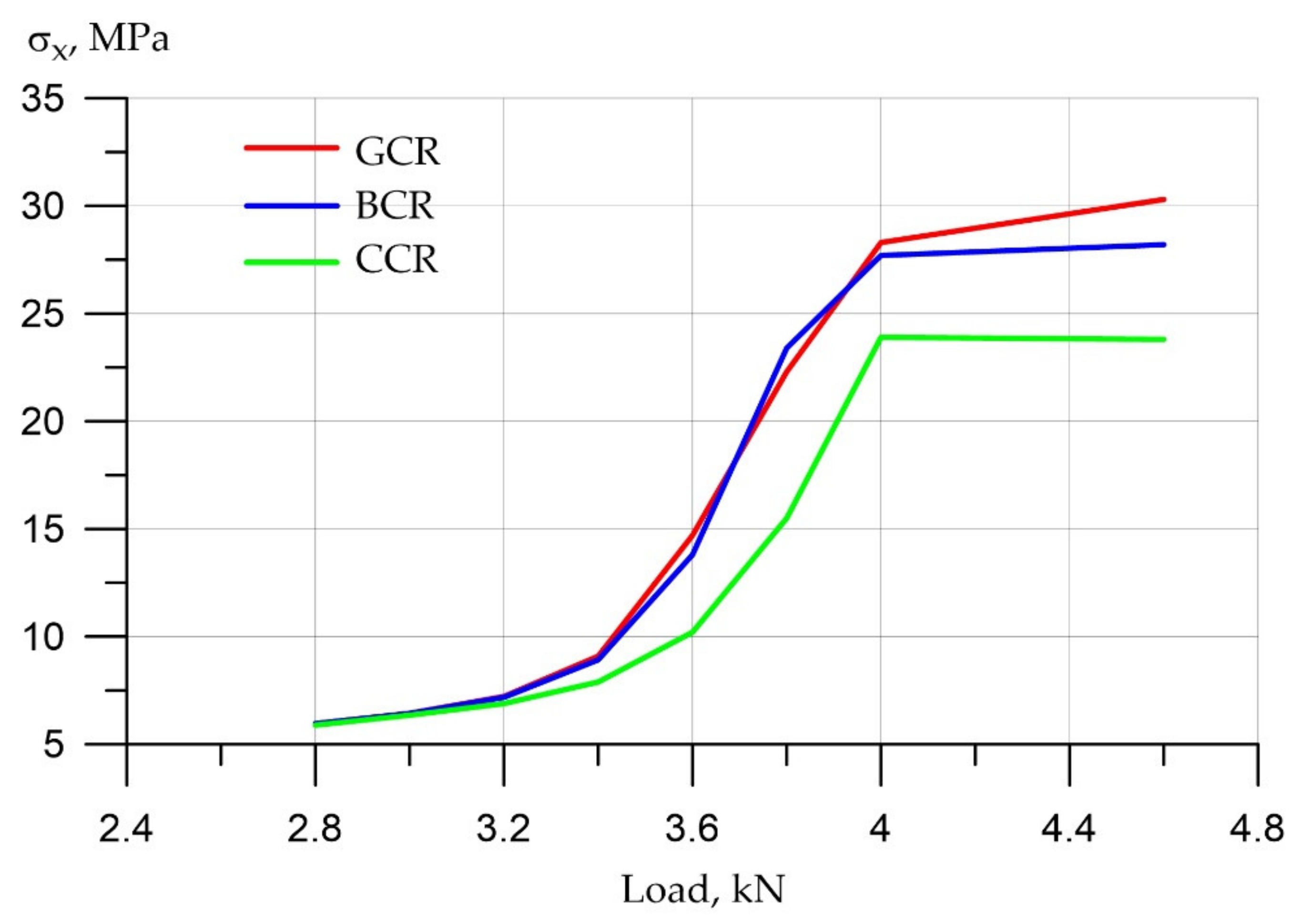
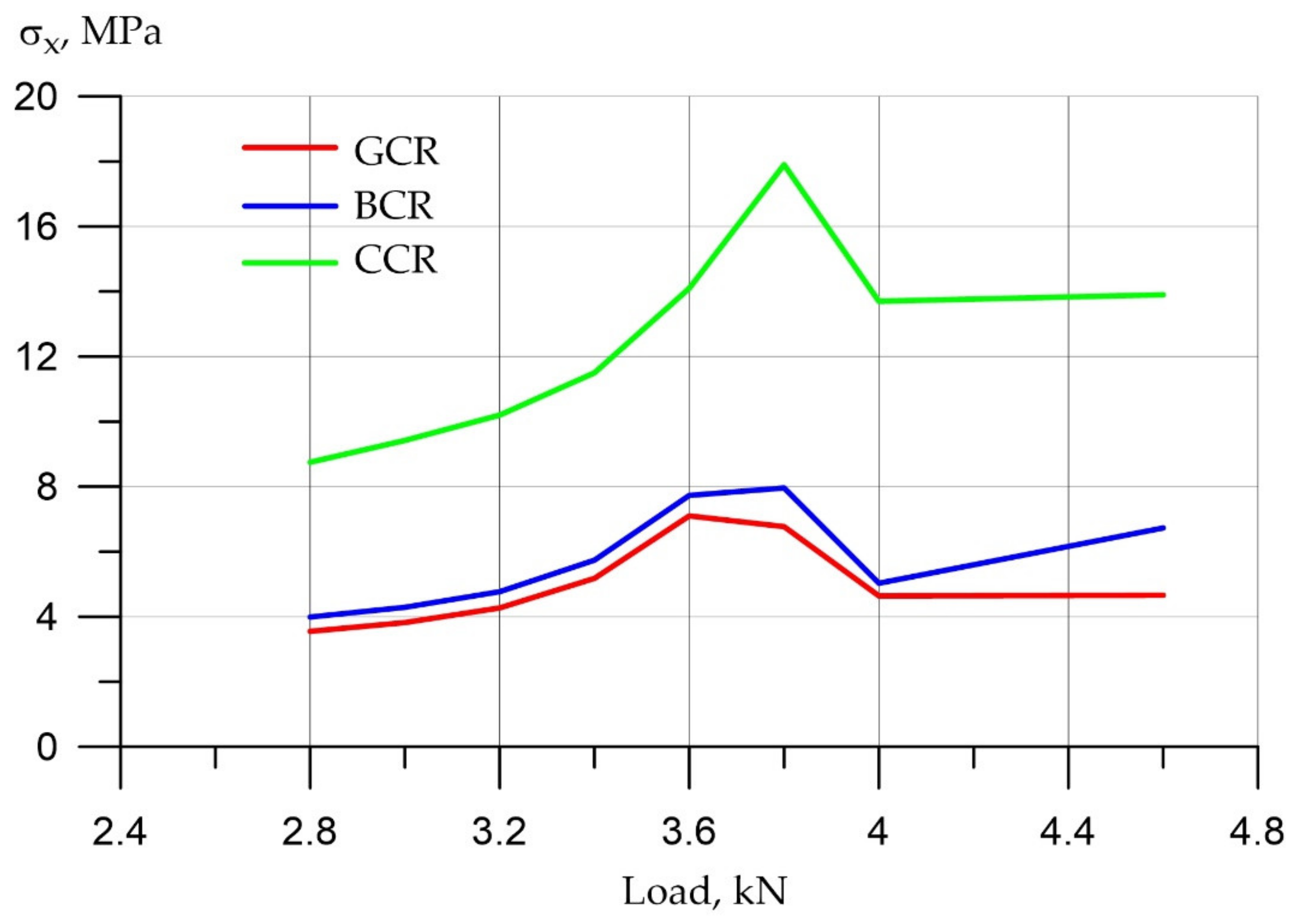
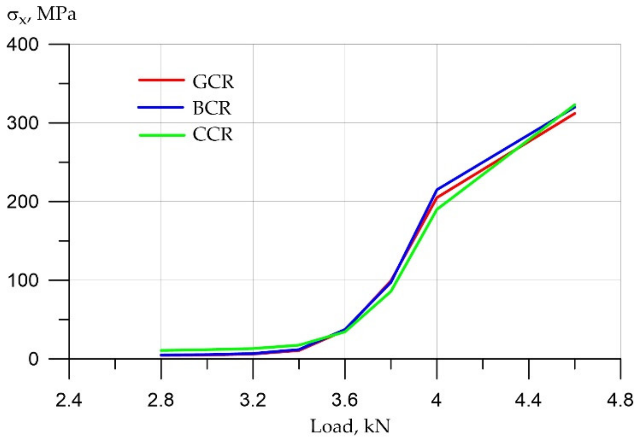
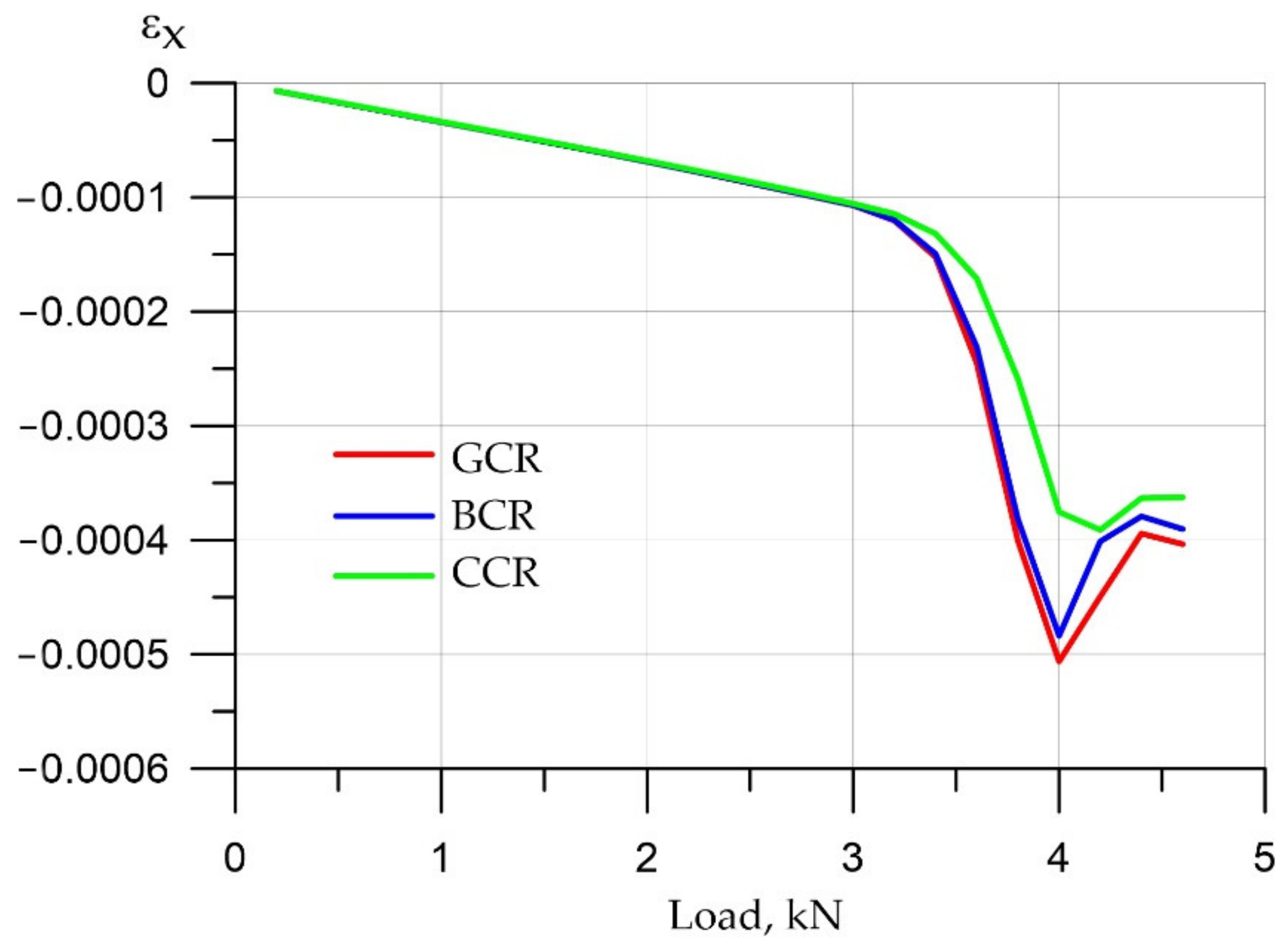
- Variotropic concrete reinforced with fiberglass rebar (GCR).
- Variotropic concrete reinforced with basalt composite rebar (BCR).
- Variotropic concrete reinforced with carbon composite rebar (CCR).
- All nodes with coordinate x = 0 are fixed in the direction of the Ox axis.
- All nodes with coordinates x = −l/2; y = 0 are fixed in the direction of the Oy axis, where l is the length of the beam.
- The node with coordinates x = 0; y = 0; z = −b/2 is fixed in the direction of the Oz axis, where b is the width of the beam.
- All nodes with coordinates x = 0; y = h are connected in the direction of the Oy axis, where h is the height of the beam.
- Force F = 7 kN is applied vertically down to the node with coordinates x = 0; y = h; z = b/2.
- (1)
- polymer composite-reinforced bending elements of the rectangular section;
- (2)
- transversally isotropic bending-reinforced concrete elements;
- (3)
- transversally isotropic polymer composite-reinforced bending elements.
3. Results and Discussion
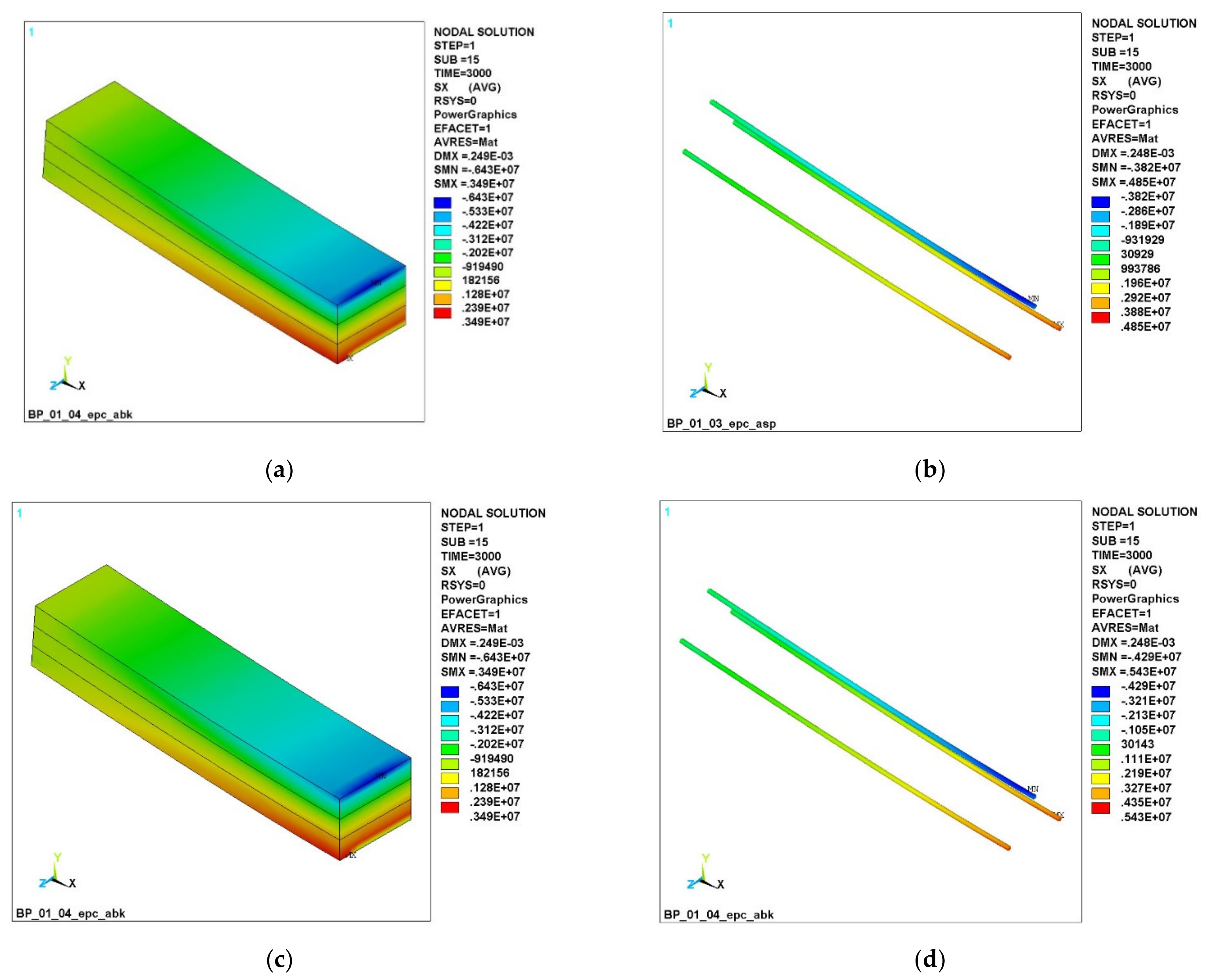
3.1. Numerical Simulation of the Operation of Variotropic Bending Elements Reinforced with Polymer Composite Reinforcement in Physically Linear and Nonlinear Formulations
3.2. Discussion
4. Conclusions
- (1)
- Numerical models of lintel beams of non-variotropic and variotropic structures with various types of reinforcement, made in a spatial formulation by physically linear and non-linear elements, have been developed. The stress-strain state of the concrete of lintel beams and polymer composite reinforcing bars of all considered types was studied.
- (2)
- It has been established that, in a physically nonlinear setting, when using the integral characteristics of concrete, the deformability (deflections) of the elements is greater than that when using the differential characteristics of concrete along the height of the section (up to 5%). This trend is similar for all bending elements, regardless of the type of polymer composite reinforcement used.
- (3)
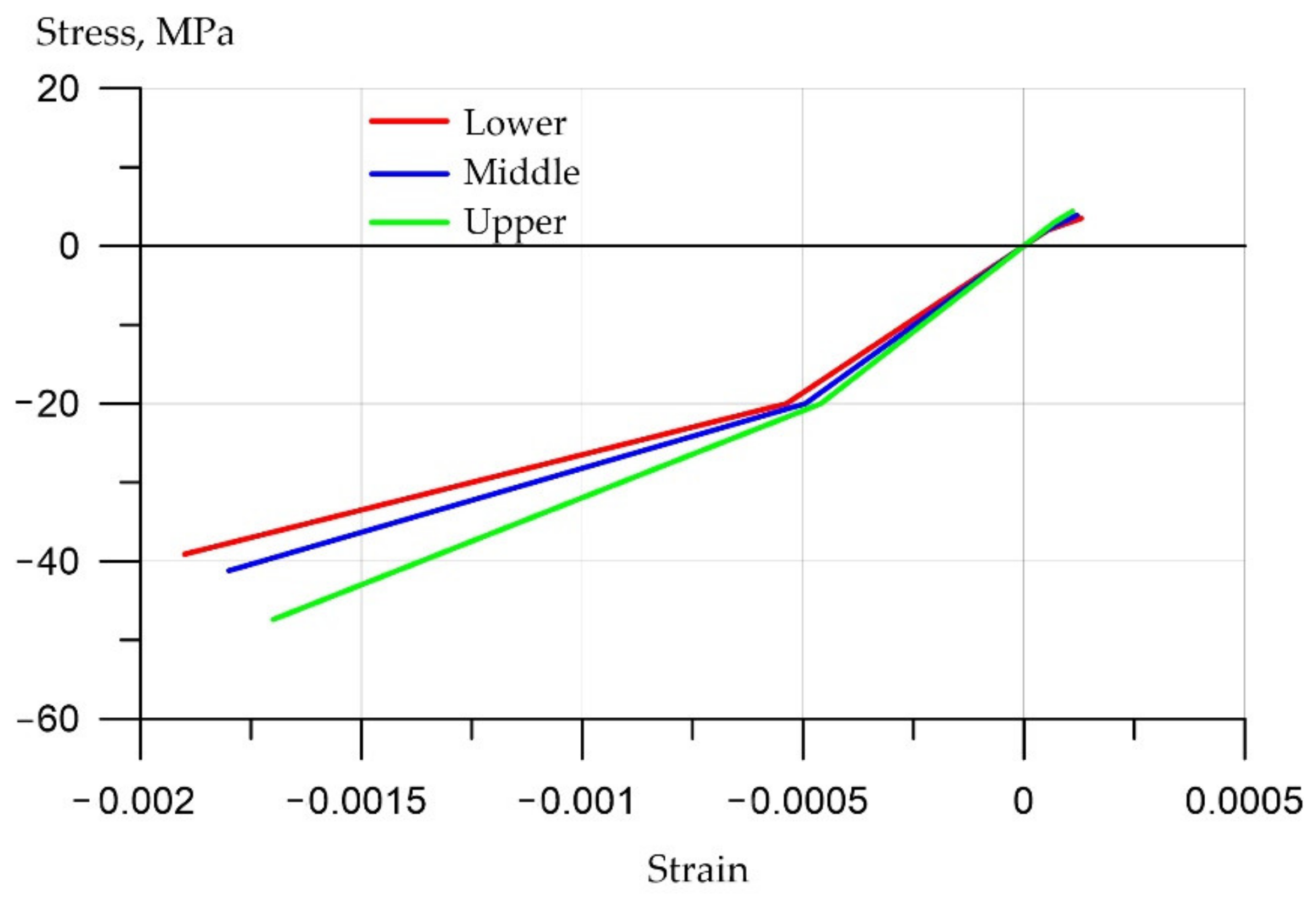
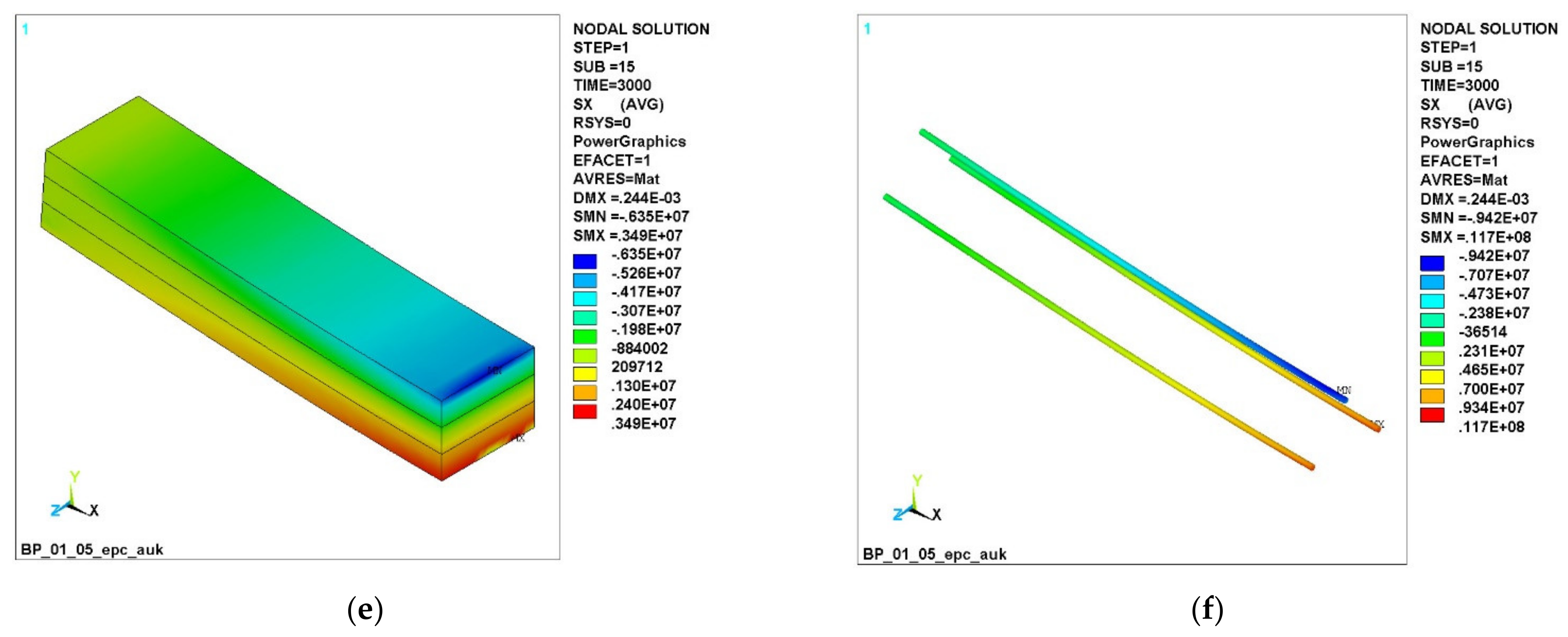
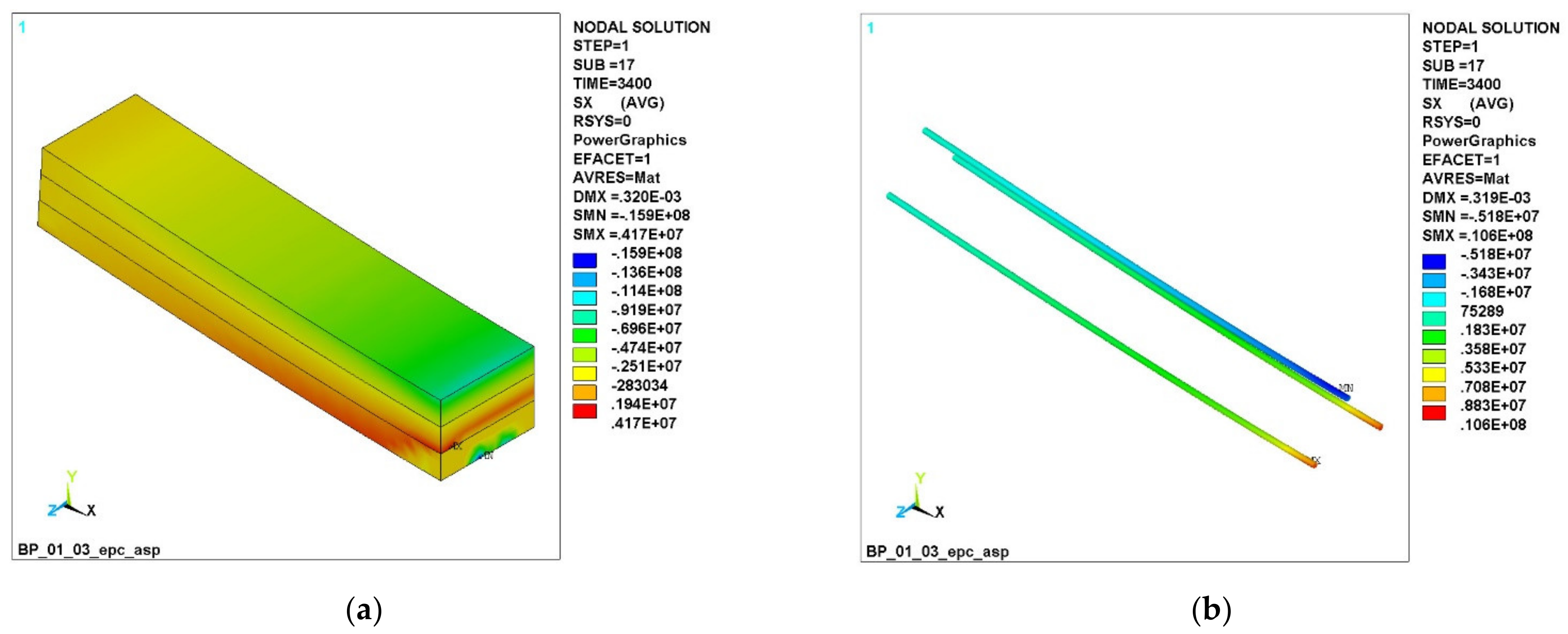
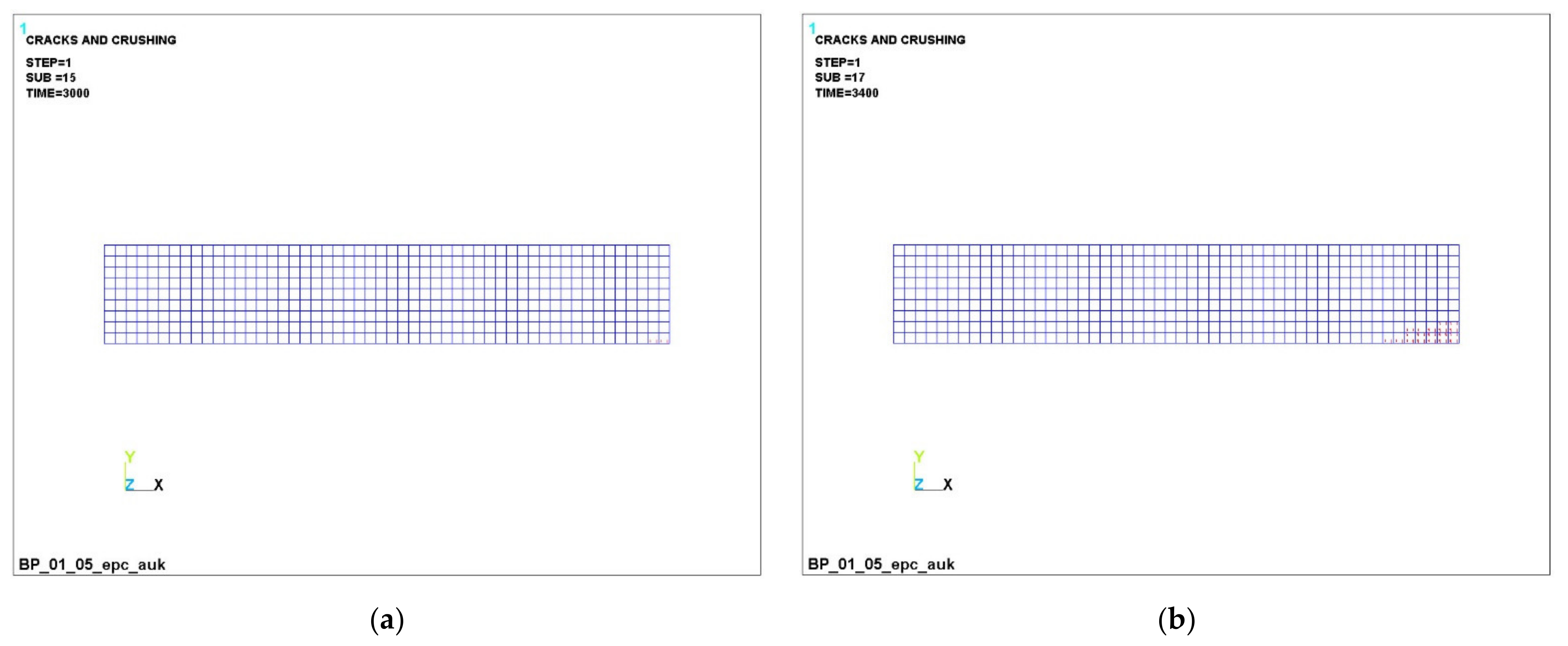
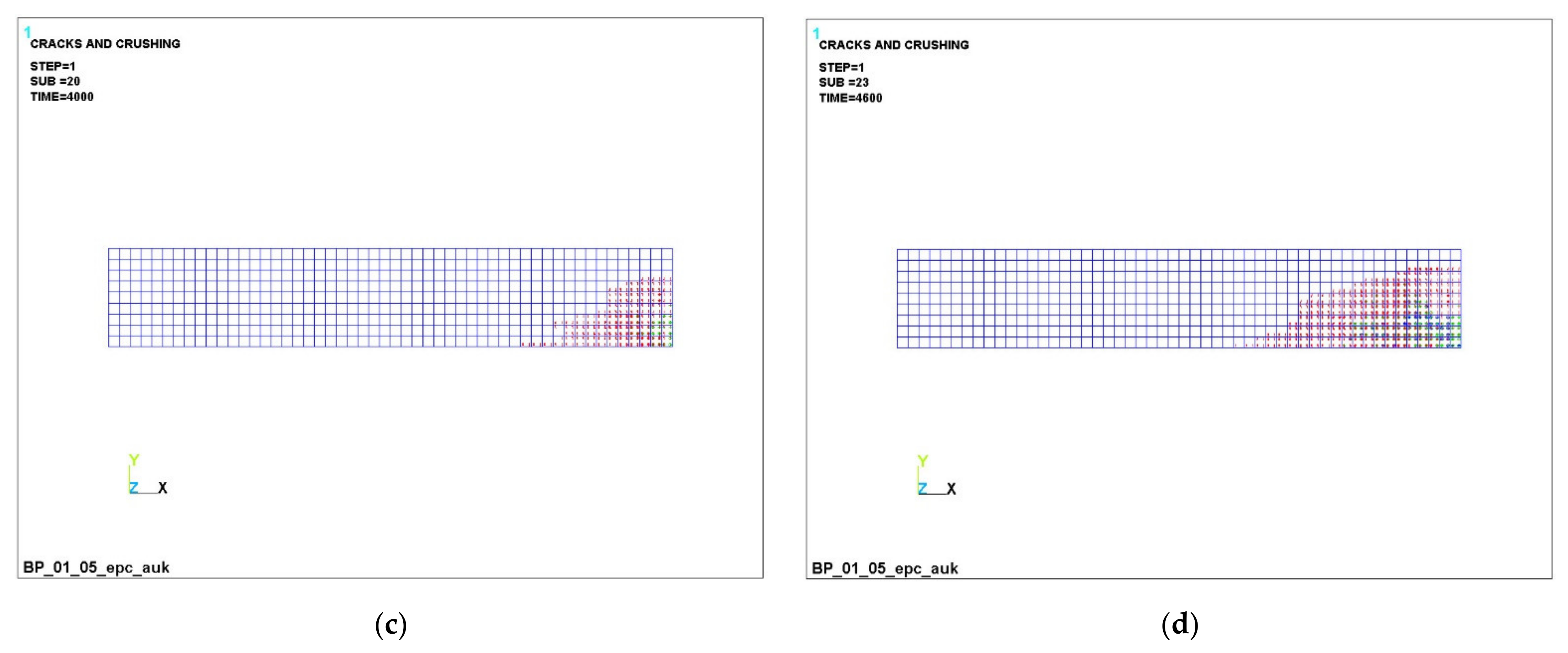
- In the upper, most compressed zone, an increase in the compressive strength of concrete is required, and in the tensile zone, concrete practically does not work. Concrete transfers all forces to the reinforcement in the central zone in the middle of the beam at the bottom edge. In this case, the effect of a clear redistribution of stresses is in favor of elements with a variotropic cross section in height. The compressed fibers in the uppermost zone are most susceptible to anodizing, i.e., the highest strength. The height of the compressed zone of concrete is in this zone, where the work of the structure is most effective.
- (4)
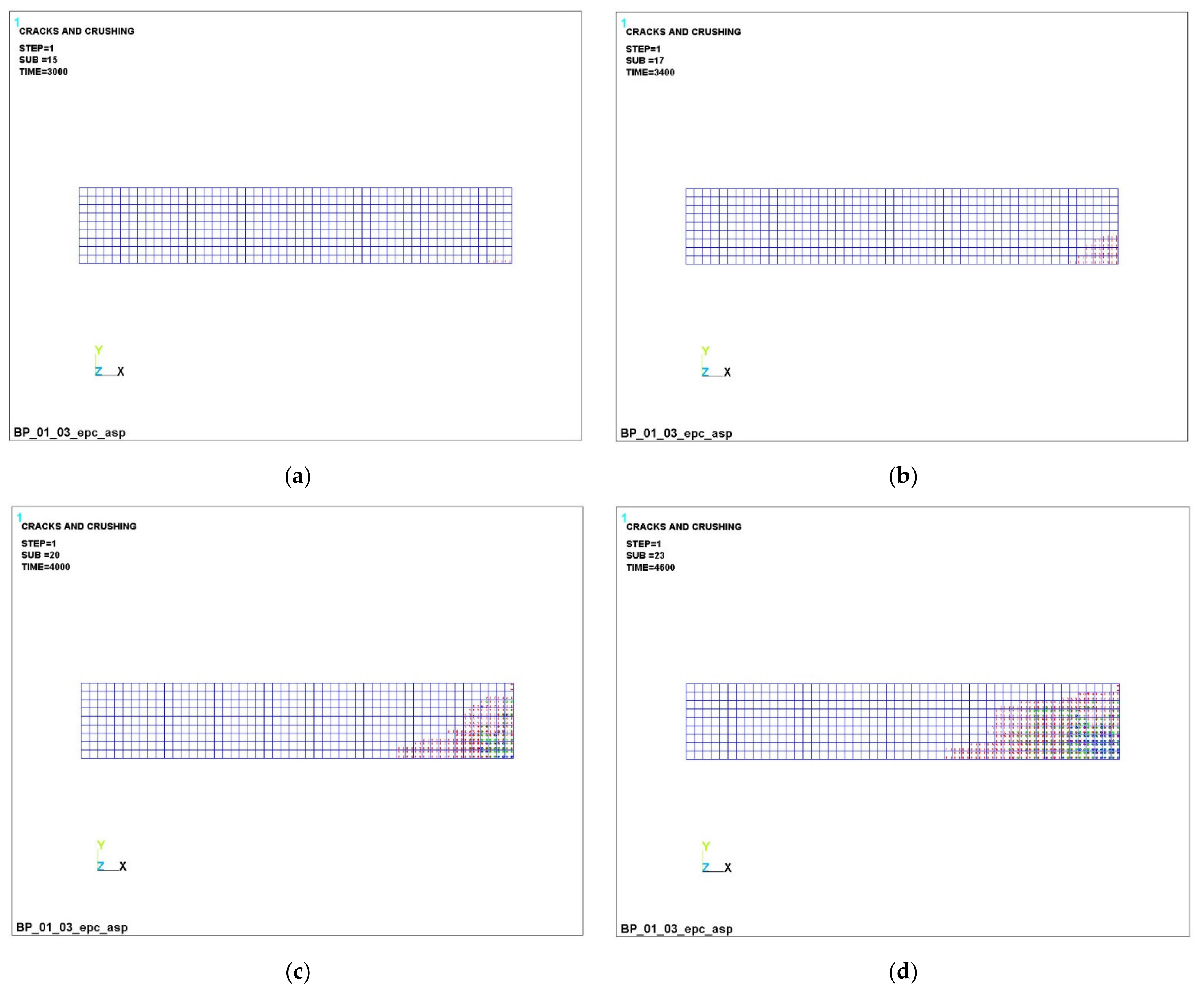
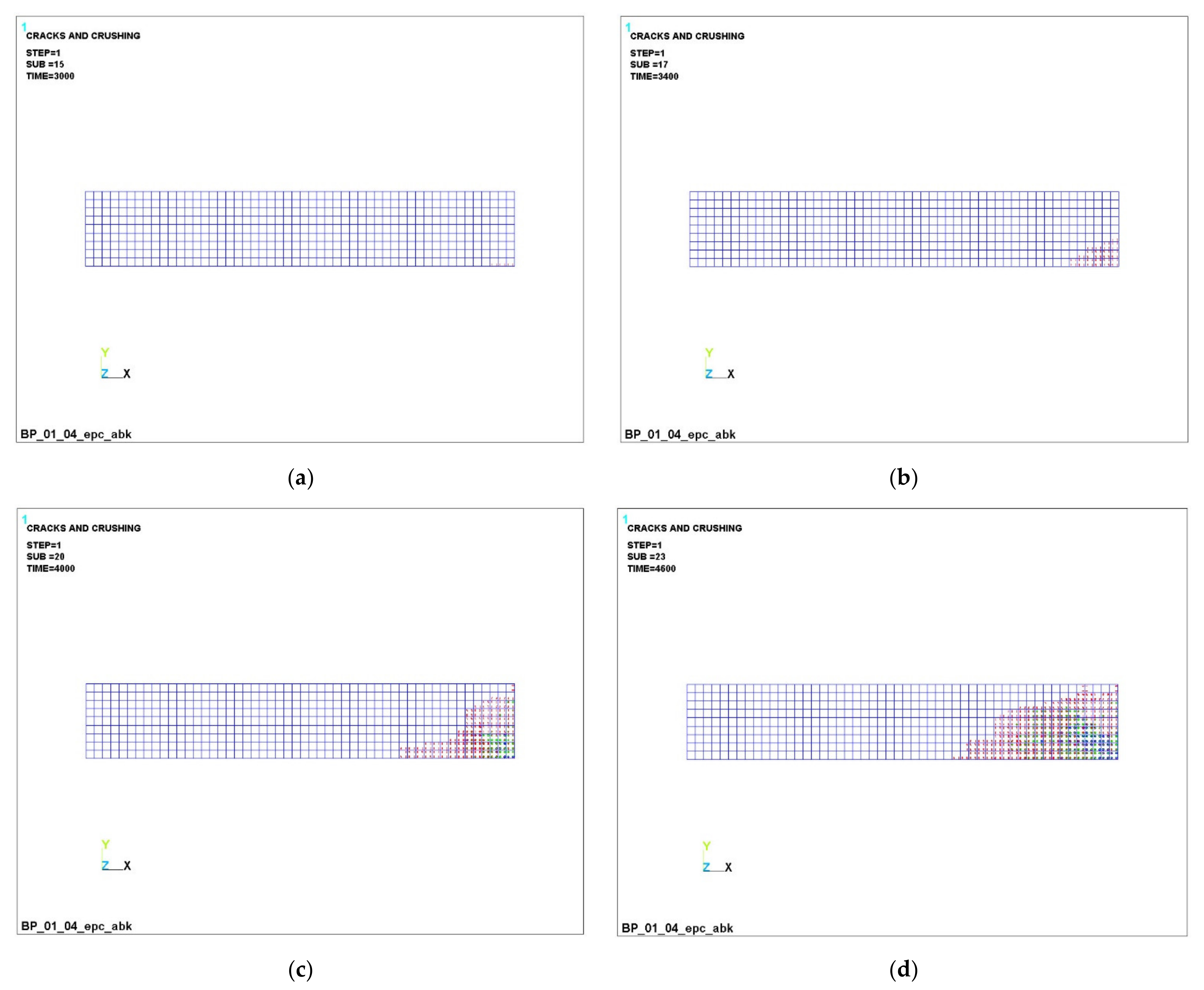
- It has been established that, in variotropic bending elements, carbon fiber reinforcement works most adequately under conditions of active cracking; however, stresses there also grow quite strongly, and there is still a risk of uncontrolled deformations, despite the fact that deformations occur two times less frequently than those of fiberglass. It is confirmed that fiberglass and basalt rebar materials are very ambiguous. When they are used in design and construction, it is necessary to clearly monitor the process of cracking, the process of deformation and the process of stress growth.
Author Contributions
Funding
Institutional Review Board Statement
Informed Consent Statement
Data Availability Statement
Acknowledgments
Conflicts of Interest
References
- Shubaili, M.; Elawadi, A.; Orton, S.; Tian, Y. Time-Dependent Behavior of Reinforced Concrete Beams under High Sustained Loads. Appl. Sci. 2022, 12, 4015. [Google Scholar] [CrossRef]
- Lechman, M. Cross-Sectional Analysis of the Resistance of RC Members Subjected to Bending with/without Axial Force. Materials 2022, 15, 1957. [Google Scholar] [CrossRef] [PubMed]
- Hong, K.-N.; Yeon, Y.-M.; Ji, S.-W.; Lee, S. Flexural Behavior of RC Beams Using Fe-Based Shape Memory Alloy Rebars as Tensile Reinforcement. Buildings 2022, 12, 190. [Google Scholar] [CrossRef]
- Ro, K.M.; Kim, M.S.; Cho, C.G.; Lee, Y.H. Structural Performance of a Precast Concrete Modular Beam Using Bolted Connecting Plates. Appl. Sci. 2021, 11, 12110. [Google Scholar] [CrossRef]
- Korolev, A.S.; Kopp, A.; Odnoburcev, D.; Loskov, V.; Shimanovsky, P.; Koroleva, Y.; Vatin, N.I. Compressive and Tensile Elastic Properties of Concrete: Empirical Factors in Span Reinforced Structures Design. Materials 2021, 14, 7578. [Google Scholar] [CrossRef]
- Sharaky, I.A.; Elamary, A.S.; Alharthi, Y.M. Flexural Response and Failure Analysis of Solid and Hollow Core Concrete Beams with Additional Opening at Different Locations. Materials 2021, 14, 7203. [Google Scholar] [CrossRef]
- Bywalski, C.; Drzazga, M.; Kamiński, M.; Kaźmierowski, M. A New Proposal for the Shear Strength Prediction of Beams Longitudinally Reinforced with Fiber-Reinforced Polymer Bars. Buildings 2020, 10, 86. [Google Scholar] [CrossRef]
- Adam, M.A.; Erfan, A.M.; Habib, F.A.; El-Sayed, T.A. Structural Behavior of High-Strength Concrete Slabs Reinforced with GFRP Bars. Polymers 2021, 13, 2997. [Google Scholar] [CrossRef]
- Li, G.; Zhao, J.; Wang, Z. Fatigue Behavior of Glass Fiber-Reinforced Polymer Bars after Elevated Temperatures Exposure. Materials 2018, 11, 1028. [Google Scholar] [CrossRef] [Green Version]
- Bywalski, C.; Drzazga, M.; Kaźmierowski, M.; Kamiński, M. Shear Behavior of Concrete Beams Reinforced with a New Type of Glass Fiber Reinforced Polymer Reinforcement: Experimental Study. Materials 2020, 13, 1159. [Google Scholar] [CrossRef] [Green Version]
- Ye, Y.-Y.; Zeng, J.-J.; Li, P.-L. A State-of-the-Art Review of FRP-Confined Steel-Reinforced Concrete (FCSRC) Structural Members. Polymers 2022, 14, 677. [Google Scholar] [CrossRef]
- Zhou, Y.; Weng, Y.; Li, L.; Hu, B.; Huang, X.; Zhu, Z. Recycled GFRP Aggregate Concrete Considering Aggregate Grading: Compressive Behavior and Stress–Strain Modeling. Polymers 2022, 14, 581. [Google Scholar] [CrossRef]
- Elgabbas, F.; Vincent, P.; Ahmed, E.A.; Benmokrane, B. Experimental testing of basalt-fiber-reinforced polymer bars in concrete beams. Compos. Part B Eng. 2016, 91, 205–218. [Google Scholar] [CrossRef]
- Ellis, D.S.; Tabatabai, H.; Nabizadeh, A. Residual Tensile Strength and Bond Properties of GFRP Bars after Exposure to Elevated Temperatures. Materials 2018, 11, 346. [Google Scholar] [CrossRef] [Green Version]
- Urbanski, M.; Lapko, A.; Garbacz, A. Investigation on Concrete Beams Reinforced with Basalt Rebars as an Effective Alternative of Conventional R/C Structures. Procedia Eng. 2013, 57, 1183–1191. [Google Scholar] [CrossRef] [Green Version]
- Yang, K.-H.; Mun, J.-H. Cyclic Flexural and Shear Performances of Beam Elements with Longitudinal Glass Fiber Reinforced Polymer (GFRP) Bars in Exterior Beam-Column Connections. Appl. Sci. 2018, 8, 2353. [Google Scholar] [CrossRef] [Green Version]
- Chin, W.J.; Park, Y.H.; Cho, J.-R.; Lee, J.-Y.; Yoon, Y.-S. Flexural Behavior of a Precast Concrete Deck Connected with Headed GFRP Rebars and UHPC. Materials 2020, 13, 604. [Google Scholar] [CrossRef] [Green Version]
- Jumaa, G.B.; Yousif, A.R. Size effect on the shear failure of high-strength concrete beams reinforced with basalt FRP bars and stirrups. Constr. Build. Mater. 2019, 209, 77–94. [Google Scholar] [CrossRef]
- Bellakehal, H.; Zaidi, A.; Masmoudi, R.; Bouhicha, M. Behavior of FRP Bars-Reinforced Concrete Slabs under Temperature and Sustained Load Effects. Polymers 2014, 6, 873–889. [Google Scholar] [CrossRef] [Green Version]
- Sun, Y.; Liu, Y.; Wu, T.; Liu, X.; Lu, H. Numerical Analysis on Flexural Behavior of Steel Fiber-Reinforced LWAC Beams Reinforced with GFRP Bars. Appl. Sci. 2019, 9, 5128. [Google Scholar] [CrossRef] [Green Version]
- Pavlović, A.; Donchev, T.; Petkova, D.; Staletović, N. Sustainability of alternative reinforcement for concrete structures: Life cycle assessment of basalt FRP bars. Constr. Build. Mater. 2022, 334, 127424. [Google Scholar] [CrossRef]
- Stoiber, N.; Hammerl, M.; Kromoser, B. Cradle-to-gate life cycle assessment of CFRP reinforcement for concrete structures: Calculation basis and exemplary application. J. Clean. Prod. 2021, 280, 124300. [Google Scholar] [CrossRef]
- Ashour, A.F. Flexural and shear capacities of concrete beams reinforced with GFRP bars. Constr. Build. Mater. 2006, 20, 1005–1015. [Google Scholar] [CrossRef]
- Rogowski, J.; Kotynia, R. Comparison of Prestressing Methods with CFRP and SMA Materials in Flexurally Strengthened RC Members. Materials 2022, 15, 1231. [Google Scholar] [CrossRef]
- Jin, Q.; Chen, P.; Gao, Y.; Du, A.; Liu, D.; Sun, L. Tensile Strength and Degradation of GFRP Bars under Combined Effects of Mechanical Load and Alkaline Solution. Materials 2020, 13, 3533. [Google Scholar] [CrossRef]
- Elgabbas, F.; Ahmed, E.A.; Benmokrane, B. Physical and mechanical characteristics of new basalt-FRP bars for reinforcing concrete structures. Constr. Build. Mater. 2015, 95, 623–635. [Google Scholar] [CrossRef]
- Serbescu, A.; Guadagnini, M.; Kypros, P. Mechanical Characterization of Basalt FRP Rebars and Long-Term Strength Predictive Model. J. Compos. Constr. 2022, 19, 04014037. [Google Scholar] [CrossRef]
- Lapko, A.; Urbański, M. Experimental and theoretical analysis of deflections of concrete beams reinforced with basalt rebar. Archiv. Civ. Mech. Eng. 2015, 15, 223–230. [Google Scholar] [CrossRef]
- Tomlinson, D.; Fam, A. Performance of Concrete Beams Reinforced with Basalt FRP for Flexure and Shear. J. Compos. Constr. 2015, 19, 04014036. [Google Scholar] [CrossRef]
- Oller, E.; Marí, A.; Bairán, J.M.; Cladera, A. Shear design of reinforced concrete beams with FRP longitudinal and transverse reinforcement. Compos. Part B Eng. 2015, 74, 104–122. [Google Scholar] [CrossRef] [Green Version]
- Ostrowski, K.A.; Chastre, C.; Furtak, K.; Malazdrewicz, S. Consideration of Critical Parameters for Improving the Efficiency of Concrete Structures Reinforced with FRP. Materials 2022, 15, 2774. [Google Scholar] [CrossRef] [PubMed]
- Qureshi, J. A Review of Fibre Reinforced Polymer Structures. Fibers 2022, 10, 27. [Google Scholar] [CrossRef]
- Duda, S.; Lesiuk, G.; Zielonka, P.; Stabla, P.; Lubecki, M.; Ziółkowski, G. Flexural Pseudo-Ductility Effect in Hybrid GFRP/CFRP Bars under Static Loading Conditions. Materials 2021, 14, 5608. [Google Scholar] [CrossRef] [PubMed]
- Deng, A.; Cao, M.; Lu, Q.; Xu, W. Identification of Multiple Cracks in Composite Laminated Beams Using Perturbation to Dynamic Equilibrium. Sensors 2021, 21, 6171. [Google Scholar] [CrossRef] [PubMed]
- Ahmed, H.; Hussain, G.; Gohar, S.; Ali, A.; Alkahtani, M. Impact Toughness of Hybrid Carbon Fiber-PLA/ABS Laminar Composite Produced through Fused Filament Fabrication. Polymers 2021, 13, 3057. [Google Scholar] [CrossRef]
- Ma, L.; Liu, F.; Liu, D.; Liu, Y. Review of Strain Rate Effects of Fiber-Reinforced Polymer Composites. Polymers 2021, 13, 2839. [Google Scholar] [CrossRef]
- Lu, J.; Qi, Y.; Li, Y.; Wang, X. Axial Compressive Performance of a Composite Concrete-Filled GFRP Tube Square Column. Appl. Sci. 2021, 11, 6757. [Google Scholar] [CrossRef]
- Katouzian, M.; Vlase, S.; Scutaru, M.L. Finite Element Method-Based Simulation Creep Behavior of Viscoelastic Carbon-Fiber Composite. Polymers 2021, 13, 1017. [Google Scholar] [CrossRef]
- Katouzian, M.; Vlase, S. Creep Response of Carbon-Fiber-Reinforced Composite Using Homogenization Method. Polymers 2021, 13, 867. [Google Scholar] [CrossRef]
- Amini Pishro, A.; Zhang, S.; Zhang, Z.; Zhao, Y.; Amini Pishro, M.; Zhang, L.; Yang, Q.; Postel, V. Structural Behavior of FRP-Retrofitted RC Beams under Combined Torsion and Bending. Materials 2022, 15, 3213. [Google Scholar] [CrossRef]
- Singh, A.; Charak, A.; Biligiri, K.P.; Pandurangan, V. Glass and carbon fiber reinforced polymer composite wastes in pervious concrete: Material characterization and lifecycle assessment. Resour. Conserv. Recycl. 2022, 182, 106304. [Google Scholar] [CrossRef]
- Kormanikova, E.; Zmindak, M.; Novak, P.; Sabol, P. Tensile properties of carbon fiber reinforced polymer matrix composites: Application for the strengthening of reinforced concrete structure. Compos. Struct. 2021, 275, 114448. [Google Scholar] [CrossRef]
- Sirisonthi, A.; Julphunthong, P.; Joyklad, P.; Suparp, S.; Ali, N.; Javid, M.A.; Chaiyasarn, K.; Hussain, Q. Structural Behavior of Large-Scale Hollow Section RC Beams and Strength Enhancement Using Carbon Fiber Reinforced Polymer (CFRP) Composites. Polymers 2022, 14, 158. [Google Scholar] [CrossRef]
- Ge, W.; Tang, R.; Wang, Y.; Zhang, Z.; Sun, C.; Yao, S.; Lu, W. Flexural performance of ECC-concrete composite beams strengthened with carbon fiber sheet. Results Eng. 2022, 13, 100334. [Google Scholar] [CrossRef]
- Krall, M.; Polak, M.A. Concrete beams with different arrangements of GFRP flexural and shear reinforcement. Eng. Struct. 2019, 198, 109333. [Google Scholar] [CrossRef]
- Issa, M.A.; Ovitigala, T.; Ibrahim, M. Shear Behavior of Basalt Fiber Reinforced Concrete Beams with and without Basalt FRP Stirrups. J. Compos. Constr. 2016, 20, 04015083. [Google Scholar] [CrossRef]
- Hawileh, R.A.; Abdalla, J.A.; Hasan, S.S.; Ziyada, M.B.; Abu-Obeidah, A. Models for predicting elastic modulus and tensile strength of carbon, basalt and hybrid carbon-basalt FRP laminates at elevated temperatures. Constr. Build. Mater. 2016, 114, 364–373. [Google Scholar] [CrossRef]
- Jumaa, G.B.; Yousif, A.R. Size Effect in Shear Failure of High Strength Concrete Beams without Stirrup reinforced with Basalt FRP Bars. KSCE J. Civ. Eng. 2019, 23, 1636–1650. [Google Scholar] [CrossRef]
- Abdel-Jaber, M.; Abdel-Jaber, M.; Katkhuda, H.; Shatarat, N.; El-Nimri, R. Influence of Compressive Strength of Concrete on Shear Strengthening of Reinforced Concrete Beams with Near Surface Mounted Carbon Fiber-Reinforced Polymer. Buildings 2021, 11, 563. [Google Scholar] [CrossRef]
- Zhou, B.; Wu, R.-Y.; Liu, Y.; Zhang, X.; Yin, S. Flexural Strength Design of Hybrid FRP-Steel Reinforced Concrete Beams. Materials 2021, 14, 6400. [Google Scholar] [CrossRef]
- Pang, M.; Shi, S.; Hu, H.; Lou, T. Flexural Behavior of Two-Span Continuous CFRP RC Beams. Materials 2021, 14, 6746. [Google Scholar] [CrossRef]
- Yuan, J.; Gao, D.; Zhang, Y.; Zhu, H. Improving Ductility for Composite Beams Reinforced with GFRP Tubes by Using Rebars/Steel Angles. Polymers 2022, 14, 551. [Google Scholar] [CrossRef]
- Scholzen, A.; Chudoba, R.; Hegger, J. Dünnwandiges Schalentragwerk aus textilbewehrtem Beton. Beton-Und Stahlbetonbau 2012, 107, 767–776. [Google Scholar] [CrossRef]
- Curbach, M.; Graf, W.; Jesse, D.; Sickert, J.-U.; Weiland, S. Segmentbrücke aus textilbewehrtem Beton: Konstruktion, Fertigung, numerische Berechnung. Beton-Und Stahlbetonbau 2007, 102, 342–352. [Google Scholar] [CrossRef]
- Mechtcherine, V.; Michel, A.; Liebscher, M.; Schneider, K.; Großmann, C. Mineral-impregnated carbon fiber composites as novel reinforcement for concrete construction: Material and automation perspectives. Autom. Constr. 2020, 110, 103002. [Google Scholar] [CrossRef]
- Thamrin, R.; Zaidir, Z.; Iwanda, D. Ductility Estimation for Flexural Concrete Beams Longitudinally Reinforced with Hybrid FRP–Steel Bars. Polymers 2022, 14, 1017. [Google Scholar] [CrossRef]
- Zheng, Y.-Z.; Wang, W.-W.; Mosalam, K.M.; Fang, Q.; Chen, L.; Zhu, Z.-F. Experimental investigation and numerical analysis of RC beams shear strengthened with FRP/ECC composite layer. Compos. Struct. 2020, 246, 112436. [Google Scholar] [CrossRef]
- Rahimi, H.; Hutchinson, A. Concrete Beams Strengthened with Externally Bonded FRP Plates. J. Compos. Constr. 2001, 5, 44–56. [Google Scholar] [CrossRef]
- Norris, T.; Saadatmanesh, H.; Ehsani, M.R. Shear and Flexural Strengthening of R/C Beams with Carbon Fiber Sheets. J. Struct. Eng. 1997, 123, 903–911. [Google Scholar] [CrossRef]
- Li, C.; Guo, R.; Xian, G.; Li, H. Innovative compound-type anchorage system for a large-diameter pultruded carbon/glass hybrid rod for bridge cable. Mater. Struct. 2020, 53, 73. [Google Scholar] [CrossRef]
- Blaznov, A.N.; Atyasova, E.V.; Shundrina, I.K.; Samoilenko, V.V.; Firsov, V.V.; Zubkov, A.S. Thermomechanical characterization of BFRP and GFRP with different degree of conversion. Polym. Test. 2017, 60, 49–57. [Google Scholar] [CrossRef]
- Li, C.; Yin, X.; Wang, Y.; Zhang, L.; Zhang, Z.; Liu, Y.; Xian, G. Mechanical property evolution and service life prediction of pultruded carbon/glass hybrid rod exposed in harsh oil-well condition. Compos. Struct. 2020, 246, 112418. [Google Scholar] [CrossRef]
- Mailyan, L.R.; Stel’makh, S.A.; Shcherban’, E.M.; Khalyushev, A.K.; Smolyanichenko, A.S.; Sysoev, A.K.; Parinov, I.A.; Cherpakov, A.V. Investigation of Integral and Differential Characteristics of Variatropic Structure Heavy Concretes by Ultrasonic Methods. Appl. Sci. 2021, 11, 3591. [Google Scholar] [CrossRef]
- Stel’makh, S.A.; Shcherban’, E.M.; Beskopylny, A.N.; Mailyan, L.R.; Meskhi, B.; Butko, D.; Smolyanichenko, A.S. Influence of Composition and Technological Factors on Variatropic Efficiency and Constructive Quality Coefficients of Lightweight Vibro-Centrifuged Concrete with Alkalized Mixing Water. Appl. Sci. 2021, 11, 9293. [Google Scholar] [CrossRef]
- Shcherban’, E.M.; Stel’makh, S.A.; Beskopylny, A.; Mailyan, L.R.; Meskhi, B. Influence of Mechanochemical Activation of Concrete Components on the Properties of Vibro-Centrifugated Heavy Concrete. Appl. Sci. 2021, 11, 10647. [Google Scholar] [CrossRef]
- Beskopylny, A.N.; Stel’makh, S.A.; Shcherban’, E.M.; Mailyan, L.R.; Meskhi, B. Nano modifying additive micro silica influence on integral and differential characteristics of vibrocentrifuged concrete. J. Build. Eng. 2022, 51, 104235. [Google Scholar] [CrossRef]
- Mailyan, L.R.; Stel’makh, S.A.; Shcherban, E.M. Differential characteristics of concrete in centrifugally spun and vibrospun building structures. Mag. Civ. Eng. 2022, 108, 10812. [Google Scholar] [CrossRef]
- Stel’makh, S.A.; Shcherban’, E.M.; Beskopylny, A.; Mailyan, L.R.; Meskhi, B.; Varavka, V. Quantitative and Qualitative Aspects of Composite Action of Concrete and Dispersion-Reinforcing Fiber. Polymers 2022, 14, 682. [Google Scholar] [CrossRef]
- Beskopylny, A.N.; Stel’makh, S.A.; Shcherban’, E.M.; Mailyan, L.R.; Meskhi, B.; Efremenko, I.; Varavka, V.; Beskopylny, N.; Dotsenko, N. Modeling and Experimental Verification of the Performance of Polymer Composite Reinforcing Bars of Different Types in Concrete of Different Density. Polymers 2022, 14, 1756. [Google Scholar] [CrossRef]
- Stel’makh, S.A.; Shcherban’, E.M.; Beskopylny, A.; Mailyan, L.R.; Meskhi, B.; Dotsenko, N. Enchainment of the Coefficient of Structural Quality of Elements in Compression and Bending by Combined Reinforcement of Concrete with Polymer Composite Bars and Dispersed Fiber. Polymers 2021, 13, 4347. [Google Scholar] [CrossRef]
- Beskopylny, A.N.; Stel’makh, S.A.; Shcherban’, E.M.; Mailyan, L.R.; Meskhi, B.; El’shaeva, D.; Varavka, V. Developing Environmentally Sustainable and Cost-Effective Geopolymer Concrete with Improved Characteristics. Sustainability 2021, 13, 13607. [Google Scholar] [CrossRef]
- Shcherban’, E.M.; Stel’makh, S.A.; Beskopylny, A.; Mailyan, L.R.; Meskhi, B.; Shuyskiy, A. Improvement of Strength and Strain Characteristics of Lightweight Fiber Concrete by Electromagnetic Activation in a Vortex Layer Apparatus. Appl. Sci. 2022, 12, 104. [Google Scholar] [CrossRef]
- Beskopylny, A.N.; Shcherban’, E.M.; Stel’makh, S.A.; Mailyan, L.R.; Meskhi, B.; El’shaeva, D. The Influence of Composition and Recipe Dosage on the Strength Characteristics of New Geopolymer Concrete with the Use of Stone Flour. Appl. Sci. 2022, 12, 613. [Google Scholar] [CrossRef]
- Shcherban’, E.M.; Stel’makh, S.A.; Beskopylny, A.; Mailyan, L.R.; Meskhi, B. Increasing the Corrosion Resistance and Durability of Geopolymer Concrete Structures of Agricultural Buildings Operating in Specific Conditions of Aggressive Environments of Livestock Buildings. Appl. Sci. 2022, 12, 1655. [Google Scholar] [CrossRef]
- SP 52-101-2003 Concrete and Reinforced Concrete Structures without Prestressing. Available online: https://docs.cntd.ru/document/1200037361 (accessed on 16 May 2022).
- SP 63.13330.2018 Concrete and Reinforced Concrete Structures. General Provisions. Available online: https://docs.cntd.ru/document/554403082 (accessed on 16 May 2022).
- Gilman, E.D. Certificate of Authorship 463654 Russian Federation, C 04b 41/30 Rostov-on-Don. RISI. N 1903597/29-33; Declared 11.04.73; publ. 15.03.75, bull. N 10. 1p. Available online: https://patents.su/1-463654-sposob-izgotovleniya-betonnykh-i-zhelezobetonnykh-izdelijj.html (accessed on 16 May 2022).
- Gilman, E.D. Certificate of Authorship 612915 Russian Federation, C 04B 41/30 Rostov-on-Don. RISI. N 1948308/29-33; Declared 17.07.73; publ. 30.06.78, bull. N 24. 2p. Available online: https://patents.su/2-612915-sposob-izgotovleniya-betonnykh-i-zhelezobetonnykh-izdelijj.html (accessed on 16 May 2022).


| Characteristics | Reinforcement Type | ||
|---|---|---|---|
| GCR | BCR | CCR | |
| Tensile strength, MPa | 1236 | 1350 | 1528 |
| Tensile modulus, GPa | 56 | 63 | 140 |
| Compressive strength, MPa | 523 | 500 | 979 |
| Relative extension, % | 1.6 | 1.7 | 1.3 |
| The nature of the behavior under load (dependence “stress-strain”) | Linear | ||
| Density, kg/m³ | 1943 | 1900 | 1993 |
| Number | Title | Characteristics |
|---|---|---|
| 1 | Lower layer | Modulus of elasticity: 3.721 × 10¹⁰ Pa Poisson’s ratio: 0.2 Tensile elasticity: 2002.6 kPa Tensile strength: 3500.0 kPa Limit relative deformation tensile: 0.00013 Compressive elasticity: 20,000 kPa Compressive strength: 39,100 kPa Limit relative deformation for compression: 0.0019 Tensile hardening modulus: 1.966 × 10¹⁰ Pa Compressive hardening modulus: 1.402 × 10¹⁰ Pa |
| 2 | Middle layer | Modulus of elasticity: 4.0408 × 10¹⁰ Pa Poisson’s ratio: 0.2 Tensile elasticity: 2002.6 kPa Tensile strength: 3900.0 kPa Limit relative deformation tensile: 0.00012 Compressive elasticity: 20,000 kPa Compressive strength: 41,200 kPa Limit relative deformation for compression: 0.0018 Tensile hardening modulus: 2.69 × 10¹⁰ Pa Compressive hardening modulus: 1.62 × 10¹⁰ Pa |
| 3 | Upper layer | Modulus of elasticity: 4.3508 × 10¹⁰ Pa Poisson’s ratio: 0.2 Tensile elasticity: 3002.6 kPa Tensile strength: 4400.0 kPa Limit relative deformation tensile: 0.00011 Compressive elasticity: 20,000 kPa Compressive strength: 47,400 kPa Limit relative deformation for compression: 0.0017 Tensile hardening modulus: 3.41 × 10¹⁰ Pa Compressive hardening modulus: 2.21 × 10¹⁰ Pa |
| 4 | Glass composite (GCR) | Modulus of elasticity: 5.6 × 10¹⁰ Pa Poisson’s ratio: 0.32 |
| 4 | Basalt composite (BCR) | Modulus of elasticity: 6.3 × 10¹⁰ Pa Poisson’s ratio: 0.32 |
| 4 | Carbon composite (CCR) | Modulus of elasticity: 1.4 × 10¹¹ Pa Poisson’s ratio: 0.32 |
Publisher’s Note: MDPI stays neutral with regard to jurisdictional claims in published maps and institutional affiliations. |
© 2022 by the authors. Licensee MDPI, Basel, Switzerland. This article is an open access article distributed under the terms and conditions of the Creative Commons Attribution (CC BY) license (https://creativecommons.org/licenses/by/4.0/).
Share and Cite
Beskopylny, A.N.; Meskhi, B.; Stel’makh, S.A.; Shcherban’, E.M.; Mailyan, L.R.; Veremeenko, A.; Akopyan, V.; Shilov, A.V.; Chernil’nik, A.; Beskopylny, N. Numerical Simulation of the Bearing Capacity of Variotropic Short Concrete Beams Reinforced with Polymer Composite Reinforcing Bars. Polymers 2022, 14, 3051. https://doi.org/10.3390/polym14153051
Beskopylny AN, Meskhi B, Stel’makh SA, Shcherban’ EM, Mailyan LR, Veremeenko A, Akopyan V, Shilov AV, Chernil’nik A, Beskopylny N. Numerical Simulation of the Bearing Capacity of Variotropic Short Concrete Beams Reinforced with Polymer Composite Reinforcing Bars. Polymers. 2022; 14(15):3051. https://doi.org/10.3390/polym14153051
Chicago/Turabian StyleBeskopylny, Alexey N., Besarion Meskhi, Sergey A. Stel’makh, Evgenii M. Shcherban’, Levon R. Mailyan, Andrey Veremeenko, Vladimir Akopyan, Aleksandr V. Shilov, Andrei Chernil’nik, and Nikita Beskopylny. 2022. "Numerical Simulation of the Bearing Capacity of Variotropic Short Concrete Beams Reinforced with Polymer Composite Reinforcing Bars" Polymers 14, no. 15: 3051. https://doi.org/10.3390/polym14153051
APA StyleBeskopylny, A. N., Meskhi, B., Stel’makh, S. A., Shcherban’, E. M., Mailyan, L. R., Veremeenko, A., Akopyan, V., Shilov, A. V., Chernil’nik, A., & Beskopylny, N. (2022). Numerical Simulation of the Bearing Capacity of Variotropic Short Concrete Beams Reinforced with Polymer Composite Reinforcing Bars. Polymers, 14(15), 3051. https://doi.org/10.3390/polym14153051