This section describes the methods used in the study of the electrophysical and magnetic properties of RAM materials and also presents the results of the research:
4.3. Investigation of the Properties of Composite Materials Using a Measuring Line
The dielectric permittivity measurement by means of the closed-loop line method is based on observing the pattern of standing waves in the waveguide path containing the sample under study (
Figure 11).
This method is most common when measuring the dielectric properties of materials since, in comparison with other methods in many practical cases it turns out to be relatively simpler and more universal in terms of the technique of preparing and conducting the experiment. Its disadvantage should include more cumbersome calculations to obtain the final results. The test sample of the material is placed in a segment of a rectangular waveguide attached to the measuring line. The sample must completely fill the section of the waveguide and fit snugly to the short-circuiting flange. In principle, the length of the sample can be arbitrary [
160].
The measurements were carried out in the frequency band 20–53 GHz. This range was overlapped by three bands. For each band, special standard measuring equipment is used (
Table 6) [
129].
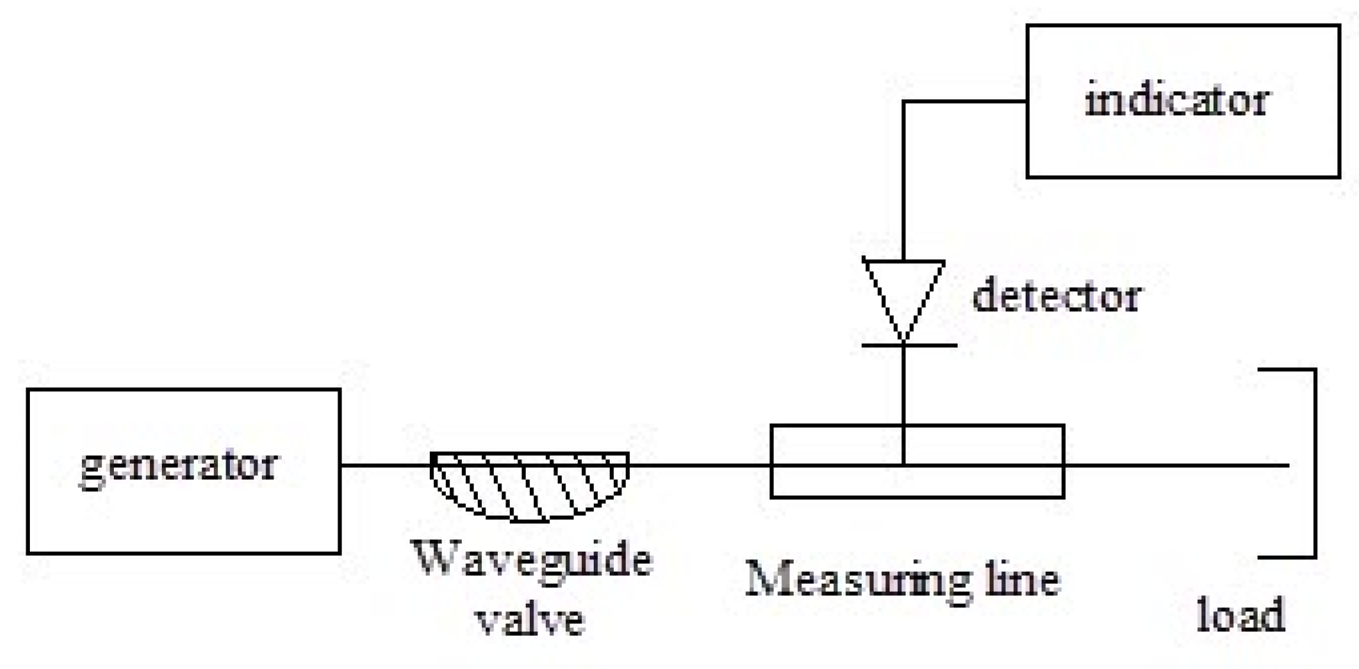
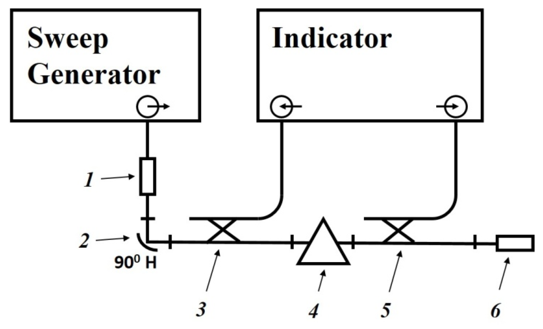
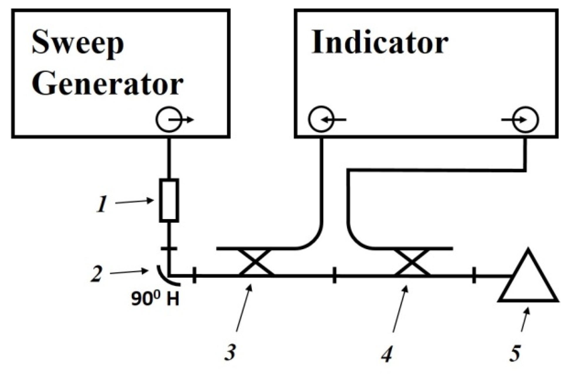
The scheme of the setup used is shown in
Figure 12. The generator signal is modulated by a 1 kHz meander and, after quadratic detection enters the input of a selective microvoltmeter B6–9. The output of it is connected with a digital voltmeter, B7–38. The measuring line has a precise movement mechanism that allows one to determine the position of the probe with an error of 0.01 mm.
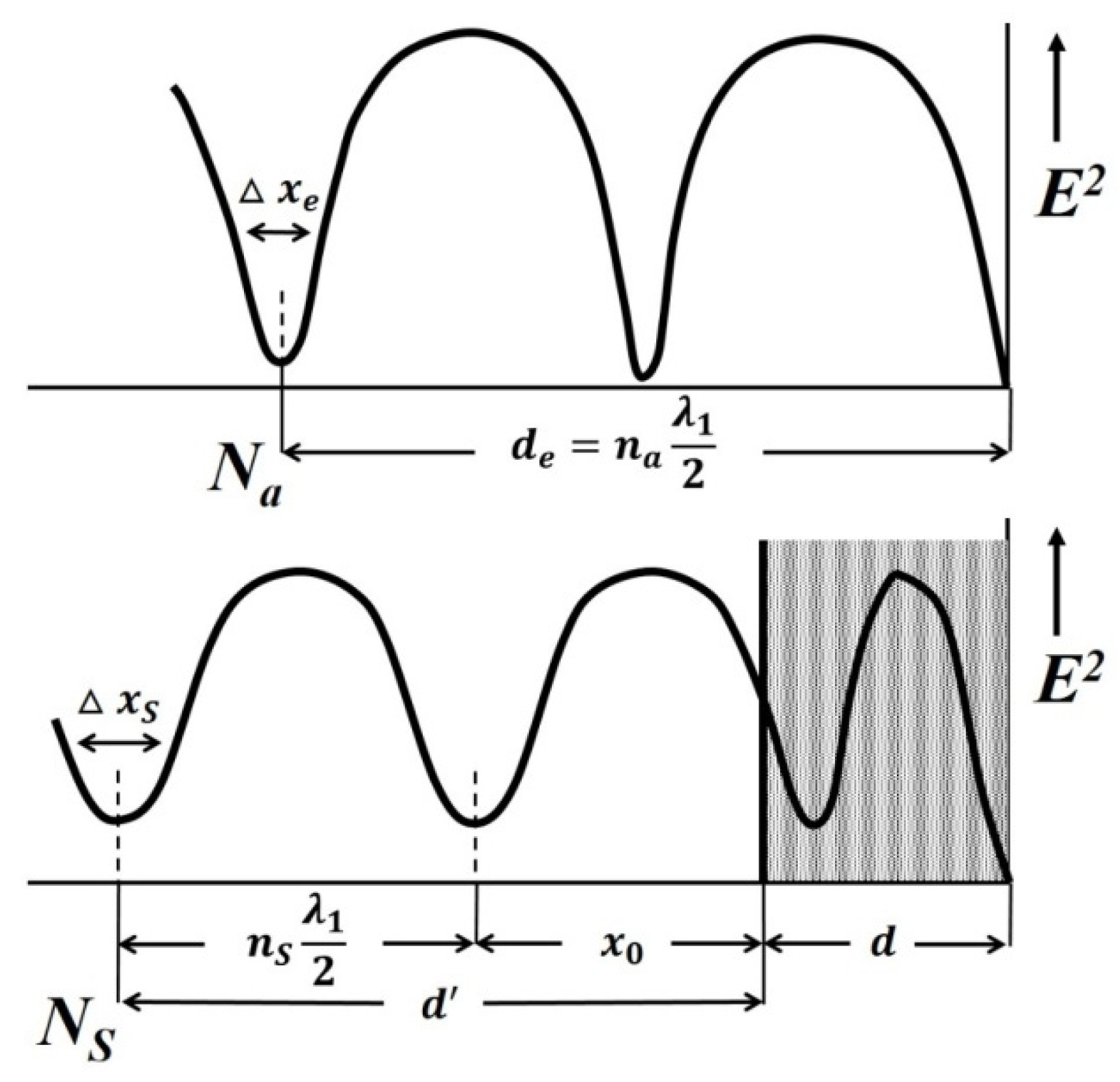
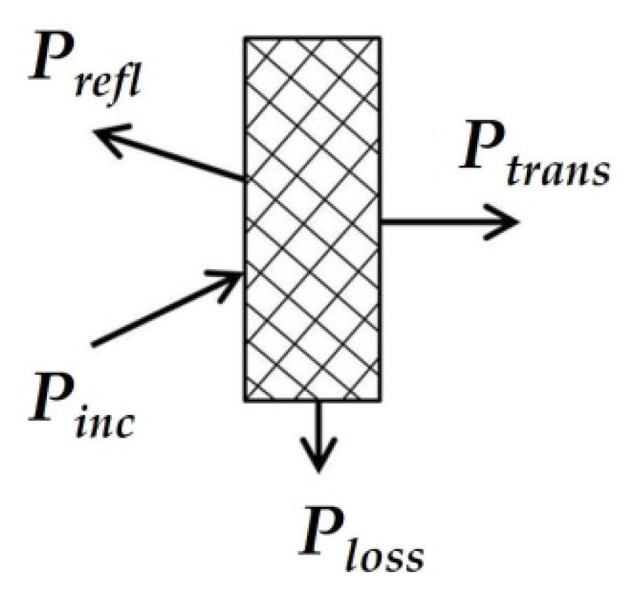
The measurement principle is based on determining the reflection coefficient (or impedance) at the input of a short-circuited line segment filled with the sample under study.
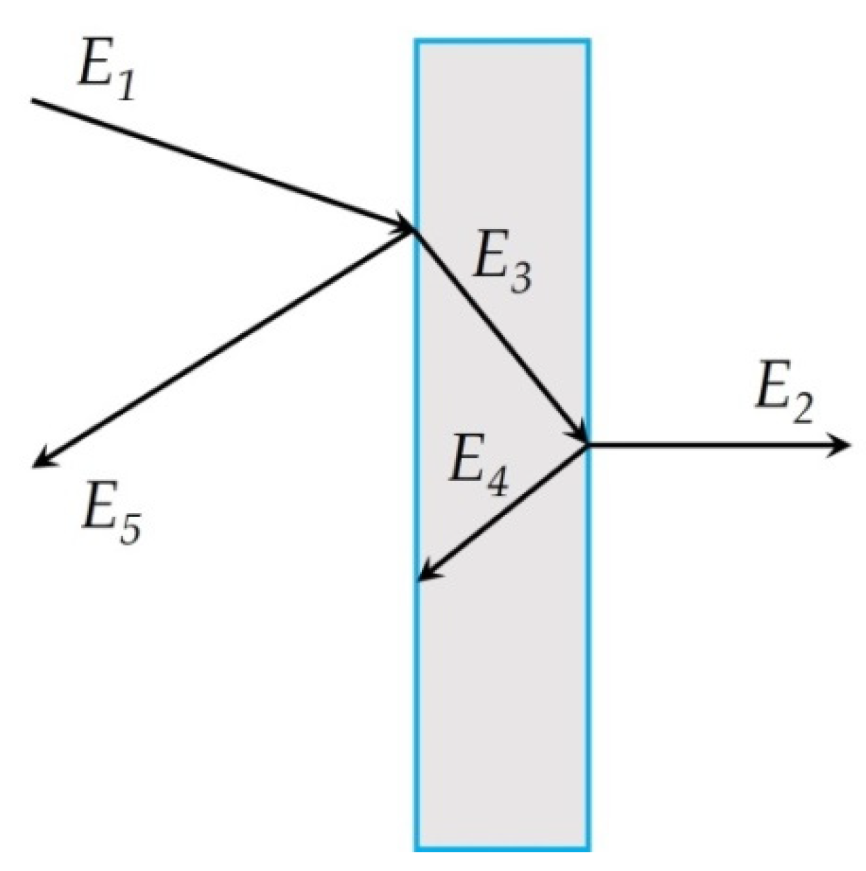
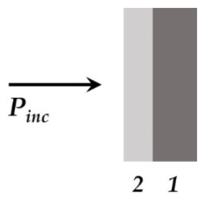
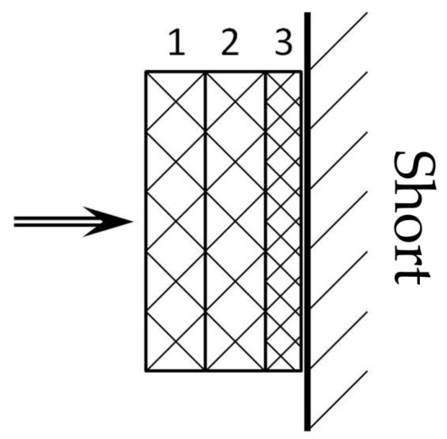
The scheme of inclusion of a sample with thickness
d in the waveguide path and the picture of standing waves are shown in
Figure 13.
An electromagnetic wave falls on the interface with the sample 2 from medium 1 (empty waveguide). The standing wave in medium 1 is the result of the interference of the incident wave and the waves obtained as a result of reflection from the interface (x = 0) and the short-circuit wall. The short-circuit wall can be in two positions: x = d (case of short circuit) or x = d + Δ (case of idling).
The use of a measuring line allows measurements to be made in two positions: short circuit and idle (open line). The equivalent of an open line is a quarter-wave section formed by a movable short-circuited load located behind the sample.
The total resistance in the cross section
x = 0 from the medium 1 can be defined for each position aforementioned by measuring the wavelength in an unfilled waveguide
λ1, the voltage standing wave coefficient (VSWC)
KswU =
Emax/
Emin, and the distance from the boundary of the dielectric to the first node of the standing wave in the direction of the generator
x0:
where
is the wave resistance of an unfilled waveguide,
a and
b are the dimensions of the wide and narrow walls of the waveguide, respectively,
i is imaginary unit.
The total resistance in cross-section x = 0 from the medium 2 are equal to:
Z(0) = Z2 × tanh(γ2d), where Z2 and γ2 are the wave resistance and propagation constant of the waveguide filled with the material under study, respectively, in the case of a short circuit (Δ = 0);
Z(0) = Z2 × cth(γ2d) in the case of idling (Δ = λ1/4).
As a result, complex equations are obtained for determination of the parameters of the waveguide filled with the material under study,
Z2 and
γ2:
Hence, the measured values of the VSWC and x0 for cases of short circuit and idling will be different.
The samples
Fe-01 with 5 wt. % of
Fe(CO)5,
Fe-02 with 10 wt. % of
Fe(CO)5, and
Fe-03 with 20 wt. % of
Fe(HCOO)3 were examined [
129].
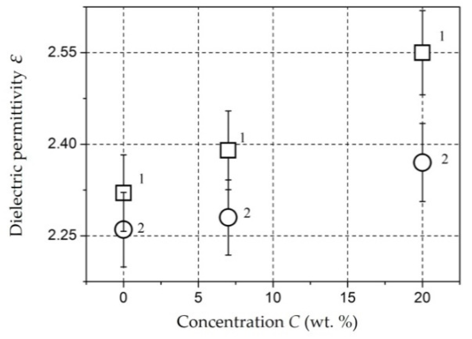
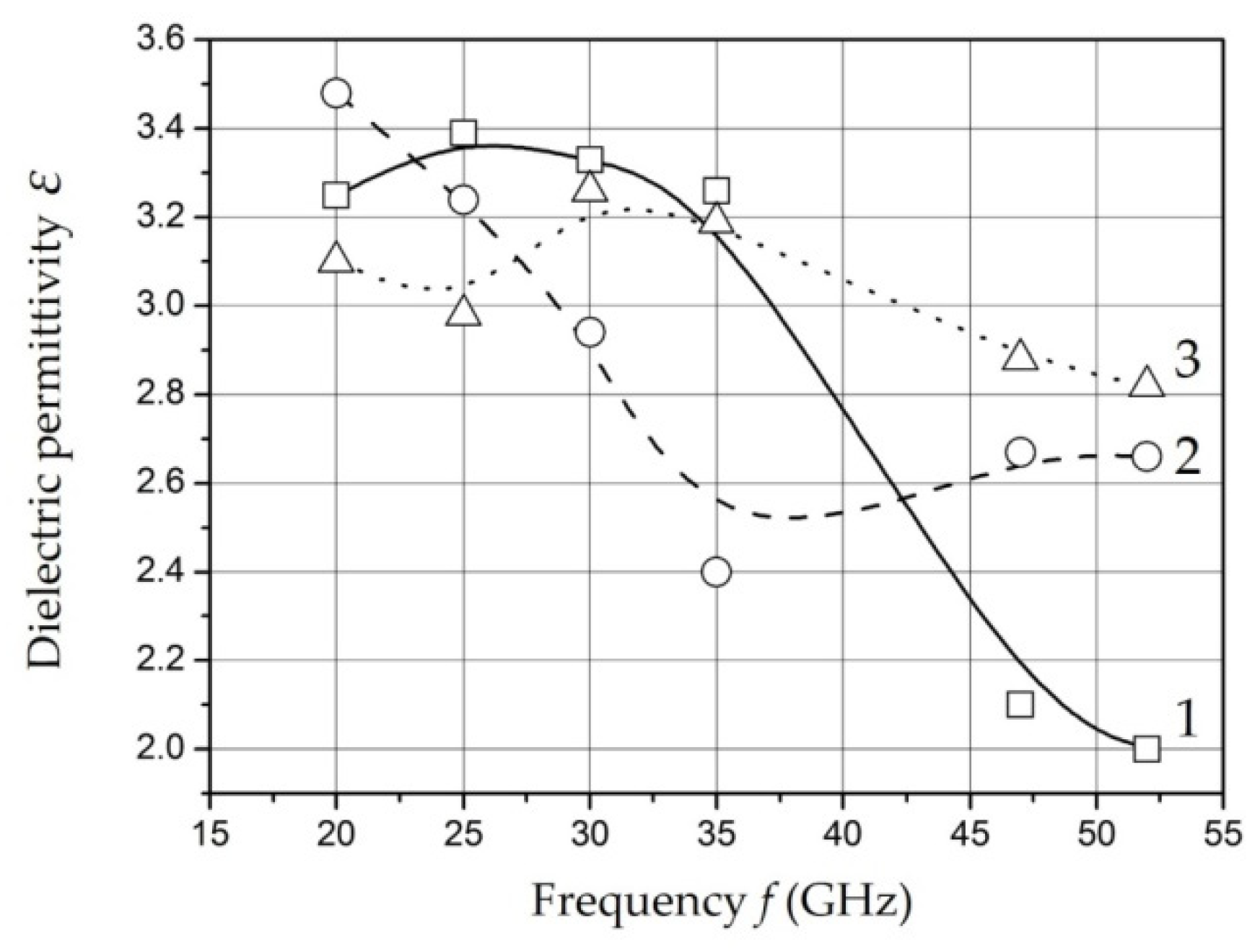
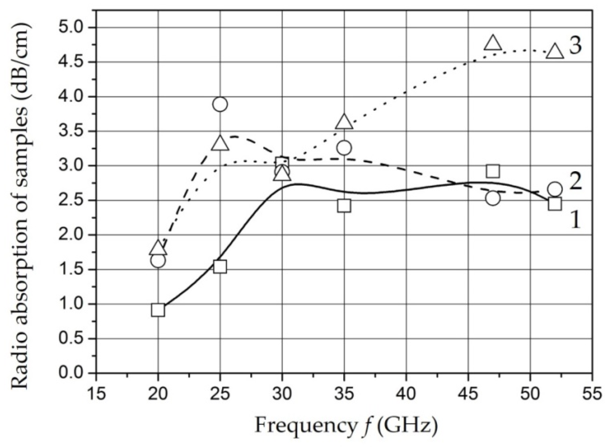
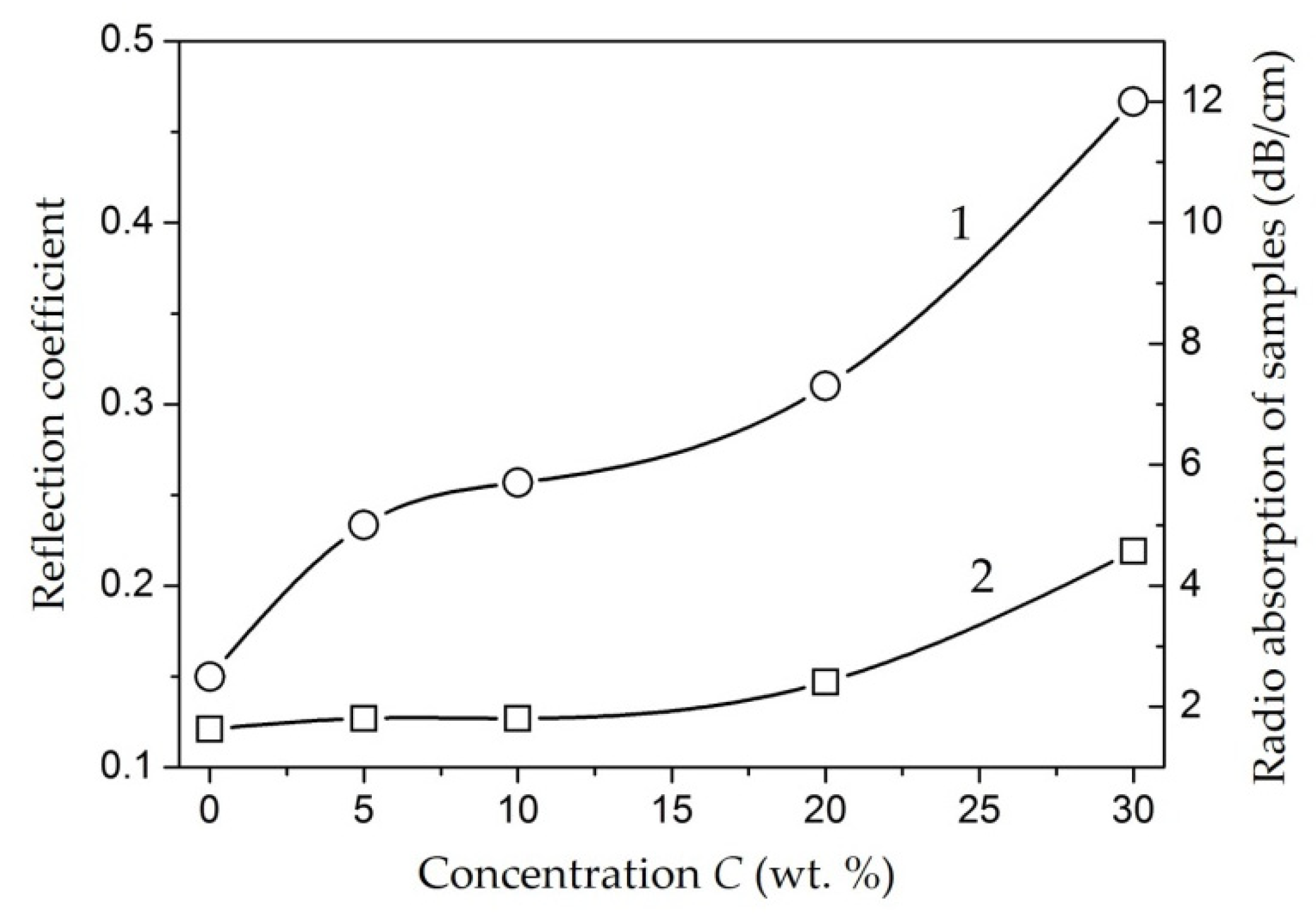
The results of measurements of the dielectric permittivity and water absorption of the samples with different mass filling in the microwave range are shown in
Figure 14 and
Figure 15 [
129].
The ratio of amplitude and time characteristics of relaxation processes can be estimated in according with measurements of the dielectric permittivity and radio absorption of samples in the microwave range. The decrease in dielectric permittivity with a relatively constant level of losses in the operating frequency range for the samples Fe-01 and Fe-02 can be explained by a decrease in the intensity of relaxation processes while maintaining relaxation time. An increase in the content of nanoparticles to 20 wt. % (sample Fe-03) is accompanied by a decrease in relaxation time at a relatively constant intensity.
It should be noted that there is a tendency to decrease the time and increase the intensity of the relaxation process of dipoles with an increase in the content of nanoparticles in the polymer. The obtained dependencies can be associated with the polarization of metal-containing nanoparticles as well as for low frequencies. It is known that its polarizability increases with size of nanoparticles increase [
161]. The results of microwave measurements are characterized in the studied samples as materials having uniform absorption and dielectric permittivity parameters in a wide band of the studied frequency range.
4.4. Investigation of the Properties of Composite Materials by the Resonance Method
The study of the properties of materials using coaxial resonators with an end gap is based on determination of the shift of the resonant frequency and the change in the quality factor of the resonator in the presence of a sample under study [
162,
163]. The method of placing the sample in the resonator depends on what characteristics of the material (permittivity, tangent of the dielectric loss angle, surface impedance, etc.) are going to be measured. The dielectric constant ε and the tangent of the dielectric loss angle tanδ of polymeric composite materials were studied [
104,
146,
151,
164,
165,
166,
167,
168].
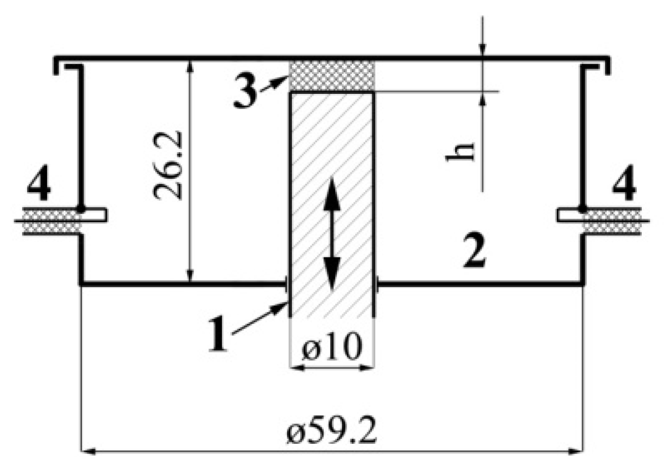
The scheme of an experimental setup based on a measuring coaxial resonator with an end gap is shown in
Figure 16.
The brass resonator is consisted of a movable central rod 1 with a closed cylindrical working volume 2 placed on the axis of 1. The rod is moved by a backlash-free micrometric mechanism equipped with a vernier position indicator. All surfaces inside the working volume are polished and have a silver coating. The capacitive gap 3 is designed for tuning into resonance and for placing samples under study inside it. Its height h can be changed by moving the movable central conductor. The resonator is connected to the signal generator and the spectrum analyzer by means of inductive communication loops 4. The dimensions of the resonator parts used in calculations are presented in
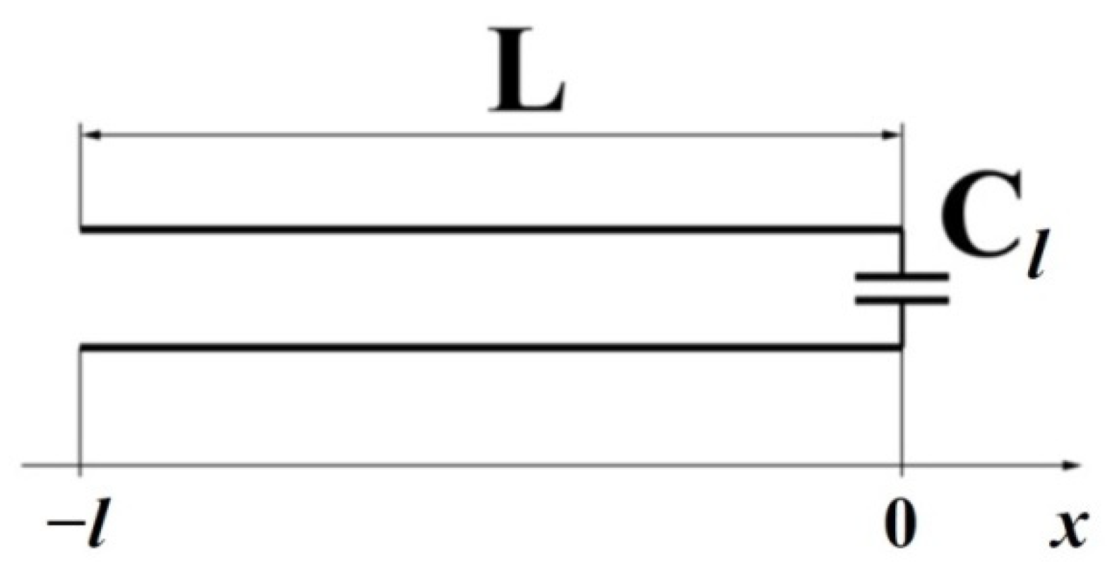
Figure 16. An equivalent circuit of such a resonator is a long line with a capacitive load (
Figure 17).
The resonant frequency of such a circuit can be defined by means the total complex resistance of the long line at its input (in section with the coordinate
x = −
l:
where
Zw and
Zl are wave resistance of the line and resistance of the load, respectively,
γ = α + iβ and is
l = L are the electromagnetic wave propagation constant in the line and length of the line, respectively.
For a line with negligible attenuation (
α = 0), the relation (10) has the form:
The zero input impedance of the line
Zin(–
l) = 0 is the resonance condition. Thus,
Taking into account that, for a capacitive load
Zl = 1/(
i ×
ωr ×
Cl), and also
β =
ωr/
c for an air-filled coaxial line, a nonlinear equation for finding the resonant frequency of a coaxial resonator with an end gap can be obtained:
where
c is the velocity of light in vacuum.
The measurement method has the next algorithm. First, by varying the frequency of the generator, the system is tuned into resonance, and the resonant frequency fr and quality factor Q0 of the resonator are measured without a sample. Then, a sample is placed in the resonator, and the same measurements are carried out again. The resonance frequency fr’ and the quality factor Q’ of the resonator with the sample are obtained.
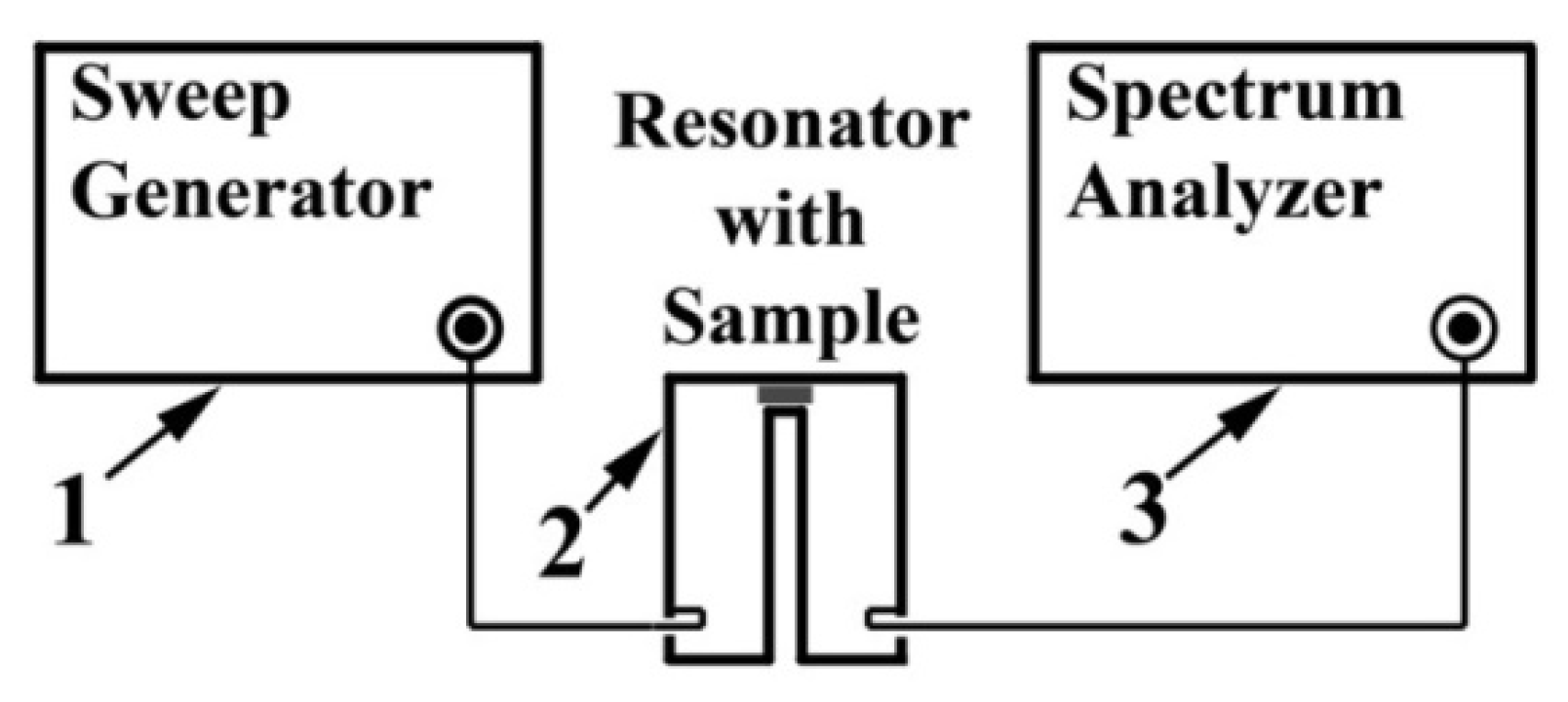
The scheme of the measuring unit is shown in
Figure 18. A signal generator (SME06, Rohde&Schwartz) with operating frequency range of 10 kHz–6 GHz was used as a signal source 1. A spectrum analyzer (FSP7, Rohde&Schwartz) 3, with an upper limit frequency of 7 GHz together with generator 1, makes it possible to observe the resonant curve of the measuring resonator 2 on the screen and automatically perform frequency and amplitude measurements necessary to determine the resonant frequency and quality factor.
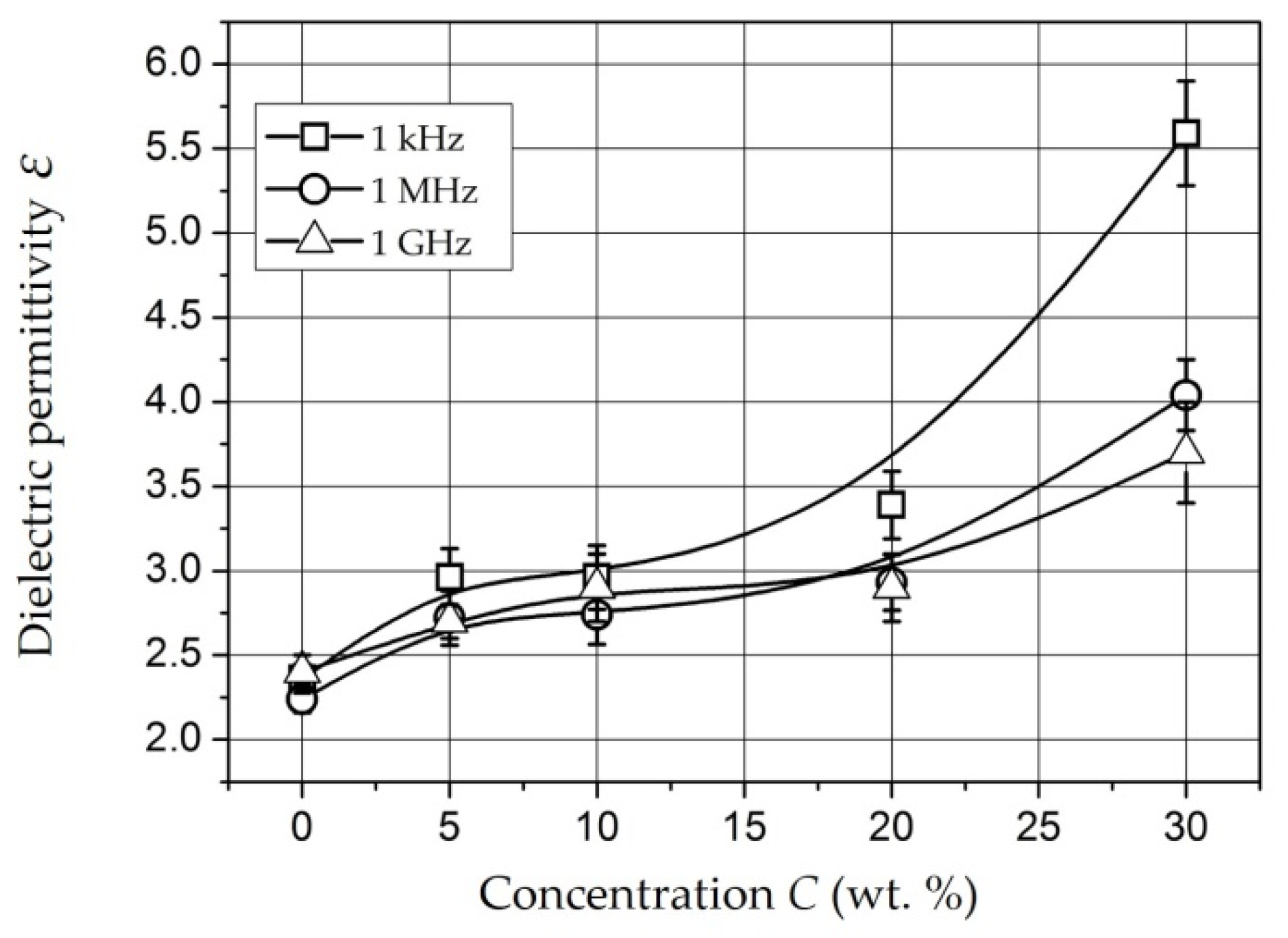
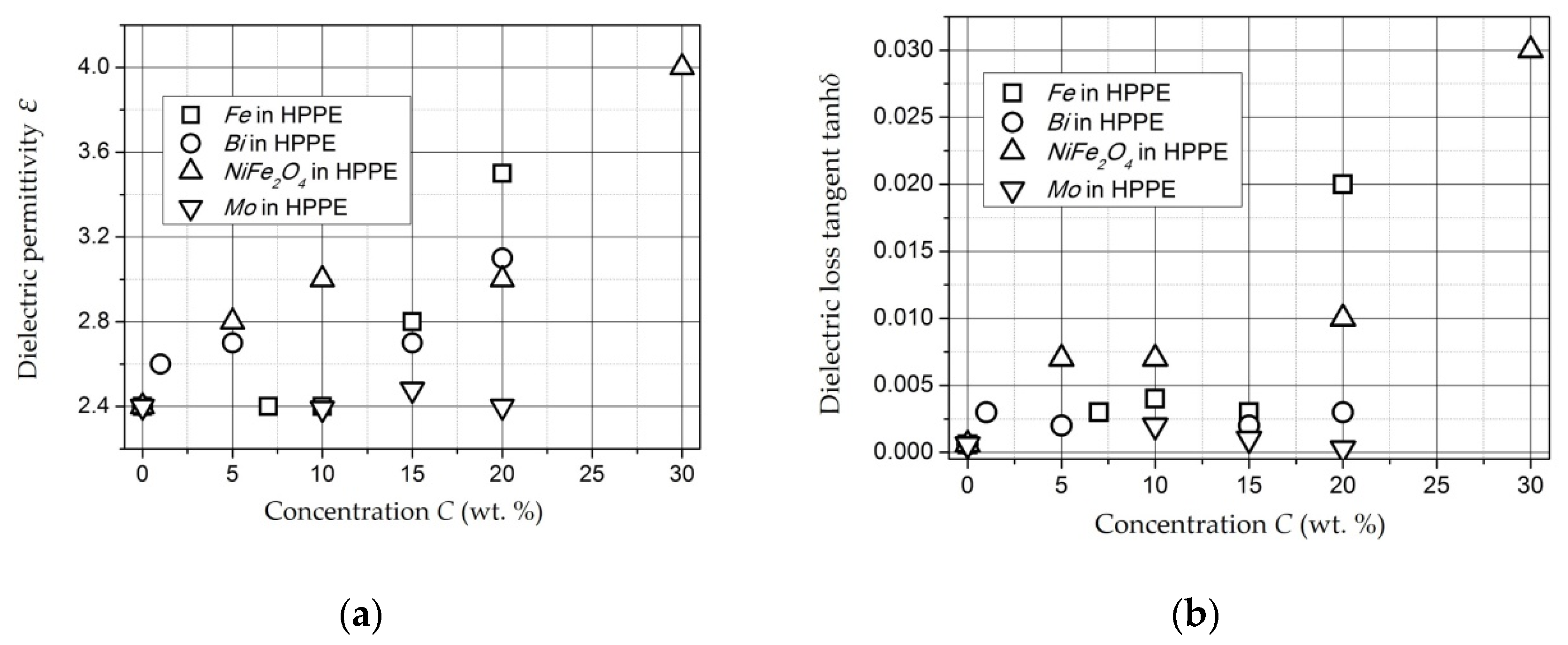
This method was used to study the concentration dependences of composite materials based on
Fe-,
Bi-, and
Mo-containing nanoparticles as well as
NiFe2O4 nanoparticles in a HPPE matrix [
165]. The results of measurements of
ε and tanh(
δ) for samples with
Fe,
Bi,
Mo, and
NiFe2O4 nanoparticles in a HPPE matrix are presented in
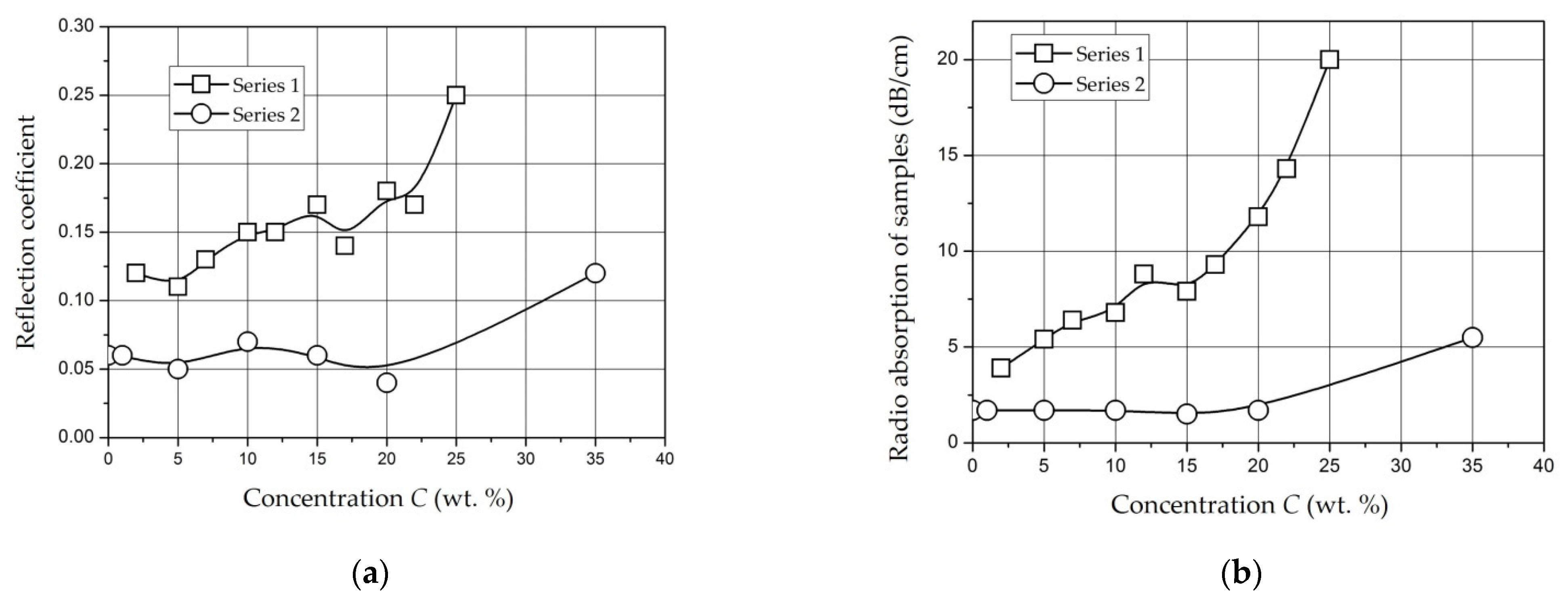
Figure 19. The analysis of concentration dependences allows us to conclude that there are percolation transitions in the concentration range of 15–20 wt. % for samples with
Fe-containing nanoparticles and in the range of 20–30 wt. % for samples with
NiFe2O4 nanoparticles. In the case of
Fe-containing nanoparticles in the ultra-high-frequency range, a shift of the percolation transition to the region of lower concentrations is observed.
The dielectric permittivity of Bi-containing composites also monotonically increases with increasing concentration of the nanoparticles, while tanδ is slightly higher than that of unfilled polyethylene and remains constant up to CBi = 20 wt. %. ε and tanh(δ) of Mo-containing composites in the studied concentration range differ slightly from the values of ε and tanh(δ) of the unfilled matrix.
It should also be noted that the increased values of dielectric permittivity relative to unfilled polyethylene remain in the microwave range. This means that the value of ε of the composite materials based on a nonpolar polyethylene matrix is determined by electronic polarization.
4.5. Magnetic Properties of Composite Materials with Ferromagnetic Nanoparticles
Synthesis and research of nanoparticles with high values of coercive force is an important task on the way to creating new magnetic materials. However, the manufacture of materials from nanoparticles leads to their agglomeration and loss of properties characteristic of individual nanoparticles. Thus, there is a need to create composite materials based on polymers with metal-containing nanoparticles localized into the volume of the matrix. The resulting composite materials are possessed most of the properties inherent in polymers, while the magnetic properties of nanoparticles are preserved [
169,
170,
171]. Polymer composites with magnetic nanoparticles are of particular interest for the development of radio-absorbing materials and coatings. It could be possible since on their basis, it is possible to implement bicomplex electrodynamic media with the complex permittivity (
ε) and permeability (
µ) differing from the unit. Combining ferromagnetic inclusions with inclusions of other types, it is possible to create the desired set of effective broadband radio-absorbing coatings [
172,
173,
174,
175,
176,
177,
178,
179,
180,
181,
182].
Let us consider the magnetic characteristics of the obtained composite materials on the example of
NiFe2O4 and
Fe- and
Co-containing nanoparticles stabilized in the volume of a high-pressure polyethylene matrix [
151,
173,
181,
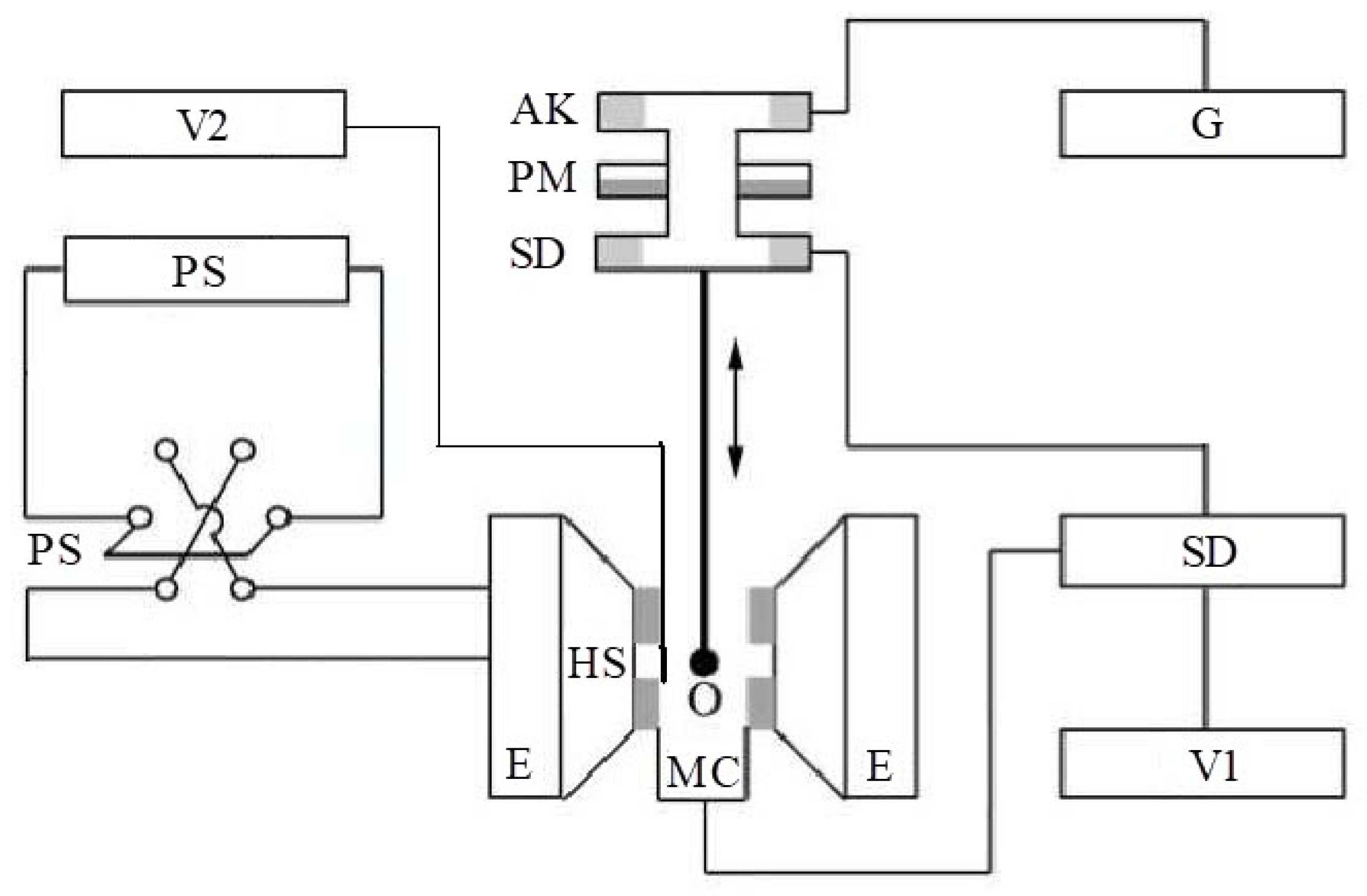
182]. Studies of composite materials containing these ferromagnetic nanoparticles were carried out by the vibration magnetometer method. This technique is based on an induction method for measuring magnetic properties. A scheme of a vibration magnetometer is presented in
Figure 20. A sample O mounted on a rod is set in oscillatory motion in a system of four measuring coils. In this case, the oscillation axis is parallel to the plane of the coils, and the magnetic moment of the sample, induced by an external magnetic field, is oriented perpendicular to the plane of the coils. The coils are located at the poles of the electromagnet (E) sourcing magnetic field. The electromagnetic field (EMF) in the coils is determined by the flux coupling with the sample and depends not only on the magnetic moment of the sample but also on the geometry of the coils and the size and shape of the sample. Therefore, direct measurement of the absolute values of the magnetic moment (magnetization) is difficult. As a rule, a comparison method is used with a reference sample, which has a size and shape close to the sample under study and known magnetic characteristics.
By means of the induction measurement method, only the magnetic moments of the samples can be directly compared. In order to move on to specific characteristics (magnetization
M or specific magnetization
σ), it is necessary to know the volumes or masses of the samples. Magnetization is the magnetic moment of a unit of volume. It has the dimension (G) or (A/m). Specific magnetization is the magnetic moment of a unit of mass. It has the dimension (G × cm
3/g) or (emu/g) or (A × m
2/kg). These characteristics are interconnected through the material density
ρ:
It is easier to determine the mass of samples from experiment. Therefore, in comparative measurements, specific magnetization is more often used.
In works [
151,
173,
181], the studies were carried out by means of a vibrating magnetometer (PAR-155, EG&G) with an absolute sensitivity of 10
−5 emu. The noise level at the integration time of 1 s and 3 s were 5 × 10
−5 emu and 2 × 10
−5 emu, respectively. The diameter of the electromagnet poles and the distance between poles were 60 mm and 50 mm, respectively. The value of the field in the gap can be 1.2 T at a current of 22 A. As part of the setup, a power supply unit was used to provide the maximum current values at the level of 8 A; therefore, the maximum field values were limited to 0.5 T. It was usually sufficient for the studied compositions. Magnetic field was measured by means of a Hall sensor. Power to a Hall sensor was supplied from a precision 100 mA current source. The potential was measured by a voltmeter having a sensitivity of 0.1 µV. The final field resolution was 0.01 G. The relative error did not exceed 0.5%. A helium cryostat with the temperature range 4.2–300 K was used for measurements at low temperatures. The temperature was measured and stabilized using a temperature controller. The accuracy of temperature stabilization was 0.1 K at temperatures below 100 K and not worse than 0.2 K for temperatures of 100–300 K.
The sample size could not exceed 3 mm due to cryostat restrictions. The measuring error in the magnetic moment associated with the size and shape of the sample did not exceed 1% for such sample sizes. The magnetometer was calibrated according to a nickel sample at room temperature.
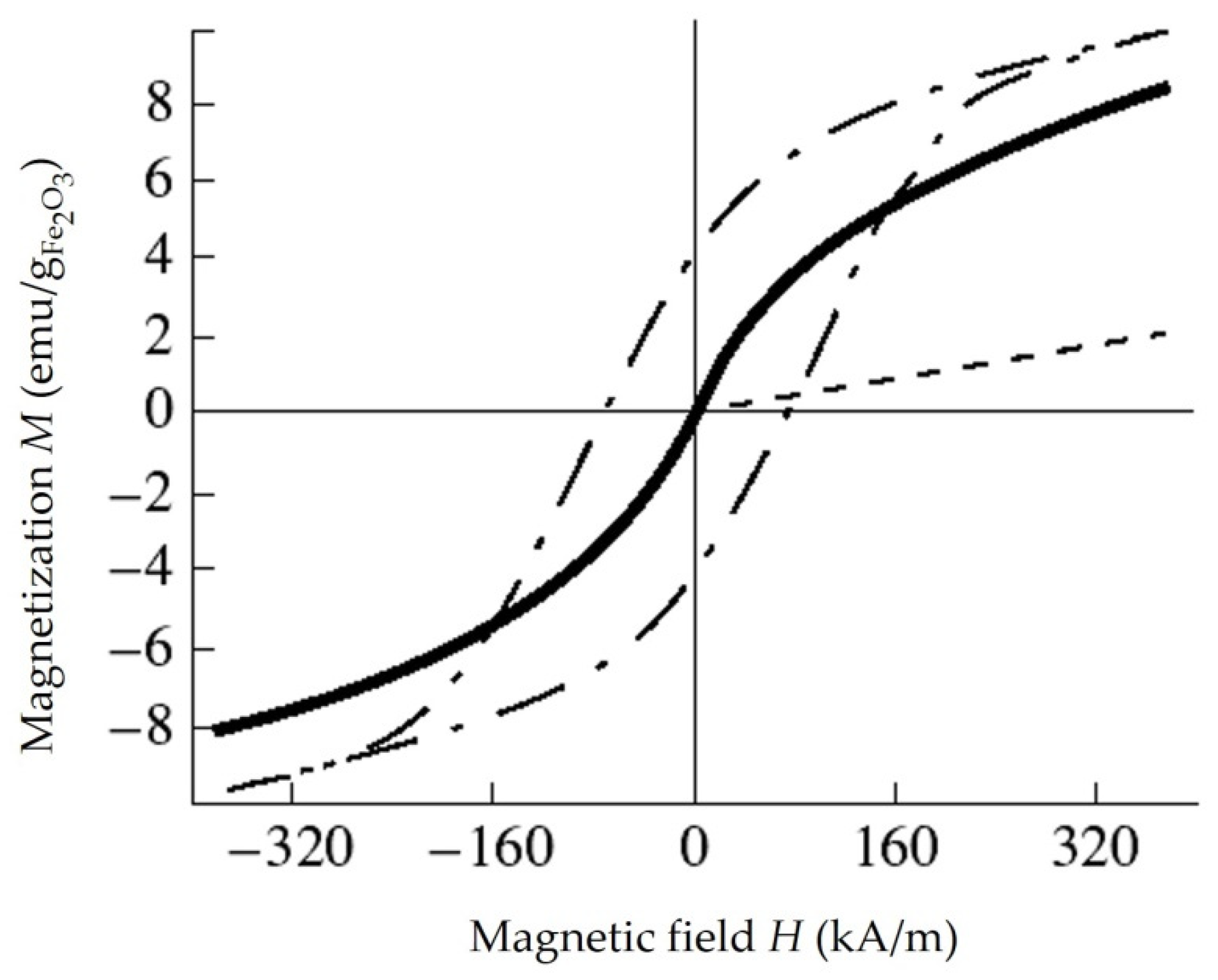
Iron-Containing Composites [
173,
181]. The experimental dependence of the magnetization
M on the magnetic field
H for a sample containing 5 mass. %
γ-Fe2O3 in a polyethylene matrix at room temperature (293 K) is presented in
Figure 21 [
181].
It can be seen that the experimental dependence of magnetization M(H) is nonlinear and does not detect saturation in the 4.7 kOe field, nor does any hysteresis occur on it. The shape of the curve M(H) indicates that the system of magnetic particles γ-Fe2O3 in the sample at room temperature is in a superparamagnetic state. Similar results were obtained at other concentrations of γ-Fe2O3 in the HPPE matrix.
In addition to the above measurements, the effect of temperature on the magnetic properties of the obtained composite materials consisting of a matrix of high-pressure polyethylene and iron-containing nanoparticles synthesized by decomposition of iron pentacarbonyl was studied. The studied samples were heated for 10 min in air at temperatures of 195 °C, 215 °C, 240 °C, 260 °C, and 290 °C. At each temperature, six samples obtained by the same method were heated, and all of them were examined in order to exclude experimental error. After warming up, three samples from each series were magnetized and cooled in a magnetic field with the strength of 7 kOe, which we will call the “texturing” field. The remaining three samples were examined without processing by a “texturing” field.
For samples cooled in a magnetic field, magnetization loops were measured both along and across the direction of the “texturing” magnetic field. As a result of the studies, no difference was found in the magnetization curves of “textured” and non-”textured” samples in the magnetic field. It was typical for all series of samples subjected to temperature treatment.
Such behavior of samples containing a magnetic component in relation to the directed magnetic field applied to them can be explained by two reasons. The first is the formation of strong chemical bonds between the matrix and metal nanoparticles localized in it, and the second is the small contribution of the magnetic anisotropy of the shape to the overall magnetic anisotropy of the particles.
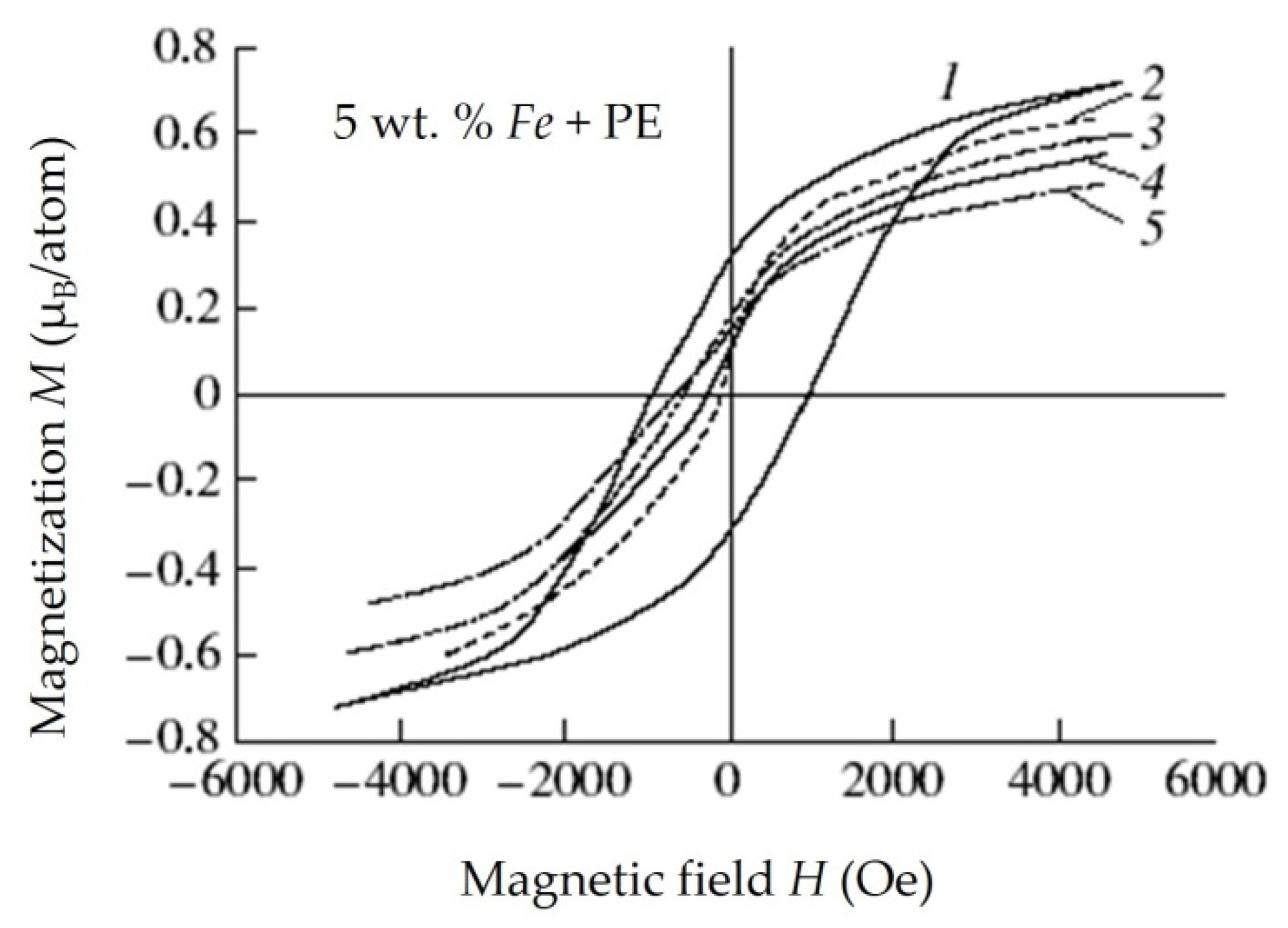
The hysteresis loop of the initial sample and the demagnetization curves of the entire series of heat-treated samples are shown in
Figure 22 [
173]. The corresponding values of the residual magnetization of samples and samples placed in a magnetic field with the strength of 4.5 kOe as well as their coercive force at room temperature and at temperature of 100 °C are presented in
Table 7.
During the research, it was noted that even at a temperature of 240–260 °C, when the polyethylene melts, a coercive force is observed in the sample. However, compared to the initial sample, it is much smaller. This can be explained by the formation of
γ-Fe2O3 due to the oxidation of the metal phase in nanoparticles. Iron (III) oxide has a lower magnetocrystalline anisotropy compared to metallic iron, which is the base component in the initial composite material [
181].
A specific behavior of residual magnetization was observed for all the studied samples that underwent heat treatment. However, one trend can be noted that, with an increase in the calcination temperature of the samples, there was a decrease in the magnitude of their residual magnetization, and a decrease in the magnitude of the coercive force of the materials studied was also noted. However, when the samples were magnetized in a magnetic field with strength of 4.5 kOe, a decrease in the magnitude of magnetization was observed at first and then its increase. This feature is most likely related to the redox processes that occurs when the composite material is heated and the partial destruction of the matrix material on the basis of which the composite is obtained.
According to the data of Mossbauer spectroscopy, the following transformations occur with nanoparticles in synthesized materials. Initially, the oxidation of nanoparticles to iron (III) oxide occurs, a further increase in temperature leads to the polymer matrix starting to collapse, resulting in the reduction of iron (III) oxide to
Fe3O4. Such a heat treatment process at temperatures close to the destruction temperature of the matrix can be successfully used to increase the residual magnetization in samples [
181].
The study of the temperature behavior of magnetization was carried out for a sample that was first calcined at a temperature of 210 °C for 10 min and then underwent additionally 60 min calcination. According to the data obtained, it was noted that additional calcination leads to a decrease in the coercive force by about 5%. It may be associated with the oxidation of nanoparticles.
The effect of low temperatures on the magnetic properties of synthesized iron-containing composites was also investigated. The nanomaterials containing 5 wt. % of iron-containing nanoparticles in the volume of the polyethylene matrix (having a coercive force of 950 Oe) were investigated. The effect was carried out in a cyclic mode. Initially, the sample was cooled to −70 °C, kept at this temperature for 2 h, and then quickly heated to a temperature of +60 °C for 2 min and kept at the same temperature for 30 min and then quickly frozen again. Five such cycles with each sample were carried out. Along with this, a series of samples were kept only at −70 °C for 9 h, and three samples were kept for 21 h. Such temperature effects did not have a significant effect on the coercive force of the studied nanomaterials, and its changes amounted to 30–50 Oe.
Cobalt-Containing Nanocomposites. Among the works devoted to materials with nanoparticles of magnetic metals, after traditional iron, cobalt occupies the second place [
169,
179,
182]. Cobalt in the form of samples of ordinary (macro) sizes is a ferromagnetic metal with a Curie temperature of
TC,b = 1390 K. This is the highest value for existing magnetic materials [
183]. It characterized by a saturation magnetization of
MS,b = 1.79 T at room temperature and coercive force
Hc,b = 10 Oe [
184,
185]. The hexagonal
α-phase of cobalt is stable at temperatures below 420 °C. The cubic
β-phase of cobalt is stable above 420 °C. The crystal structures of α- and β-phases are close, and their saturation magnetizations also almost coincide. The magnetic anisotropy for the cubic modification is less than for the hexagonal one. It is of
Kv = 2.5 × 10
5 J/m
3, 7.5 × 10
4 J/m
3, or 2.5 × 10
4 J/m
3 according to data from [
186,
187,
188], [
189], or [
190,
191], respectively. For the hexagonal phase,
Kv = 4.5 × 10
5 J/m
3 [
192]. In most of the synthesis methods used today, cobalt nanoparticles are obtained with cubic structure, but in some cases, it is possible to obtain
Co nanoparticles of a hexagonal structure [
193]. It should be noted that in the case of the synthesis of cobalt nanoparticles by methods of “wet” chemistry under certain conditions, nanoparticles of a primitive cubic structure or ε-cobalt are formed [
194]. The new
ε-phase of cobalt was first observed namely in nanoparticles.
The hysteresis loops of a sample containing 5 wt. %
Co in a polyethylene matrix were measured at 4.2K, 77K, and 295 K [
138]. It has been found that unlike the samples containing
γ-Fe2O3 nanoparticles and considered above the system of nanoscale, magnetic
Co particles in the sample are in a state of blocking both at low temperatures and at room temperature. Consequently, the blocking temperature for this sample is above room temperature. Upon cooling, the coercive force increases, reaching a value of 680 Oe at 4.2 K. Attention is drawn to the large magnitude of magnetization per atom. It was equal to 1.05 µ
B/atom and 1.93 µ
B/atom in the field of 4.5 kOe at 295 K and 4 kOe at 4.2 K, respectively, while it is known that the saturation magnetization of metallic Co at 4.2 K is equal to 1.7 µ
B/atom. Thus, in the studied sample with
Co nanoparticles in a polyethylene matrix the magnetic moment of cobalt is overestimated in comparison with the value for the bulk material. The possibility of an increase in the magnetic moment per atom in nanoparticles of 3d transition metals
Fe,
Co, and
Ni was predicted earlier using theoretical calculations [
195]. This an increase was observed experimentally in particles with a diameter of 10–25 Å in a polymer matrix, in 18–44 Å
Co particles in micelles, and in experiments with beams of superparamagnetic nanoparticles of
Fe,
Co, and
Ni [
184,
195]. In this case, the reason of the magnetic moment increase is probably laid in the fact that the core and shell of the particle have a different structure.
Along with the above, the effect of temperature exposure on the samples with
Co nanoparticles was studied. The synthesized composite nanomaterials containing
Co nanoparticles were exposed to temperature 280°C in air for 2 h. The results obtained on the change in magnetic properties after heating are presented in
Table 8 [
182].
As it can be seen from
Table 8 the calcination does not lead to a change in the coercive force of the samples under study. This may be due to the oxidation resistance of cobalt-containing samples during heat treatment. At the same time, the magnetization value of the sample after calcination increased almost two times compared with the original sample. Most likely, this increase in magnetization may be due to the processes of crystal transformations in the structure of cobalt nanoparticles. It was also noted that cobalt-containing samples were more resistant to the effects of oxygen in the air when heated compared to iron-containing samples. Recall that when the latter were heated in air, it led to a decrease in their coercive force (
Hc) and magnetization (
MR) (
Table 8).
The investigations of cobalt nanoparticles allow us to better understand the specifics of the magnetic behavior of nanoscale objects. To date, it is clear that a simple model of single-domain, non-interacting nanoparticles in most cases turns out to be too rough although it describes many phenomena qualitatively correctly. Real nanoparticles are different in size, shape, internal structure, and therefore in properties. It is necessary to take into account the existence of a “core” and a “shell” in a particle with different magnetic characteristics as well as their interaction with each other. The magnetic anisotropy of cobalt nanoparticles is mainly determined by their surface. Thus, it depends on the properties of the matrix surrounding them.
Therefore, it is necessary to conclude that, now, there is no complete theory that would allow describing the magnetic properties of a set of nanoparticles. We can only talk about individual models that more or less successfully describe a limited number of experimental works. One of the reasons for this situation is the strong dependence of the properties of nanoparticles on the method of production and on the conditions of synthesis within the framework of one method, which makes the concept of “cobalt nanoparticle” insufficiently clearly defined.
Nanocomposites Containing Nickel Ferrite Nanoparticles. The magnetization curves of the disk samples with a diameter of 5 mm and a thickness of 1.5 mm were carried out by means of an automated vibromagnetometer [
151]. The demagnetization curves of the samples and the dependence of
σS (emu/g) on concentration
C are shown in
Figure 23.
It was found that the materials under study can be classified as soft magnets. The saturation magnetization σS in them is achieved in fields of 2 kOe and increases with increase concentration C. Point C = 100 wt. % is corresponded to a tabular value. Thus, for a composite based on NiFe2O4 nanoparticles stabilized in a HPPE matrix, the value of σS = 38 is comparable to σS = 50 for massive NiFe2O4.
4.6. Magnetic Properties of Composite Materials with Para- and Diamagnetic Nanoparticles
The magnetic characteristics of nanocomposites based on high-pressure polyethylene (HPPE) and magnetic nanoparticles (for example, iron- and cobalt-containing) have been studied in sufficient detail as shown above. At the same time, a wide range of non-magnetic composite nanomaterials has been obtained. These are materials based on
Mo-,
Bi-,
Pb-, and
Re-containing nanoparticles as well as materials based on
CdS,
Cu,
Hg, and
CeO2 nanoparticles stabilized in a HPPE matrix [
121,
124,
146,
150,
155,
156,
157,
158,
159,
196,
197]. In order to comprehensively study the properties of such composite nanomaterials, it is of interest to study their magnetic properties.
One of the most common methods of studying the magnetic characteristics of weakly magnetic substances is the Faraday method. The method is based on measuring the mechanical force acting on a sample in an inhomogeneous magnetic field. In this case, the sample under study is placed directly in the region of the maximum field gradient, and the sample size is chosen so that the field gradient does not change significantly in its volume [
198].
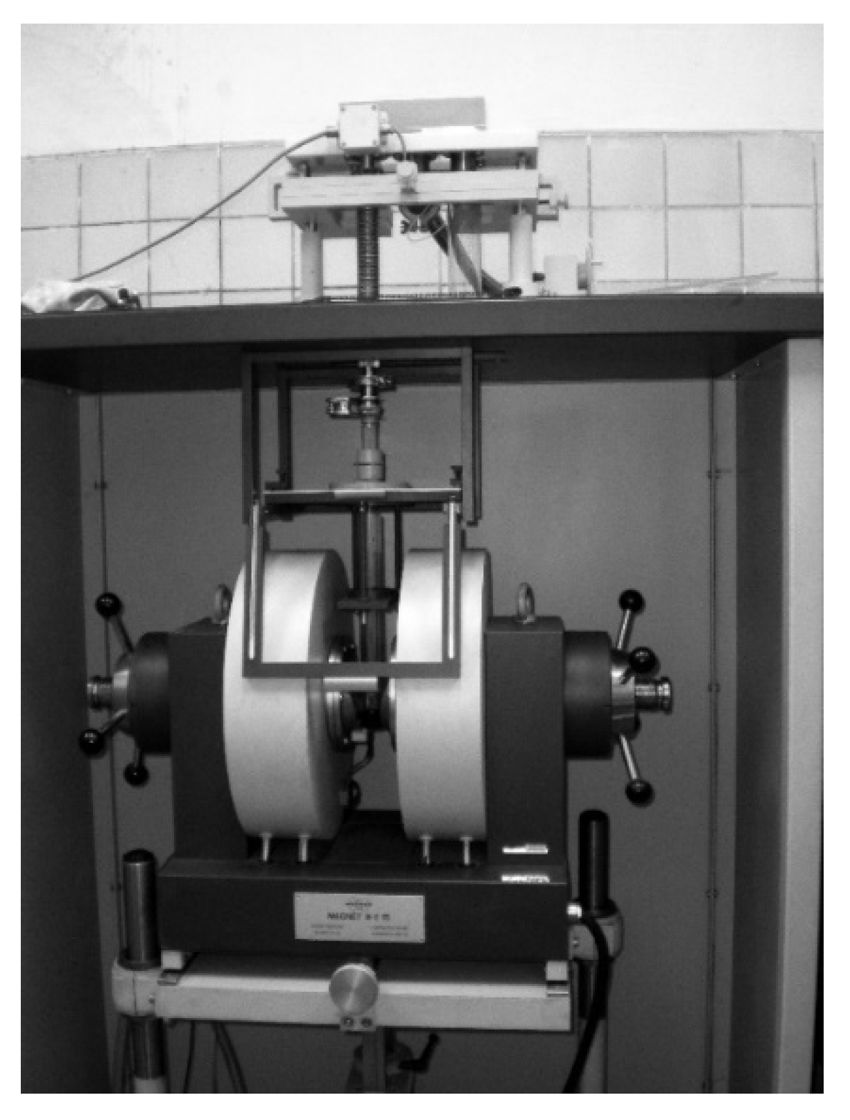
An experimental setup consisting of a Bruker magnetic field control system and Sartorius electronic microweights was used for measurements of the magnetic characteristics of weakly magnetic nanocomposites. The photo of this setup is presented in
Figure 24. The main element of the magnetic field control system is a water-cooled electromagnet. To create an inhomogeneous magnetic field, the electromagnet has pole tips of a special shape that ensure the constancy (BdB/dz) of the magnitude in a sufficient working interval for measurements
Δz. The maximum value of the magnetic field strength in the working area of the electromagnet gap is 6.5 kG.
Lever microbalance with electronic balancing and indication are used to measure the force acting on a sample placed in an inhomogeneous magnetic field. A microbalance has two measuring ranges with a sensitivity of 1 and 10 micrograms.
The disk samples with a diameter of 5 mm and a thickness of 1–2 mm were located at the bottom of the cup, so the condition of constancy of the magnetic field intensity gradient in the sample volume was met.
The force
Fz acting on the sample in an inhomogeneous magnetic field with a gradient dB/dz (in the CGS system):
where
M =
V ×
JM is a magnetic moment in G × cm
3,
V is a volume in cm
3, and
MJ is a magnetization of the sample in G; χ is a magnetic susceptibility of the sample;
=
χ/
ρ is a specific magnetic susceptibility of the sample in cm
3/g;
m is a sample weight in g;
Fz is a power in dynas;
Bd
B/d
z is in G
2/cm.
It is necessary to know the force acting only on the sample for calculations. The measurements were made with an empty cup to this purpose, and the desired force was calculated as the difference:
where indexes
S,
T, and
G mean sample, total, and glass tube.
The product BdB/dz can be calculated according to the ratios (15) and (16) based on the results of measurements using a standard material with a known susceptibility. Copper sulfate CuSO4·5H2O was used as a standard material. Its magnetic susceptibility was assumed to be 5.94 × 10⁻⁶ cm3/g. The magnetic field strength in the working area of the electromagnet gap was measured by a teslameter as a function of the vertical coordinate and the field strength set by the electronic controller.
The dependence of the magnetization of samples on the magnetic field strength
Jsp(
B) for weakly magnetic samples of nanocomposites can be obtained from the results of measurements of the force acting on the sample. The magnetic moment of the sample (in G × cm
3) in the field of intensity
B:
Then the specific magnetization of the sample
Msp (emu/g):
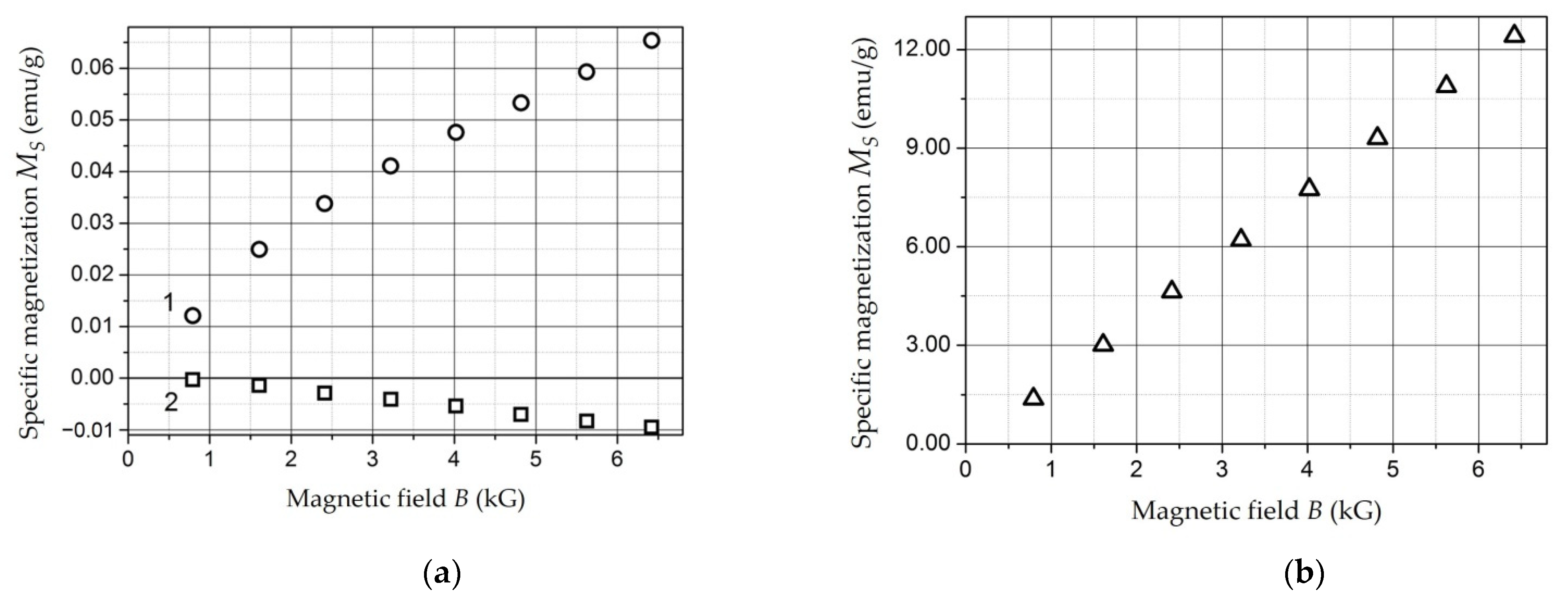
The magnetization curves
Msp(
B) =
MS(
B) of the test samples are plotted based on the results of measurements and using the ratios (15)–(18). These dependencies are presented in
Figure 25. The test samples were based on
Al,
Zn, and a sintered ceramic sample
Ho2Ti2O7.
The specific magnetic susceptibility of the test samples was calculated using parameters
Am and
Cm of the linear regression of the magnetization curve:
The results obtained are presented in
Table 9. It is correlated well with the literature data [
199].
Then, according to the described method, measurements were performed, and magnetization curves were obtained for samples of weakly magnetic composite materials based on Mo, Bi, CeO2, CdS, Pb, Cu, Hg, and Re nanoparticles stabilized in a HPPE matrix.
First of all, it should be noted that the values of the specific magnetization of composite nanomaterials samples according to the research results did not exceed 0.1 emu/g in absolute values. This corresponds to the specific values for weakly magnetic substances including Zn and Al.
The studied samples can be attributed to two groups in accordance with the view of the obtained experimental dependences of magnetization on the magnetic field strength MS(B).
1. The samples based on
Mo,
Bi,
Hg, and
Re nanoparticles as well as a sample from unfilled HPPE that has undergone reaction treatment are characterized by negative magnetization at all values of the magnetic field strength. Its dependence
MS(
B) is satisfactorily described by a decreasing linear regression (19), while the value of the parameter
Am of the linear regression can be assumed to be zero. Thus, such samples are diamagnets. The values of the specific magnetic susceptibility for these samples calculated by parameter
Cm of the linear regression of the magnetization curve are presented in
Table 10.
As can be seen, the magnetic susceptibility of the composites based on Bi-, Hg-, and Re nanoparticles differs slightly from the susceptibility of unfilled HPPE. The embedding of Mo-containing nanoparticles into the matrix is lead to reduce by almost two times. This may be due to the presence of paramagnetic molybdenum oxides of different valence in the composite based on Mo-containing nanoparticles.
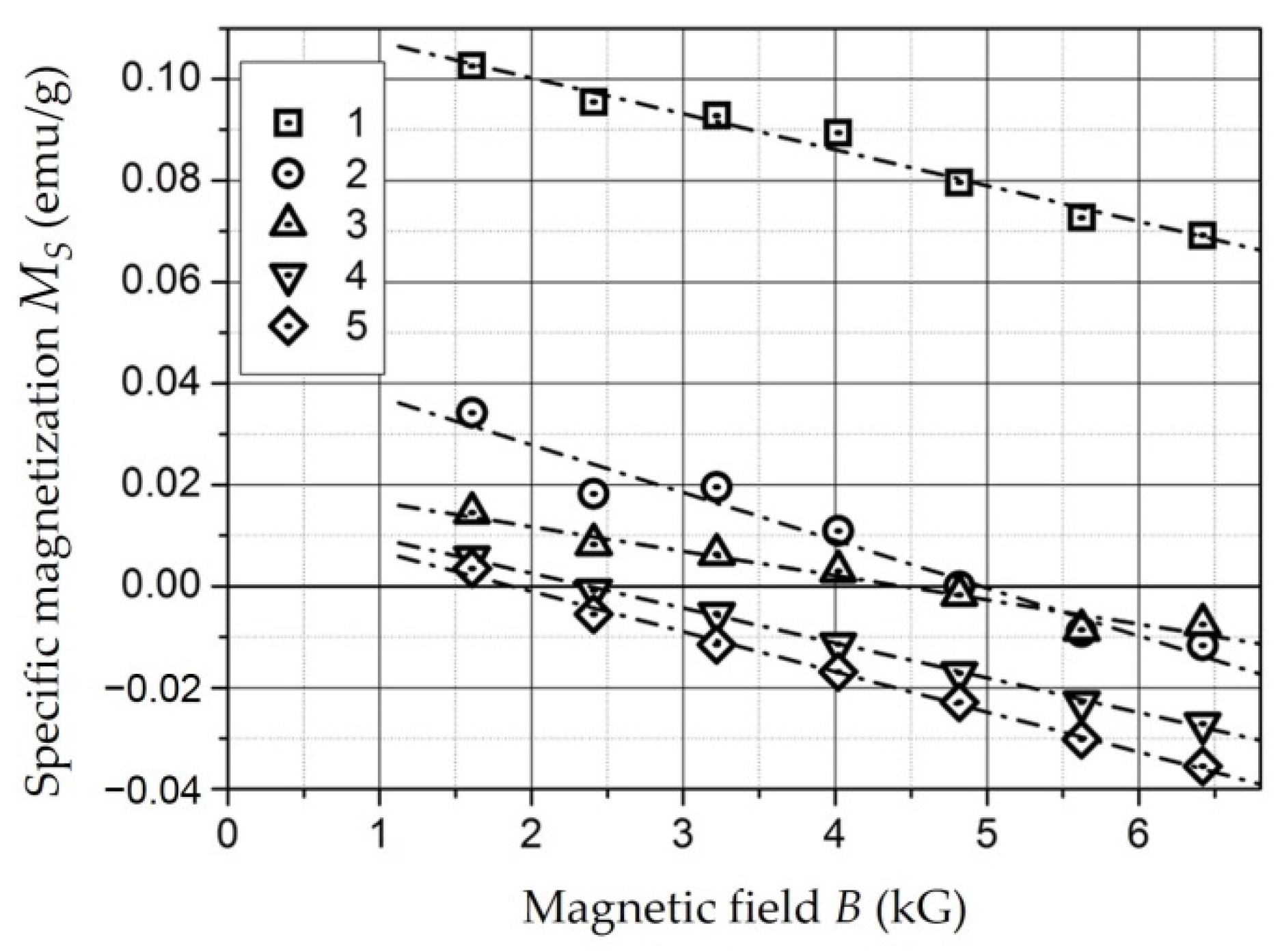
2. The magnetization of the samples based on
Cu-,
Pb-,
CeO2-, and
CdS-containing nanoparticles stabilized in a HPPE matrix is changed from positive to negative at a certain value of the magnetic field strength. In this case, the dependence
MS(
B) at values of
B = 1.5–6.5 kG is satisfactorily described by a decreasing linear regression of the form (19). The magnetization curves
MS(
B) of these samples are shown in
Figure 26. The values of the specific magnetic susceptibility for these samples calculated by parameter
Cm of the linear regression of the magnetization curve are presented in
Table 11 for fields with intensity
B = 1.5–6.5 kG.
The behavior of the samples in the field B > 2 kG is diamagnetic. The vertical displacement of the magnetization curve is equal to the linear regression parameter A, and it makes sense for some “initial magnetization” of MS-0. It is achieved at B < 2 kG and remains constant with a further increase in the magnetic field strength.
The value MS-0 for the studied samples is in the range of 0.014–0.12 emu/g. The source of this “initial magnetization” may be composite components with magnetic properties (para- and antiferromagnetic), the magnetization of which reaches saturation in weak fields. Their presence in low concentrations is due to both the manufacturing technology of nanocomposites based on HPPE containing nanoparticles and the complex phase composition of nanoparticles. For example, in the case of copper, copper (II) oxide CuO has antiferromagnetic ordering as well as copper and oxygen complexes with hydrocarbon molecules.
It should also be noted that the magnetic susceptibility of composites based on Cu-, Pb-, and CdS-containing nanoparticles differs slightly from the susceptibility of unfilled HPPE. The introduction of CeO2 nanoparticles into the matrix leads to a decrease at a relatively small value MS-0; i.e., as in the case of molybdenum, there is a paramagnetic contribution to the magnetization of the composite in fields with a strength of 1.5–6.5 kG. At the same time, there is a dependence of the effect on the concentration of the filler.
Thus, samples of nanocomposites based on Cu, Pb, CeO2, and CdS nanoparticles in fields up to 2 kG are magnetized in the direction of the magnetic field. This is demonstration of paramagnetic behavior. In the magnetic field strength range of 1.5–6.5 kG, its magnetization behavior is diamagnetic.


 ,
, 


