
Fabrication of Multi-Vacancy-Defect MWCNTs by the Removal of Metal Oxide Nanoparticles

 ,
,  and
and
Abstract
:1. Introduction
2. Materials and Methods
2.1. Materials
2.2. Purification of CNTs
2.3. Formation of Metal Oxide NPs
2.4. Fabrication of Porous Carbon Nanotubes by Removal of Metal Oxide NPs
2.5. Characterization
3. Results and Discussion
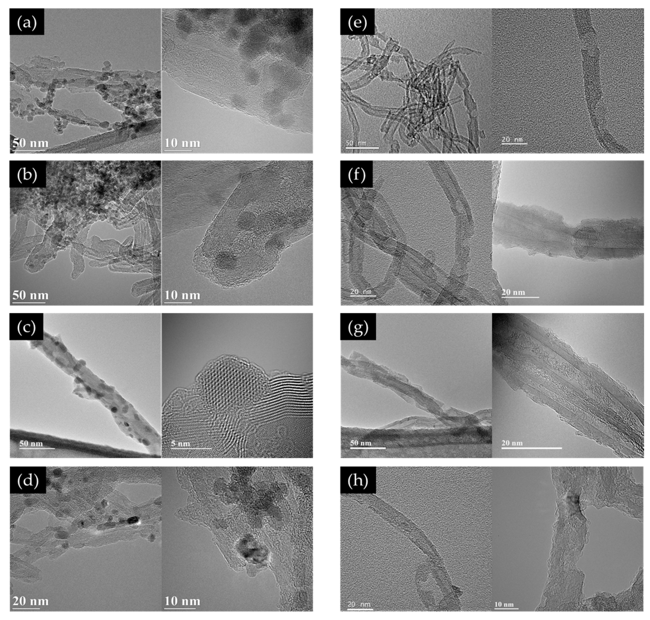
3.1. TEM
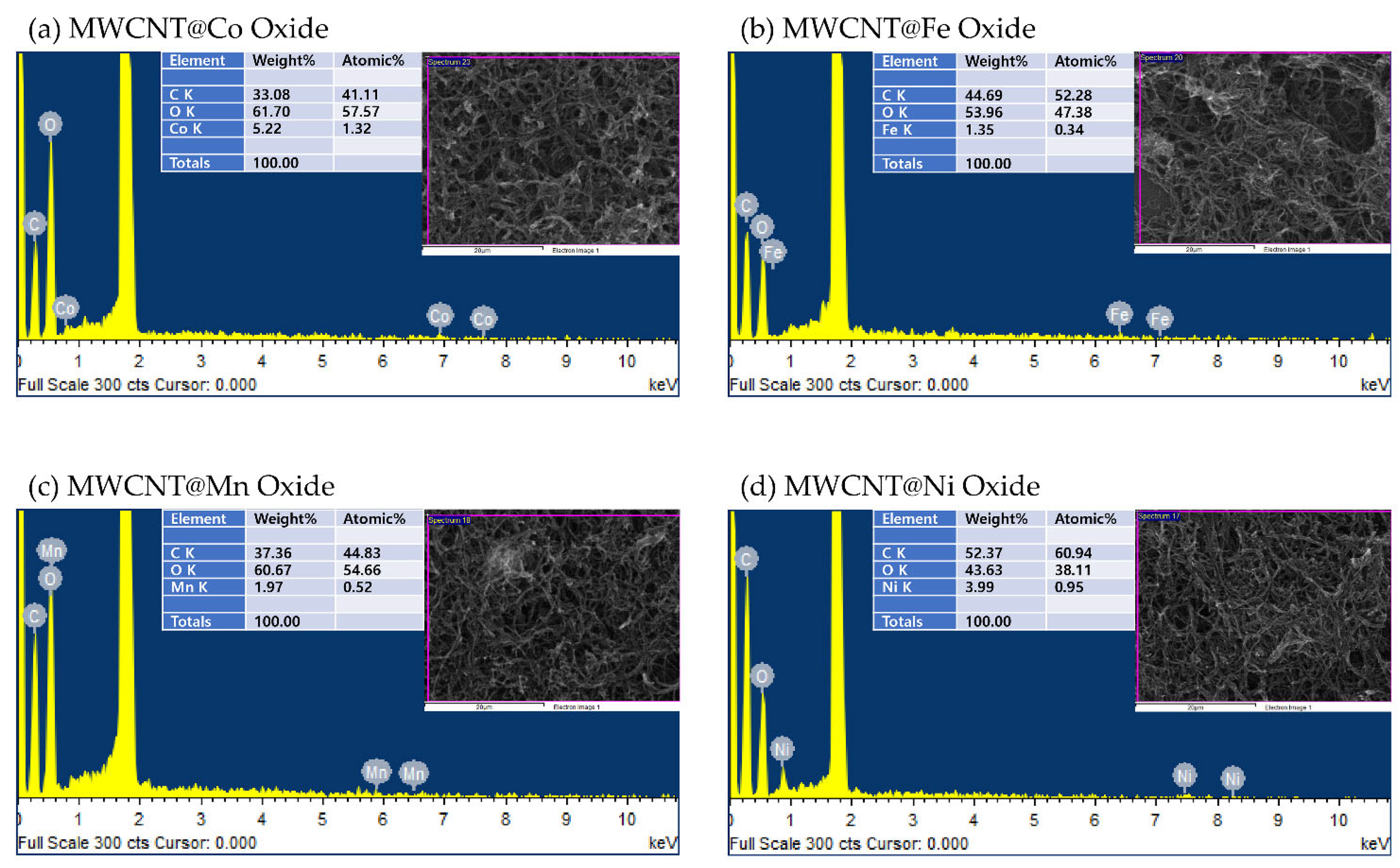
3.2. SEM/EDS
3.3. XRD
3.4. XPS
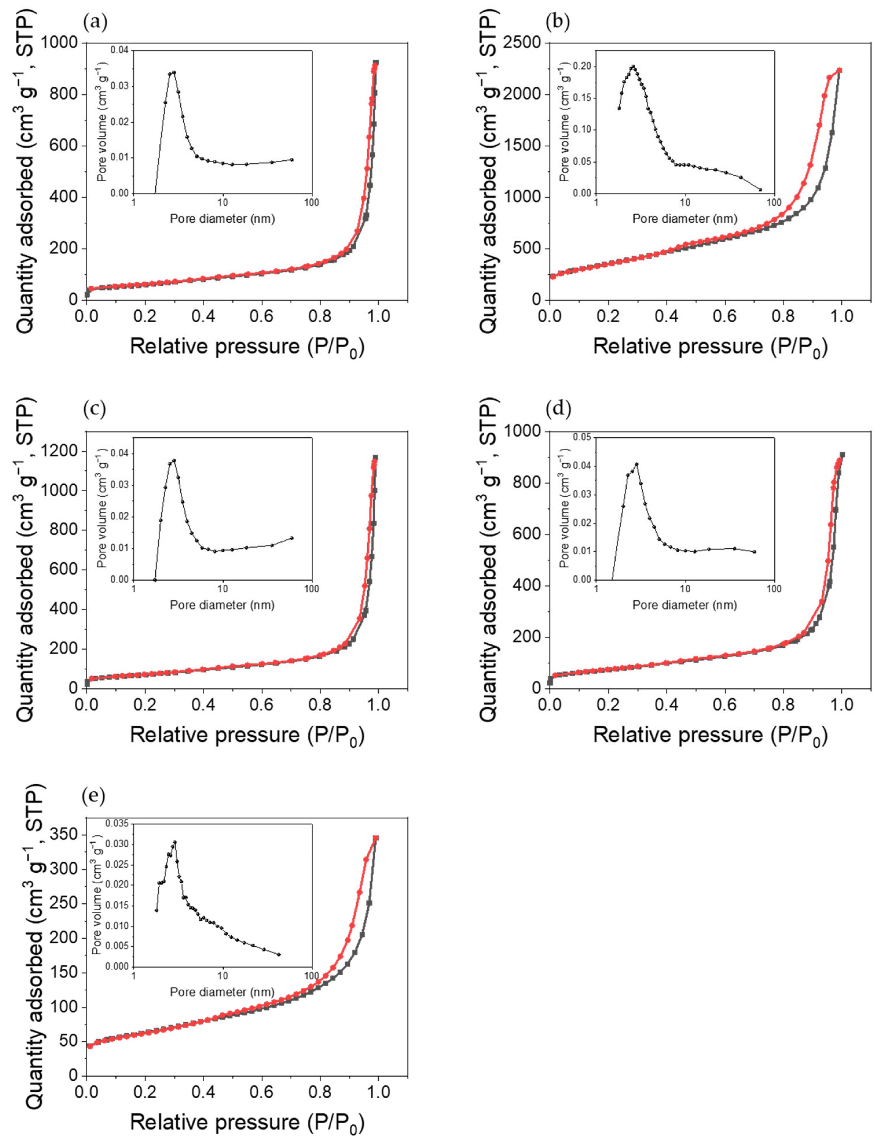
3.5. Specific Surface Area Analysis
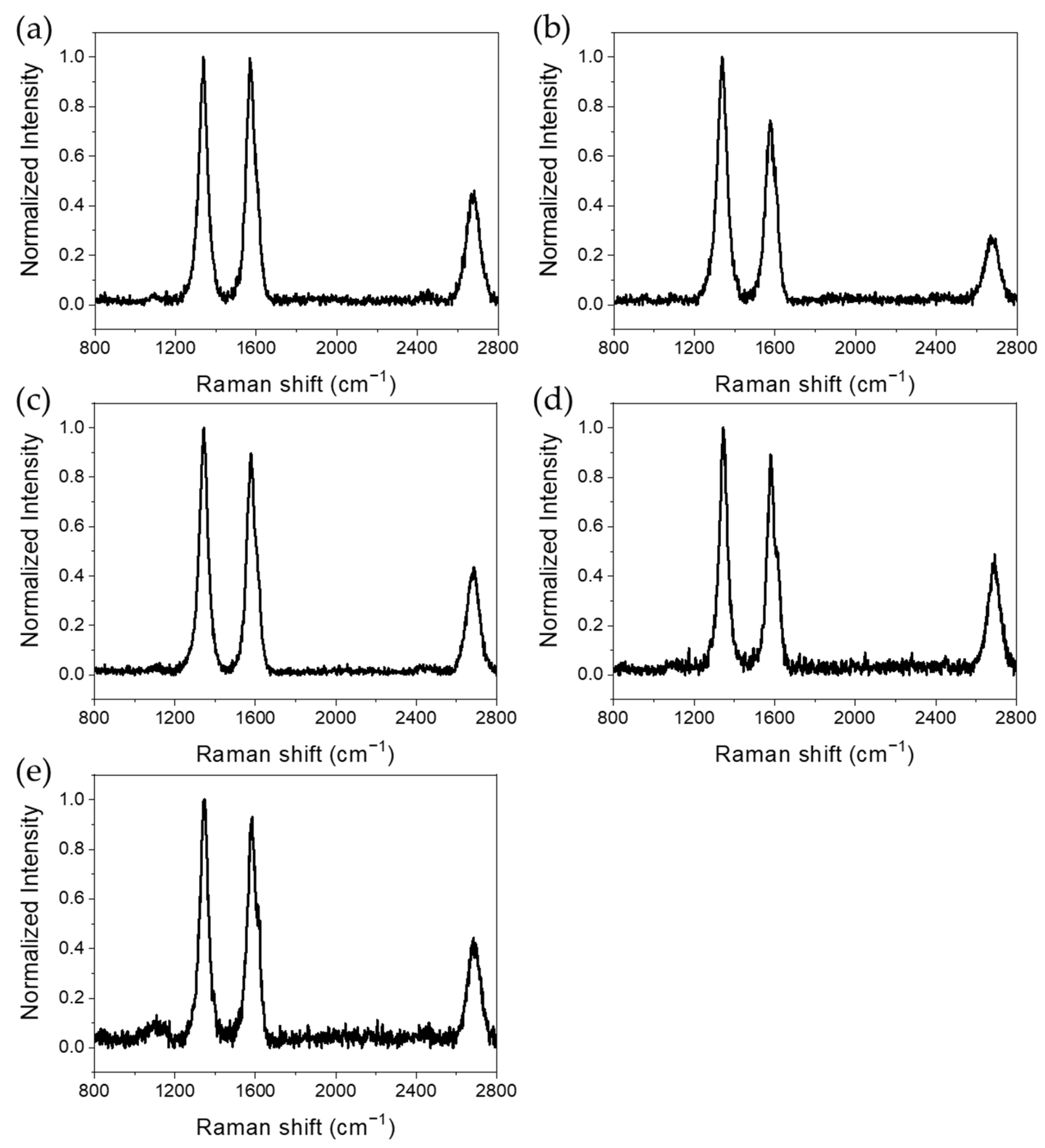
3.6. Raman Spectroscopy
3.7. Electrical Conductivity
4. Conclusions
Author Contributions
Funding
Institutional Review Board Statement
Informed Consent Statement
Data Availability Statement
Conflicts of Interest
References
- Ando, Y.; Zhao, X.; Shimoyama, H.; Sakai, G.; Kaneto, K. Physical Properties of Multiwalled Carbon Nanotubes. Int. J. Inorg. Mater. 1999, 1, 77–82. [Google Scholar] [CrossRef]
- Li, J.; Stevens, R.; Delzeit, L.; Ng, H.T.; Cassell, A.; Han, J.; Meyyappan, M. Electronic Properties of Multiwalled Carbon Nanotubes in an Embedded Vertical Array. Appl. Phys. Lett. 2002, 81, 910–912. [Google Scholar] [CrossRef] [Green Version]
- Yang, D.J.; Zhang, Q.; Chen, G.; Yoon, S.F.; Ahn, J.; Wang, S.G.; Zhou, Q.; Wang, Q.; Li, J.Q. Thermal Conductivity of Multiwalled Carbon Nanotubes. Phys. Rev. B 2002, 66, 165440. [Google Scholar] [CrossRef] [Green Version]
- Qin, F.; Brosseau, C. A Review and Analysis of Microwave Absorption in Polymer Composites Filled with Carbonaceous Particles. J. Appl. Phys. 2012, 111, 4. [Google Scholar] [CrossRef]
- Hwang, S.; Il Park, N.; Choi, Y.J.; Lee, S.M.; Han, S.Y.; won Chung, D.; Lee, S. PEDOT:PSS Nanocomposite via Partial Intercalation of Monomer into Colloidal Graphite Prepared by in-Situ Polymerization. J. Ind. Eng. Chem. 2019, 76, 116–121. [Google Scholar] [CrossRef]
- Iijima, S. Helical Microtubules of Graphitic Carbon. Nature 1991, 354, 56–58. [Google Scholar] [CrossRef]
- Thess, A.; Lee, R.; Nikolaev, P.; Dai, H.; Petit, P.; Robert, J.; Xu, C.; Lee, Y.H.; Kim, S.G.; Rinzler, A.G.; et al. Crystalline Ropes of Metallic Carbon Nanotubes. Science 1996, 273, 483–487. [Google Scholar] [CrossRef] [Green Version]
- Guo, T.; Nikolaev, P.; Thess, A.; Colbert, D.T.; Smalley, R.E. Catalytic Growth of Single-Walled Manotubes by Laser Vaporization. Chem. Phys. Lett. 1995, 243, 49–54. [Google Scholar] [CrossRef]
- Ebbesen, T.W.; Ajayan, P.M. Large-Scale Synthesis of Carbon Nanotubes. Nature 1992, 358, 220–222. [Google Scholar] [CrossRef]
- Iijima, S.; Ajayan, P.M.; Ichihashi, T. Growth Model for Carbon Nanotubes. Phys. Rev. Lett. 1992, 69, 3100–3103. [Google Scholar] [CrossRef]
- Kong, J.; Soh, H.T.; Cassell, A.M.; Quate, C.F.; Dai, H. Synthesis of Individual Single-Walled Carbon Nanotubes on Patterned Silicon Wafers. Nature 1998, 395, 878–881. [Google Scholar] [CrossRef]
- Cassell, A.M.; Raymakers, J.A.; Kong, J.; Dai, H. Large Scale CVD Synthesis of Single-Walled Carbon Nanotubes. J. Phys. Chem. B 1999, 103, 6484–6492. [Google Scholar] [CrossRef]
- Li, W.Z.; Xie, S.S.; Qian, L.X.; Chang, B.H.; Zou, B.S.; Zhou, W.Y.; Zhao, R.A.; Wang, G. Large-Scale Synthesis of Aligned Carbon Nanotubes. Science 1996, 274, 1701–1703. [Google Scholar] [CrossRef] [PubMed]
- Liu, X.M.; Huang, Z.d.; Oh, S.w.; Zhang, B.; Ma, P.C.; Yuen, M.M.F.; Kim, J.K. Carbon Nanotube (CNT)-Based Composites as Electrode Material for Rechargeable Li-Ion Batteries: A Review. Compos. Sci. Technol. 2012, 72, 121–144. [Google Scholar] [CrossRef]
- Zuo, W.; Wang, C.; Li, Y.; Liu, J. Directly Grown Nanostructured Electrodes for High Volumetric Energy Density Binder-Free Hybrid Supercapacitors: A Case Study of CNTs//Li4Ti5O12. Sci. Rep. 2015, 5, 7780. [Google Scholar] [CrossRef] [Green Version]
- Vo, T.S.; Hossain, M.M.; Jeong, H.M.; Kim, K. Heavy Metal Removal Applications Using Adsorptive Membranes. Nano Converg. 2020, 7, 36. [Google Scholar] [CrossRef]
- Vo, T.S.; Vo, T.T.B.C.; Suk, J.W.; Kim, K. Recycling Performance of Graphene Oxide-Chitosan Hybrid Hydrogels for Removal of Cationic and Anionic Dyes. Nano Converg. 2020, 7, 4. [Google Scholar] [CrossRef] [Green Version]
- Choi, W.B.; Chung, D.S.; Kang, J.H.; Kim, H.Y.; Jin, Y.W.; Han, I.T.; Lee, Y.H.; Jung, J.E.; Lee, N.S.; Park, G.S.; et al. Fully Sealed, High-Brightness Carbon-Nanotube Field-Emission Display. Appl. Phys. Lett. 1999, 75, 3129. [Google Scholar] [CrossRef] [Green Version]
- Lee, N.S.; Chung, D.S.; Han, I.T.; Kang, J.H.; Choi, Y.S.; Kim, H.Y.; Park, S.H.; Jin, Y.W.; Yi, W.K.; Yun, M.J.; et al. Application of Carbon Nanotubes to Field Emission Displays. Diam. Relat. Mater. 2001, 10, 265–270. [Google Scholar] [CrossRef]
- Abouali, S.; Akbari Garakani, M.; Xu, Z.L.; Kim, J.K. NiCo2O4/CNT Nanocomposites as Bi-Functional Electrodes for Li Ion Batteries and Supercapacitors. Carbon 2016, 102, 262–272. [Google Scholar] [CrossRef]
- Gohier, A.; Laïk, B.; Kim, K.H.; Maurice, J.L.; Pereira-Ramos, J.P.; Cojocaru, C.S.; Van, P.T. High-Rate Capability Silicon Decorated Vertically Aligned Carbon Nanotubes for Li-Ion Batteries. Adv. Mater. 2012, 24, 2592–2597. [Google Scholar] [CrossRef] [PubMed] [Green Version]
- Zhang, K.; Lee, T.H.; Choi, M.J.; Rajabi-Abhari, A.; Choi, S.; Choi, K.S.; Varma, R.S.; Choi, J.W.; Jang, H.W.; Shokouhimehr, M. Electrochemical Activity of Samarium on Starch-Derived Porous Carbon: Rechargeable Li- and Al-Ion Batteries. Nano Converg. 2020, 7, 11. [Google Scholar] [CrossRef] [Green Version]
- Kim, Y.; Yun, J.; Shin, H.S.; Jung, K.N.; Lee, J.W. Synergistic Nanoarchitecture of Mesoporous Carbon and Carbon Nanotubes for Lithium–Oxygen Batteries. Nano Converg. 2021, 8, 17. [Google Scholar] [CrossRef] [PubMed]
- Tang, J.; Yang, G.; Zhang, Q.; Parhat, A.; Maynor, B.; Liu, D.; Din, L.C.; Zhou, O. Rapid and Reproducible Fabrication of Carbon Nanotube AFM Probes by Dielectrophoresis. Nano Lett. 2005, 5, 11–14. [Google Scholar] [CrossRef] [PubMed] [Green Version]
- Al-Saleh, M.H.; Sundararaj, U. Electromagnetic Interference Shielding Mechanisms of CNT/Polymer Composites. Carbon 2009, 47, 1738–1746. [Google Scholar] [CrossRef]
- Nam, I.W.; Lee, H.K.; Jang, J.H. Electromagnetic Interference Shielding/Absorbing Characteristics of CNT-Embedded Epoxy Composites. Compos. A Appl. Sci. Manuf. 2011, 42, 1110–1118. [Google Scholar] [CrossRef]
- Fugetsu, B.; Sano, E.; Sunada, M.; Sambongi, Y.; Shibuya, T.; Wang, X.; Hiraki, T. Electrical Conductivity and Electromagnetic Interference Shielding Efficiency of Carbon Nanotube/Cellulose Composite Paper. Carbon 2008, 46, 1256–1258. [Google Scholar] [CrossRef]
- Wang, L.L.; Tay, B.K.; See, K.Y.; Sun, Z.; Tan, L.K.; Lua, D. Electromagnetic Interference Shielding Effectiveness of Carbon-Based Materials Prepared by Screen Printing. Carbon 2009, 47, 1905–1910. [Google Scholar] [CrossRef]
- Kim, C.B.; Jeong, K.B.; Yang, B.J.; Song, J.-W.; Ku, B.-C.; Lee, S.; Lee, S.-K.; Park, C. Facile Supramolecular Processing of Carbon Nanotubes and Polymers for Electromechanical Sensors. Angew. Chem. 2017, 129, 16398–16403. [Google Scholar] [CrossRef]
- Peigney, A.; Laurent, C.; Flahaut, E.; Bacsa, R.R.; Rousset, A. Specific Surface Area of Carbon Nanotubes and Bundles of Carbon Nanotubes. Carbon 2001, 39, 507–514. [Google Scholar] [CrossRef] [Green Version]
- Ströbel, R.; Garche, J.; Moseley, P.T.; Jörissen, L.; Wolf, G. Hydrogen Storage by Carbon Materials. J. Power Sources 2006, 159, 781–801. [Google Scholar] [CrossRef]
- Lamari Darkrim, F.; Malbrunot, P.; Tartaglia, G.P. Review of Hydrogen Storage by Adsorption in Carbon Nanotubes. Int. J. Hydrogen Energy 2002, 27, 193–202. [Google Scholar] [CrossRef]
- Li, X.; Zhu, H.; Ci, L.; Xu, C.; Mao, Z.; Wei, B.; Liang, J.; Wu, D. Hydrogen Uptake by Graphitized Multi-Walled Carbon Nanotubes under Moderate Pressure and at Room Temperature. Carbon 2001, 39, 2077–2079. [Google Scholar] [CrossRef]
- Bacsa, R.; Laurent, C.; Morishima, R.; Suzuki, H.; Lay, M. Le Hydrogen Storage in High Surface Area Carbon Nanotubes Produced by Catalytic Chemical Vapor Deposition. J. Phys. Chem. B 2004, 108, 12718–12723. [Google Scholar] [CrossRef] [Green Version]
- Stafiej, A.; Pyrzynska, K. Adsorption of Heavy Metal Ions with Carbon Nanotubes. Sep. Purif. Technol. 2007, 58, 49–52. [Google Scholar] [CrossRef]
- Zhang, J.; Lee, J.K.; Wu, Y.; Murray, R.W. Photoluminescence and Electronic Interaction of Anthracene Derivatives Adsorbed on Sidewalls of Single-Walled Carbon Nanotubes. Nano Lett. 2003, 3, 403–407. [Google Scholar] [CrossRef]
- Yan, Y.; Zhang, M.; Gong, K.; Su, L.; Guo, Z.; Mao, L. Adsorption of Methylene Blue Dye onto Carbon Nanotubes: A Route to an Electrochemically Functional Nanostructure and Its Layer-by-Layer Assembled Nanocomposite. Chem. Mater. 2005, 17, 3457–3463. [Google Scholar] [CrossRef]
- Li, Q.; Zhang, J.; Yan, H.; He, M.; Liu, Z. Thionine-Mediated Chemistry of Carbon Nanotubes. Carbon 2004, 42, 287–291. [Google Scholar] [CrossRef]
- Gupta, V.K.; Kumar, R.; Nayak, A.; Saleh, T.A.; Barakat, M.A. Adsorptive Removal of Dyes from Aqueous Solution onto Carbon Nanotubes: A Review. Adv. Colloid Interface Sci. 2013, 193–194, 24–34. [Google Scholar] [CrossRef] [PubMed]
- Cao, Q.; Yu, Q.; Connell, D.W.; Yu, G. Titania/Carbon Nanotube Composite (TiO2/CNT) and Its Application for Removal of Organic Pollutants. Clean Technol. Environ. Policy 2013, 15, 871–880. [Google Scholar] [CrossRef]
- Bacsa, R.R.; Laurent, C.; Peigney, A.; Bacsa, W.S.; Vaugien, T.; Rousset, A. High Specific Surface Area Carbon Nanotubes from Catalytic Chemical Vapor Deposition Process. Chem. Phys. Lett. 2000, 323, 566–571. [Google Scholar] [CrossRef] [Green Version]
- Kim, D.H.; Waki, K. Crystal Defects on Multi-Walled Carbon Nanotubes by Cobalt Oxide. J. Nanosci. Nanotechnol. 2010, 10, 2375–2380. [Google Scholar] [CrossRef]
- Lehtinen, O.; Nikitin, T.; Krasheninnikov, A.V.; Sun, L.; Banhart, F.; Khriachtchev, L.; Keinonen, J. Characterization of Ion-Irradiation-Induced Defects in Multi-Walled Carbon Nanotubes. New J. Phys. 2011, 13, 073004. [Google Scholar] [CrossRef] [Green Version]
- Song, S.; Yang, H.; Rao, R.; Liu, H.; Zhang, A. Defects of Multi-Walled Carbon Nanotubes as Active Sites for Benzene Hydroxylation to Phenol in the Presence of H2O2. Catal. Commun. 2010, 11, 783–787. [Google Scholar] [CrossRef]
- Kim, T.H.; Kim, H.; Jang, H.J.; Lee, N.; Nam, K.H.; Chung, D.w.; Lee, S. Improvement of the Thermal Stability of Dendritic Silver-Coated Copper Microparticles by Surface Modification Based on Molecular Self-Assembly. Nano Converg. 2021, 8, 15. [Google Scholar] [CrossRef] [PubMed]
- Kim, T.H.; Cha, D.C.; Jeong, J.; Lee, S. Facile Fabrication of Carbon Nanotubes@CuO Composites by Microwave Method. Elastomers Compos. 2021, 56, 113–116. [Google Scholar] [CrossRef]
- Adil, S.; Kim, W.S.; Kim, T.H.; Lee, S.; Hong, S.W.; Kim, E.J. Defective, Oxygen-Functionalized Multi-Walled Carbon Nanotubes as an Efficient Peroxymonosulfate Activator for Degradation of Organic Pollutants. J. Hazard. Mater. 2020, 396, 122757. [Google Scholar] [CrossRef] [PubMed]
- Wepasnick, K.A.; Smith, B.A.; Schrote, K.E.; Wilson, H.K.; Diegelmann, S.R.; Fairbrother, D.H. Surface and Structural Characterization of Multi-Walled Carbon Nanotubes Following Different Oxidative Treatments. Carbon 2011, 49, 24–36. [Google Scholar] [CrossRef]
- Eslami, S.; Palomba, S. Integrated Enhanced Raman Scattering: A Review. Nano Converg. 2021, 8, 41. [Google Scholar] [CrossRef]
- Zhang, S.Y.; Li, T.T.; Zhu, H.L.; Zheng, Y.Q. Co3O4 Polyhedrons with Enhanced Electric Conductivity as Efficient Water Oxidation Electrocatalysts in Alkaline Medium. J. Mater. Sci. 2018, 53, 4323–4333. [Google Scholar] [CrossRef]
- Li, Z.; Cui, Y.; Chen, J.; Deng, L.; Wu, J. Fabrication of (Co,Mn)3O4/RGO Composite for Lithium Ion Battery Anode by a One-Step Hydrothermal Process with H2O2 as Additive. PLoS ONE 2016, 11, e0164657. [Google Scholar] [CrossRef] [PubMed]
- Antunes, E.F.; Lobo, A.O.; Corat, E.J.; Trava-Airoldi, V.J. Influence of Diameter in the Raman Spectra of Aligned Multi-Walled Carbon Nanotubes. Carbon 2007, 45, 913–921. [Google Scholar] [CrossRef]


| Purified MWCNTs | MWCNTs with Co3O4 NPs Removed | MWCNTs with Fe2O3 NPs Removed | MWCNTs with Mn3O4 NPs Removed | MWCNTs with NiO NPs Removed | |
|---|---|---|---|---|---|
| BET Specific Surface Area (m2/g) | 214.01 | 1273.37 | 253.52 | 266.12 | 218.18 |
| Difference in BET Specific Surface Area (m2/g) | 1059.36 | 39.51 | 52.11 | 4.17 |
| Type | G/D Ratio |
|---|---|
| Purified MWCNTs | 0.99 |
| MWCNTs with Co3O4 NPs removed | 0.74 |
| MWCNTs with Fe2O3 NPs removed | 0.90 |
| MWCNTs with Mn3O4 NPs removed | 0.89 |
| MWCNTs with NiO NPs removed | 0.92 |
| Purified MWCNTs | Multi-Vacancy-Defect MWCNTs | |
|---|---|---|
| Thickness of film (μm) | 14 | 10 |
| Resistance (Ω) | 14 | 22 |
| Conductivity (S/cm) | 51.0 | 45.5 |
Publisher’s Note: MDPI stays neutral with regard to jurisdictional claims in published maps and institutional affiliations. |
© 2022 by the authors. Licensee MDPI, Basel, Switzerland. This article is an open access article distributed under the terms and conditions of the Creative Commons Attribution (CC BY) license (https://creativecommons.org/licenses/by/4.0/).
Share and Cite
Kim, T.H.; Nam, D.H.; Kim, D.-H.; Leem, G.; Lee, S. Fabrication of Multi-Vacancy-Defect MWCNTs by the Removal of Metal Oxide Nanoparticles. Polymers 2022, 14, 2942. https://doi.org/10.3390/polym14142942
Kim TH, Nam DH, Kim D-H, Leem G, Lee S. Fabrication of Multi-Vacancy-Defect MWCNTs by the Removal of Metal Oxide Nanoparticles. Polymers. 2022; 14(14):2942. https://doi.org/10.3390/polym14142942
Chicago/Turabian StyleKim, Tae Hyeong, Dong Hwan Nam, Do-Hyun Kim, Gyu Leem, and Seunghyun Lee. 2022. "Fabrication of Multi-Vacancy-Defect MWCNTs by the Removal of Metal Oxide Nanoparticles" Polymers 14, no. 14: 2942. https://doi.org/10.3390/polym14142942
APA StyleKim, T. H., Nam, D. H., Kim, D.-H., Leem, G., & Lee, S. (2022). Fabrication of Multi-Vacancy-Defect MWCNTs by the Removal of Metal Oxide Nanoparticles. Polymers, 14(14), 2942. https://doi.org/10.3390/polym14142942