Article

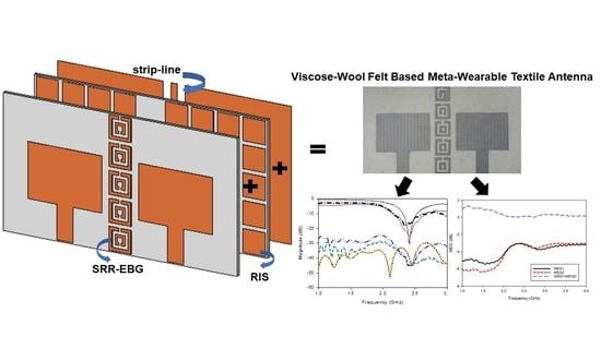
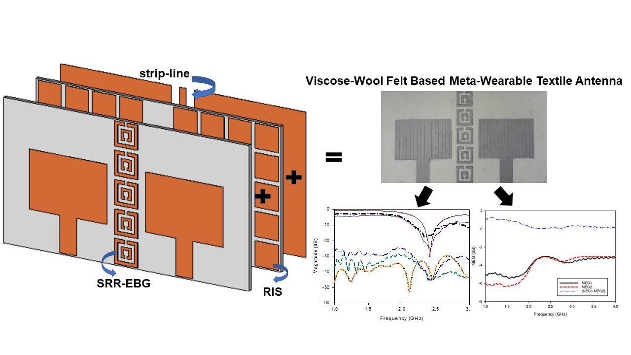
Combined RIS and EBG Surfaces Inspired Meta-Wearable Textile MIMO Antenna Using Viscose-Wool Felt

by
Amira Nur Suraya Shamsuri Agus
1,2,
Thennarasan Sabapathy
1,2,*,
Muzammil Jusoh
1,2,3,*,
Mahmoud A. Abdelghany
4,5,
Kabir Hossain
6,
Surentiran Padmanathan
1,2,
Samir Salem Al-Bawri
7 and
Ping Jack Soh
8
1
Advanced Communication Engineering (ACE), Centre of Excellence, Universiti Malaysia Perlis (UniMAP), Jalan Tiga, Pengkalan Jaya Business Centre, Kangar 01000, Malaysia
2
Faculty of Electronic Engineering Technology, Universiti Malaysia Perlis (UniMAP), Kampus Alam UniMAP Pauh Putra, Arau 02600, Malaysia
3
Department of General Educational Development, Faculty of Science and Information Technology (FSIT), Daffodil International University, Dhaka 1207, Bangladesh
4
Electrical Engineering Department, College of Engineering, Prince Sattam Bin Abdulaziz University, Wadi Addwasir 11991, Saudi Arabia
5
Department of Electrical Engineering, Faculty of Engineering, Minia University, Minia 61519, Egypt
6
Faculty of Engineering, Norwegian University of Science and Technology (NTNU), N-2815 Gjøvik, Norway
7
Space Science Centre, Climate Change Institute, Universiti Kebangsaan Malaysia, Bangi 43600, Malaysia
8
Centre for Wireless Communications (CWC), University of Oulu, 90014 Oulu, Finland
*
Authors to whom correspondence should be addressed.
Polymers 2022, 14(10), 1989; https://doi.org/10.3390/polym14101989
Submission received: 31 March 2022 / Revised: 3 May 2022 / Accepted: 6 May 2022 / Published: 13 May 2022
(This article belongs to the Special Issue High Performance Textiles)

Abstract

:
In this paper, we present a textile multiple-input–multiple-output (MIMO) antenna designed with a metamaterial inspired reactive impedance surface (RIS) and electromagnetic bandgap (EBG) using viscose-wool felt. Rectangular RIS was used as a reflector to improve the antenna gain and bandwidth to address well known crucial challenges—maintaining gain while reducing mutual coupling in MIMO antennas. The RIS unit cell was designed to achieve inductive impedance at the center frequency of 2.45 GHz with a reflection phase of 177.6°. The improved bandwidth of 170 MHz was achieved by using a square shaped RIS under a rectangular patch antenna, and this also helped to attain an additional gain of 1.29 dBi. When the antenna was implemented as MIMO, a split ring resonator backed by strip line type EBG was used to minimize the mutual coupling between the antenna elements. The EBG offered a sufficient band gap region from 2.37 GHz to 2.63 GHz. Prior to fabrication, bending analysis was carried out to validate the performance of the reflection coefficient (S11) and transmission coefficient (S21). The results of the analysis show that bending conditions have very little impact on antenna performance in terms of S-parameters. The effect of strip line supported SRR-based EBG was further analyzed with the fabricated prototype to clearly show the advantage of the designed EBG towards the mutual coupling reduction. The designed MIMO-RIS-EBG array-based antenna revealed an S21 reduction of −9.8 dB at 2.45 GHz frequency with overall S21 of <−40 dB. The results also indicated that the proposed SRR-EBG minimized the mutual coupling while keeping the mean effective gain (MEG) variations of <3 dB at the desired operating band. The specific absorption rate (SAR) analysis showed that the proposed design is not harmful to human body as the values are less than the regulated SAR. Overall, the findings in this study indicate the potential of the proposed MIMO antenna for microwave applications in a wearable format.

Graphical Abstract

1. Introduction

Antenna design for on-body applications has been popular in the past few decades. On-body antennas are mainly known for wireless body area networks (WBAN) and they are designed for various applications such as emergency rescue services, global positioning systems (GPS) [1] and health monitoring [2]. The antenna’s performance for the WBAN antenna is crucial because the antenna is placed close to the human body. As a result, some considerations are usually given to antennas for on-body applications where, (1) deformation analysis is usually carried out to check the performance of the antenna under various bending conditions (if the antenna is designed using flexible material), (2) specific absorption rate analysis is measured for the antenna with on-body application to verify the safety of the antenna’s electromagnetic (EM) effect on the human body and (3) antenna characteristics such as S11 and gain analysis with the on-body condition.
The choice of material becomes essential whenever an antenna is designed using flexible materials. Using polymer as a flexible material has been a common practice in wearable antenna designs [3,4]. The comprehensive review conducted in [4] has revealed that EM radiation characteristics of the antennas are affected hugely when the flexible polymer-based antennas undergo bending. In general, antenna designs consist of dielectric material as the substrate and conductive material as the patch that serves as the radiating element. Mixed metals with fabrics and conductive inks are some examples of conductive materials that have been adopted in previous works [5]. Polymers are widely been used as conductive materials in antenna design. They have been used as conductive threads [6], conductive polymers [7] and conductive textiles [8]. In addition, polymers are also commonly used as dielectric material or substrates used in antenna design. In [9], the substrate of the antenna has adopted the use of viscose-wool felt since it provides easier fabrication with sufficient flexibility while enabling strong adhesion with conductive textile Shieldit SuperTM. Apart from antenna design, polymers are also widely used in applications such as energy harvesting [10], supercapacitor [11,12,13], tissue engineering [14], immunosensor [15] and gas sensor [16]. As for the on-body application, flexible wideband antennas based on polymer technology have been proposed for medical imaging systems [17,18].
Recent research has shown that multiple-input–multiple-output (MIMO) antennas were also designed for WBAN applications to overcome the multipath fading that can happen due to the on-body communication links [19,20,21]. Reflections or scatterings that occur around the human body or the surrounding environment cause multipath fading. As a result, the reliability of multi-signal communication, and the performance of a WBAN system are reduced [22]. A diversity technique such as MIMO is needed to improve effective communication under the influence of multipath fading. Therefore, designing MIMO antenna with lower mutual coupling between antenna elements becomes significant to overcome the multipath fading issue. In the last decade, a few works that designed MIMO wearable antennas have been reported. In [23], a dumbbell-shaped stub on the ground was used for a wearable MIMO antenna to reduce mutual coupling. For wearable 5G devices, a folded-dipole MIMO antenna was developed in [20]. Likewise, an ultra-wide-band (UWB) MIMO antenna was designed for wearable devices with C-shaped slots to improve isolation [21]. Although these works have designed MIMO, the antennas designed are not directly used for on-body applications and the material used is not flexible. The design and analysis of the MIMO wearable antenna can be found in [24]. In that work, reported important results for on-body condition such as bending and specific absorption rate (SAR). Although the design outperforms other related works in terms of isolation with a limited gap between elements, the MIMO was not implemented with a common ground. MIMO designs need to have a single ground plane for MIMO to ensure the system has a common reference level (zero for ground) thus all the signals in the system can be interpreted properly [25].
The use of metamaterials or metasurfaces for on-body antenna design has found its interest to attain various performance improvements. Antenna characteristics such as gain, bandwidth and directivity are usually improved with the use of metamaterial. For instance, the artificial magnetic conductor (AMC) is used to improve gain and improve bandwidth [1,26]. In [27], a via-less EBG was designed for wearable antenna to increase the antenna gain and front-to-back ratio (FBR). In particular, minimal works have adopted metamaterial to solve the mutual coupling issue in flexible/textile MIMO antennas. A recently reported work [28] has adopted electromagnetic bandgap (EBG) to improve the isolation between dual-band MIMO antennas. However, this work lacks analyses such as deformation and SAR examination.
This research work presents a wearable textile MIMO antenna featuring two types of metasurface. First, a reactive impedance surface (RIS) array was designed to improve the antenna bandwidth and gain. Then, a split ring resonator (SRR) backed with strip line based EBG was implemented to reduce the mutual coupling between the multiple antennas. To the best of the authors’ knowledge, the use of different types of metasurface in a MIMO wearable antenna has never been investigated, especially when flexible materials are used. The metasurfaces and the antenna were designed using viscose-wool felt. The following sections present a comprehensive insight into the proposed work’s design stages.

2. Flexible Polymer-Based Meta-Wearable Antenna Design

Polymer-based flexible material was adopted for the proposed meta-wearable antenna. Flexible polymers have been studied in many recently investigated antenna research works [4]. The three main components of this work, namely RIS, EBG and the antenna, were all designed using a flexible polymer. Shieldit SuperTM with a thickness of 0.17 mm and a conductivity value of 1.18 × 10⁵ S/m was used as the ground plane of the RIS structure, EBG structure and the radiator. The commercially available Shieldit SuperTM is made from a rugged rip-stop polyester substrate, conductive nickel and copper plating. The other side of the sheet is coated with a non-conductive hot melt adhesive. This ensures the sheet is easily ironed onto the textile substrates. Meanwhile, a viscose-wool felt with a thickness of 3 mm, a dielectric constant of 1.44 and a loss tangent of 0.044 was employed as the substrate. Existing EM related works using this felt with Shiedlit SuperTM have shown good performance where the simulated and measured results were approximately the same [4,9,18]. The felt consists of 70% wool and 30% viscose which forms a good composition of fibers with a density of 0.25 gm/CC. This property ensured the Shieldit SuperTM can be easily ironed and attached to the viscose-wool felt. Apart from that, it meets British Standard 4060 for pressed wool felts for reliability and quality tests thus it was adopted as the substrate for the metasurfaces and antenna design. Computer Simulation Technology (CST)-Microwave Studio Suite (MWS) was used to model and simulate the metasurfaces and meta-inspired antenna. The analyses of these structures are reported in the following subsections.

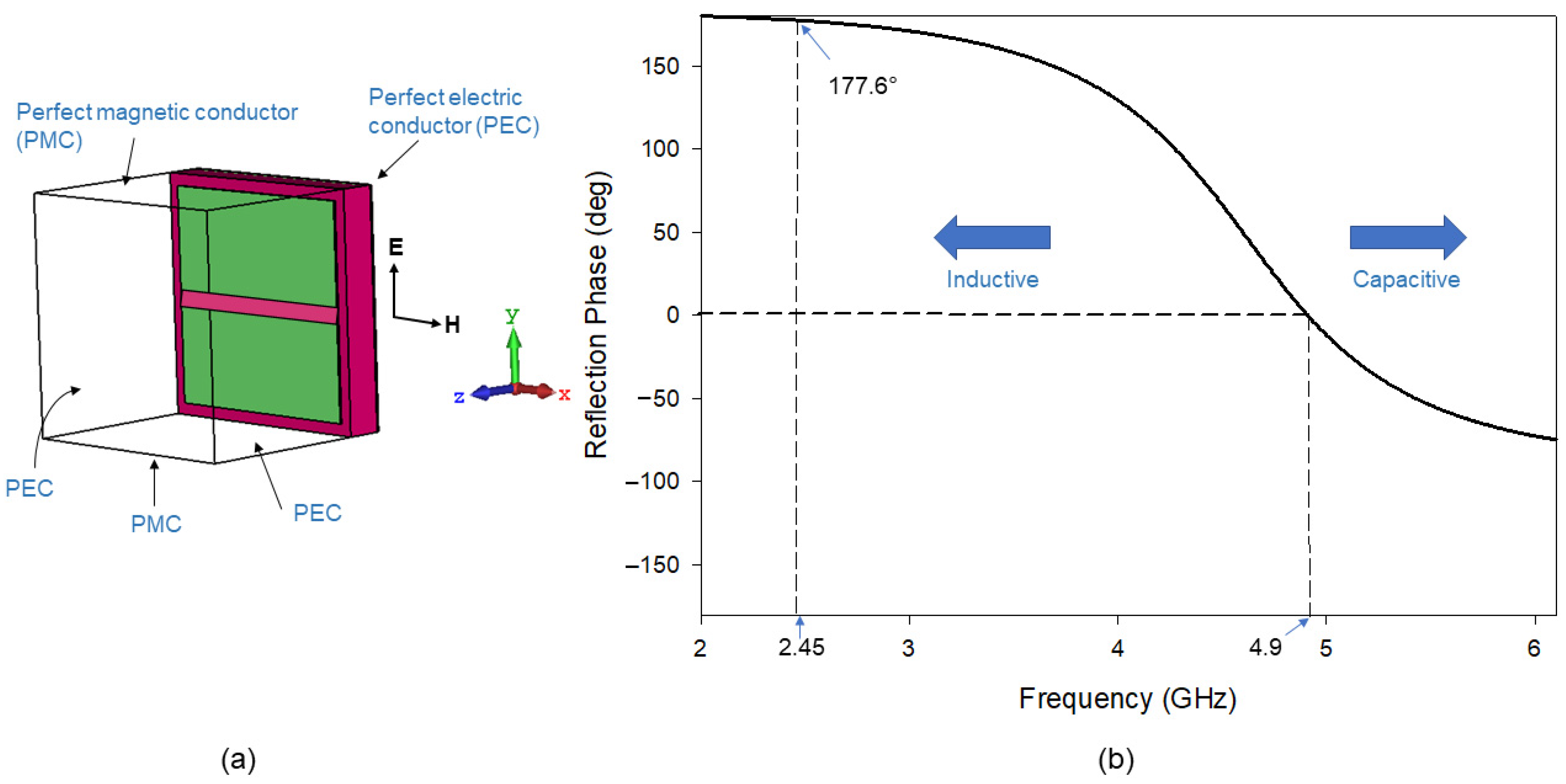
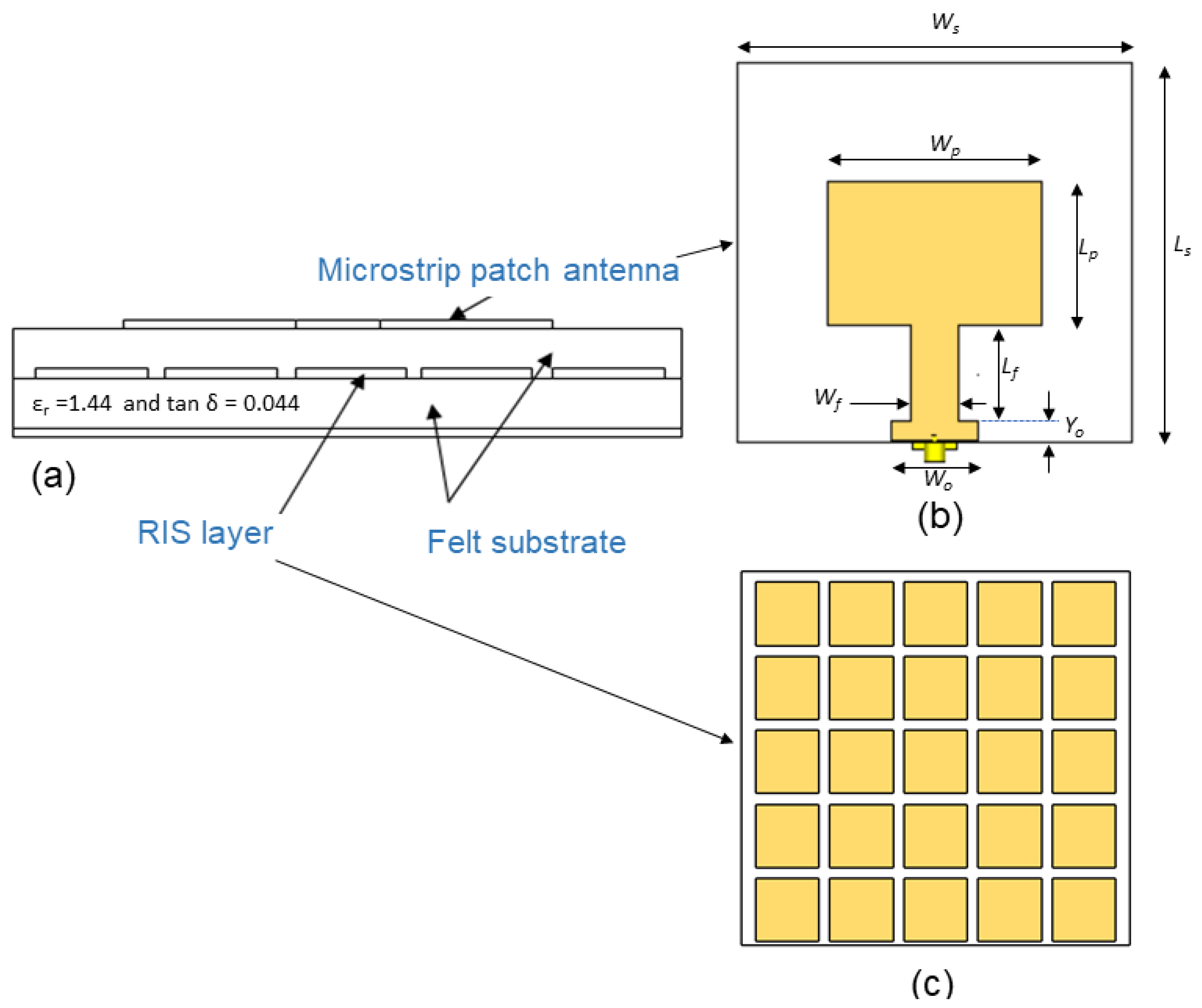
2.1. Reactive Impedance Surface Design with Rectangular Patch Antenna

In this work, a square-shaped RIS unit cell [29,30] with a dimension of a × a was modeled and simulated. The square shape was adopted due to its simplicity in design and fabrication of the antenna using flexible materials. The optimized dimension values, a is 18 mm and the gap between unit cell, g is 3 mm. As shown in Figure 1a, the unit cell RIS was backed by a perfect electric conductor (PEC) and interacted with transverse electromagnetic wave (TEM) from +z direction, establishing PEC and perfect magnetic conductor (PMC) boundaries perpendicular to the incident electric (E) and magnetic (H) fields. The resonant frequency of the RIS substrate is fRIS = 4.9 GHz, at which point the substrate acts like a PMC (open circuit). The RIS acts as an inductor below this resonance frequency. In particular, as shown in Figure 1b, at 2.45 GHz, the RIS acts as an inductor with a reflection phase at 177.6°. At this range, the surface can store magnetic energy, and this magnetic energy will compensate for the electric energy associated with a patch antenna.
Figure 2 presents a structure of a grounded dual-layer substrate with similar relative permittivity and height. We adopted a rectangular patch antenna in this design. At the same time, the proposed RIS metasurface was modeled as an array on the top of the lower layer, i.e., at the interface between both substrates.
The coaxial cable was connected at the edge of the line, whose width and length were set to match the antenna at 50 Ohm. These two parameters and the patch length were optimized to increase the gain, widen the bandwidth and miniaturize the antenna size at the frequency of 2.45 GHz. We optimized the patch antenna and RIS dimensions to attain the best performance of the MIMO antenna design which describes in the next section. Table 1 lists the optimized dimensions of the patch antenna.

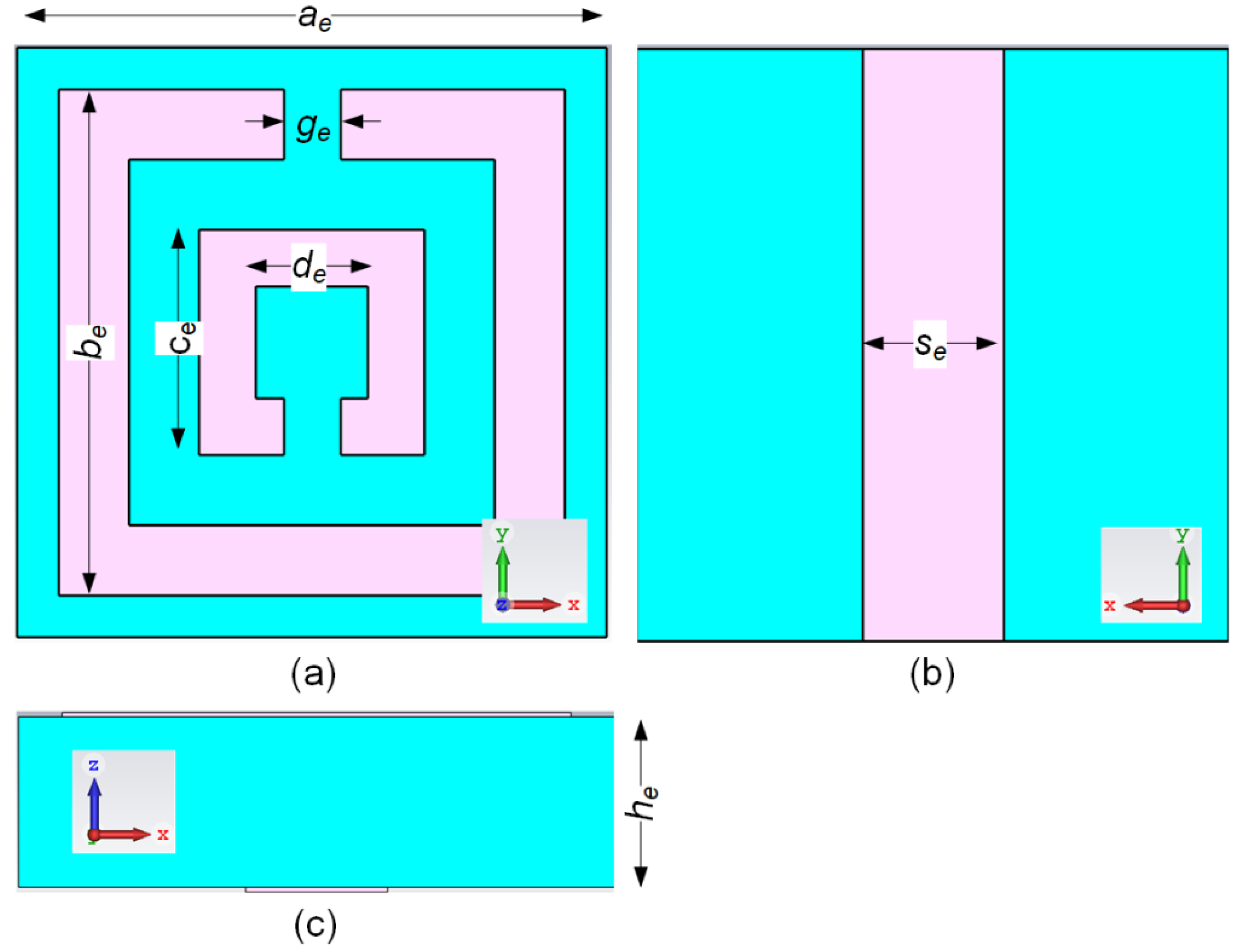
2.2. Electromagnetic Band-Gap Design

The EBG unit cell simulation was conducted using the Eigenmode Solver in CST MWS. The dispersion diagram method recommended in [31] was used to examine the properties of the EBG unit cell. We chose the SRR structure as it is via-less, thus making it easier for fabrication and integration with viscose-wool felt. The EBG structure with vias may increase the fabrication complexity when using textile-based materials. However, a via-less EBG without any splits on the structure could increase the frequency of mode I [27]. Therefore, the SRR-based EBG was implemented to maintain mode I at a lower frequency and mode II at a higher frequency to obtain a sufficient stop band. Figure 3 shows the unit cell structure of the EBG. The two split rings modelled in the SRR structure are capable of controlling mode I and mode II of the EBG. The parameters of the designed EBG are shown in Table 2.
The EBG unit cell simulation was essential to ensure the desired stop band or bandgap region is suitable for the developed MIMO antenna. Figure 4 shows the dispersion diagram of the Brillouin Triangle (Γ-X-M) [27] that corresponds to the Eigenmode simulation of the EBG unit cell shown in Figure 3. Mode I and II are the fundamental modes of transverse magnetic (TM) and the higher mode of transverse electric (TE) polarized waves, respectively. The black dotted lines represent the light lines (no dispersion case). EBG characteristic is obtained between mode I and mode II under the graph area of light-lines. From Figure 4 it can be seen that the bandgap region obtained is from 2.37 GHz to 2.63 GHz. This bandgap is sufficient for the operating frequency of the MIMO antenna, where the operating frequency range is from 2.4 GHz to 2.5 GHz. The EBG characteristic was expected to reduce the mutual coupling of the MIMO antenna result obtained in the previous section. In other words, the proposed EBG could reduce the S12 or S21 magnitude.

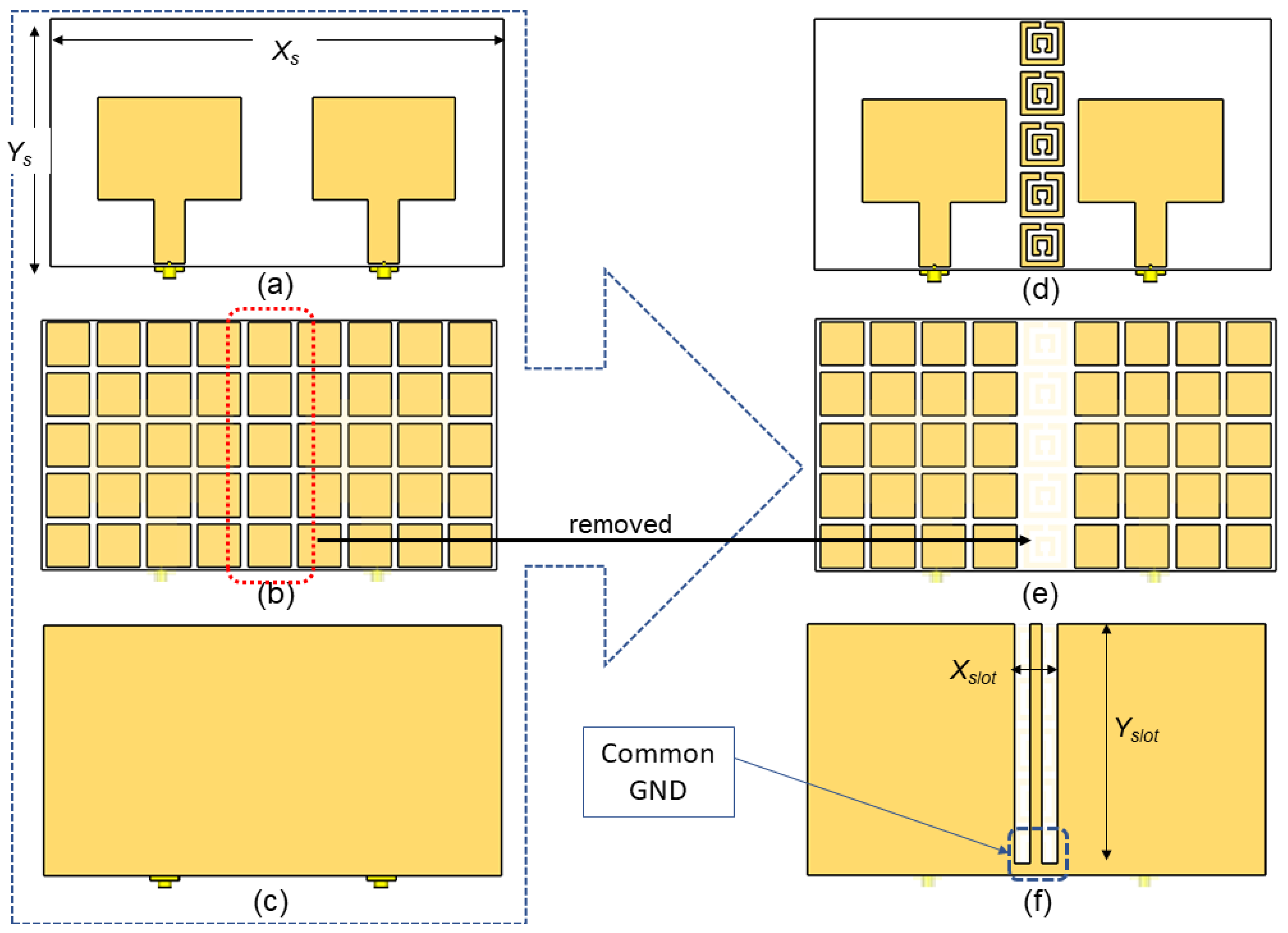
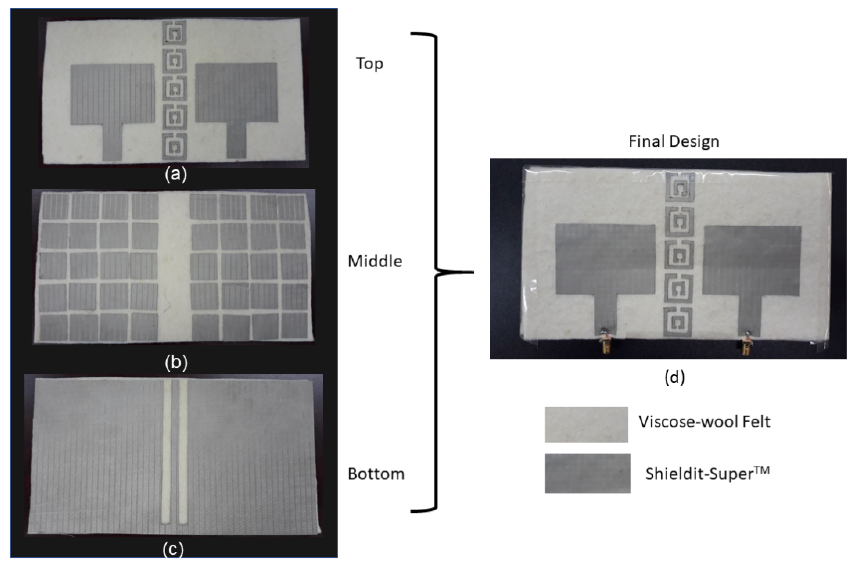
2.3. MIMO Antenna Design Geometry and Configurations

The MIMO-RIS-EBG antenna design flow is illustrated in Figure 5. Since the MIMO antenna consists of two antenna elements, the overall antenna size was increased to Xs × Ys where Xs = 190 mm and Ys = 104 mm. Apart from this, Lp was fine-tuned to 43 mm to obtain optimum performance in terms of S11 when the antenna works as MIMO. To enable strip line for the EBG, a slot was created on the ground plane with a size of Xslot × Yslot where Xslot = 18 mm and Yslot = 99 mm. The EBG array was placed between the antenna elements as shown in Figure 4. To accommodate the EBG array, the RIS array that overlaps with the EBG substrate was removed, as depicted in Figure 4e. Although the bottom layer of EBG has strip line, this should not create a direct split on the antenna’s ground plane. Therefore, a common ground plane was ensured at the edge of the strip line as shown in Figure 4f. This is because in a real system the signal should have a single/common ground (GND). Certainly, a direct split can improve the isolation of the antenna element, but this is not a recommended practice by [25].
The steps were used to fabricate the prototype as shown in Figure 6. These steps were adopted from the literature that used similar polymer and conductive materials [9,32]. After finalizing the modeling in the simulation, the structures were printed using computer aided design (CAD) software. The dielectric polymer material (viscose-wool felt) and conductive material (Shieldit SuperTM) of the prototype were then cut. An iron with medium heat was then used to paste the Shieldit SuperTM on the viscose-wool felt. Alternatively, the Shieldit SuperTM can be sewn to the viscose-wool felt. This could ensure the bonding between them remain strong even after washing or repeated bending. The final fabricated prototype is shown in Figure 7. The figure shows clearly the two layers of the antenna: the top layer with a patch antenna and EBG array (no patch is underneath this layer); the middle layer that consists of the RIS array; and the bottom layer that consists of the strip line that is associated with the EBG array of the top layer.

3. Results and Discussion

This section presents the related results at each stage of the design. First, the simulated results in terms of S11 and gain are presented for the single element patch antenna developed with the RIS. The rest of the section discusses the MIMO-RIS-EBG antenna results in various terms such as S-parameter, gain, radiation pattern and mutual coupling analysis.

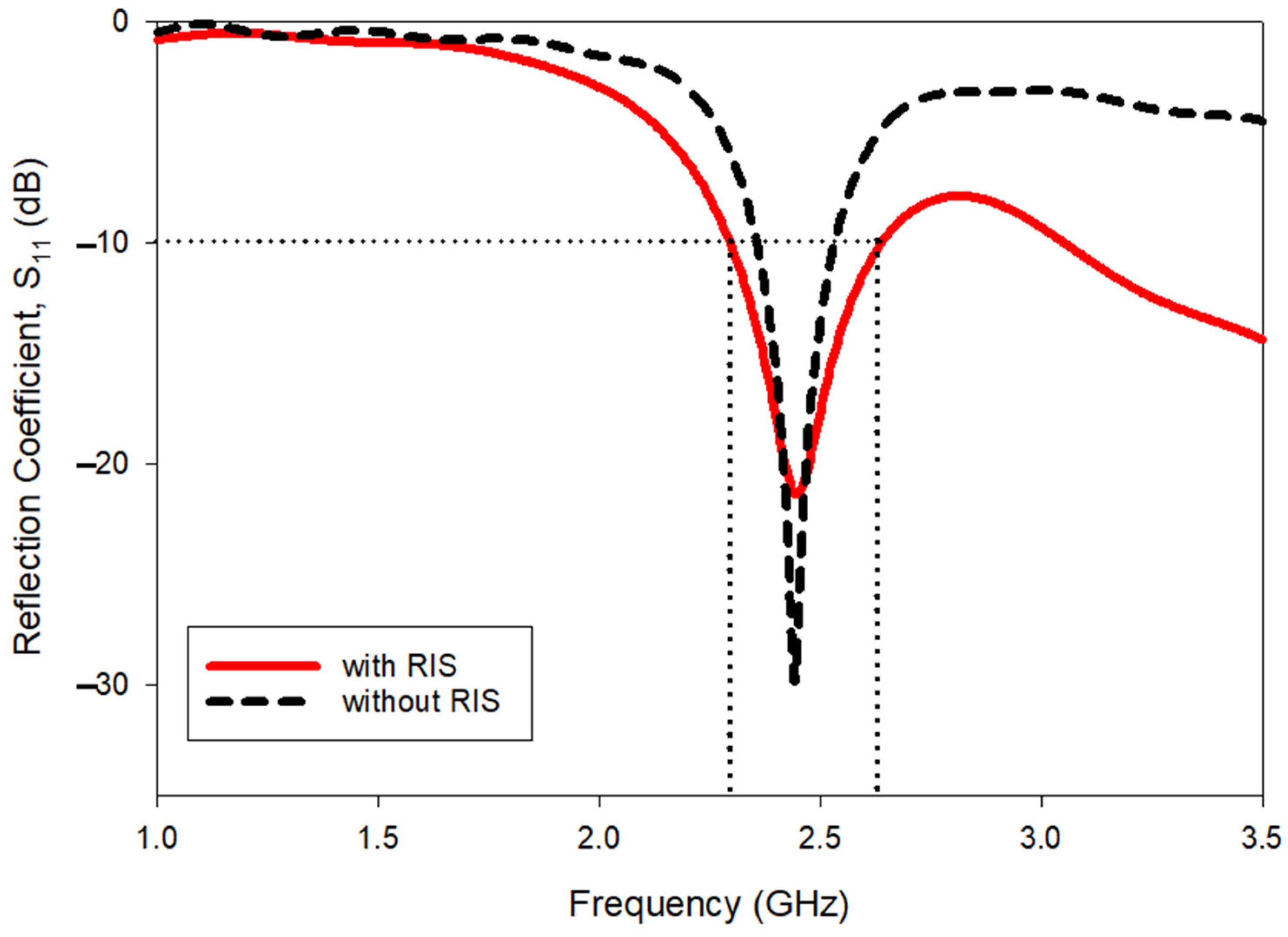
3.1. Advantages of RIS for Patch Antenna

From Figure 8, it is evident that the S11 bandwidth of a single patch antenna with RIS is 2.292 GHz–2.632 GHz (340 MHz). Meanwhile, the operating bandwidth without RIS is 2.354 GHz–2.535 GHz (181 MHz). Additional bandwidth of almost 170 MHz is obtained with the RIS. Therefore, it is evident that the use of RIS gives more significant greater benefits in terms of bandwidth enhancement.
Apart from this, the RIS also gives advantages in terms of size reduction. Without RIS, the length of the antenna Lp was 48 mm. With the RIS, the Lp could be reduced to 39.5 mm. Approximately 18% of the size reduction was attained with the use of RIS.
The radiation pattern is another important result that was investigated to see the advantages of using RIS. Figure 9 shows that the gain of the antenna with RIS is greater than the gain of the antenna without RIS. The attainable antenna gain without RIS is 4 dB, while the inclusive RIS layer provided an improved gain of 5.29 dB. This attribute was mainly contributed by the RIS layer when it acts as an inductor at 2.45 GHz. Meanwhile, the RIS surface stored magnetic energy, and this magnetic energy compensated for the electric energy associated with the patch antenna. This helped the EM radiation be further reflected toward the +z direction while the back-lobe radiation was reduced. Overall, an additional gain of 1.29 dB could be obtained with the use of RIS. It can be noted that the use of RIS not only improved the bandwidth and reduced the size, but also increased the antenna gain.

3.2. Performance Enhancement by Stripline Backed SRR-EBG

S-parameter results were then investigated for the final design (MIMO-RIS-EBG). Motivated by previous work, EBG is capable of reducing mutual coupling between the antenna [33]. In this work, we designed and analyzed a new EBG structure to deploy in a RIS based MIMO antenna. Therefore, it was necessary to investigate the effect of EBG cautiously. Additionally, the bottom part of EBG consists of a strip line, thus a careful analysis was carried out to indicate the effect of EBG solely on the performance enhancement in terms of mutual coupling reduction. Figure 10 shows a thorough study directed to see the difference of S21 result for two conditions as follows,
Condition 1: simulation result of MIMO with the top part of EBG (as shown in Figure 5c) was removed.
Condition 2: simulation result of MIMO with full part of the EBG, top and bottom part available.
The results in Figure 10 clearly show that the full model of the EBG with the stripline outperforms the antenna without the top EBG structure but with the stripline at the bottom. Without this analysis, one can claim that the S21 reduction may be due to the defected ground structure formed by the stripline. Approximately the use of SRR EBG backed by strip line reduced the S21 magnitude by 9.8 dB. Therefore, this investigation provides clear evidence of the EBG performance.
The measurements were conducted using the Agilent E5071C Network Analyzer (Agilent Technologies, Bayan Lepas, Penang, Malaysia) to validate the performance of the antenna. Figure 11 illustrates the experimental setup to measure the proposed antenna. To measure the S-parameters of the antenna, the coaxial probes from the antenna were connected to port 1 (P1) and port 2 (P2) of the network analyzer. The radiation pattern measurement was conducted with the aid of an Anechoic Chamber and a commercialized double-ridged horn antenna. The P2 of the network analyzer was connected to the antenna under test (AUT) which acts as the receiver. The double-ridged horn antenna (transmitter) was connected to P2. The data from the network analyzer were transferred to the computer using General Purpose Interface Bus (GPIB) cable.
Figure 12 shows the complete S-parameter results for both simulation and measurement. The simulated and measured S11 indicates a good agreement. The fabricated antenna resonant frequency is slightly shifted both in terms of S11 and S22. However, in terms of bandwidth both MIMO elements can cover the wireless body area network and Wi-Fi bandwidth. Apart from that, the measured S21 and S12 result indicating the performance of the antenna in terms of mutual coupling reduction also shows reasonable agreement with the simulated results. The measured S11 bandwidth is from 2.16 GHz to 2.66 GHz. Meanwhile, the measured S21 and S12 magnitudes are less than −40 dB at the frequency range from 2.36 to 2.52 GHz.
The 3D radiation pattern results shown in Figure 13 indicate that the EBG provides sufficient mutual coupling reduction to ensure the antenna gain is not affected. First, the single antenna gain was improved using RIS from 4 to 5.29 dB as shown in Figure 9. With the implementation of MIMO-RIS, the attainable antenna gain was 5.93 dB. Interestingly, the mutual coupling was further reduced using the proposed EBG, thus finally the MIMO-RIS-EBG antenna achieved 6.15 dB.
Figure 14 shows simulated and measured polar radiation pattern results for the MIMO-RIS-EBG antenna. The comparison with simulated results shows that the radiation pattern beamwidth is slightly affected for the antenna at port 2. The other antenna results exhibit a good agreement with the simulated results. The measured gain was also approximately 5.8 dB for antenna elements at both ports.

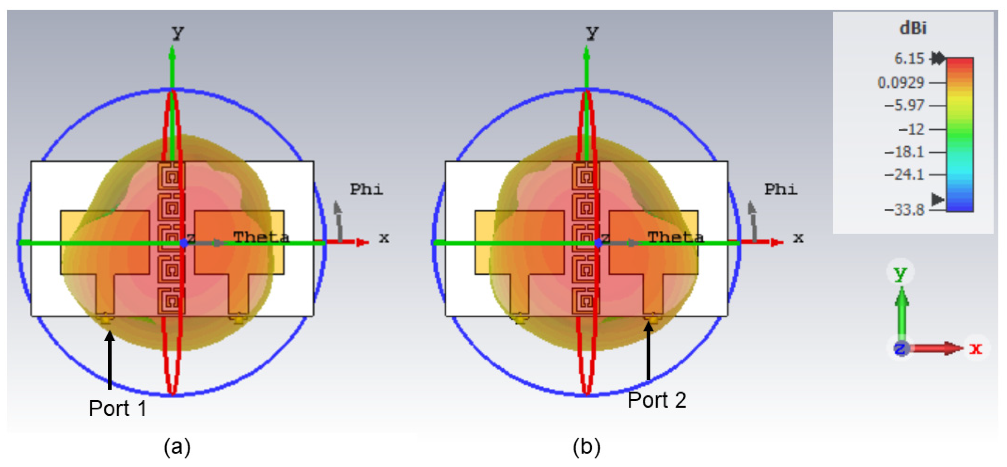
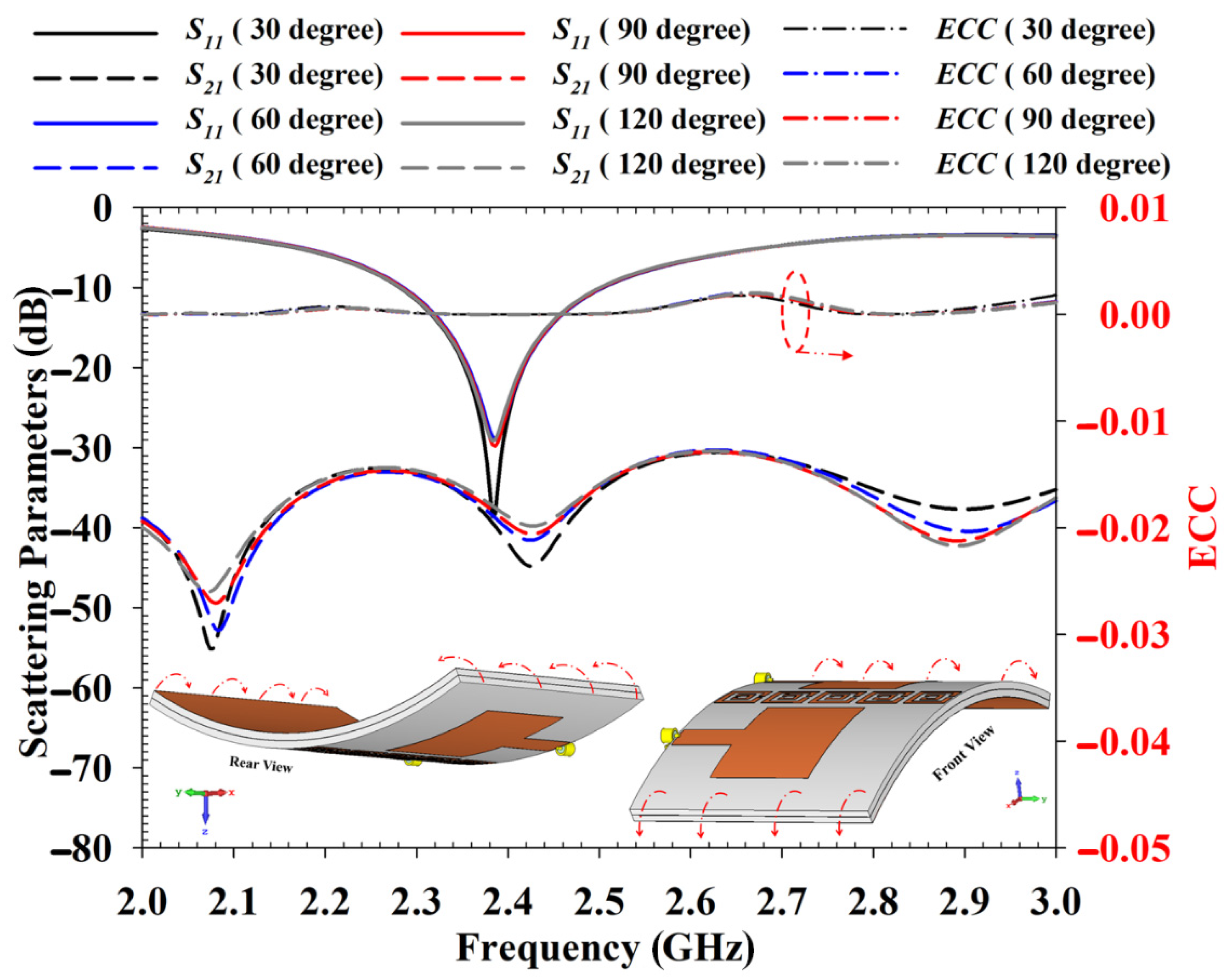
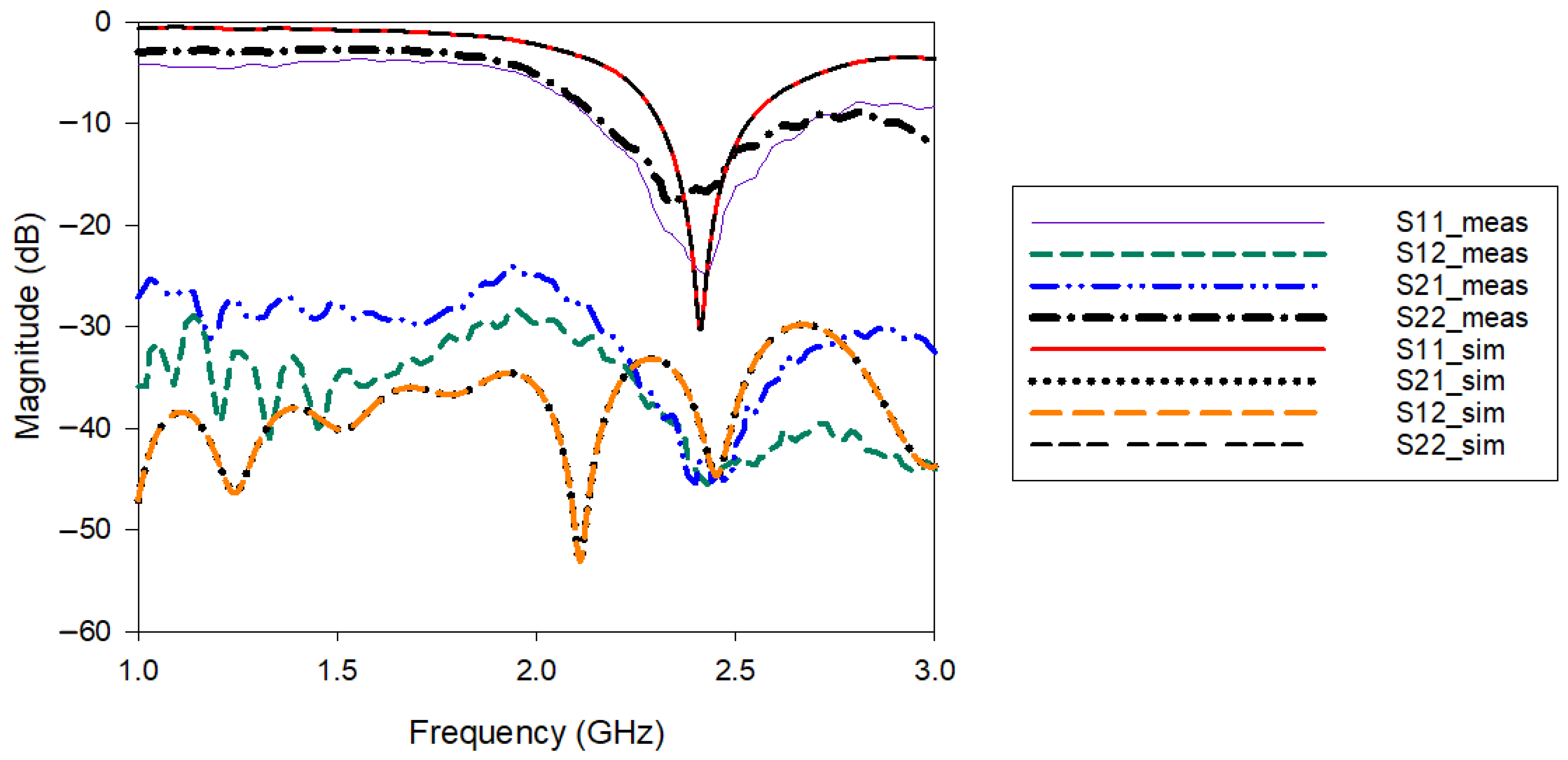
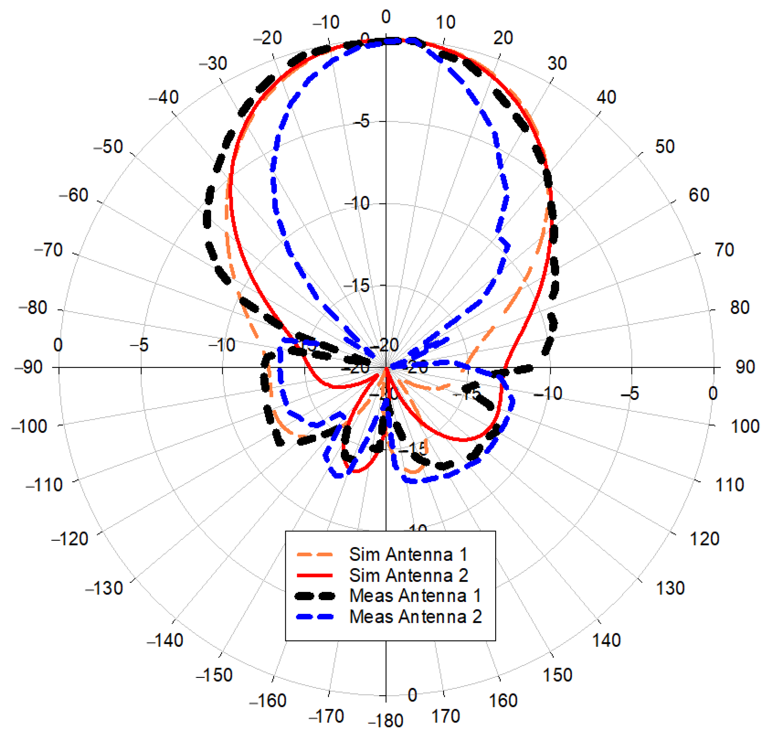
3.3. MIMO Properties of the Proposed Antenna

The performance of the proposed MIMO antenna was carried out in various terms, such as S11, S21 and radiation pattern. Additionally, the envelope correlation coefficient (ECC) and mean effective gain (MEG) properties of the antenna were also investigated [34,35]. ECC is a measure of how closely the antenna elements are coupled to each other, and it was calculated using the far-field radiation patterns using Equation (1). The ECC is given by,
ECC = |   4 π ( M i ( θ , ϕ ) ) × ( M j ( θ , ϕ ) ) d Ω | 2   4 π | ( M i ( θ , ϕ ) ) | 2 d Ω   4 π | ( M j ( θ , ϕ ) ) | 2 d Ω
where, Mi and Mj represent the antenna elements, ϕ represents the azimuth angle (0–360 degrees), θ represents elevation angle that pointed by the vector itself, M i ( θ , ϕ ) describes the far-field radiation pattern when element/antenna i is excited and M j ( θ , ϕ ) describes the 3D radiation pattern when element/antenna j is excited. Ω represents the solid angle. The acceptable value for ECC is <0.3 [36].
In addition to the ECC, the MEG ratios |MEGi/MEGj|, where i and j denote specific antenna elements that were computed to quantify the imbalanced levels of the diverse propagation branches [37]. The MEG is given by expression (2) where it was assumed that the channel is uniform Rayleigh with equal vertical and horizontal polarization power densities [36]. In other words, MEG then is equal to half of the radiation efficiency.
M E G i = 0.5 η i , r a d = 0.5 [ 1 j = 1 M | S i j | 2 ]
where ηi,rad is the radiation efficiency, M represents total antenna elements and | S i j | denotes the related scattering parameters.
K = | M E G 1 M E G 2 | < 3   d B
where K is the MEG variations and must be below 3 dB to have a comparable MEGs.
Figure 15 shows the MEG results of the proposed antenna. It can be noticed that the maximum MEG variation is at a 1.1 GHz frequency with 1.4 dB. At the desired operating range (2.4 to 2.5 GHz), the MEG variation is less than 3 dB. With this, good power balance and low diversity loss can be guaranteed.
The performance of the proposed antenna was also validated under deformation analysis. The deformation analysis was conducted with bending conditions applied to the antenna along the x and y axes. Figure 16 displays the bending analysis carried out on the x axis from 30 degrees to 120 degrees. It can be noted that the bending does not affect the antenna results critically. The changes on S11, S21 and ECC results are very small due to the bending condition, thus the antenna performance is expected not to be affected severely for on-body application.
On the other hand, Figure 17 shows the bending effect when the antenna is bent along the y axis. The analysis indicates that the antenna S11 is shifted when the bending range is increased. It also can be noted that for 120 degrees, the S21 result was primarily affected where it was reduced to −30 dB. Therefore, it can be concluded that the bending along the y axis can increase the antenna’s mutual coupling. The information in this analysis is important as when the antenna is deployed in the human body, the bending along the y axis should be avoided or minimized. The analyzed ECC value is less than 0.01 dB regardless of bending conditions, which indicates the mutual coupling reduction is effective with EBG.
Specific Absorption Rate (SAR) analysis was also conducted in addition to deformation analysis since the antenna could be used for wearable applications. The SAR results should be lower compared to the regulated SAR value. The regulated SAR value of 1.6 W/kg is taken over 1g of tissue that absorbs most EM energy and 2 W/kg is taken over 10 g of tissue that absorbs EM energy. The location of the antenna was selected to be on the chest of the body since the antenna size is considerably large with the MIMO method. Figure 18 and Figure 19 show that the peak rate of the SAR is 0.37 W/kg and 0.207 W/kg for 1 g and 10 g, respectively. The antenna at port 2 yields the maximum value for both SAR regulations. However, all SAR results are still below the regulated SAR value which is 1.6 W/kg taken over 1 g of tissue that absorbs most EM energy and 2 W/kg taken over 10 g of tissue that absorbs EM energy. These findings indicate that the proposed antenna is safe for on-body application. The use of RIS in this antenna also helps reduce the antenna’s back-lobe radiation pattern. Hence, properly implementation of the RIS structure helped reduce the SAR value.
A comparative analysis of the proposed high-performance textile antenna with previously investigated MIMO textile antenna is presented in Table 3 in terms of material used, operating frequency band, techniques used, antenna gain and isolation performance. The comparison shows that some works adopt materials that are difficult for fabrication, such as jeans as a substrate and copper sheet as the radiating element. None of the existing work has deployed two types of metamaterials in a single design to achieve different performance attributes as proposed in this work.

4. Conclusions

A metasurface-inspired textile MIMO antenna featuring both RIS and EBG surfaces was proposed and studied. The combined metasurface-inspired antenna prototype was fabricated using flexible polymer dielectric, viscose-wool felt as it enables easier fabrication with Shieldit SuperTM. The RIS array mainly helped increase the gain and bandwidth of the patch antenna. On the other hand, the proposed strip line backed SRR EBG exhibited band stop properties in the desired frequency range, from 2.4 GHz to 2.5 GHz. Via-less EBG was chosen as the via could complicate the fabrication process with the textile antenna. The implementation of the RIS and EBG into the antenna design was proven experimentally, where they improved the antenna gain and bandwidth reducing the mutual coupling effects. Measurements showed S11 bandwidth from 2.16 GHz to 2.66 GHz for magnitude <−10 dB, with a peak gain of 5.8 dBi. The S21 was <−40 dB over the frequency ranges from 2.36 to 2.52 GHz. Apart from this, the proposed antenna exhibits acceptable results in terms of MEG and ECC. The bending analysis also showed that the antenna performance effect is very minimal when bent at the x-axes. The overall findings indicate that the proposed design has the potential to be applied for wearable applications as the SAR analysis also showed a good result where the SAR value was less than 1.6 W/kg taken over 1 g of tissue and less than 2 W/kg taken over 10 g of tissue that absorbing EM energy.

Author Contributions

Conceptualization, A.N.S.S.A. and T.S.; design methodology, A.N.S.S.A. and P.J.S.; software, K.H. and M.A.A.; validation, M.J. and T.S.; formal analysis, A.N.S.S.A. and P.J.S.; investigation, S.P. and K.H.; design optimization, S.S.A.-B.; metamaterial characterization, A.N.S.S.A. and T.S; numerical calculation and data interpretation, M.A.A. and K.H.; resources, S.P.; writing—original draft preparation, A.N.S.S.A., T.S. and M.J.; writing—review and editing, T.S., S.P. and K.H.; visualization, K.H. and A.N.S.S.A.; supervision, T.S. and M.J.; project administration, S.S.A.-B.; funding acquisition, M.A.A. All authors have read and agreed to the published version of the manuscript.

Funding

This research received no external funding.

Institutional Review Board Statement

Not applicable.

Informed Consent Statement

Not applicable.

Data Availability Statement

The study did not report any data.

Conflicts of Interest

The authors declare no conflict of interest.

References

  1. Joshi, R.; Hussin, E.F.N.M.; Soh, P.J.; Jamlos, M.F.; Lago, H.; Al-Hadi, A.A.; Podilchak, S.K. Dual-Band, Dual-Sense Textile Antenna with AMC Backing for Localization Using GPS and WBAN/WLAN. IEEE Access 2020, 8, 89468–89478. [Google Scholar] [CrossRef]
  2. Shrestha, S.; Agarwal, M.; Ghane, P.; Varahramyan, K. Flexible Microstrip Antenna for Skin Contact Application. Int. J. Antennas Propag. 2012, 2012, 745426. [Google Scholar] [CrossRef]
  3. Kuang, Y.; Yao, L.; Yu, S.-H.; Tan, S.; Fan, X.-J.; Qiu, Y.-P. Design and Electromagnetic Properties of a Conformal Ultra Wideband Antenna Integrated in Three-Dimensional Woven Fabrics. Polymers 2018, 10, 861. [Google Scholar] [CrossRef] [Green Version]
  4. Ali Khan, M.U.; Raad, R.; Tubbal, F.; Theoharis, P.I.; Liu, S.; Foroughi, J. Bending Analysis of Polymer-Based Flexible Antennas for Wearable, General IoT Applications: A Review. Polymers 2021, 13, 357. [Google Scholar] [CrossRef]
  5. Almohammed, B.; Ismail, A.; Sali, A. Electro-Textile Wearable Antennas in Wireless Body Area Networks: Materials, Antenna Design, Manufacturing Techniques, and Human Body Consideration—A Review. Text. Res. J. 2021, 91, 646–663. [Google Scholar] [CrossRef]
  6. Huang, X.; Leng, T.; Zhang, X.; Chen, J.C.; Chang, K.H.; Geim, A.K.; Novoselov, K.S.; Hu, Z. Binder-Free Highly Conductive Graphene Laminate for Low Cost Printed Radio Frequency Applications. Appl. Phys. Lett. 2015, 106, 203105. [Google Scholar] [CrossRef]
  7. Sayem, A.S.M.; Simorangkir, R.B.V.B.; Esselle, K.P.; Hashmi, R.M. Development of Robust Transparent Conformal Antennas Based on Conductive Mesh-Polymer Composite for Unobtrusive Wearable Applications. IEEE Trans. Antennas Propag. 2019, 67, 7216–7224. [Google Scholar] [CrossRef]
  8. Corchia, L.; Monti, G.; Tarricone, L. Durability of Wearable Antennas Based on Nonwoven Conductive Fabrics: Experimental Study on Resistance to Washing and Ironing. Int. J. Antennas Propag. 2018, 2018, 1–8. [Google Scholar] [CrossRef]
  9. Hossain, K.; Sabapathy, T.; Jusoh, M.; Abdelghany, M.A.; Soh, P.J.; Osman, M.N.; Yasin, M.N.M.; Rahim, H.A.; Al-Bawri, S.S. A Negative Index Nonagonal CSRR Metamaterial-Based Compact Flexible Planar Monopole Antenna for Ultrawideband Applications Using Viscose-Wool Felt. Polymers 2021, 13, 2819. [Google Scholar] [CrossRef]
  10. Farooq, S.; Tahir, A.A.; Krewer, U.; Ul Haq Ali Shah, A.; Bilal, S. Efficient Photocatalysis through Conductive Polymer Coated FTO Counter Electrode in Platinum Free Dye Sensitized Solar Cells. Electrochim. Acta 2019, 320, 134544. [Google Scholar] [CrossRef]
  11. Rahman, S.u.; Röse, P.; Surati, M.; Shah, A.u.H.A.; Krewer, U.; Bilal, S. 3D Polyaniline Nanofibers Anchored on Carbon Paper for High-Performance and Light-Weight Supercapacitors. Polymers 2020, 12, 2705. [Google Scholar] [CrossRef]
  12. Ur Rahman, S.; Röse, P.; ul Haq Ali Shah, A.; Krewer, U.; Bilal, S. An Amazingly Simple, Fast and Green Synthesis Route to Polyaniline Nanofibers for Efficient Energy Storage. Polymers 2020, 12, 2212. [Google Scholar] [CrossRef]
  13. Ur Rahman, S.; Röse, P.; ul Haq Ali Shah, A.; Krewer, U.; Bilal, S.; Farooq, S. Exploring the Functional Properties of Sodium Phytate Doped Polyaniline Nanofibers Modified FTO Electrodes for High-Performance Binder Free Symmetric Supercapacitors. Polymers 2021, 13, 2329. [Google Scholar] [CrossRef]
  14. Rahman, S.U.; Bilal, S.; ul Haq Ali Shah, A. Synthesis and Characterization of Polyaniline-Chitosan Patches with Enhanced Stability in Physiological Conditions. Polymers 2020, 12, 2870. [Google Scholar] [CrossRef]
  15. Tanveer ul Haq, Z.; Anwar ul Haq Ali, S. Understanding the Adsorption of 1 NLB Antibody on Polyaniline Nanotubes as a Function of Zeta Potential and Surface Charge Density for Detection of Hepatitis C Core Antigen: A Label-Free Impedimetric Immunosensor. Colloids Surfaces A Physicochem. Eng. Asp. 2021, 626, 127076. [Google Scholar] [CrossRef]
  16. Bibi, S.; Ullah, H.; Ahmad, S.M.; Ali Shah, A.-H.; Bilal, S.; Tahir, A.A.; Ayub, K. Molecular and Electronic Structure Elucidation of Polypyrrole Gas Sensors. J. Phys. Chem. C 2015, 119, 15994–16003. [Google Scholar] [CrossRef]
  17. Alqadami, A.S.M.; Bialkowski, K.S.; Mobashsher, A.T.; Abbosh, A.M. Wearable Electromagnetic Head Imaging System Using Flexible Wideband Antenna Array Based on Polymer Technology for Brain Stroke Diagnosis. IEEE Trans. Biomed. Circuits Syst. 2019, 13, 124–134. [Google Scholar] [CrossRef]
  18. Hossain, K.; Sabapathy, T.; Jusoh, M.; Lee, S.-H.; Rahman, K.S.A.; Kamarudin, M.R. Negative Index Metamaterial-Based Frequency-Reconfigurable Textile CPW Antenna for Microwave Imaging of Breast Cancer. Sensors 2022, 22, 1626. [Google Scholar] [CrossRef]
  19. Khajeh-Khalili, F. A Broadband All-Textile Wearable MIMO Antenna for Wireless Telecommunication/Medical Applications. J. Text. Inst. 2020, 112, 2013–2020. [Google Scholar] [CrossRef]
  20. Zhu, L.; Hwang, H.S.; Ren, E.; Yang, G. High Performance MIMO Antenna for 5G Wearable Devices. In Proceedings of the 2017 IEEE International Symposium on Antennas and Propagation & USNC/URSI National Radio Science Meeting, San Diago, CA, USA, 9–14 July 2017; pp. 1869–1870. [Google Scholar]
  21. Li, Y.; Shen, H.; Zou, H.; Wang, H.; Yang, G. A Compact UWB MIMO Antenna for 4.5G/5G Wearable Device Applications. In Proceedings of the 2017 IEEE 6th Asia-Pacific Conference on Antennas and Propagation, APCAP 2017—Proceeding, Xi’an, China, 25 July 2018; Institute of Electrical and Electronics Engineers Inc.: New York, NY, USA, 2018; pp. 1–3. [Google Scholar]
  22. Abbasi, Q.H.; Ur-Rehman, M.; Qaraqe, K.; Alomainy, A. Advances in Body-Centric Wireless Communication: Applications and State-of-the-Art; Ur-Rehman, Q., Alomainy, A., Eds.; Institution of Engineering and Technology: Stevenage, UK, 2016; ISBN 9781849199896. [Google Scholar]
  23. Ramamohan, B.; Usha, S.; Ananth, P.; Lalitha, V.S.; Jaswanth, S. Design of Dumbbell-Shaped MIMO Antenna for Wearable Applications; Springer: Singapore, 2021; pp. 293–303. ISBN 9789811584381. [Google Scholar]
  24. Gupta, A.; Kansal, A.; Chawla, P. Design of a Wearable MIMO Antenna Deployed with an Inverted U-Shaped Ground Stub for Diversity Performance Enhancement. Int. J. Microw. Wirel. Technol. 2021, 13, 76–86. [Google Scholar] [CrossRef]
  25. Sharawi, M.S. Current Misuses and Future Prospects for Printed Multiple-Input, Multiple-Output Antenna Systems [Wireless Corner]. IEEE Antennas Propag. Mag. 2017, 59, 162–170. [Google Scholar] [CrossRef]
  26. Lago, H.; Soh, P.J.; Jamlos, M.F.; Shohaimi, N.; Yan, S.; Vandenbosch, G.A.E. Textile Antenna Integrated with Compact AMC and Parasitic Elements for WLAN/WBAN Applications. Appl. Phys. A Mater. Sci. Process. 2016, 122, 1059. [Google Scholar] [CrossRef]
  27. Ashyap, A.Y.I.; Elamin, N.I.M.; Dahlan, S.H.; Abidin, Z.Z.; See, C.H.; Majid, H.A.; AL-Fadhali, N.; Mukred, J.A.A.; Saleh, G.; Esmail, B.A.F. Via-Less Electromagnetic Band-Gap-Enabled Antenna Based on Textile Material for Wearable Applications. PLoS ONE 2021, 16, e0246057. [Google Scholar] [CrossRef]
  28. Roy, S.; Chakraborty, U. Mutual Coupling Reduction in a Multi-Band MIMO Antenna Using Meta-Inspired Decoupling Network. Wirel. Pers. Commun. 2020, 114, 3231–3246. [Google Scholar] [CrossRef]
  29. Chatterjee, J.; Mohan, A.; Dixit, V. Broadband Circularly Polarized H-Shaped Patch Antenna Using Reactive Impedance Surface. IEEE Antennas Wirel. Propag. Lett. 2018, 17, 625–628. [Google Scholar] [CrossRef]
  30. Mosallaei, H.; Sarabandi, K. Antenna Miniaturization and Bandwidth Enhancement Using a Reactive Impedance Substrate. IEEE Trans. Antennas Propag. 2004, 52, 2403–2414. [Google Scholar] [CrossRef] [Green Version]
  31. Ashyap, A.Y.I.; Dahlan, S.H.B.; Zainal Abidin, Z.; Abbasi, M.I.; Kamarudin, M.R.; Majid, H.A.; Dahri, M.H.; Jamaluddin, M.H.; Alomainy, A. An Overview of Electromagnetic Band-Gap Integrated Wearable Antennas. IEEE Access 2020, 8, 7641–7658. [Google Scholar] [CrossRef]
  32. Sabapathy, T.; Soh, P.J.; Jusoh, M. A Three-Year Improvement Assessment of Project-Based Learning for an Antennas and Propagation Course [Education Corner]. IEEE Antennas Propag. Mag. 2020, 62, 76–84. [Google Scholar] [CrossRef]
  33. Biswas, A.K.; Chakraborty, U. Reduced Mutual Coupling of Compact MIMO Antenna Designed for WLAN and WiMAX Applications. Int. J. RF Microw. Comput. Eng. 2019, 29, e21629. [Google Scholar] [CrossRef]
  34. Abdullah, M.; Kiani, S.H.; Iqbal, A. Eight Element Multiple-Input Multiple-Output (MIMO) Antenna for 5G Mobile Applications. IEEE Access 2019, 7, 134488–134495. [Google Scholar] [CrossRef]
  35. Li, Y.; Sim, C.-Y.-D.; Luo, Y.; Yang, G. Multiband 10-Antenna Array for Sub-6 GHz MIMO Applications in 5-G Smartphones. IEEE Access 2018, 6, 28041–28053. [Google Scholar] [CrossRef]
  36. Serghiou, D.; Khalily, M.; Singh, V.; Araghi, A.; Tafazolli, R. Sub-6 GHz Dual-Band 8 × 8 MIMO Antenna for 5G Smartphones. IEEE Antennas Wirel. Propag. Lett. 2020, 19, 1546–1550. [Google Scholar] [CrossRef]
  37. Ding, Y.; Du, Z.; Gong, K.; Feng, Z. A Novel Dual-Band Printed Diversity Antenna for Mobile Terminals. IEEE Trans. Antennas Propag. 2007, 55, 2088–2096. [Google Scholar] [CrossRef] [Green Version]
  38. Yan, S.; Soh, P.J.; Vandenbosch, G.A.E. Dual-Band Textile MIMO Antenna Based on Substrate-Integrated Waveguide (SIW) Technology. IEEE Trans. Antennas Propag. 2015, 63, 4640–4647. [Google Scholar] [CrossRef]
  39. Biswas, A.K.; Chakraborty, U. Compact wearable MIMO antenna with improved port isolation for ultra-wideband applications. IET Microw. Antennas Propag. 2019, 13, 498–504. [Google Scholar] [CrossRef]
  40. Biswas, A.K.; Chakraborty, U. Investigation on decoupling of wide band wearable multiple-input multiple-output antenna elements using microstrip neutralization line. Int. J. RF Microw. Comput. Eng. 2019, 29, e21723. [Google Scholar] [CrossRef]
Figure 1. RIS unit cell simulation: (a) RIS unit cell model and (b) reflection phase diagram.
Polymers 14 01989 g001
Figure 2. Schematic diagram of the proposed antenna and the RIS array: (a) side view of patch antenna with RIS, (b) First layer: front view of patch antenna and (c) Second layer: 5 × 5 array of RIS.
Polymers 14 01989 g002
Figure 3. EBG unit cell structure: (a) top view, (b) bottom view and (c) side view.
Polymers 14 01989 g003
Figure 4. EBG unit cell simulation and result (a) Dispersion diagram of SRR backed strip line EBG, (b) Brillouin Triangle simulation using Eigen mode solver.
Polymers 14 01989 g004
Figure 5. MIMO antenna using RIS: (a) front view, (b) second layer and (c) ground plane; and MIMO antenna using RIS and EBG: (d) front view, (e) second layer and (f) ground plane.
Polymers 14 01989 g005
Figure 6. Fabrication process of the meta-wearable textile antenna in this study.
Polymers 14 01989 g006
Figure 7. Fabrication MIMO-RIS-EBG antenna using viscose-wool felt and Shieldit-superTM: (a) front view of the antenna with substrate 1, (b) middle view of the antenna with substrate 2 and (c) bottom view of the antenna and (d) final antenna design.
Polymers 14 01989 g007
Figure 8. Reflection coefficient result comparison for MPA without RIS and with RIS.
Polymers 14 01989 g008
Figure 9. 3D radiation pattern results (a) patch antenna without RIS (b) patch antenna with RIS.
Polymers 14 01989 g009
Figure 10. Investigation on the effect of strip line (without EBG top layer) at the back of the antenna: (a) S-parameter results, (b) enlarged view of the S12 results at 2.45 GHz, (c) front view of the antenna without EBG top layer and (d) back view of the antenna without EBG top layer.
Polymers 14 01989 g010
Figure 11. Experimental setup to measure the proposed antenna performance.
Polymers 14 01989 g011
Figure 12. Simulated and measured S-parameters of the MIMO-RIS-EBG.
Polymers 14 01989 g012
Figure 13. The 3D radiation pattern results of MIMO-RIS-EBG (a) antenna 1 and (b) antenna 2.
Polymers 14 01989 g013
Figure 14. The polar radiation pattern results for MIMO-RIS-EBG.
Polymers 14 01989 g014
Figure 15. MEG results for MIMO-RIS-EBG.
Polymers 14 01989 g015
Figure 16. Bending analysis of the antenna at x axis.
Polymers 14 01989 g016
Figure 17. Bending analysis of the antenna at y-axis.
Polymers 14 01989 g017
Figure 18. SAR analysis for 1g tissue. (a) antenna 1, (b) antenna 2.
Polymers 14 01989 g018
Figure 19. SAR analysis for 10g tissue. (a) antenna 1, (b) antenna 2.
Polymers 14 01989 g019
Table 1. Parameters dimensions of the proposed antenna with RIS.
Para.Value (mm)Para.Value (mm)
Ws110.0Wf13.0
Ls106.0Lf26.8
Wp60.0Wo24.0
Lp40.0Yo5.5
Table 2. Parameter dimensions of the SRR backed with strip line EBG.
Para.Value(mm)Para.Value(mm)
ae21.0de4.0
ge2.0se5.0
be18.0he6.0
ce8.0
Table 3. Comparison of the proposed design with relevant previous work in the literature.
ReferenceMaterial UsedOperating Frequency (GHz)Metamaterial Structure/TechniqueAntenna Gain (dBi)Isolation (dB)Remarks
[38]Substrate: Viscose-wool felt
Conductive sheet/element:
Shieldit SuperTM
2.4 & 5Substrate integrated waveguide (SIW)NA20The investigation was conducted on MIMO antenna performance, but no specific method was used to reduce the mutual coupling
[39]Substrate: Jeans
Conductive sheet/element:
Copper sheet
2.74–12.08-shaped stub on a ground plane6.926Ultrawideband antenna design with 2 element MIMO
Integration of copper sheet with jeans was not shared
[40]Substrate: Jeans
Conductive sheet/element:
Copper sheet
3.5–8 Microstrip neutralization lineNA32Ultrawideband antenna design with 2 element MIMO
Integration of copper sheet with jeans was not shared
[19]Substrate: Standard felt
Conductive sheet/element:
Cotton fabric
1.1–8.6-7.540The use of cotton fabric as the patch in the antenna design is not practical.
While no specific mutual coupling reduction technique was used to achieve high isolation.
[28]Substrate: Jeans
Conductive sheet/element:
Copper sheet
1.5–3.8
4.2–6.2
Meanderline2–5 25–33 A Dual-band antenna was designed with 4 element MIMO
Integration of copper sheet with jeans was not shared
This workSubstrate: Viscose-wool felt
Conductive sheet/element:
Shieldit SuperTM
2.16–2.66 RIS
EBG
5.840RIS was used to miniaturize the antenna, increase the antenna gain (+1.29 dBi) and bandwidth.
Mutual coupling reduction in MIMO antenna
Publisher’s Note: MDPI stays neutral with regard to jurisdictional claims in published maps and institutional affiliations.

