Article

Development and Investigation of PEDOT:PSS Composition Coated Fabrics Intended for Microwave Shielding and Absorption

by
Vitalija Rubeziene
1,
Julija Baltusnikaite-Guzaitiene
1,*,
Ausra Abraitiene
2,
Audrone Sankauskaite
2,
Paulius Ragulis
3,
Gilda Santos
4 and
Juana Pimenta
5
1
Department of Textiles Physical-Chemical Testing, Center for Physical Sciences and Technology, 48485 Kaunas, Lithuania
2
Department of Textile Technologies, Center for Physical Sciences and Technology, 48485 Kaunas, Lithuania
3
Microwave Laboratory of Physical Technology Department, Center for Physical Sciences and Technology, 10257 Vilnius, Lithuania
4
CITEVE-Technological Centre for the Textile and Clothing Industries of Portugal, 4760-034 Vila Nova de Famalicão, Portugal
5
CeNTI-Centre for Nanotechnology and Smart Materials, 4760-034 Vila Nova de Famalicão, Portugal
*
Author to whom correspondence should be addressed.
Polymers 2021, 13(8), 1191; https://doi.org/10.3390/polym13081191
Submission received: 26 February 2021 / Revised: 22 March 2021 / Accepted: 1 April 2021 / Published: 7 April 2021
(This article belongs to the Special Issue Multifunctional Advanced Textile Materials)

Abstract

:
This study presents the investigation of the electromagnetic properties and resistance performance of electrically conductive fabrics coated with composition containing the conjugated polymer system poly(3,4-ethylenedioxythiophene)-polystyrene sulfonate (PEDOT:PSS). The developed fabrics were intended for electromagnetic radiation (EMR) shielding in microwave range and for absorbing microwaves in radar operating range, so as to act as radar absorbing materials (RAM). The measurements of reflection and transmission of the developed fabrics were performed in a frequency range of 2–18 GHz, which covers the defined frequencies relevant to the application. Four types of fabrics with different fiber composition (polyamide; polyamide/cotton; wool and para-aramid/viscose) were selected and coated with conductive paste using screen printing method. It was found that EMR shielding effectiveness (SE) as well as absorption properties depend not only the amount of conductive paste topped on the fabric, but also resides in the construction parameters of fabrics. Depending on such fabric structural parameters as density, mass per unit area, type of weave, a layer of shield (or coating) just sticks on the fabric surface or penetrates into fabric, changing the shield thickness and herewith turning SE results. Meanwhile, the fiber composition of fabrics influences mostly bonding between fibers and polymer coating. To improve the resistance performance of the developed samples, a conventional textile surface modification technique, atmospheric plasma treatment, was applied. Initially, before plasma treatment and after treatment the fabrics were evaluated regarding an aqueous liquid repellency test, measuring the contact angles for the water solvent. The influence of plasma treatment on resistance performance of coated fabrics was evaluated by subjecting the plasma treated samples and untreated samples to abrasion in the Martindale abrasion apparatus and to multiplex washing cycles. These investigations revealed that applied plasma treatment visibly improved abrasion resistance as a result of better adhesion of the coating. However, washing resistance increased not so considerably.

Graphical Abstract

1. Introduction

The reduction of electromagnetic radiation (EMR) impact is very important for the protection of people frequently using electrical and electronic devices which can emit electromagnetic waves with frequencies that are potential hazards to health. The International Agency for Research on Cancer (IARC) based on literature reports classifies radio frequency electromagnetic fields as group 2B, which includes factors probably carcinogenic to human [1]. The most utilized range is the microwave range, which can be defined as 1 −40 GHz, as most of the modern point to point, wireless, and satellite communications occupy this range. Electrically conductive woven or knitted fabrics with particular EMR shielding properties not only offer an opportunity to counter these threats, but also can be applicable to develop radar absorbing materials (RAM), for use in the field of stealth technology to disguise a vehicle or soldier from radar detection [2].
EMR shielding within the given frequency range can be provided by corresponding EMR reflection or absorption, and in the best case by reflection and absorption at the same time. In order to absorb or reflect EMR, materials must interact with either the electric or magnetic field of the radiation. Textile materials with incorporated conductive additives or coated with special conductive formulations are electrically conductive and therefore interact with the electric component of EMR [3].
The desired property of EMR shielding textile materials is low transmission that means high shielding effectiveness—SE (dB). According to the requirements of EMR shielding textiles on general use [4], conductive textiles can be classified in five grades from a fair grade to an excellent one: fair—7 dB ≥ SE ˃ 5 dB; moderate—10 dB ≥ SE ˃ 7 dB; good—20 dB ≥ SE ˃ 10 dB; very good—30 dB ≥ SE ˃ 20 dB; excellent—SE ˃ 30 dB. For EMR shielding applications, typically SE of at least 20 dB (indicates that 99% of the electromagnetic energy is reflected or absorbed by the material) is needed. SE of 30 dB indicates that 99.9% of the EM energy is reflected or absorbed by the material, with only 0.1% exiting the shielding material [5].
However, among EMR shielding textile materials only materials with substantial contribution to shielding from absorption have the potential to be used as radar absorbing materials (RAM). It is stated [6] that, depending on their practical use, such materials should be characterised by a high EMR absorption coefficient, even twice as high as their reflection coefficient within as wide a frequency band as possible. During the investigation of EMR shielding characteristics of the textile fabrics with different deposit of conductive additives [7] it was found that absorption dominated when the total EMR SE was below 20 dB and that reflectance dominated when EMR SE was above 20 dB. Hence, in order to be effective for a radar signature reduction application, SE must be not too high since such a textile material would be too reflective, resulting in the poor radar protection properties [8,9].
There are various techniques to provide the textiles with electrical conductivity and provide them with electromagnetic properties: introduction of electrically conductive yarns (carbon fibres, metal fibre); metallization of fabrics or yarns (voltaic, vacuum vaporisation); lamination or coating of conductive layers onto the fabric surface with metal particles, transparent organic metal oxides, carbon or inherently conducting polymers (ICPs).
Variable electrical conductivity, electromagnetic shielding, electrostatic properties, and in comparison, the low cost of ICPs, have led to the investigation of potential applications of these materials not only as corrosion protectors, sensors, polymer actuators, but also as electromagnetic shields and radar absorbers. In contrast to some commonly used metallic shielding materials, conducting polymers not only reflect but also absorb EMR in the microwave frequency range [10,11]. The dominant shielding characteristic of absorption other than that of reflection for metals render ICPs more promising materials in applications requiring not only high EMR shielding effectiveness but also shielding by absorption, such as in stealth technology.
The studies of textiles coated with conductive polymers [12,13] show that they are not highly effective as EMR shielding materials owing to their medium-level conductivity and therefore large skin depth. Textile fabrics with ICPs coatings mostly demonstrate shielding effectiveness (SE) not exceeding 20 dB in the microwave frequency range. Combine with fact that coatings are naturally thin, they cannot act as effective reflective barriers to EMR radiation. However, because they are highly absorptive in the microwave region, microwave-absorbing composite materials can be designed in conjunction with textiles.
The past works concerning EMR shielding with ICPs on textile fabrics are focused mainly on polyaniline (PANI) and polypyrrole (PPY) applications [7,10,13,14,15,16]. However, increasingly appears publications about application of other ICPs-PEDOT, for development of EMR shielding textiles [8].
The conjugated polymer system—poly(3,4-ethylenedioxythiophene)-polystyrene sulfonate (PEDOT:PSS) was chosen for this study because of its processability, stable electrical conductivity and low price in comparison with other ICPs. Also, PEDOT:PSS has other merits. For example, hydrogel particles offer excellent processing properties for the production of thin, transparent, conducting films [17]; coating with PEDOT:PSS does not affect the mechanical properties of the substrate and allows for them to be used as flexible and deformable substrates [18]. Whereas, due to the black color of polyaniline or polypyrrole, these ICPs are unlikely for developing conductive camouflage materials as the colour of these materials in VIS range should remain unchanged after coating.
The most common techniques [8] for applying ICPs on textiles are solution coating [19], in-situ polymerization [20], polymerization in supercritical fluid, electrochemical polymerization [21], electrostatic spinning [22], coating by screen printing [23], inkjet printing [24], or knife-over-roll technology [25]. The electrical properties of the conducting polymer-coated fabrics are influenced by various factors such as the concentration of reactants, deposit and thickness of the polymer coating, nature of the substrate surface, binding strength of coating to the textile surface, etc. [25,26]. Coating usually does not change the flexibility of the fabrics if it is applied in very thin layer, low mass and closed fabric structures. Most of the commercially available EMR shielding fabrics are produced by coating technologies and have very homogeneous and closed structures thus exhibiting satisfactory EMR shielding capabilities and isotropic behaviour [27].
Requirements for ideal EMR shielding textile or RAM textile fabric are not only high enough relevant EMR shielding effectiveness or absorption, over wide frequency range, but also stable electrical properties, resistance to washing, withstanding other impacts, which appear during the wear. However, current coating technologies do not provide sufficiently substantial bonding between textile substrate and ICPs layer. That leads to loss of conductivity of coated textile, caused by poor adhesion, during wear or after washing procedures. So, the resistance performance of fabrics coated with ICPs polymers needs to be improved. Most of the conductive coatings under studies are obtained by solution coating or in-situ polymerization and most commonly the materials so produced are used in development of electronic textiles, sensor [28,29]. However, the research into the development of the RAM textile and especially applying coating by screen printing or knife-over-roll technology, which allows the finish to be applied only on one surface/side of the material investigated, is not analyzed.
Plasma treatment is one of a several methods to improve bonding between the substrate and any polymeric coating. Plasma not only changes the surface morphology of the substrate but also binds active sites to the surface, rendering the surface active for subsequent reactions [30]. Plasma treatment is a useful method to introduce functional radicals onto the surfaces of material without changing material’s bulk properties [31]. Plasma technology has the advantages of convenience and environmental friendliness and more importantly, it has the capacity to activate the surface of substrates [32,33]. During plasma processing, many electrons, ions and metastable ions in the ion flow can break the molecular chain on the surface in a short time, increase the number of active groups and unsaturated bonds, and meanwhile play a certain etching effect [34]. Plasma treatment occurred only on the surface without affecting the elemental composition and macroscopic mechanical properties of the substrate [35]. Therefore, low-temperature plasma treatment could be employed to treat substrates before coating with conductive pastes.
The aim of this work was to develop and investigate the fabrics coated with formulation containing PEDOT:PSS, focusing on their electromagnetic properties and resistance performance. The developed fabrics are intended for electromagnetic radiation (EMR) shielding in microwave range likewise for absorbing microwaves in radar operating range, as to act as radar absorbing materials (RAM). Consequently, the measurements of reflection and transmission of developed textile fabrics were performed in a frequency range of 2–18 GHz, which covers the defined frequencies relevant to the application. To improve the resistance performance of developed samples, a conventional textile surface modification technique, i.e., atmospheric plasma treatment, was used and the plasma effects were studied.

2. Materials and Methods

2.1. Materials and Their Treatment

Four groups of samples were manufactured for this research work where, for each group, different woven fabrics were used as the substrates, per Table 1.
Plasma pre-treatment: To achieve a better resistance performance of coated fabrics, plasma treatment before coating was used. An industrial scale Atmospheric Plasma Treatment System from Sigma Technologies, model 2M (Sigma Technologies Int’l, LLC, Tucson AZ, 85737 USA), was used. Three types of treatment were used: oxygen (O2), nitrogen (N2), and Corona (air). For oxygen and nitrogen, 45% of these gasses was used, which correspond a flow rate of 450 sccm, and 100% of a carrier gas (argon), which correspond a flow rate of 15,000 sccm. The power of 15kW and speed of 3.3Hz (ca 10 m/min) was applied.
Before and after plasma treatment, the fabrics were evaluated regarding an aqueous liquid repellency test (according to ISO 23232 standard [36]), known as the drop test, and by measuring the contact angles for the water solvent, using the tensiometer equipment. The aqueous repellency grade/level is the highest numbered test liquid which is not absorbed by the substrate surface. The higher the aqueous solution repellency grade, the better the resistance to staining by aqueous materials, especially liquid aqueous substances. The aqueous solution repellency grade of a substrate is the numerical value of the highest-numbered test liquid which will not wet the substrate within a period of (10 ± 2) s. a grade of zero (0) is assigned when the substrate fails the 98% water solution test liquid.
According to the results obtained after preliminary experiment with different plasma treatments it was concluded that the plasma treatment with corona is the best, since there was a significant improvement in the hydrophilicity for those samples (S1 and S3), which initially were rather hydrophobic—their repellency level was 3, presenting a high hydrophobicity. For the other two fabrics (S2 and S4), the initial repellency level was 0 due to their high hydrophilicity. fabrics (substrates). Therefore, for selected fabrics—substrates (Table 1), before coating with conductive composition plasma treatment with corona (2 passages) was applied. After the optimization of plasma treatment, the fabrics were evaluated through the aqueous liquid repellence test. The results obtained to the untreated and plasma treated fabrics are presented in Table 2.
Coating: For imparting conductivity properties, samples of woven fabrics after plasma treatment as well as samples without plasma treatment were coated with the paste—Clevios SV3, produced by Heraeus (Hanau, Germany). Properties of conductive paste are presented in Table 3. The conductive composition used contains conjugated polymer system—poly(3,4-ethylenedioxythiophene)-polystyrene sulfonate (PEDOT:PSS), with concentration 1–3% w/w. The measured viscosity (20 °C) of Clevios SV3 is 20 Pa s and pH is 1.7. The weight ratio of PEDOT to PSS is about 1:2.5.
The tested substrates were coated in the laboratory, using a screen printing method. In order to bond and fix the conductive layer on the fabric, the samples were dried in laboratory oven and steamer TFOS IM 350 (Roaches International, Birstall, West Yorkshire, UK) at condensation temperature of 120 °C for 4 min.

2.2. Methods

2.2.1. Structural Parameters
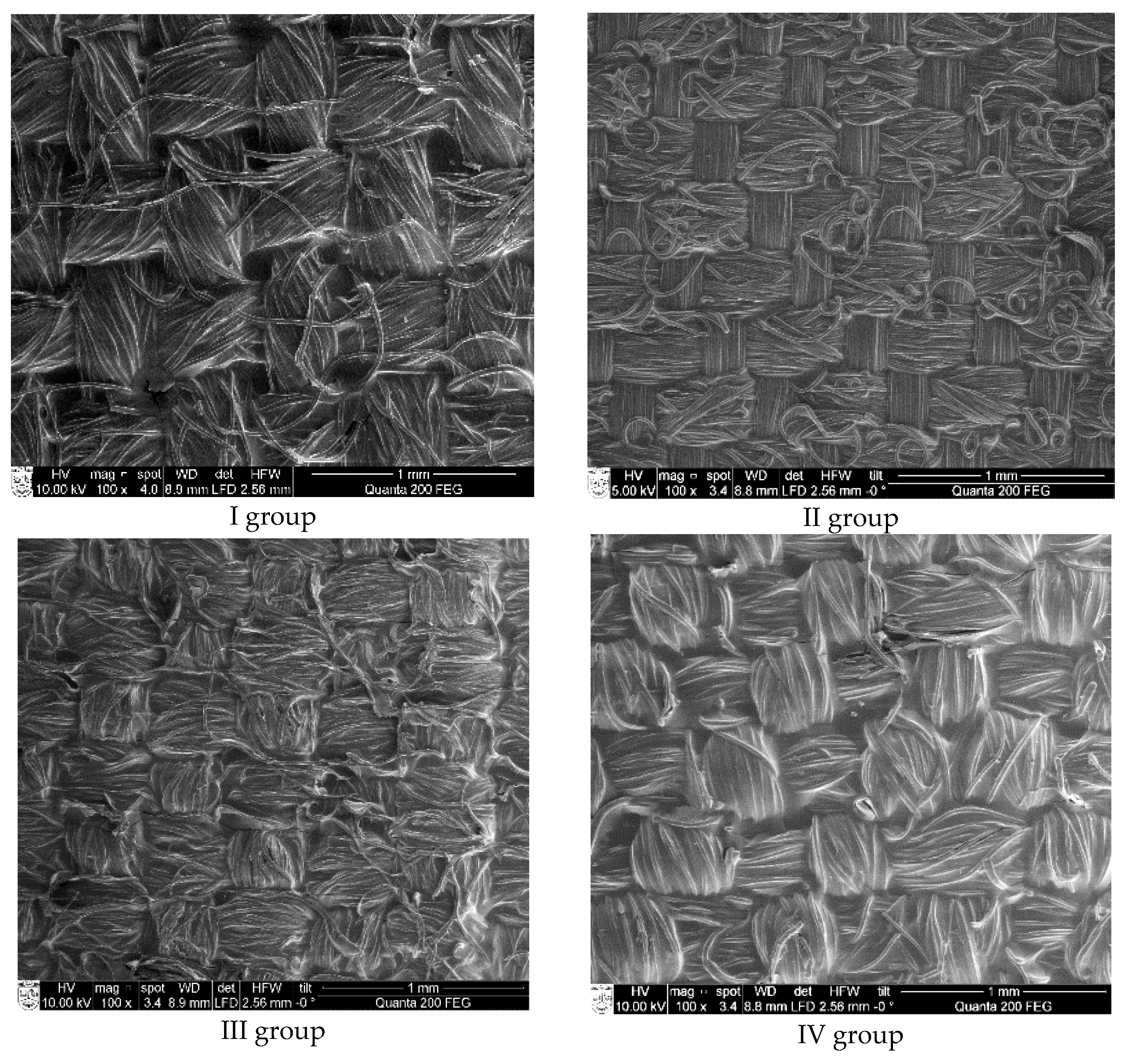
Structural parameters of substrate fabrics were determined using standard test methods, respectively: mass per unit area (g/m2) according to EN 12127 [37]; determination of the thickness of textiles (mm) according EN ISO 5084 [38], number of threads per unit length according to EN 1049-2 [39].
The amount of coating deposit (g/m2) for coated samples was evaluated by measuring mass per unit area of manufactured coated samples and subtracting the value of mass per unit area of control sample.

2.2.2. SEM Analysis

The surface morphology of the coated textile samples was examined applying scanning electron microscopy (SEM) and using a Quanta 200 FEG device (FEI, Eindhoven, Netherlands) at 20 keV (low vacuum). All microscopic images were made under the same technical and technological conditions: electron beam heating voltage—20.00 kV, beam spot—5.0, magnification—5000× and 10,000×, work distance—6.0 mm, low vacuum—80 Pa, and detector-LFD.

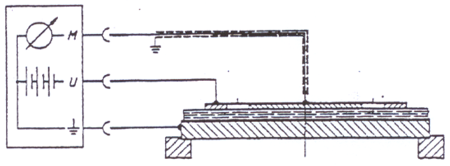
2.2.3. Electrical Conductivity

In order to evaluate the electrical conductivity of samples the reverse value—surface resistance was measured according to EN 1149-1 [40] standard, with Terra-Ohm-Meter 6206 (produced by Eltex-Electrostatik-GmbH, Weil am Rhein, Germany) applying voltage of 10 V. Five test specimens were cut to a size between the overall dimensions of the electrodes and of the base plate from the material designed. Specimens were pressed with the load of about 10 N between an assembly of cylindrical and annular electrode arranged concentrically with each other and base plate, on which the specimen was placed. The diameter of electrode used—100 mm. The range of the ohmmeter used 103 Ω to 1014 Ω. The conditioning for 24 h and tests were carried out in dry conditions—air temperature (23 ± 1) °C, relative humidity (25 ± 5) %, as indicated in the standard used. The measuring circuit of electrodes during measurements of resistance is presented in Figure 1.
The surface resistivity (ρ) was calculated according to equation:
ρ = k R ,
where R is the measured surface resistance, k is the geometrical factor of the electrode. The geometrical factor of the electrode is calculated according to equation:
k = 2 π log e ( r 2 r 1 ) = 2 3.14 log e ( 34.6 25.2 ) = 19.8 ,
where r 1 is the radius of the inner electrode and r 2 is the inner radius of the outer electrode.

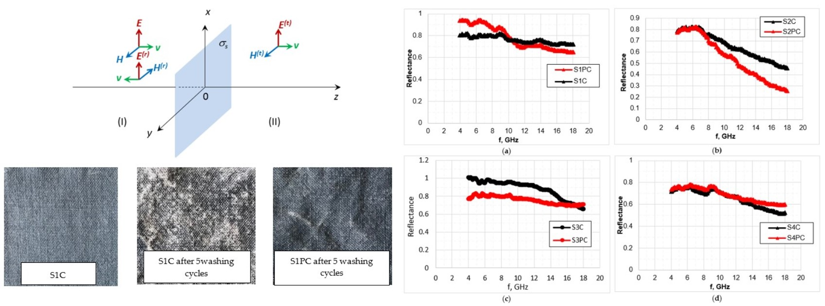
2.2.4. EMR Shielding, Reflection and Absorption

Experimental investigations of reflection and transmission of electromagnetic waves normally incident on fabrics have been performed in the far-field area, using a semi anechoic chamber. The measurement setup is shown in Figure 2.
It is seen that the measured sample of the fabric is surrounded with absorber sheets preventing for the diffracted wave directly get to the receiving antenna. We used tuneable microwave generator as a microwave source. Continuous wave signal was passed to the transmitting antenna. Transmitted and reflected power was measured using average power sensors from Rhode & Schwarz (Fleet, Hampshire, UK) NRP-Z24. The maximum absolute uncertainty for power measurements for such a sensor is 0.222 dB, which is equal to ±5.24 %. The receiving antenna measuring reflection was positioned near the transmitting one. Direct coupling between them was less than −30 dB. The measured transmitted power Pt with an object under the test was normalized by the power Pt0 measured in the absence of it. Therefore, the transmittance can be expressed in the following way:
T = P t P t 0
Results of transmittance are presented in a form of EMR shielding effectiveness SE expressed in decibels:
S E = 10 log 10 T
In order to calculate the microwave reflectance from the fabric under the test, the reflected microwave power from the fabric Pr is divided by the reflected power measured when the sample under the test is replaced with the same dimension metal plate Prm. Thus, the reflectance is calculated:
Γ = P r P r m
Absorption in a tested sample has been determined as a difference between falling, transmitted and reflected waves:
A = 1 T Γ
Three sets of horn antennas for measurements in a frequency range 2.4–4.0 GHz (S-band WR284), 4–7.5 GHz (C band WR159) and 7.5–18.0 GHz (X-band WR90) were used in our experiments. Rohde & Schwarz average power sensor was connected to the receiving antennas using corresponding waveguide to coaxial line adaptor. Using our measurement setup EMR Shielding effectiveness of the order of 35 dB can be measured. Combined standard uncertainty for shielding effectiveness and reflection measurements is equal to ±7.4 % for a single data point at a fixed frequency.

2.2.5. Calculation of the Surface Conductivity according to the Measurements of Reflectance and Transmittance

The fabrics covered with conductive paste can be considered as a thin layer with particular surface conductivity σs = 1/Rs, were Rs is surface resistance. Since the thickness of fabrics is much less than the wavelength of electromagnetic wave used in experiments, the dielectric properties of the fabric can be neglected. It also confirms our measurements of the substrate. We did not find any reflection or decrease of transmittance experimentally in the substrate fabric tests.
We consider a plane electromagnetic wave incident normally on a surface of the conductive textile characterized by the only parameter—surface conductivity. A schematic view of the situation is shown in Figure 3.
On the left side we have incident and reflected waves whereas on the right side we have transmitted wave only. The problem can be solved analytically applying boundary conditions at the interface z = 0. It is clear that the tangential component of electric field should be continuous in the interface of two regions, whereas the magnetic field component should have a step due to surface conductivity [41].
[ n × ( H ( 0 + ) H ( 0 ) ) ] = J s = σ s   E ( 0 )
where n is z axis directed unit vector perpendicular to the surface of the conductive layer, H (0) and H (0+) are tangential components of the magnetic field at the left and right sides from the layer, Js is a surface current density, and E (0) is the tangential component of the electric field in the layer (bolded letters in (7) correspond to vectors).
Assuming that the amplitude of electric field of the incident wave is continuous, the amplitudes of electric and magnetic field in the first region can be written in the following way
E ( z ) = e x [ 1 e i k z + E ( r ) e i k z ] ,
H ( z ) = e y [ 1 η e i k z E ( r ) η e i k z ] ,
where k = 2 π λ is a wavenumber and η is the impedance of free space. In the second region components of the electric and magnetic fields read:
E ( z ) = e x E ( t ) e i k z ,
H ( z ) = e y E ( t ) η e i k z .
The following boundary conditions should be satisfied at the interface
E ( I ) ( 0 ) = E ( I I ) ( 0 ) ,
H I ( 0 ) = H I I ( 0 ) + σ s E I I ( 0 ) .
Inserting there the expressions of amplitudes (8)–(11) one can get the system of two equations from which the reflection and transmission coefficients for amplitude can be obtained:
E ( r ) = η σ s 2 + η σ s ,
E ( t ) = 2 2 + η σ s .
As follows from the obtained expressions, reflection and transmission coefficients are real since the conductive sheet does not change a phase of reflected and transmitted waves. Reflectance and transmittance will be expressed as
Γ = [ η σ s 2 + η σ s ] 2 ,
T = 4 ( 2 + η σ s ) 2 .
Absorption in the layer can be easily calculated multiplying the drop of the amplitude of magnetic field with the amplitude of electric field in the layer leading to
A = 4 η σ s ( 2 + η σ s ) 2 .
It is easy to check that the sum of Γ, T and A equals to 1 that should follow from the energy conservation law. The obtained expressions (16), (17), and (18) can be used for the calculation of electromagnetic characteristics of the fabric samples covered with the conductive paste.

2.2.6. Evaluation of Conductive Coating Durability on Washing

Each fabric sample was subjecting to repeated 5 washing and drying cycles. The fabrics were washed in Scourotester Computex (Budapest, Hungary), using washing procedure described in EN ISO 105-C06 [42] standard, method A1S—washing temperature was 40 °C for 30 min with 150 mL of water containing 4 g/L of ECE Reference detergent with phosphates without optical brightener. Samples were then dried in ambient atmosphere.

2.2.7. Evaluation of Conductive Coating Durability on Abrasion

Interfacial bonding strength was assessed using Martindale abrasion measurements. Abrasion tests were performed using a Nu-Martindale Abrasion and Pilling Tester (James Heal, Halifax, UK), according to EN ISO 12947-2 [43]. Samples were treated with standard wool abradant applying 9 kPa pressure and the change in appearance after 50, 100, 200, and 1000 cycles was evaluated visually.

3. Results and Discussion

To develop the fabrics with EMR shielding and radar absorbing properties samples of woven fabrics were coated with the conductive paste—Clevios SV3 (Heraeus, Hanau, Germany), containing conjugated polymer system—poly(3,4-ethylenedioxythiophene)-polystyrene sulfonate (PEDOT:PSS). This paste was chosen not only for its merits mentioned in the introduction part, but also because of its suitability for screen printing or knife-over-roll coating technology, as our aim was to develop the fabric coated with conductive layer only on the back side, that it could be integrated in the military camouflage clothing system.
The substrate coated with conductive paste PEDOT:PSS and its yarn cross-section is illustrated in Figure 4. Analysis of SEM views of all coated substrates indicated that the thickness of the coating is not uniform and is approximately equal to 1 µm.
The most versatile form of PEDOT for processing is the synthesis of PEDOT as a polyelectrolyte complex [44]. The complex consists of polymeric cationic PEDOT and a polymeric counter anion [45]. The most effective counterion for PEDOT is polystyrenesulphonic acid (PSS) [8,19,45], which improves PEDOT solubility in water.
Researches assigned PEDOT:PSS to a “conducting acid dye” which can also tightly bind to protein fibres through electrostatic interaction of PSS chain negatively charged sulfonate (-SO3-) ions to protein fibre cationic sites [46]. The research of interaction between protein-based fibres and ICPs, PEDOT:PSS and poly(4-(2,3-dihydrothieno[3,4-b]-[1,4]dioxin-2-yl-methoxy)-1-butanesulfonic acid (PEDOT:S), at different pH was carried out in study [47]. The synthetic polyamide being the long chain polymers with recurring cationic amide (-CONH-) groups exhibited similar properties and can ionically bond as protein fibres [48]. Some trials to dye cotton yarns with PEDOT:PSS formulations were carried out by [49].
Therefore, for the investigated coated fabrics, the interaction between fibers and PEDOT:PSS happens likely due to electrostatic interaction among the water soluble conjugated polyelectrolyte PEDOT:PSS negatively charged sulfonate counterions with protonated amino groups in the wool and amide bonds in the polyamide as well as positively charged sites of chemically modified cotton.
However, the key obstacle for commercial application of conductive polymer coated fabrics is the poor adhesion of coating substance over the fiber surface [30,50]. To improve wear and washing resistance performance of fabrics coated with composition containing PEDOT:PSS, a conventional textile surface modification technique, atmospheric plasma treatment, was used.
As developed fabrics are intended for clothing protecting from EMR and against detection by battlefield radar, plasma treatment impact on their electrical and electromagnetic properties as well as on abrasion and washing resistance performance was studied.

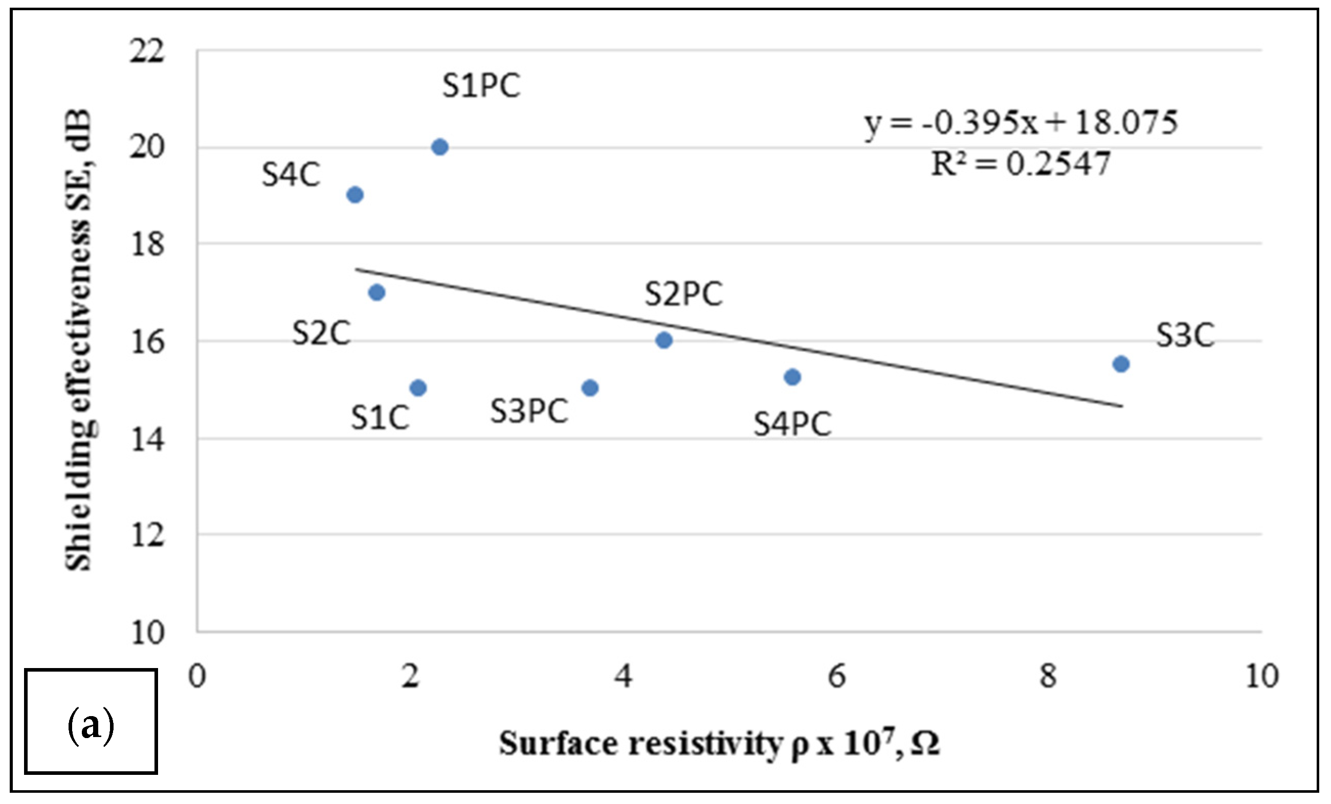
3.1. Electrical Conductivity

The electrical conductivity of the material is one of the important factors influencing its EMR shielding. Usually, in order to evaluate the electrical conductivity of the textile material, inverse dimension—surface resistivity is measured. For determination of this parameter there was used standard test method EN 1149-1 [40], which is mostly applicable for textile materials intended for protective clothing. The surface resistivity (ρ, Ω) measurement results presented in Table 4 show that before washing all tested materials are possessed of near the same electrical conductivity, despite they are treated with plasma or not. After washing procedures, the surface resistivity of samples slightly increased, ρ increased by one row, which means that the conductivity rather decreased. In this case also there was no marked differences between plasma treated and untreated samples, maybe except for samples from PA/cotton fibers (S3C and S3PC), where a positive plasma treatment influence can be noticed.
However, after analysis of the correlation between the surface resistivity of tested samples and EMR shielding effectiveness SE (dB) (Figure 5) was assessed, that knowledge of the surface resistivity, determined by the method used could not be used for the prediction of sample shielding ability. The coefficients of determination R2 = 0.2547 (Figure 5a) and R2 = 0.131 (Figure 5b) for the dependence of SE on the surface resistivity of samples before and after washing, respectively, shows that a correlation between these parameters is rather weak.
It stands to reason that results of ρ measurements, obtained for conductive paste coated samples with non-indiscrete surfaces (Figure 5), are not reliable and repeatable due to the method used, which does not exclude contact resistance in the system. The SEM images (Figure 6) illustrate that the surface of the coated side of fabric is not even and homogenous.
Therefore, obtained ρ values only show that applied conductive coating provides the fabrics with electrical properties, but does not allow objectively to distinguish the differences between samples and to predict their shielding ability.

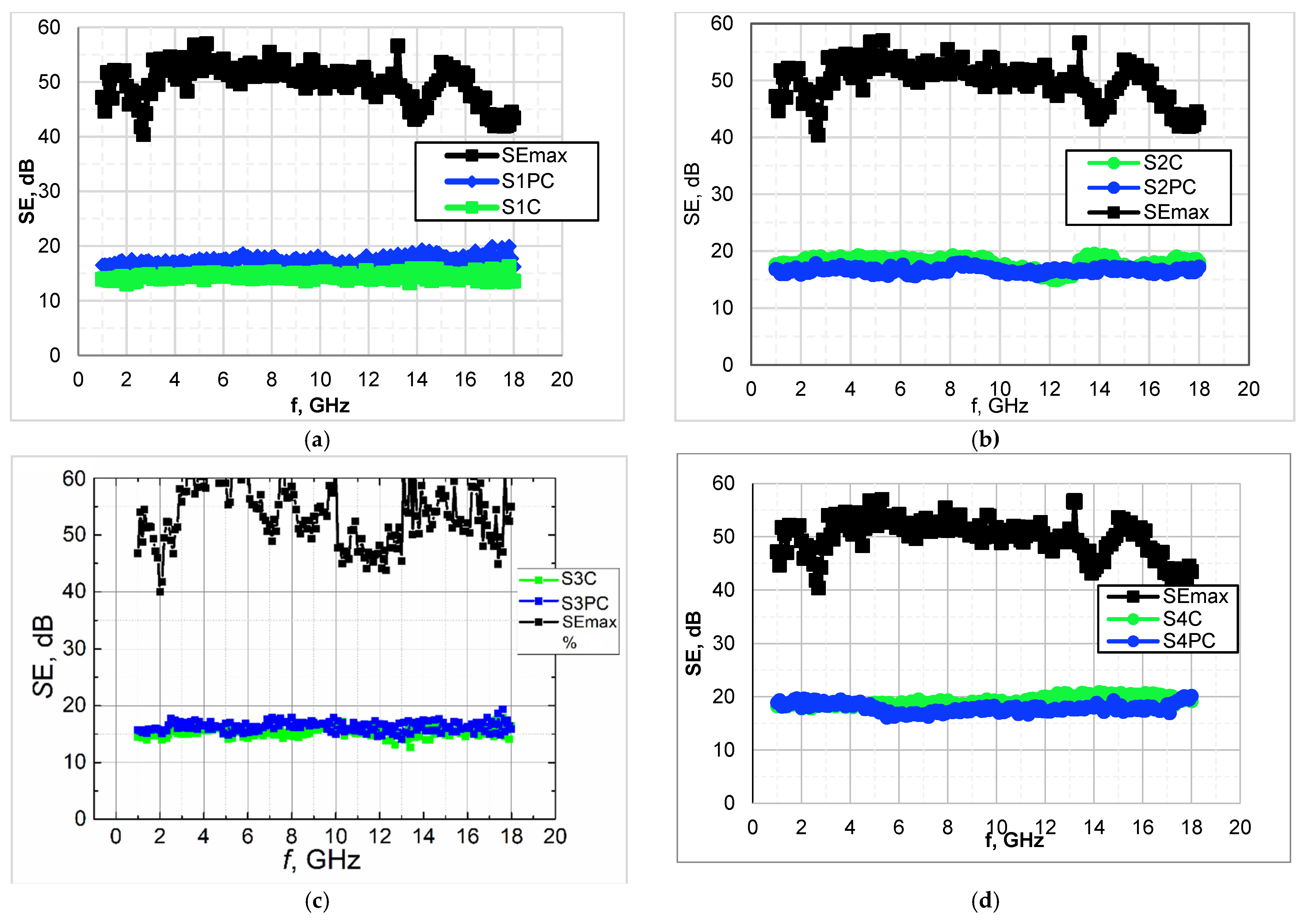
3.2. Microwave Properties

The main purpose to coat fabrics with conductive paste was to provide them with the function to shield EMR in microwave range likewise to absorb microwaves in radar operating range.
A major threat to dismounted soldiers are battlefield radars commonly operating within X and Ku-bands at 8–12 GHz and 12–18 GHz, respectively [51]. Consequently, the investigation of reflection and transmission properties of developed textile fabrics was performed in a frequency range of 2–18 GHz, which cover the defined frequencies relevant to the application. The experimental data show the variation in EMR shielding effectiveness for four groups of coated fabrics over the tested range (Table 5 and Figure 7). For the uncovered fabrics (substrate samples), EMR shielding effectiveness SE (dB) was 0.
All samples were coated with conductive paste (Table 3) in the equal conditions: the same screen, two layers (with intermediate drying) and thermo-fixation at 120 °C for 4 min. To shape the first layer, 4 passages were used and for the second, 2. However, the coating deposits were obtained different for each group of samples due to their particular structure (Table 1) and surface properties (wettability, moisture absorption and transport). With reference to obtained results, it could be stated that depending on such fabric structural parameters as—density, mass per unit area (or just mass), type of weave, as well as the apertures (pores), layer of shield (or coating) just sticks on the fabric surface or penetrates into fabric changing the shield thickness herewith turning SE results.
Individually, for each type of fabric, the coating deposit and herewith the amount of conductive additive, PEDOT:PSS, have the most important impact on shielding properties. In our previous works [23], as well as during preliminary experiments for this study, SE determined as a function of coating deposit. For example, substrate S3 with increasing coating deposit—7 g/m2, 14 g/m2, 17 g/m2, 24 g/m2, demonstrated increased |SE|—10 dB, 15 dB, 20 dB, 25 dB, respectively. Similar correlation between coating deposit and shielding effectiveness was obtained for other fabrics under this study. For further investigations the fabrics with sufficiently high SE, but not exceeding 20 dB were selected, as it was found [5] that for radar absorbing only materials with total EMR SE below 20 dB were suitable.
The data presented in Table 5 reports the average (dominant) SE values of coated fabrics with and without plasma treatment. As seen from results (Table 5 and Figure 7) EMR shielding ability for plasma treated samples in each group remain almost the same as for samples without plasma treatment, maybe with exception of wool samples (samples S1C and S1PC). In the case of the last-mentioned samples, SE values for plasma treated sample (SIPC) is slightly higher in comparison with untreated sample (S1C) due to a bit increase in coating deposit.
As can be seen from Figure 7, the shielding properties of coated samples are steady in all of the tested frequency range 2–18 GHz. Therefore, such a full side (in our case back side of the fabric) covered with conductive paste fabrics can be considered as a thin layer with particular surface conductivity.
The surface conductivity values calculated with reference to reflection and transmission measurements are presented in Table 5. It can be seen that calculated σ values strongly correlate with obtained SE values and allow to distinguish the samples with different conductivity, that is complicated using electrostatic parameter—surface resistivity, determined by the method conventional for textile testing.
To evaluate the ability of developed coated fabrics to absorb microwaves in radar operating frequency range, their reflection properties were measured (Figure 8) and absorption (A) coefficient calculated based on transmission and reflection measurements results (according to formulas (4) and (6)). The data presented in Table 6 show the contribution of reflection and absorption to the total EMR shielding effectiveness for each tested sample at 12 GHz and 18 GHz respectively.
As it is seen from Table 6, for tested samples the combined effect of reflection and absorption determines the shielding properties, but the role of these two parameters is different over the tested frequency range. As the reflection coefficient is more or less frequency depended for all tested samples (Figure 8), their reflectance properties are different over the 2–18 GHz range—reflectance decrease when the frequency increase. The lower reflection coefficients are obtained in the 12–18 GHz range, it means that in this range coated fabrics have the better absorption ability. Moreover, different types of fabric demonstrated different reflection and consequently absorption properties (Table 6).
The best results were obtained for group II samples (Figure 9)—the contribution of absorption at 18 GHz sought about 52% and 74% respectively for sample without plasma treatment (S2C) and with plasma treatment (S2PC). For other tested fabrics, no significant difference in reflection and absorption between plasma treated and untreated sample was noticed.

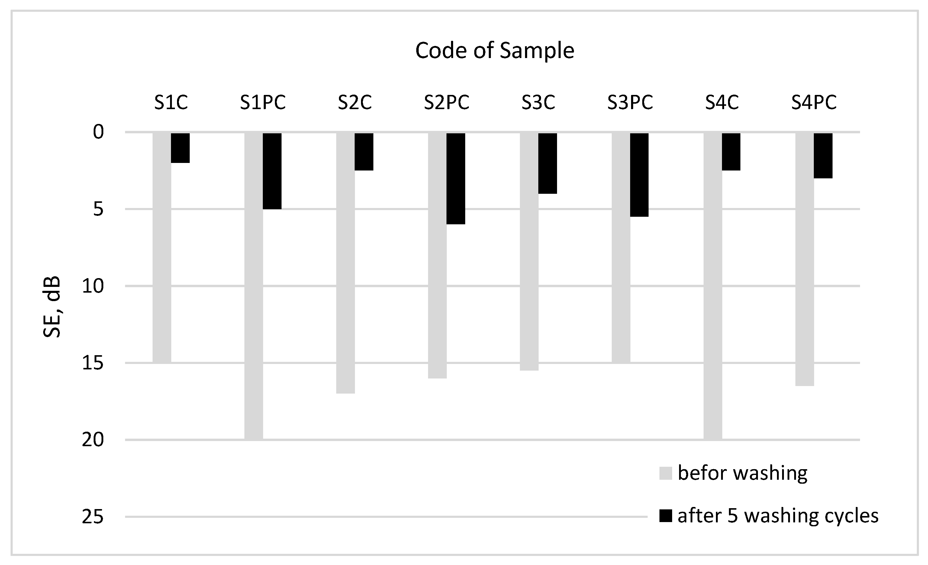
3.3. Washing and Wearing Resistance Performance

To assess washing resistance of coated fabrics all tested samples after washing procedures were measured not only for surface resistivity (Table 4), but also for shielding effectiveness. SE measurement results before and after washing (Figure 10) showed that, for all 4 groups of tested samples, the resistance to washing increased for samples with plasma treatment in comparison with untreated samples.
The samples after washing also were assessed visually. As an example, the photos of wool samples (I group) are presented in Figure 11.
Assessing the influence of washing on the durability of conductive coating, it could be stated that the plasma treatment slightly improved the durability of PEDOT:PSS coating.
The influence of plasma treatment on durability of coating was also observed after abrasion impact. As it can be seen from visual observations (Figure 12), the conductive coating survived after a longer period of abrasion cycles when samples were treated by plasma before coating procedure in comparison with untreated. These results clearly show that the plasma treatment was quite effective at improving the adhesion strength between textile substrate and the coating of a conductive composition containing PEDOT:PSS.
This change can be due to incorporation of additional functional groups formed by plasma reactions which changes the surface chemistry of textile substrate by decomposition of polymer chains and oxidation [50].

4. Conclusions

Different types of woven fabrics were coated using electrically conductive composition containing PEDOT:PSS. All samples developed for this study were characterized by surface resistivity and microwave properties within the 2–18 GHz frequency range. To improve the wear and washing resistance performance of the developed samples, conventional textile surface modification technique—atmospheric plasma treatment, was used.
Reflection and transmission measurements showed that for tested samples the combined effect of reflection and absorption determines the shielding properties, but the role of these two parameters is different over the tested frequency range. Shielding properties of investigated coated fabrics, with plasma treatment as well as without it, are steady in all tested frequency range and are sufficiently good for shielding/radar absorbing materials: SE for samples of groups I, II, and III is about 15–19 dB and for group IV 17–20 dB. There was no significant increase in SE due to plasma treatment, maybe except for samples of I group (wool fabric), where after the plasma treatment SE increased from 15 dB to 19 dB. This can be explained by the higher deposit of conductive paste on the fabric due to significant improvement in the hydrophilicity by plasma.
Meanwhile, reflection and consequently absorption are frequency-dependent. For all tested samples, the better absorption ability was obtained in the 12–18 GHz range. Moreover, it was noticed the positive effect of plasma treatment on absorption properties, particularly for samples of II (PA fabric) and III (PA/cotton) groups. The best results were obtained for II group’s samples (PA fabric): the contribution of absorption to shielding at 18 GHz was 52% for sample without plasma treatment and increased to 74% after plasma treatment.
It was found that EMR shielding effectiveness (SE) as well as absorption properties depend not only the amount of conductive paste topped on the fabric, but also resides in the construction parameters of fabrics and their finishing before coating. Depending on such fabric structural parameters as–density, mass per unit area, type of weave, layer of shield (or coating) just sticks on the fabric surface or penetrates into fabric changing the shield thickness herewith turning SE results. Meanwhile, the fiber composition of fabrics influences mostly bonding between fibers and polymer coating. The investigations have shown that applied plasma treatment visibly improved abrasion resistance as a result of better adhesion between textile substrate and coating. The most effectively plasma influenced abrasion resistance of wool (I group) and PA/cotton (III group) fabrics. SE measurement results before and after washing procedures showed that plasma treatment somewhat improved washing resistance of conductive coat. Comparing the shielding effectiveness of washed coated fabrics without and with plasma treatment, it was determined that for all tested fabrics with plasma treatment SE decreases less liken to untreated fabrics: for group I (wool fabrics) SE decreases 3.8 times for the plasma treated sample and 7.5 times for untreated and for other groups respectively, for group II (PA fabrics) 2.8 and 7.2 times; for group III (PA/cotton fabrics) 2.5 and four times; for group IV (aramid/viscose fabrics) 5.6 and eight times. However, washing resistance increased not so considerably as the binding strength of the coating was insufficient for such impact. A more significant improvement of resistance to washing of such coated fabrics will be the subject of our subsequent study.

Author Contributions

Conceptualization, A.A., V.R., and J.B.-G.; methodology, V.R., J.B.-G., and P.R.; investigation, V.R., J.B.-G., P.R., A.S., J.P., and G.S. writing—original draft preparation, V.R. and J.B.-G.; writing—review and editing, V.R. and J.B.-G.; supervision, A.A. All authors have read and agreed to the published version of the manuscript.

Funding

This research has been carried out within the Project Adaptive Camouflage for the Soldier II (ACAMSII) which has received funding from the European Union’s Preparatory Action for Defence Research—PADR programme under grant agreement No 800871.

Institutional Review Board Statement

Not applicable.

Informed Consent Statement

Not applicable.

Data Availability Statement

The data presented in this study are available on request from the corresponding author.

Conflicts of Interest

The authors declare no conflict of interest.

References

  1. International Agency for Research on Cancer (IARC). Radiation, Part 2: Non-Ionizing Radiofrequency Electromagnetic Fields, Monographs on the Evaluation of Carcinogenic Risks to Human; IARC: Lyon, France, 2013; Volume 102. [Google Scholar]
  2. Teber, A.; Unver, I.; Kavas, H.; Aktas, B.; Bansal, R. Knitted radar absorbing materials (RAM) based on nickel–cobalt magnetic materials. J. Magn. Magn. Mater. 2016, 406, 228–232. [Google Scholar] [CrossRef]
  3. Geetha, S.; Kumar, K.K.S.; Rao, C.R.K.; Vijayan, M.; Trivedi, D.C. EMI shielding: Methods and materials-A review. J. Appl. Polym. Sci. 2009, 112, 2073–2086. [Google Scholar] [CrossRef]
  4. Committee for Conformity Assessment on Accreditation and Certification of Functional and Technical Textiles. Specified Re-Quirements of Electromagnetic Shielding Textiles. 2010. Available online: http://www.ftts.org.tw/images/fa003E.pdf (accessed on 16 November 2016).
  5. King, J.A.; Pisani, W.A.; Klimek-McDonald, D.R.; Perger, W.F.; Odegard, G.M.; Turpeinen, D.G. Shielding effec-tiveness of carbon-filled polypropylene composites. J. Compos. Mater. 2016, 50, 2177–2189. [Google Scholar] [CrossRef]
  6. Brzeziński, S.; Rybicki, T.; Malinowska, G.; Karbownik, I.; Rybicki, E.; Szugajew, L. Effectiveness of shielding electro-magnetic radiation, and assumptions for designing the multi-layer structures of textile shielding materials. Fibres Text. East. Eur. 2009, 1, 60–65. [Google Scholar]
  7. Kim, S.H.; Jang, S.H.; Byun, S.W.; Lee, J.Y.; Joo, J.S.; Jeong, S.H.; Park, M.-J. Electrical properties and EMI shielding characteristics of polypyrrole-nylon 6 composite fabrics. J. Appl. Polym. Sci. 2003, 87, 1969–1974. [Google Scholar] [CrossRef]
  8. Onggar, T.; Kruppke, I.; Cherif, C. Techniques and Processes for the Realization of Electrically Conducting Textile Materials from Intrinsically Conducting Polymers and Their Application Potential. Polymers 2020, 12, 2867. [Google Scholar] [CrossRef]
  9. Tseghai, G.B.; Mengistie, D.A.; Malengier, B.; Fante, K.A.; Van Langenhove, L. PEDOT:PSS-Based Conductive Textiles and Their Applications. Sensors 2020, 20, 1881. [Google Scholar] [CrossRef] [PubMed] [Green Version]
  10. Avloni, J.; Ouyang, M.; Florio, L.; Henn, A.R.; Sparavigna, A.C. Shielding Effectiveness Evaluation of Metallized and Polypyrrole-coated Fabrics. J. Thermoplast. Compos. Mater. 2007, 20, 241–254. [Google Scholar] [CrossRef]
  11. Kaynak, A.; Håkansson, E. Characterization of conducting polymer coated fabrics at microwave frequencies. Int. J. Cloth. Sci. Technol. 2009, 21, 117–126. [Google Scholar] [CrossRef] [Green Version]
  12. Håkansson, E.; Amiet, A.; Kaynak, A. Dielectric characterization of conducting textiles using free space transmission measurements: Accuracy and methods for improvement. Synth. Met. 2007, 157, 1054–1063. [Google Scholar] [CrossRef] [Green Version]
  13. Onar, N.; Akşit, A.C.; Ebeoglugil, M.F.; Birlik, I.; Celik, E.; Ozdemir, I. Structural, electrical, and electromagnetic proper-ties of cotton fabrics coated with polyaniline and polypyrrole. J. Appl. Polym. Sci. 2009, 114, 2003–2010. [Google Scholar] [CrossRef]
  14. Joseph, N.; Varghese, J.; Sebastian, M.T. In situ polymerized polyaniline nanofiber-based functional cotton and nylon fabrics as millimeter-wave absorbers. Polym. J. 2017, 49, 391–399. [Google Scholar] [CrossRef]
  15. Engin, F.Z.; Usta, İ. Development and characterisation of polyaniline/polyamide (PANI/PA) fabrics for elec-tromagnetic shielding. J. Text. Inst. 2015, 106, 872–879. [Google Scholar] [CrossRef]
  16. Lee, C.Y.; Lee, D.E.; Jeong, C.K.; Hong, Y.K.; Shim, J.H.; Joo, J.; Kim, M.S.; Lee, J.Y.; Jeong, S.H.; Byun, S.W.; et al. Electromagnetic interference shielding by using conductive polypyrrole and metal compound coated on fabrics. Polym. Adv. Technol. 2002, 13, 577–583. [Google Scholar] [CrossRef]
  17. Marr, I.; Stöcker, T.; Moos, R. F3—Resistives Gasdosimeter auf Basis von PEDOT:PSS zur Detektion von NO und NO2. Tagungsband 2013, 317–320. [Google Scholar] [CrossRef]
  18. Ding, Y.; Invernale, M.A.; Sotzing, G.A. Conductivity Trends of PEDOT-PSS Impregnated Fabric and the Effect of Conductivity on Electrochromic Textile. ACS Appl. Mater. Interfaces 2010, 2, 1588–1593. [Google Scholar] [CrossRef] [PubMed]
  19. Otley, M.T.; Alamer, F.A.; Guo, Y.; Santana, J.; Eren, E.; Li, M.; Lombardi, J.; Sotzing, G.A. Phase Segregation of PEDOT:PSS on Textile to Produce Materials of >10 A mm−2Current Carrying Capacity. Macromol. Mater. Eng. 2017, 302, 1600348. [Google Scholar] [CrossRef]
  20. Liu, H.; Gong, Y.; Li, X.; Zhang, X.; Hu, C.; Wang, L.; Pang, Y.; Fang, C. The effect of in-situ polymerization on PE-DOT-PSS/PAN composite conductive fiber. In IOP Conference Series: Earth and Environmental Science 2019; IOP Publishing: Bristol, UK, 2019; Volume 218, p. 012161. [Google Scholar]
  21. Allison, L.; Hoxie, S.; Andrew, T.L. Towards seamlessly-integrated textile electronics: Methods to coat fabrics and fibers with conducting polymers for electronic applications. Chem. Commun. 2017, 53, 7182–7193. [Google Scholar] [CrossRef]
  22. Ding, Y.; Xu, W.; Wang, W.; Fong, H.; Zhu, Z. Scalable and facile preparation of highly stretchable electrospun PE-DOT: PSS@ PU fibrous nonwovens toward wearable conductive textile applications. ACS Appl. Mater. Interfaces 2017, 9, 30014–30023. [Google Scholar] [CrossRef]
  23. Rubežienė, V.; Abraitienė, A.; Baltušnikaitė-Guzaitienė, J.; Varnaitė-Žuravliova, S.; Sankauskaitė, A.; Kancleris, Ž.; Šlekas, G. The influence of distribution and deposit of conductive coating on shielding effectiveness of textiles. J. Text. Inst. 2018, 109, 358–367. [Google Scholar] [CrossRef]
  24. Guo, Y.; Otley, M.T.; Li, M.; Zhang, X.; Sinha, S.K.; Treich, G.M.; Sotzing, G.A. PEDOT: PSS “wires” printed on textile for wearable electronics. ACS Appl. Mater. Interfaces 2016, 8, 26998–27005. [Google Scholar] [CrossRef] [PubMed]
  25. Åkerfeldt, M.; Strååt, M.; Walkenström, P. Electrically conductive textile coating with a PEDOT-PSS dispersion and a polyurethane binder. Text. Res. J. 2012, 83, 618–627. [Google Scholar] [CrossRef]
  26. Kaynak, A. Conductive polymer coatings. In Active Coatings for Smart Textiles; Elsevier BV: Amsterdam, The Netherlands, 2016; pp. 113–136. [Google Scholar]
  27. Bonaldi, R.R.; Siores, E.; Shah, T. Characterization of electromagnetic shielding fabrics obtained from carbon nanotube composite coatings. Synth. Met. 2014, 187, 1–8. [Google Scholar] [CrossRef]
  28. Pakdel, E.; Wang, J.; Kashi, S.; Sun, L.; Wang, X. Advances in photocatalytic self-cleaning, superhydrophobic and electromagnetic interference shielding textile treatments. Adv. Colloid Interface Sci. 2020, 277, 102116. [Google Scholar] [CrossRef]
  29. Gashti, M.P.; Ghehi, S.T.; Arekhloo, S.V.; Mirsmaeeli, A.; Kiumarsi, A. Electromagnetic shielding response of UV-induced polypyrrole/silver coated wool. Fibers Polym. 2015, 16, 585–592. [Google Scholar] [CrossRef]
  30. Hegemann, D.; Brunner, H.; Oehr, C. Plasma treatment of polymers for surface and adhesion improvement. Nucl. Instrum. Methods Phys. Res. B 2003, 208, 281–286. [Google Scholar] [CrossRef]
  31. Cheng, J.; Zhao, B.; Zheng, S.; Yang, J.; Zhang, D.; Cao, M.-S. Enhanced microwave absorption performance of polyaniline-coated CNT hybrids by plasma-induced graft polymerization. Appl. Phys. A 2015, 119, 379–386. [Google Scholar] [CrossRef]
  32. Zhou, Y.; Sun, Z.; Jiang, L.; Chen, S.; Ma, J.; Zhou, F. Flexible and conductive meta-aramid fiber paper with high thermal and chemical stability for electromagnetic interference shielding. Appl. Surf. Sci. 2020, 533, 147431. [Google Scholar] [CrossRef]
  33. Su, M.; Gu, A.; Liang, G.; Yuan, L. The effect of oxygen-plasma treatment on Kevlar fibers and the properties of Kevlar fibers/bismaleimide composites. Appl. Surf. Sci. 2011, 257, 3158–3167. [Google Scholar] [CrossRef]
  34. Gordon, W.O.; Peterson, G.W.; Durke, E.M. Reduced Chemical Warfare Agent Sorption in Polyurethane-Painted Surfaces via Plasma-Enhanced Chemical Vapor Deposition of Perfluoroalkanes. ACS Appl. Mater. Interfaces 2015, 7, 6402–6405. [Google Scholar] [CrossRef]
  35. Dou, S.; Tao, L.; Wang, R.; El Hankari, S.; Chen, R.; Wang, S. Plasma-Assisted Synthesis and Surface Modification of Electrode Materials for Renewable Energy. Adv. Mater. 2018, 30, e1705850. [Google Scholar] [CrossRef]
  36. ISO 23232:2009. Textiles—Aqueous Liquid Repellency—Water/Alcohol Solution Resistance Test. Available online: https://www.iso.org/standard/50923.html (accessed on 15 January 2021).
  37. EN 12127:1997. Textiles. Fabrics. Determination of Mass Per Unit Area Using Small Samples. Available online: https://standards.cen.eu/dyn/www/f?p=204:110:0::::FSP_PROJECT,FSP_ORG_ID:11546,6229&cs=130ECEF2B5BBBAE89EF1B9A3396F60A81 (accessed on 15 January 2021).
  38. EN ISO 5084:1996. Textiles—Determination of Thickness of Textiles and Textile Products. Available online: https://standards.cen.eu/dyn/www/f?p=204:110:0::::FSP_PROJECT:11550&cs=197474BEE4A06921FE87D2AEAAECBE564 (accessed on 15 January 2021).
  39. EN 1049-2:1993. Textiles—Woven Fabrics—Construction—Methods of Analysis—Part 2: Determination of Number of Threads Per Unit Length. Available online: https://standards.cen.eu/dyn/www/f?p=204:110:0::::FSP_PROJECT:11547&cs=1BB22DB1B8E2F47A878DAE6CF64B44AAE (accessed on 15 January 2021).
  40. EN 1149-1:2006. Protective Clothing—Electrostatic Properties—Part 1: Test Method for Measurement of Surface Resistivity. Available online: https://standards.cen.eu/dyn/www/f?p=204:110:0::::FSP_PROJECT,FSP_ORG_ID:20552,6143&cs=1F5EFE9BBBA3F337AF53D236B7875229B (accessed on 15 January 2021).
  41. Orfanidis, S.J. Electromagnetic Waves and Antennas 2002; Rutgers University: New Brunswick, NJ, USA, 2002; pp. 227–250. [Google Scholar]
  42. EN ISO 105-C06:2010. Textiles—Tests for Colour Fastness—Part C06: Colour Fastness to Domestic and Commercial Laun-Dering (ISO 105-C06:2010). Available online: https://standards.cen.eu/dyn/www/f?p=204:110:0::::FSP_PROJECT,FSP_ORG_ID:31693,6229&cs=1925C0DDC367F5DAB74C85D67E6F4E802 (accessed on 15 January 2021).
  43. EN ISO 12947-2:2016. Textiles—Determination of the Abrasion Resistance of Fabrics by the Martindale Method—Part 2: Determination of Specimen Breakdown (ISO 12947-2:2016). Available online: https://standards.cen.eu/dyn/www/f?p=204:110:0::::FSP_PROJECT,FSP_ORG_ID:37839,6229&cs=19C8C568475C90DBE5D873E986AD4EF02 (accessed on 15 January 2021).
  44. Kirchmeyer, S.; Reuter, K. Scientific importance, properties and growing applications of poly(3,4-ethylenedioxythiophene). J. Mater. Chem. 2005, 15, 2077–2088. [Google Scholar] [CrossRef]
  45. Elschner, A.; Loevenich, W.; Eiling, A.; Bayley, J. ITO Alternative: Solution deposited Clevios TM PEDOT: PSS for transparent conductive applications. Heraeus Trade Artic. 2012. Available online: https://www.yumpu.com/en/document/read/10545247/english-cleviostm-conductive-transparent-and-flexible-polymers (accessed on 15 January 2021).
  46. Lund, A.; van der Velden, N.M.; Persson, N.-K.; Hamedi, M.M.; Müller, C. Electrically conducting fibres for e-textiles: An open playground for conjugated polymers and carbon nanomaterials. Mater. Sci. Eng. R Rep. 2018, 126, 1–29. [Google Scholar] [CrossRef]
  47. Khan, M.A. Dyeing of Wool and Silk Fibres with a Conductive Polyelectrolyte and Comparing Their Conductance. Master‘s Thesis, 2012. Available online: https://www.diva-portal.org/smash/get/diva2:1308230/FULLTEXT01.pdf (accessed on 15 January 2021).
  48. Moraes, M.R.; Alves, A.M.V.C.P.; Toptan, F.; Martins, M.S.; Vieira, E.M.F.; Paleo, A.J.; Souto, A.P.; Santos, W.L.F.; Esteves, M.D.F.; Zille, A. Glycerol/PEDOT:PSS coated woven fabric as a flexible heating element on textiles. J. Mater. Chem. C 2017, 5, 3807–3822. [Google Scholar] [CrossRef] [Green Version]
  49. Ryan, J.D.; Mengistie, D.A.; Gabrielsson, R.; Lund, A.; Müller, C. Machine-Washable PEDOT:PSS Dyed Silk Yarns for Electronic Textiles. ACS Appl. Mater. Interfaces 2017, 9, 9045–9050. [Google Scholar] [CrossRef] [PubMed]
  50. Deogaonkar, S.C. Dielectric barrier discharge plasma induced surface modification of polyester/cotton blend fabrics to improve polypyrrole coating adhesion and conductivity. J. Text. Inst. 2020, 111, 1530–1537. [Google Scholar] [CrossRef]
  51. Gupta, K.; Abbas, S.; Abhyankar, A. Carbon black/polyurethane nanocomposite-coated fabric for microwave attenuation in X & Ku-band (8–18 GHz) frequency range. J. Ind. Text. 2016, 46, 510–529. [Google Scholar] [CrossRef]
Figure 1. Measuring circuit of surface resistance measurement.
Polymers 13 01191 g001
Figure 2. Measurement setup of microwave transmission and reflection from the coated fabric. TA denotes transmitting and RA—receiving antennas.
Polymers 13 01191 g002
Figure 3. The model of fabric covered with conductive paste. On the left side of the sample there are incident and reflected waves. The later is denoted by superscript (r). On the right side the only transmitted wave appears. Its amplitudes are denoted by superscript (t).
Polymers 13 01191 g003
Figure 4. SEM image of S3C sample coated with PEDOT:PSS paste.
Polymers 13 01191 g004
Figure 5. Dependence of surface resistivity on shielding effectiveness: (a) unwashed samples; (b) samples after washing.
Polymers 13 01191 g005aPolymers 13 01191 g005b
Figure 6. SEM images of samples coated with conductive paste.
Polymers 13 01191 g006
Figure 7. Shielding effectiveness SE, dB of tested fabrics coated with PEDOT:PSS formulation: (a)—I group of samples; (b)—II group of samples; (c)—III group of samples; (d)—IV group of samples.
Polymers 13 01191 g007
Figure 8. Reflectance of tested fabrics coated with PEDOT:PSS formulation: (a)—I group of samples; (b)—II group of samples; (c)—III group of samples; (d)—IV group of samples.
Polymers 13 01191 g008
Figure 9. Absorption ability of tested samples: (a)—at 12 GHz frequency and (b)—at 18 GHz frequency.
Polymers 13 01191 g009
Figure 10. Influence of plasma treatment of shielding effectiveness before and after washing procedure.
Polymers 13 01191 g010
Figure 11. An appearance of coated side of fabric after washing procedures.
Polymers 13 01191 g011
Figure 12. Coated fabric samples after being subjected to abrasion in the Martindale abrasion tester.
Polymers 13 01191 g012
Table 1. The description of fabrics developed for the investigation.
Group of Samples (and Substrate View, Magnified ×60)Code of FabricDescriptionMean Mass Per Unit Area *, g/m2Thickness, mmNumber of Threads Per Unit Length
No. of Warp Threads Per 1 cmNo. of Weft Threads Per 1 cm
I Polymers 13 01191 i001S1Substrate (1)—100 % wool woven fabric (without plasma treatment and without conductive coating)1270.492218
S1CSubstrate (1) coated with conductive paste
S1PCSubstrate (1) treated with plasma and coated with conductive paste
II Polymers 13 01191 i002S2Substrate (2)—100 % polyamide woven fabric, printed with camouflage pattern (without plasma treatment and without conductive coating)1300.454732
S2CSubstrate (2) coated with conductive paste
S2PCSubstrate (2) treated with plasma and coated with conductive paste
III Polymers 13 01191 i003S3Substrate (3)—58 % cotton/42% polyamide woven fabric (without plasma treatment and without conductive coating)2270.672825
S3CSubstrate (3) coated with conductive paste
S3PCSubstrate (3) treated with plasma and coated with conductive paste
IV Polymers 13 01191 i004S4Substrate (4)—Aramid/viscose 55%/45% woven fabric, printed with camouflage pattern (without plasma treatment and without conductive coating)2360.673824
S4CSubstrate (4) coated with conductive paste
S4PCSubstrate (4) treated with plasma and coated with conductive paste
*—The evaluated expanded uncertainties (U) for measurement of mean mass per unit area is ±5 g/m2. The reported expanded uncertainties are based on a standard uncertainty multiplied by a coverage factor k = 2, which for a normal distribution provides a level of confidence of approximately 95%.
Table 2. Level of aqueous liquid repellence test for the untreated and treated fabrics with corona, after one and two passages.
Code of FabricNo TreatmentTreatment
(1 Passage)
Treatment
(2 Passages)
S1Level 3Level 1Level 1
S2Level 0Level 0Level 0
S3Level 3Level 1Level 0
S4Level 0Level 0Level 0
Table 3. Properties of conductive paste applied (product supplier information)
Properties
Composition/information on ingredients (component name and % by weight)Propylene glycol ≤ 66.5
2,2′-oxydiethanol ≤ 15
Benzensulphonic Acid, Ethenyl-, Homopolymer, Compd.with
2,3-dihydrothienol[3,4-b]-1,4-dioxin Homopolymer ≤ 15
Surface resistivity
(test print)
700 Ω/sq
Product description (supplied form)Aqueous dispersion
Table 4. The electrostatic properties of investigated fabrics.
Group of Samples Code of SampleSurface Resistivity *
ρ, Ω
Surface Resistivity *After Washing
ρ, Ω
IS1C2.1 × 1071.7 × 108
S1PC2.3 × 1072.6 × 108
IIS2C1.7 × 1074.3 × 108
S2PC4.4 × 1073.3 × 108
IIIS3C8.7 × 1072.1 × 108
S3PC3.7 × 1074.5 × 108
IVS4C1.5 × 1071.0 × 108
S4PC5.6 × 1073.7 × 108
* The evaluated expanded uncertainty (U) for surface resistivity (ρ) measurement U = ρ·0.12 [Ω]; The reported expanded uncertainties are based on a standard uncertainty multiplied by a coverage factor k = 2, which for a normal distribution provides a level of confidence of approximately 95%.
Table 5. EMR shielding effectiveness of investigated fabrics.
Group of SamplesCode of SampleDominant Shielding Effectiveness
SE, dB
(2–18 GHz)
Deposit of Conductive Paste, g/m2Surface
Conductivity, S
IS1C15102.5 × 10−2
S1PC18–19124.0 × 10−2
IIS2C16–1853.5 × 10−2
S2PC15–1753.2 × 10−2
IIIS3C15–16142.5 × 10−2
S3PC15152.5 × 10−2
IVS4C18–2064.7 × 10−2
S4PC17–2074.7 × 10−2
Table 6. Microwave properties of tested coated fabrics.
Group of SamplesCode of SampleFrequency
12 GHz18 GHz
Components of Shielding Effectiveness %
ΓATΓAT
IS1C75.021.83.270.026.83.2
S1PC75.024.01.055.044.01.0
IIS2C60.037.52.545.052.52.5
S2PC50.046.83.225.074.82.0
IIIS3C90.06.83.270.026.83.2
S3PC75.021.83.270.026.83.2
IVS4C65.034.01.050.048.41.6
S4PC65.033.02.060.039.00.1
Publisher’s Note: MDPI stays neutral with regard to jurisdictional claims in published maps and institutional affiliations.

