Article

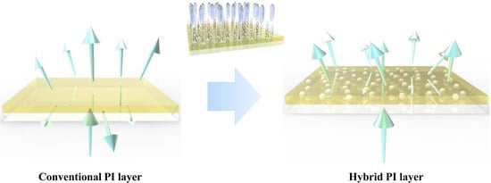
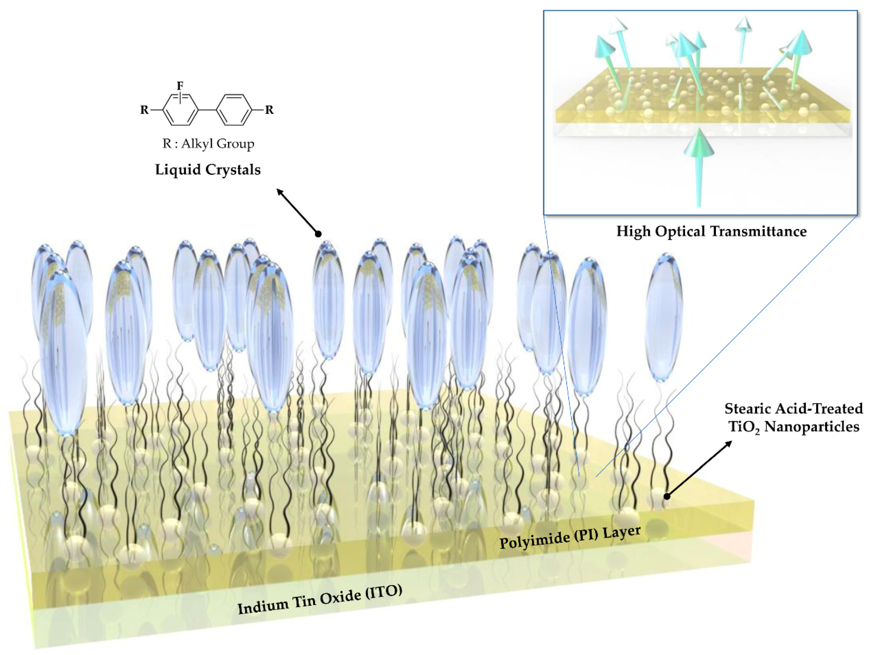
Fabrication of TiO2-Embedded Polyimide Layer with High Transmittance and Improved Reliability for Liquid Crystal Displays

Department of Chemical Engineering, Soongsil University, Seoul 06978, Korea
*
Author to whom correspondence should be addressed.
Polymers 2021, 13(3), 376; https://doi.org/10.3390/polym13030376
Submission received: 31 December 2020 / Revised: 22 January 2021 / Accepted: 23 January 2021 / Published: 26 January 2021
(This article belongs to the Special Issue Metal Nanoparticles–Polymers Hybrid Materials II)

Abstract

:
Construction of liquid crystal (LC) alignment by introducing polyimide (PI) to indium tin oxide (ITO) electrodes is one of the main methods to realize high-resolution images in liquid crystal displays (LCD). However, the loss of transmittance caused by the difference in refractive index between ITO and PI leads to direct degradation of LCD performance. Thus, we herein fabricated a functional hybrid PI alignment layer that reduces the difference in refractive index and greatly increases the transmittance of the device by introducing inorganic titanium dioxide (TiO2) nanoparticles (NP) to the organic PI. The highly refractive TiO2 NPs were surface-treated with stearic acid comprising long alkyl chains to improve their dispersibility and uniformly dispersed in the PI matrix by simply stirring the mixture. The hybrid PI mixture was spin-coated on the ITO substrate, and the resulting LC cell exhibited excellent electro-optical properties. In addition, the reliability of the LC cells was enhanced by the inclusion of the TiO2 NPs, which was confirmed through the evaluation of voltage holding ratio, residual direct current, and LC cell reliability. Overall, functional hybrid PI can be used in advanced display technology for next-generation LC devices that require high transmittance and reliability.

Graphical Abstract

1. Introduction

Currently, the liquid crystal display (LCD) is widely used in various applications such as smartphones, monitors, cameras, and other devices [1,2,3]. In order to drive the device, the liquid crystal (LC) molecules must be controlled by the applied voltage [4,5]. In addition, a vertically aligned LC device with good display performance can only be implemented when the initial orientation of the LCs is uniformly aligned. One of the most important electro-optical properties of a LC-based display device is transmittance. For this reason, indium tin oxide (ITO), a transparent electrode, is used as the electrode of the display. The ITO electrode is used not only in LCDs but also in many displays such as organic light emitting diodes (OLED) and quantum dot light emitting diodes (QLED) [6,7,8,9]. In addition, the alignment layer that determines the initial orientation of the LC is also important, and the most commonly used material for this layer is polyimide (PI) [10,11,12,13,14,15,16]. The LC can be uniformly aligned along a desired direction through the interactions of the LC molecules at the molecular level. However, the commonly used PI lowers the optical transmittance of the device due to a mismatch in its refractive index with that of the ITO substrate. In addition to the problem of the lowered transmittance, the electro-optical properties of the device may be lowered due to the free ions generated by impurities during the synthesis of the LC [17,18]. These free ions move between the electrodes and induce a screening effect, thereby degrading the performance of the device [19].
Therefore, we herein propose a facile and effective method to capture the free ions in LCs to suppress the screening effect while simultaneously increasing the transmittance of the device. Introducing stearic acid-treated TiO2 nanoparticles (NPs) into the PI polymer can solve the problems presented above (Figure 1). The long hydrophobic alkyl chains in the stearic acid improve the vertical alignment capability of the LC, which in turn improves the controllability of the LC by the applied voltage. In addition, TiO2 has a high refractive index of 2.6, and thus the optical transmittance of the device can be increased by the closely matched refractive index of the PI layer (1.6) with that of the ITO substrate (1.8). Moreover, the screening effect can be prevented because of the ability of the TiO2 NPs to trap the free ions of the LC [20,21,22]. The effects of the TiO2 NPs introduced into PI were evaluated by using two sizes of NPs (15 and 300 nm) and different NP contents. The functional hybrid PI layer was found to improve not only the optical performance but also the reliability of the manufactured LC device. As mentioned earlier, LC-based devices used in televisions and monitors must achieve the same performance even under long-term operation. A problem of existing LCDs is the phenomenon of an image sticking from long-term operation [23,24,25,26,27]. In addition to suppressing the screening effect and preventing the generation of a residual direct current (DC) voltage, the introduced TiO2 NPs also maintained the vertical alignment ability of hybrid PI layer due to the effects of the long hydrophobic alkyl chains of stearic acid. Improved electro-optical properties of the device can be obtained by a simple mixing process, and thus the proposed method can be implemented easily to produce a competitive alignment layer in displays requiring high transmittance and reliability.

2. Materials and Methods

2.1. Preparation of Functional Hybrid Polyimide Layer

Various levels of surface-treated inorganic TiO2 NPs (Cosmax, Seongnam, Korea) were added to the organic PI in N-methyl-2-pyrrolidone (AL607XX, JSR, Tokyo, Japan) and then stirred for 24 h at 25 °C. The sizes of the surface-treated TiO2 NPs were 15 and 300 nm and the mass ratios of NPs to PI solution were 0.01, 0.05, 0.1, and 0.5 wt%. The NPs were well dispersed in the PI solution due to the organic alkyl chains of stearic acid. The prepared PI mixtures of each ratio were coated on the ITO substrates and then thermally cured at 200 °C for 1 h. Thus, the functional hybrid PI alignment layer with a thickness of approximately 100 nm was prepared [28,29].

2.2. Fabrication of the LC Cell Containing the Functional Hybrid Polyimide Alignment Layer

Prior to introducing the ITO substrate (0.02 kΩ/cm2, 0.7 mm, Fine Chemical Industry, Seoul, Korea) as an electrode of the LC cell, the following cleaning process was performed. The substrate was sequentially washed with acetone (97%, Junsei Chemicals, Tokyo, Japan), isopropyl alcohol (98%, Daejung Chemicals, Siheung, Korea), and de-ionized (DI) water for 10 min under ultrasonication and then dried for 15 min on a hot plate at 100 °C. The cleaned substrates were used as the upper and lower electrodes of the cell. Then, the mixtures containing 0.01, 0.05, or 0.1 wt% of TiO2 NPs were uniformly spin-coated onto the ITO electrodes to act as the LC alignment layer. The homogeneous hybrid PI layer was prebaked at 80 °C and then imidized at 200 °C for 1 h. To maintain the LC cell gap at 5.25 μm, a spacer (SP-205XX, Sekisui Chemical, Tokyo, Japan) was used, and the upper and lower substrates were sealed using UV curable sealant (SP-25XX, Sekisui Chemical, Tokyo, Japan). The applied sealant was cured by UV irradiation at an energy of 3 J/cm2. After the sealant curing process, the nematic LCs comprising fluorobiphenyl derivatives (TNI = 75 °C, ∆n = 0.095, ∆ε = −3.1, Merck, Darmstadt, Germany) was injected into the LC cell by capillary force and annealed at 100 °C for 1 h.

2.3. Characterization

Polarized optical microscopy (POM; BX51, Olympus, Tokyo, Japan) was performed to investigate the alignment properties of the LCs. Contact angle measurements (Phoenix MT-A, SEO, Suwon, Korea) were carried out to examine the effect of the surface-treated TiO2 NPs on the hydrophobic properties of hybrid PI layer. Atomic force microscopy (AFM) was conducted in contact mode with silicon tips using a PSIA XE-100 (Park systems, Suwon, Korea). To examine the optical transmittance of the LC cell, ultraviolet-visible spectroscopy (UV–vis; Mega-900, Scinco, Seoul, Korea) was performed. To confirm the electro-optical performance of the manufactured LC cells, the voltage-transmittance (V-T) curves and response times were recorded using an electro-optical measurement system comprising a laser light source (1135P, JDSU, Milpitas, CA, USA), a photodetector (ET-2000, EOT, Edinburgh, UK), a function generator (33210A, Agilent, Santa Clara, CA, USA), and an oscilloscope (TBS1062, Tektronix, Beaverton, OR, USA). The test LC cell was aligned between the laser light source and the photodetector with crossed polarizers, and then the electro-optical measurement was carried out using a function generator (LC cell) and an oscilloscope (photodetector) (Figure 2). The voltage holding ratio (VHR) and residual direct current (RDC) of the LC cell were evaluated using an LC characteristic measurement system (Model 6254, Toyo, Tokyo, Japan).

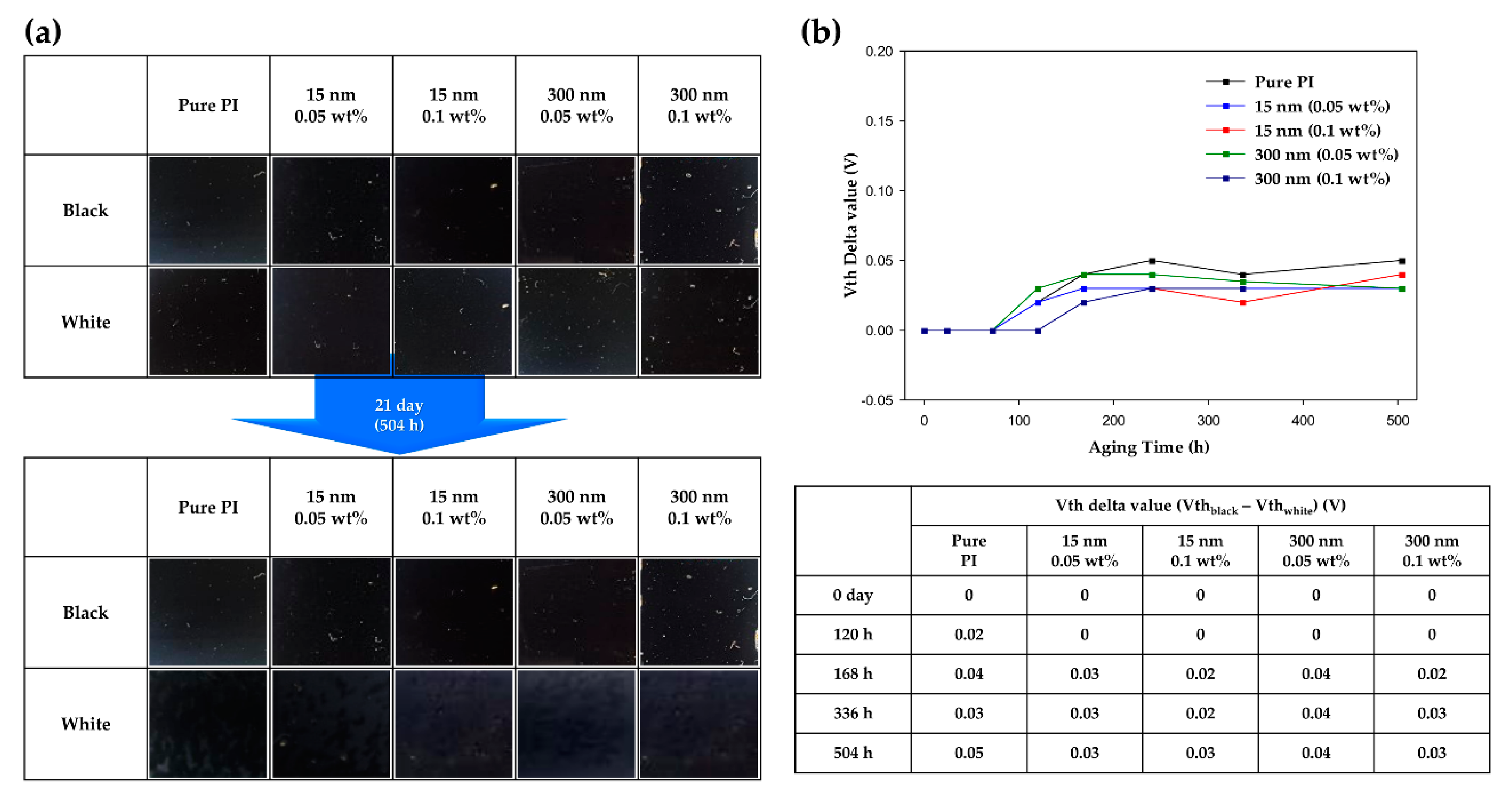
3. Results and Discussion

To determine the effect of the surface-treated TiO2 nanoparticles on the hydrophobicity of functional hybrid PI layer, contact angle measurements were performed. Figure 3a shows the water contact angles for each content of TiO2 NPs of 15 and 300 nm in size. The contact angles of the functional hybrid PI layer were 71.4, 72.6, 76.6, and 83.2° at 0.01, 0.05, 0.1, and 0.5 wt%, respectively, for 15-nm-TiO2. Additionally, the contact angles of the hybrid PI layer containing 0.05 and 0.1 wt% 300-nm-TiO2 were 73.5 and 76.2°, respectively. Notably, the water contact angles of the hybrid PI layers were higher than that of pure PI layer (70°). From these results, it was confirmed that the water contact angle of the hybrid PI layer increased as the TiO2 NP content increased. These results are attributed to the influence of the long hydrophobic alkyl chains of stearic acid on the TiO2 surface. As the content of surface-pretreated TiO2 increases, the hybrid PI layer coated on the ITO substrate becomes more hydrophobic and the contact angle of DI water, which is the test sample, increases. As a result, it was confirmed that the surface of TiO2 was treated with stearic acid, and the change in the surface energy of each substrate was confirmed. In addition, Figure 3a shows the trend of the contact angle due to the two sizes of TiO2 NPs, where the influence of stearic acid was once again confirmed. As mentioned above, as the TiO2 content increased, the contact angle also increased, and this trend was the same for both TiO2 dimensions (15 and 300 nm). Furthermore, when the TiO2 content was the same, the contact angles were similar even if the size of the TiO2 NPs was different, confirming that the alkyl chains of stearic acid, not the size of the TiO2 particles, dominantly affected the change in the surface energy. Importantly, the long alkyl chains of stearic acid attached to the NP surface interacted with the LC molecules to induce vertical alignment of the LC molecules.
AFM and solubility measurements were performed to confirm the dispersibility of the TiO2 NPs in the PI layer. From the photographic images of the hybrid PI solutions, it is confirmed that the TiO2 NPs are well dispersed in the PI solution without precipitation of particles, as shown in Figure 3b. Moreover, the three-dimensional view images of AFM show that 15-nm-TiO2, which is smaller than PI layer, has a uniform surface morphology without particle aggregations, and the surface roughness increases as the TiO2 content increases, indicating the uniform dispersion of the TiO2 in the PI layer. In case of 300-nm-TiO2, since the size of TiO2 is larger than thickness of PI layer (100 nm), the protrusions of TiO2 NPs were found, but their sizes were similar to that of TiO2 particle. Furthermore, as the content increased, the number of protrusions increased in a uniform manner. These results suggest that the surface-pretreated TiO2 NPs can afford high dispersibility in the PI layer.
POM images of the LC cells with pure PI and hybrid PI alignment layers were obtained to confirm the vertical alignment ability of the LCs due to the introduction of the improved alignment layer. Pure PI, which is conventionally used as the LCD alignment layer, shows a clear image with parallel and cross polarizers. In other words, the pure PI alignment layer vertically aligned the initial direction of the LCs. As shown in Figure 4a, the LC cells containing the hybrid PI layer (prepared using the 15-nm-TiO2 NPs) also provided clear images. The clarity of the hybrid PI-LC cells under polarization is comparable to that of pure PI-LC cell. From this result, it was confirmed that the new hybrid PI alignment layer does not adversely affect the vertical alignment of the LCs. In addition, as mentioned above, the long alkyl chains of stearic acid on the surface of the TiO2 NPs facilitate vertical alignment through their interactions with the LCs. Figure 4b shows the voltage-transmittance (V-T) curves measured to confirm the electro-optical characteristics of the manufactured LC cells. To compare with pure PI, hybrid PI-LC cells were also tested under the same conditions. The threshold voltage value of the pure PI-LC cell was 2.22 V, and those of the hybrid PI-LC cells were 2.24, 2.27, 2.38, and 2.42 V for TiO2 contents of 0.01, 0.05, 0.1, and 0.5 wt%, respectively. Here, the threshold voltage is defined as the voltage at 10% transmittance of the LC cell [30,31]. Evidently, the threshold voltage values of the hybrid PI-LC cells were higher than that of the pure PI-LC cell. The reason for the increase in the threshold voltage from that of the pure PI-LC cell is that the alkyl chains of stearic acid contained in the hybrid PI layer interact with the LCs to further increase the vertical alignment of the LCs. The decay time of each cell was measured to determine the response speed, as shown in Figure 4c. The gray-to-gray method, which is most commonly used, was used to measure the response speed. Here, the gray range was designated as dark gray and light gray for a transmittance of 10 and 90%, respectively [32,33,34]. Therefore, the decay time is the time taken to drop from 90 to 10% of the transmittance. The decay time of the pure PI-LC cell was 15 ms, and those of the hybrid PI-LC cells were 15, 11, 10, and 7 ms for TiO2 contents of 0.01, 0.05, 0.1, and 0.5 wt%, respectively. It can be seen that the decay time in the hybrid PI-LC cells were faster than that of the pure PI-LC cell, and the higher the TiO2 content, the faster the decay time. As a result, it was once again confirmed that the vertical alignment ability of the LC was improved by hybrid PI layer with the surface-treated TiO2 NPs.
To determine the electro-optical characteristics of the cells according to the size of the TiO2 NPs, measurements were performed using the same abovementioned method. The size of the TiO2 particles increased from 15 nm to 300 nm, and the surface of the TiO2 NPs was treated with stearic acid in the same way as the 15-nm-TiO2. In addition, two hybrid PIs with TiO2 contents of 0.05 and 0.1 wt% were prepared. As shown in Figure 5a, the POM image of the hybrid PI-LC cell with the 300-nm-TiO2 is comparable to that of the pure PI-LC cell; clear images were obtained under parallel and crossed polarizations without light leakage. Similar to the results for 15-nm-TiO2, 300-nm-TiO2 induced a stable vertical alignment of the LCs, and both cells with different TiO2 contents showed similar performances. Figure 5b shows the V-T curves of a hybrid PI-LC cell containing 300-nm-TiO2. The threshold voltage values of 2.25 and 2.28 V were obtained at TiO2 contents of 0.05 and 0.1 wt%, respectively; these values were similar to that of the pure PI-LC cell, but they were slightly lower than those of the hybrid PI-LC cells containing 15-nm-TiO2. Specifically, when comparing the threshold voltage values of the two types of cells containing 0.1 wt% of 15-nm-TiO2 and 300-nm-TiO2, the hybrid PI-LC cell containing 15-nm-TiO2 showed a higher value (+ 0.1 V). Although this difference is insignificant, it can be seen as an effect of the particle size because different voltages were obtained at the same TiO2 content. Because the size of the particles increases by 20 times (from 15-nm-TiO2 to 300-nm-TiO2), the amount of 300-nm-TiO2 doped in PI is lower compared with the 15-nm-TiO2 doped PI, leading to the decrease in vertical alignment ability of the hybrid PI layer. This particle size effect can be seen in detail in the response speed results shown in Figure 5c. The response speed of the prepared cells was 12 and 19 ms at 0.05 and 0.1 wt%, respectively. The decay time of the cell with 0.1 wt% TiO2 NPs was approximately two times higher than that of 15-nm-TiO2 at 0.1 wt%. This difference, as mentioned above, can be considered due to the particle size effect in which the applied amount of TiO2 particles decreases as the size increases. As a result, the particle size effect (15 and 300 nm) was confirmed, and the electro-optical properties of the LC cells containing 300-nm-TiO2 were also confirmed to be similar to that of the pure PI-LC cell.
To confirm the improved optical transmittance due to TiO2 doping, UV–vis spectra were acquired. As can be seen in Figure 6, the increase in transmittance from an LC cell composed of pure PI to the LC cells composed of hybrid PI layers containing TiO2 was confirmed. A saturation voltage was applied to the prepared cells to create a white state, and after attaching a polarizing film to the upper and lower substrates of the cells, the transmittance was measured based on air. The transmittance of the pure PI-LC cell at a wavelength of 550 nm was 14.54%. In the same wavelength band, the transmittance values of the hybrid PI-LC cells containing TiO2 contents of 0.05 and 0.1 wt% were, respectively, 15.50 and 15.29 for 15-nm-TiO2 and 16.87 and 17.61 for 300-nm-TiO2. The transmittance of the LC cells containing the hybrid PI alignment layer was higher than that of the pure PI-LC cell. In particular, in the case of the hybrid PI-LC cell containing 0.1 wt% of 300-nm-TiO2, an increase from the reference value of the pure PI-LC cell by 20% was observed. The reason for this result is that the hybrid PI alignment layer performs better than the pure PI layer in LC control according to the applied voltage. The long hydrophobic alkyl chains of stearic acid treated on the TiO2 NP surface interact with the LCs, and thus LC control is easier. As mentioned earlier, the hybrid PI can suppress the screening effect due to the ion trapping effect of TiO2. On the other hand, pure PI without TiO2 has a lower optical transmittance than the hybrid PI because the LC receives a relatively lower voltage in the cell than the applied voltage due to the screening effect. In addition, the high refractive index of TiO2 can be suggested as an additional reason for the increase in the optical transmittance of the LC cell. Since the conventional pure PI layer has a lower refractive index than the ITO substrate, a loss in light transmittance can be generated due to the total reflection, but the refractive index between the two layers is closely matched due to doping with TiO2, which has a high refractive index, thereby increasing the optical transmittance. For these reasons, it was confirmed that the optical transmittance of LC cell was improved by introducing TiO2 NPs into PI layer, and the transmittance increased as the size of the TiO2 NPs increased.
The measurements for voltage holding ratio (VHR) and residual direct current (RDC) were carried out to confirm the reliability performance of the LC cells for long-term operation. The VHR is a function of an LCD device that maintains the applied voltage. A low VHR leads to device performance drawbacks, such as image sticking. Figure 7a shows the VHR curves of the LC cells fabricated with pure PI and hybrid PI layers. The VHR values of the cells containing TiO2 contents of 0.05 and 0.1 wt% were, respectively, 97.04 and 94.06% for 15-nm-TiO2, and 96.01 and 95.32% for 300-nm-TiO2. Compared with the VHR value of the pure PI-LC cell (93.65%), all the hybrid PI-LC cells exhibited higher VHR values. It was confirmed that the VHR value increased by doping PI with TiO2 NPs, which can improve the potential image sticking problem that may occur in the display devices. Figure 7b shows the RDC curves of the LC cells containing the conventional PI and the hybrid PI alignment layers. After 2000 s, the RDC value of the pure PI-LC cell was 297.3 mV and those of the hybrid PI-LC cells containing TiO2 contents of 0.05 and 0.1 wt% were, respectively, 39.7 and 141.1 for 15-nm-TiO2, and 210.9 and 164 mV for 300-nm-TiO2. The LC cell containing the hybrid PI alignment layer as a whole showed a lower RDC value than the LC cell with the conventional alignment layer. This low RDC value is a result of the ion trapping effect of TiO2 NPs embedded in the PI layer. The LC cell with pure PI as an alignment layer exhibited a relatively high RDC value, which may cause image sticking of the device due to the generation of residual DC voltage. However, the hybrid PI-LC cells significantly lowered the probability of such a disadvantage. Through VHR and RDC measurements, it was confirmed that the introduction of a hybrid PI alignment layer improved the device characteristics for long-term reliability.
To evaluate the long-term reliability of the LC cells based on the above RDC and VHR values, the difference between the threshold voltages of the LC cells in the black and white states was measured. Reliability evaluation was conducted over a period of 504 h, and the difference in threshold voltage was measured (Figure 8). It can be seen that the performance of the LCD deteriorated as the difference in threshold voltage increased over time. In the LC cell with pure PI alignment layer, it was confirmed that the delta value of the threshold voltage increased with time. This is because the LC to which the voltage was applied for a long period of time was unstably oriented, and thus the vertical alignment ability was degraded. Therefore, since the voltage was lower than the initial threshold voltage, the threshold voltage delta value increased. By contrast, the LC cell incorporating the hybrid PI as the alignment layer exhibited a lower rate of increase in threshold voltage delta value than the pure PI-LC cell. These results show the same trend as the values of RDC and VHR. Thus, hybrid PI was able to maintain the vertical alignment ability of the LCs, which can be deteriorated by a long-term applied voltage, and it was confirmed that the long alkyl chains of the TiO2 NPs formed strong interactions with the LCs. In addition, the screening effect that may occur due to the free ions in the LC was also prevented by the ion trapping effect of TiO2, thereby improving the long-term electro-optical performance of the device.

4. Conclusions

The introduction of a hybrid PI alignment layer containing inorganic TiO2 NPs was successful in improving the optical transmittance and reliability of the LC devices. The TiO2 nanoparticles of 15 and 300 nm in size were surface-treated with stearic acid, and the PI mixture with TiO2 NPs was spin-coated on an ITO substrate and then imidized to form a hybrid alignment layer. The interactions between the long hydrophobic alkyl chains of stearic acid on the surface of the TiO2 NPs and the LC molecules was expected to improve the vertical alignment ability of the LC molecules, thereby improving the electro-optical properties of the device. It was confirmed that the contact angles of the hybrid PI layers were higher than that of the pure PI layer and the contact angle increased as the TiO2 content increased, indicating that the stearic acids treated on the surface of TiO2 NPs induced the hydrophobic surface of the hybrid PI layer. Similar trends were observed, irrespective of the size of the TiO2 NPs (15 or 300 nm). In addition, the dark state observed under cross-polarization indicated a complete vertical alignment of the LC device with hybrid PI layers, and the relatively high threshold voltage and fast decay response time of the device suggested the improved vertical alignment ability of the hybrid PI layer. In addition, the optical transmittance of LC cell was enhanced by incorporating TiO2 NPs into PI layer, and the transmittance increased as the size of the TiO2 NPs increased. The VHR and RDC measurements revealed that the hybrid PI layers provided high VHR and low RDC values due to the ion trap effect of TiO2 compared to those of pure PI layer. Moreover, the long-term driving evaluation indicated that the functional hybrid PI layer with TiO2 NPs afforded the improved reliability of the device. From the perspective of the alignment material, the proposed method using hybridization of organic PI and surface-treated TiO2 NPs is expected to have a significant impact on the display field because it can afford simple preparation process, stable vertical orientation of LCs, high optical transmittance, and long-term reliability of the device.

Author Contributions

Conceptualization, S.-R.S. and J.H.L.; validation, S.-R.S., J.A., and J.-W.C.; investigation, S.-R.S., J.A., and J.-W.C.; writing—original draft preparation, S.-R.S.; writing—review and editing, J.H.L.; supervision, J.H.L.; project administration, J.H.L.; All authors have read and agreed to the published version of the manuscript.

Funding

This research was funded by the National Research Foundation of Korea (NRF) grant funded by Korea government (MSIT) (No. NRF-2018R1A5A1024127).

Institutional Review Board Statement

Not applicable.

Informed Consent Statement

Not applicable.

Data Availability Statement

Data is contained within the article.

Conflicts of Interest

The authors declare no conflict of interest. The funders had no role in the design of the study; in the collection, analyses, or interpretation of data; in the writing of the manuscript, or in the decision to publish the results.

References

  1. Chen, H.; Wu, S.-T. Advanced liquid crystal displays with supreme image qualities. Liq. Cryst. Today 2019, 28, 4–11. [Google Scholar] [CrossRef] [Green Version]
  2. Chen, H.; Peng, F.; Luo, Z.; Xu, D.; Wu, S.; Li, M.; Lee, S.; Tsai, W. High performance liquid crystal displays with a low dielectric constant material. Opt. Mater. Express 2014, 4, 2262–2273. [Google Scholar] [CrossRef]
  3. Chen, H.-W.; Lee, J.-H.; Lin, B.-Y.; Chen, S.; Wu, S.-T. Liquid crystal display and organic light-emitting diode display: Present status and future perspectives. Light Sci. Appl. 2018, 7, 17168. [Google Scholar] [CrossRef] [PubMed]
  4. Zhang, W.; Tseng, M.C.; Lee, C.Y.; Sun, J.; Tang, S.T.; Cheung, Y.L.; Srivastava, A.; Chigrinov, V.; Kwok, H.S. P-76: Polarization-Controllable Light-Printer for Optically Rewritable (ORW) Liquid Crystal Displays. SID Symp. Dig. Tech. Pap. 2016, 47, 1421–1423. [Google Scholar] [CrossRef]
  5. Lee, C.; Moon, S.; Lee, S.; Yoo, D.; Hong, J.; Lee, B. Compact three-dimensional head-mounted display system with Savart plate. Opt. Express 2016, 24, 19531–19544. [Google Scholar] [CrossRef]
  6. Nishimoto, N.; Yamada, Y.; Ohnishi, Y.; Imawaka, N.; Yoshino, K. Effect of temperature on the electrical properties of ITO in a TiO2/ITO film. Phys. Status Solidi 2013, 210, 589–593. [Google Scholar] [CrossRef]
  7. Mahdiyar, R.; Fadavieslam, M.R. The effects of chemical treatment on ITO properties and performance of OLED devices. Opt. Quant. Electron. 2020, 52, 262. [Google Scholar] [CrossRef]
  8. Yu, J.Y.; Cho, S.H.; Park, J.K.; Yoon, J.W.; Whang, K.R.; Sugioka, K.; Hong, J.W.; Heo, W.R.; Boehme, D.; Park, J.H. Selective Removal of Thin Film on Glass Using Femtosecond Laser. J. Korean Soc. Laser Process. 2011, 14, 17–23. [Google Scholar]
  9. Yu, S.-Y.; Chang, J.-H.; Wang, P.-S.; Wu, C.-I.; Tao, Y.-T. Effect of ITO Surface Modification on the OLED Device Lifetime. Langmuir 2014, 30, 7369–7376. [Google Scholar] [CrossRef]
  10. Bi, H.-S.; Zhi, X.-X.; Wu, P.-H.; Zhang, Y.; Wu, L.; Tan, Y.-Y.; Jia, Y.-J.; Liu, J.-G.; Zhang, X.-M. Preparation and Characterization of Semi-Alicyclic Polyimide Resins and the Derived Alignment Layers for Liquid Crystal Display Technology. Polymers 2020, 12, 217. [Google Scholar] [CrossRef] [Green Version]
  11. Yoon, T.; Park, B.W.; Kim, K.; Kim, H.; Shin, K.; Kim, H.S. Multi-domain vertical alignment of nematic liquid crystals for reduced off-axis gamma shift. In Proceedings of the Emerging Liquid Crystal Technologies VIII, San Francisco, CA, USA, 5 March 2013; Volume 8642, p. 86420D. [Google Scholar]
  12. Choi, S.; Jin, H.; Kim, K.; Lee, J.; Kim, H.; Shin, K.; Kim, H.; Yoon, T. Formation of dual threshold in a vertical alignment liquid crystal device. J. Opt. Soc. Korea 2012, 16, 170–173. [Google Scholar] [CrossRef] [Green Version]
  13. Cho, S.Y.; Park, S.U.; Yang, S.M.; Kim, S.Y. Ellipsometric Characterization of Rubbed Polyimide Alignment Layer in Relation with Distribution of Liquid Crystal Molecules in Twisted Nematic Cell. Curr. Opt. Photonics 2018, 2, 185–194. [Google Scholar]
  14. Chigrinov, V.; Sun, J.; Wang, X. Photoaligning and Photopatterning: New LC Technology. Crystals 2020, 10, 323. [Google Scholar] [CrossRef] [Green Version]
  15. Shang, X.; Cuypers, D.; Baghdasaryan, T.; Vervaeke, M.; Thienpont, H.; Beeckman, J.; Neyts, K.; Li, Q.; Wu, C.; Li, H.; et al. Active Optical Beam Shaping Based on Liquid Crystals and Polymer Micro-Structures. Crystals 2020, 10, 977. [Google Scholar] [CrossRef]
  16. Kasyanova, I.V.; Gorkunov, M.V.; Artemov, V.V.; Geivandov, A.R.; Mamonova, A.V.; Palto, S.P. Liquid crystal metasurfaces on micropatterned polymer substrates. Opt. Express 2018, 26, 20258–20269. [Google Scholar] [CrossRef]
  17. Basu, R.; Lee, A. Ion trapping by the graphene electrode in a graphene-ITO hybrid liquid crystal cell. Appl. Phys. Lett. 2017, 111, 161905. [Google Scholar] [CrossRef]
  18. Rahman, M.; Lee, W. Scientific duo of carbon nanotubes and nematic liquid crystals. J. Phys. D 2009, 42, 063001. [Google Scholar] [CrossRef]
  19. Yadav, G.; Katiyar, R.; Pathak, G.; Manohar, R. Effect of ion trapping behavior of TiO2 nanoparticles on different parameters of weakly polar nematic liquid crystal. J. Theor. Appl. Phys. 2018, 12, 191–198. [Google Scholar] [CrossRef] [Green Version]
  20. Yadav, S.P.; Manohar, R.; Singh, S. Effect of TiO2 nanoparticles dispersion on ionic behaviour in nematic liquid crystal. Liq. Cryst. 2015, 42, 1095–1101. [Google Scholar] [CrossRef]
  21. Garbovskiy, Y. Nanoparticle-enabled ion trapping and ion generation in liquid crystals. Adv. Condens. Matter Phys. 2018, 2018, 8914891. [Google Scholar] [CrossRef] [Green Version]
  22. Wu, P.; Yang, S.; Lee, W. Recovery of UV-degraded electrical properties of nematic liquid crystals doped with TiO2 nanoparticles. J. Mol. Liq. 2016, 218, 150–155. [Google Scholar] [CrossRef]
  23. Tong, F.; Guo, X. Image sticking study of negative LC for FFS mode. Chin. J. Liq. Cryst. Disp. 2015, 30, 393–398. [Google Scholar] [CrossRef]
  24. Liu, N.; Wang, M.; Gao, L.; Jing, S.; Gao, N.; Yang, Y.; Xing, H.; Meng, X.; He, Z.; Li, J. Evaluation and improvement of image sticking in in-plane switching liquid crystal display. J. Phys. D 2020, 53, 155303. [Google Scholar] [CrossRef]
  25. Jiao, F.; Wang, H.H. The theory and analysis of TFT-LCD image sticking (Basis). Adv. Disp. 2012, 23, 54–59. [Google Scholar]
  26. Liu, N.; Wang, M.; Tang, Z.; Gao, L.; Jing, S.; Gao, N.; Xing, H.; Meng, X.; He, Z.; Li, J.; et al. Influence of γ-Fe2O3 nanoparticles doping on the image sticking in VAN-LCD. Chin. Opt. Lett. 2020, 18, 033501. [Google Scholar] [CrossRef]
  27. Ye, W.; Yuan, R.; Dai, Y.; Gao, L.; Pang, Z.; Zhu, J.; Meng, X.; He, Z.; Li, J.; Cai, M. Improvement of image sticking in liquid crystal display doped with γ-Fe2O3 nanoparticles. J. Nanomater. 2018, 8, 5. [Google Scholar] [CrossRef] [Green Version]
  28. Lin, J.; Tong, Q.; Lei, Y.; Xin, Z.; Zhang, X.; Ji, A.; Sang, H.; Xie, C. An arrayed liquid crystal Fabry–Perot infrared filter for electrically tunable spectral imaging detection. IEEE Sens. J. 2016, 16, 2397–2403. [Google Scholar] [CrossRef]
  29. Ren, W.; Hsieh, C.; Zhao, Y.; Zhao, R.; Song, Y.; Li, X.; Zhang, Y.; Yuan, C.; Chiu, C.; Lee, C. P-117: The Investigation of Photo Alignment Polyimide Material for Large Size IPS Display. SID Symp. Dig. Tech. Pap. 2016, 47, 1563–1565. [Google Scholar] [CrossRef]
  30. Son, I.; Kim, C.; Moon, G.; Lee, J.H. Photo-Tunable Supramolecular Ultrathin Surfaces for Simultaneous Homeotropic Anchoring and Superfast Switching of Liquid Crystals. Macromol. Chem. Phys. 2019, 220, 1900411. [Google Scholar] [CrossRef]
  31. Kim, C.; Son, I.; Kim, J.H.; Yoo, J.Y.; Lee, B.; Lee, J.H. New hydrogen-bonded comblike polyimides with mesogenic side chains for stable orientation and fast switching of liquid crystals. Liq. Cryst. 2020, 47, 761–767. [Google Scholar] [CrossRef]
  32. Ling, A.; Chen, J.; Wu, L.; Xie, H.; Shen, P.; Tseng, C. 63-1: High Transmittance and Fast Response Time Liquid Crystal Displays Using A Novel Electrode Pattern. SID Symp. Dig. Tech. Pap. 2016, 47, 851–853. [Google Scholar] [CrossRef]
  33. Son, I.; Lee, J.H. A superfast responsive and ultrathin self-constructed bilayer nanoarchitecture for automatic vertical orientation of liquid crystals. Appl. Mater. Today 2020, 20, 100790. [Google Scholar] [CrossRef]
  34. Yang, J.; Chen, H.P.; Huang, Y.; Chang, Y.; Lai, F.; Wu, S.; Hsu, C.; Tsai, R.; Hsu, R. 66-3: Submillisecond-Response 10-Megapixel 4K2K LCoS for Microdisplay and Spatial Light Modulator. SID Symp. Dig. Tech. Pap. 2019, 50, 933–936. [Google Scholar] [CrossRef]
Figure 1. Schematic diagram of TiO2-embedded hybrid polyimide layer for liquid crystal displays.
Polymers 13 00376 g001
Figure 2. Schematic diagram of electro-optical measurement system.
Polymers 13 00376 g002
Figure 3. (a) Photographic images of the contact angles for distilled water on the indium tin oxide (ITO) substrates with hybrid polyimide layers. (b) Atomic force microscopy (AFM) three-dimensional view and photographic images of the pure polyimide and hybrid polyimide layers according to TiO2 content and size.
Polymers 13 00376 g003
Figure 4. (a) Polarized optical microscopy (POM) images of the fabricated liquid crystal (LC) cells with pure polyimide and hybrid polyimide layers containing 15-nm-TiO2. (b) Voltage-transmittance (V-T) curves and (c) response time curves of the LC cells with hybrid polyimides and pure polyimide.
Polymers 13 00376 g004
Figure 5. (a) Polarized optical microscopy (POM) images of the fabricated cells with pure polyimide and hybrid polyimide layers containing TiO2 of 300 nm in size. (b) Voltage-transmittance curves and (c) response time curves of the hybrid polyimides and pure polyimide LC cells.
Polymers 13 00376 g005
Figure 6. (a) UV–vis spectra and (b) optical transmittances of the pure polyimide LC cell and LC cells fabricated using hybrid polyimide alignment layer.
Polymers 13 00376 g006
Figure 7. (a) Voltage holding ratio (VHR) curves and (b) residual direct current (RDC) curves of the LC cells fabricated using pure polyimide and hybrid polyimide alignment layers.
Polymers 13 00376 g007
Figure 8. (a) Photographic images to evaluate the long-term stability of the LC cells fabricated using pure polyimide and hybrid polyimide over 504 h. (b) Difference between the threshold voltages in the white and black states over time.
Polymers 13 00376 g008
Publisher’s Note: MDPI stays neutral with regard to jurisdictional claims in published maps and institutional affiliations.

