
Modeling Experimental Parameters for the Fabrication of Multifunctional Surfaces Composed of Electrospun PCL/ZnO-NPs Nanofibers


 , , ,
, , , 
Abstract
:
1. Introduction
2. Experimental Section
2.1. Materials and Reagents
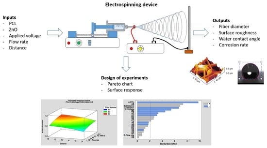
2.2. Electrospinning Procedure
2.3. Characterization Techniques
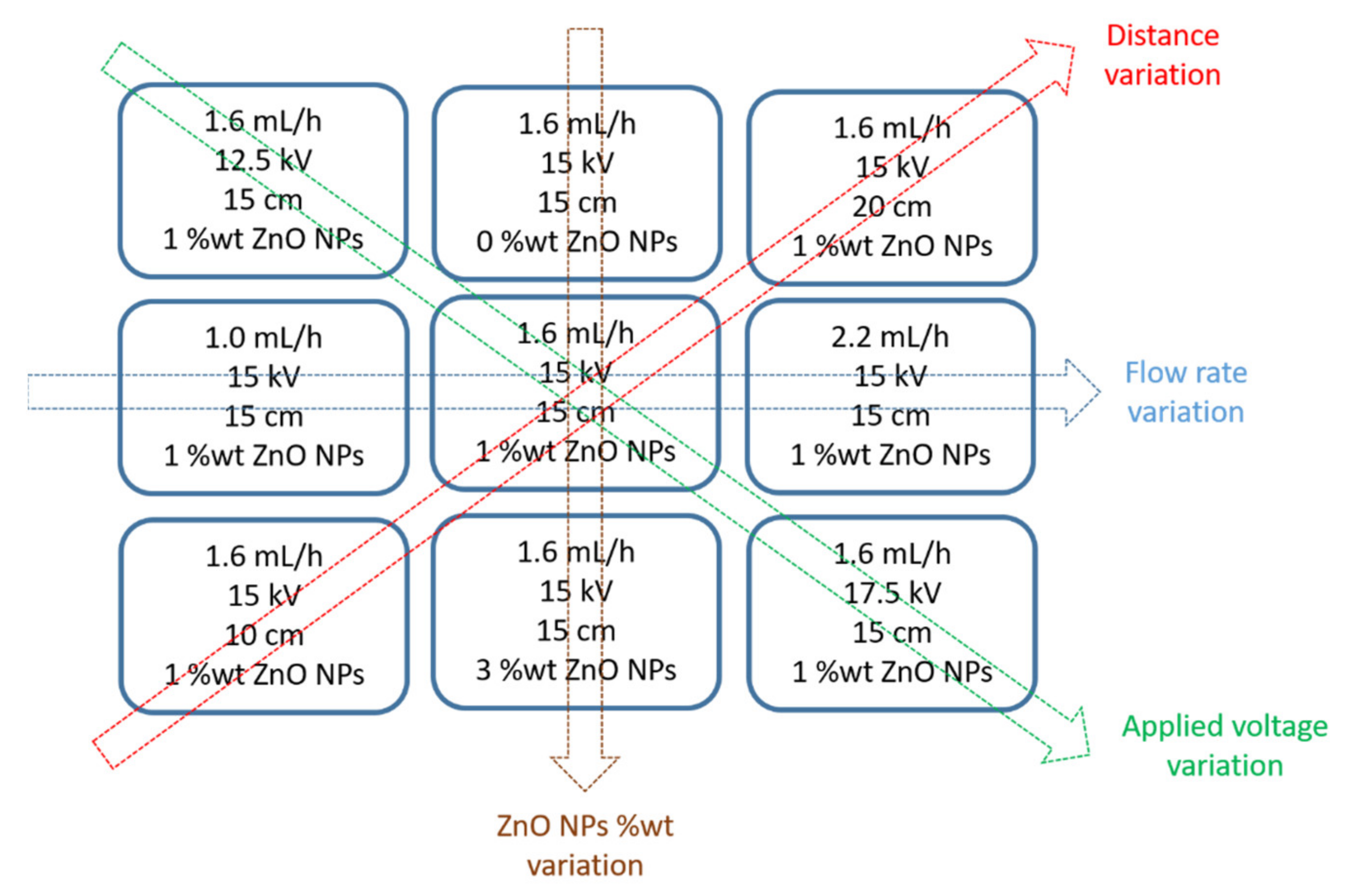
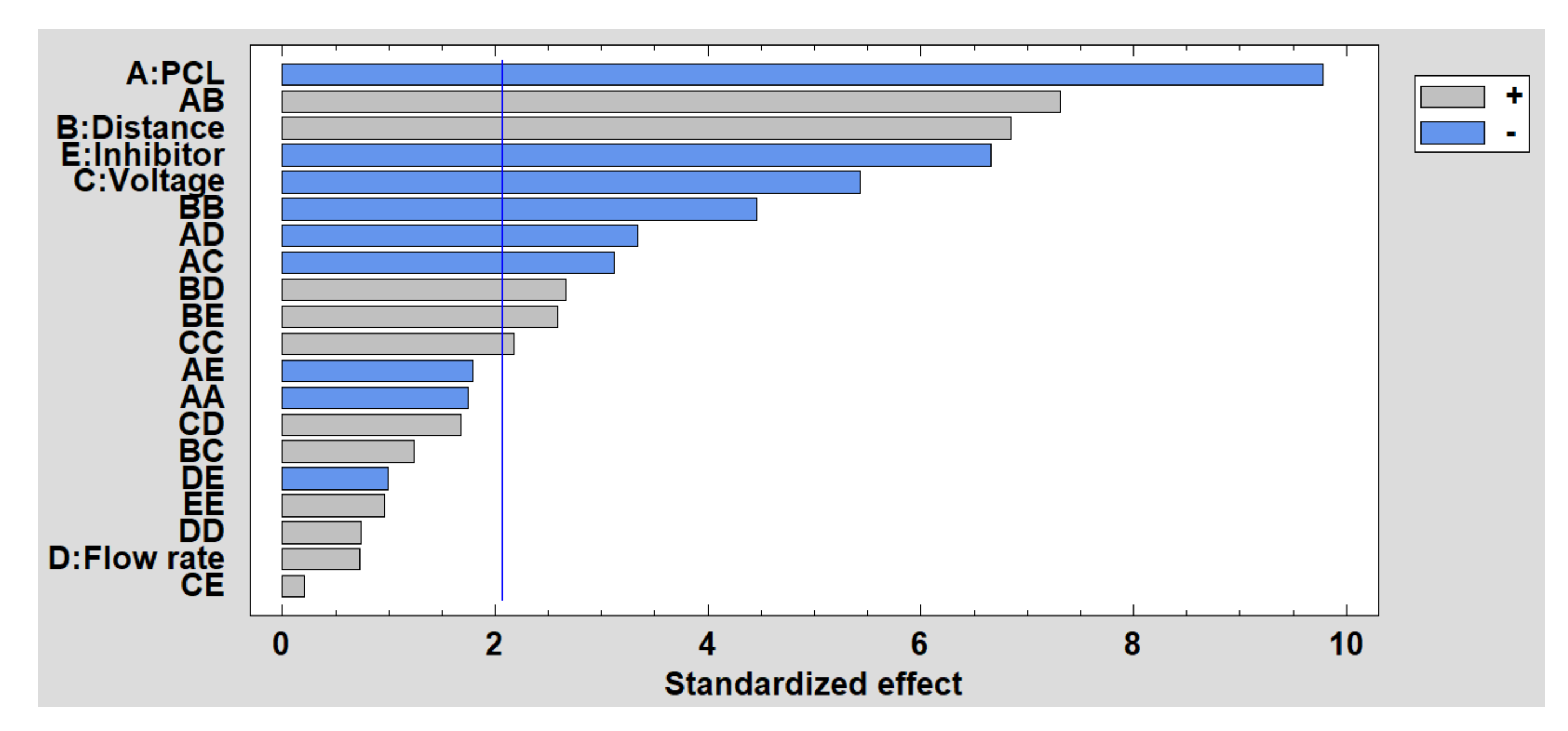
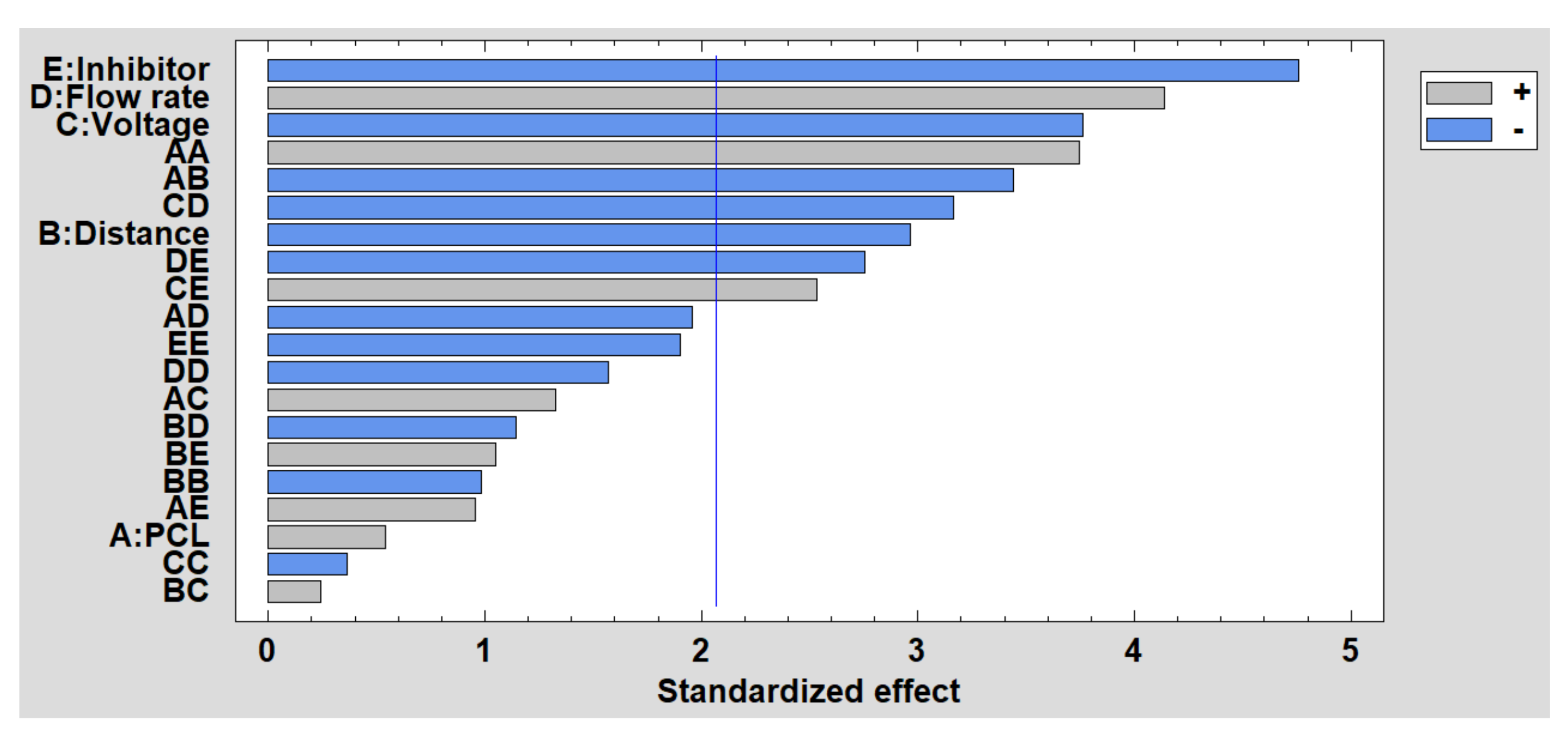
2.4. Evolution of Raw Data Using Design of Experiments
3. Results and Discussion
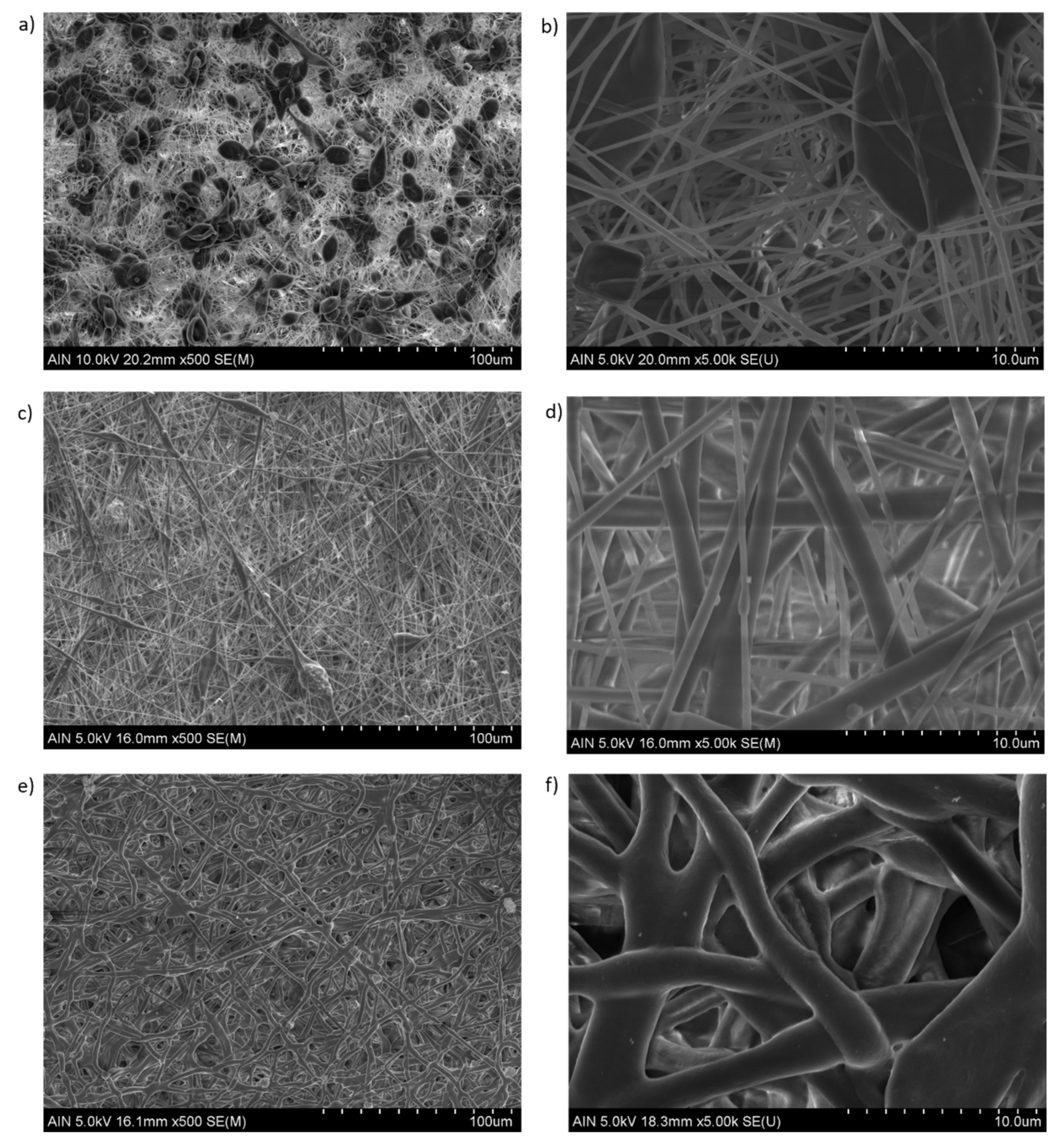
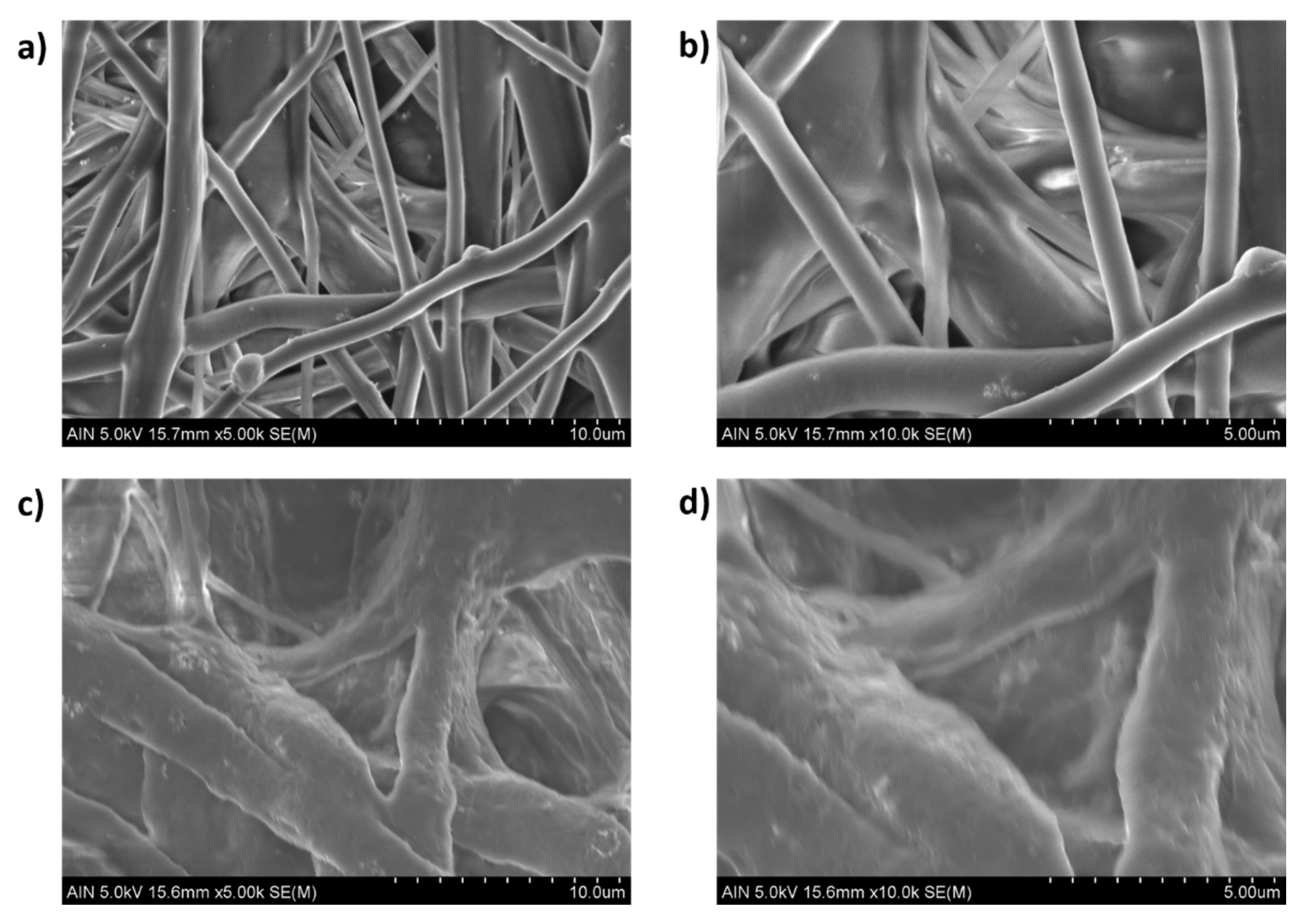
3.1. Surface Morphology
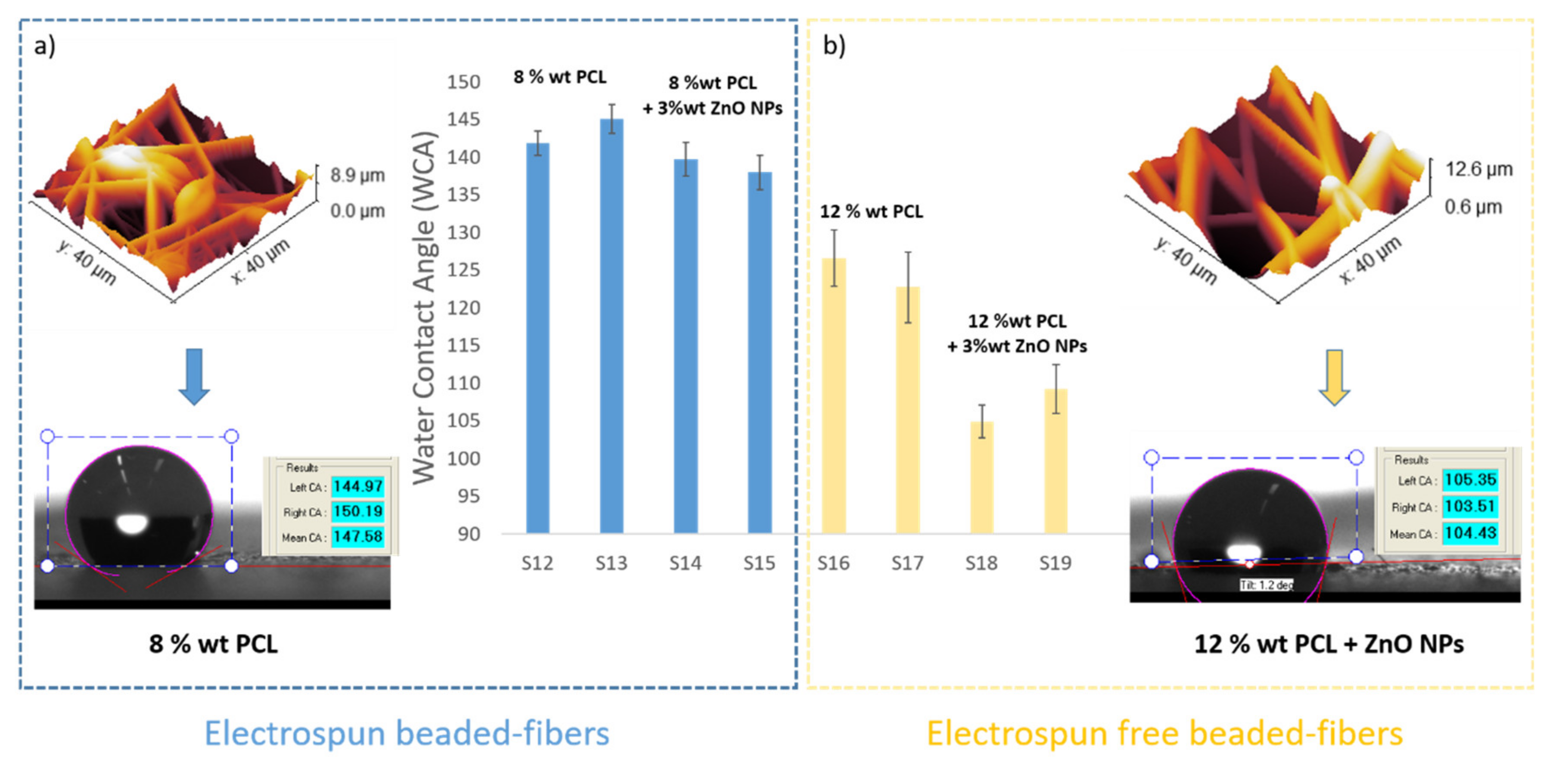
3.2. Wettability Properties
3.3. Corrosion Resistance
4. Conclusions
Supplementary Materials
Author Contributions
Funding
Conflicts of Interest
References
- Fürstner, R.; Barthlott, W.; Neinhuis, C.; Walzel, P. Wetting and Self-Cleaning Properties of Artificial Superhydrophobic Surfaces. Langmuir 2005, 21, 956–961. [Google Scholar] [CrossRef] [PubMed]
- Zhang, J.; Seeger, S. Polyester Materials with Superwetting Silicone Nanofilaments for Oil/Water Separation and Selective Oil Absorption. Adv. Funct. Mater. 2011, 21, 4699–4704. [Google Scholar] [CrossRef]
- Zhou, X.; Zhang, Z.; Xu, X.; Guo, F.; Zhu, X.; Men, X.; Ge, B. Robust and Durable Superhydrophobic Cotton Fabrics for Oil/Water Separation. ACS Appl. Mater. Interfaces 2013, 5, 7208–7214. [Google Scholar] [CrossRef]
- Scardino, A.J.; Zhang, H.; Cookson, D.J.; Lamb, R.N.; De Nys, R. The role of nano-roughness in antifouling. Biofouling 2009, 25, 757–767. [Google Scholar] [CrossRef] [PubMed]
- Momen, G.; Jafari, R.; Farzaneh, M. Ice repellency behaviour of superhydrophobic surfaces: Effects of atmospheric icing conditions and surface roughness. Appl. Surf. Sci. 2015, 349, 211–218. [Google Scholar] [CrossRef]
- Hejazi, V.; Sobolev, K.; Nosonovsky, M. From superhydrophobicity to icephobicity: Forces and interaction analysis. Sci. Rep. 2013, 3, 2194. [Google Scholar] [CrossRef] [PubMed] [Green Version]
- Farhadi, S.; Farzaneh, M.; Kulinich, S. Anti-icing performance of superhydrophobic surfaces. Appl. Surf. Sci. 2011, 257, 6264–6269. [Google Scholar] [CrossRef]
- Zhang, D.; Wang, L.; Qian, H.; Li, X. Superhydrophobic surfaces for corrosion protection: A review of recent progresses and future directions. J. Coat. Technol. Res. 2016, 13, 11–29. [Google Scholar] [CrossRef] [Green Version]
- Su, F.; Yao, K. Facile Fabrication of Superhydrophobic Surface with Excellent Mechanical Abrasion and Corrosion Resistance on Copper Substrate by a Novel Method. ACS Appl. Mater. Interfaces 2014, 6, 8762–8770. [Google Scholar] [CrossRef]
- She, Z.; Li, Q.; Wang, Z.; Li, L.; Chen, F.; Zhou, J. Researching the fabrication of anticorrosion superhydrophobic surface on magnesium alloy and its mechanical stability and durability. Chem. Eng. J. 2013, 228, 415–424. [Google Scholar] [CrossRef]
- Jiang, L.; Zhao, Y.; Zhai, J. A Lotus-Leaf-like Superhydrophobic Surface: A Porous Microsphere/Nanofiber Composite Film Prepared by Electrohydrodynamics. Angew. Chem. 2004, 43, 4338–4341. [Google Scholar] [CrossRef]
- Guo, Z.; Liu, W.; Su, B.-L. Superhydrophobic surfaces: From natural to biomimetic to functional. J. Colloid Interface Sci. 2011, 353, 335–355. [Google Scholar] [CrossRef]
- Fang, Y.; Sun, G.; Cong, Q.; Chen, G.-H.; Ren, L.-Q. Effects of Methanol on Wettability of the Non-Smooth Surface on Butterfly Wing. J. Bionic Eng. 2008, 5, 127–133. [Google Scholar] [CrossRef]
- Ma, M.; Hill, R.M. Superhydrophobic surfaces. Curr. Opin. Colloid Interface Sci. 2006, 11, 193–202. [Google Scholar] [CrossRef]
- Sun, T.; Feng, L.; Gao, X.; Jiang, L. Bioinspired surfaces with special wettability. Acc. Chem. Res. 2005, 38, 644–652. [Google Scholar] [CrossRef]
- Ishizaki, T.; Hieda, J.; Saito, N.; Saito, N.; Takai, O. Corrosion resistance and chemical stability of super-hydrophobic film deposited on magnesium alloy AZ31 by microwave plasma-enhanced chemical vapor deposition. Electrochim. Acta 2010, 55, 7094–7101. [Google Scholar] [CrossRef]
- Sarkar, D.; Farzaneh, M.; Paynter, R. Wetting and superhydrophobic properties of PECVD grown hydrocarbon and fluorinated-hydrocarbon coatings. Appl. Surf. Sci. 2010, 256, 3698–3701. [Google Scholar] [CrossRef] [Green Version]
- Yang, Z.; Tian, Y.L.; Yang, C.J.; Wang, F.J.; Liu, X.P. Modification of wetting property of Inconel 718 surface by nanosecond laser texturing. Appl. Surf. Sci. 2017, 414, 313–324. [Google Scholar] [CrossRef] [Green Version]
- Pan, H.H.; Wang, Z.; Fan, W.Z.; Wang, C.W.; Li, H.J.; Bai, F.; Qian, J.; Zhao, Q.Z. Superhydrophobic Titanium Surface Micro/Nanostructures Induced by Femtosecond Laser. Chin. J. Lasers 2016, 43, 802002. [Google Scholar]
- Becker, C.; Petersen, J.; Mertz, G.; Ruch, D.; Dinia, A. High Superhydrophobicity Achieved on Poly(ethylene terephthalate) by Innovative Laser-Assisted Magnetron Sputtering. J. Phys. Chem. C 2011, 115, 10675–10681. [Google Scholar] [CrossRef]
- Qian, B.; Shen, Z. Fabrication of Superhydrophobic Surfaces by Dislocation-Selective Chemical Etching on Aluminum, Copper, and Zinc Substrates. Langmuir 2005, 21, 9007–9009. [Google Scholar] [CrossRef]
- Lin, J.; Cai, Y.; Wang, X.; Ding, B.; Yu, J.; Wang, M. Fabrication of biomimetic superhydrophobic surfaces inspired by lotus leaf and silver ragwort leaf. Nanoscale 2011, 3, 1258–1262. [Google Scholar] [CrossRef]
- Bhardwaj, N.; Kundu, S.C. Electrospinning: A fascinating fiber fabrication technique. Biotechnol. Adv. 2010, 28, 325–347. [Google Scholar] [CrossRef]
- Yarin, A.L.; Koombhongse, S.; Reneker, D.H. Taylor cone and jetting from liquid droplets in electrospinning of nanofibers. J. Appl. Phys. 2001, 90, 4836–4846. [Google Scholar] [CrossRef] [Green Version]
- Reneker, D.; Yarin, A.; Zussman, E.; Xu, H. Electrospinning of Nanofibers from Polymer Solutions and Melts. Adv. Appl. Mech. 2007, 41, 43–346. [Google Scholar]
- Reneker, D.H.; Yarin, A.L. Electrospinning jets and polymer nanofibers. Polymer 2008, 49, 2387–2425. [Google Scholar] [CrossRef] [Green Version]
- Pillay, V.; Dott, C.; Choonara, Y.; Tyagi, C.; Tomar, L.; Kumar, P.; du Toit, L.; Ndesendo, V.M.K. A Review of the Effect of Processing Variables on the Fabrication of Electrospun Nanofibers for Drug Delivery Applications. J. Nanomater. 2013, 2013, 789289. [Google Scholar] [CrossRef] [Green Version]
- Szewczyk, P.K.; Stachewicz, U. The impact of relative humidity on electrospun polymer fibers: From structural changes to fiber morphology. Adv. Colloid Interface Sci. 2020, 286, 102315. [Google Scholar] [CrossRef]
- Ojha, G.P.; Pant, B.; Acharya, J.; Park, M. An electrochemically reduced ultra-high mass loading three-dimensional carbon nanofiber network: A high energy density symmetric supercapacitor with a reproducible and stable cell voltage of 2.0 V. Nanoscale 2021, 13, 19537–19548. [Google Scholar] [CrossRef] [PubMed]
- Nezarati, R.M.; Eifert, M.B.; Cosgriff-Hernandez, E. Effects of Humidity and Solution Viscosity on Electrospun Fiber Morphology. Tissue Eng. Part C Methods 2013, 19, 810–819. [Google Scholar] [CrossRef] [PubMed] [Green Version]
- Putti, M.; Simonet, M.; Solberg, R.; Peters, G.W. Electrospinning poly(ε-caprolactone) under controlled environmental conditions: Influence on fiber morphology and orientation. Polymer 2015, 63, 189–195. [Google Scholar] [CrossRef]
- Şimşek, M. Tuning surface texture of electrospun polycaprolactone fibers: Effects of solvent systems and relative humidity. J. Mater. Res. 2020, 35, 332–342. [Google Scholar] [CrossRef]
- Rivero, P.J.; Redin, D.M.; Rodríguez, R.J. Electrospinning: A Powerful Tool to Improve the Corrosion Resistance of Metallic Surfaces Using Nanofibrous Coatings. Metals 2020, 10, 350. [Google Scholar] [CrossRef] [Green Version]
- Gunatillake, P.A.; Adhikari, R. Biodegradable synthetic polymers for tissue engineering. Eur. Cells Mater. 2003, 5, 1–16. [Google Scholar] [CrossRef]
- Zhang, G.; Wang, P.; Zhang, X.; Xiang, C.; Li, L. Preparation of hierarchically structured PCL superhydrophobic membrane via alternate electrospinning/electrospraying techniques. J. Polym. Sci. Part B Polym. Phys. 2019, 57, 421–430. [Google Scholar] [CrossRef]
- Premanathan, M.; Karthikeyan, K.; Jeyasubramanian, K.; Manivannan, G. Selective toxicity of ZnO nanoparticles toward Gram-positive bacteria and cancer cells by apoptosis through lipid peroxidation. Nanomed. Nanotechnol. Biol. Med. 2011, 7, 184–192. [Google Scholar] [CrossRef] [PubMed]
- Mirzaei, H.; Darroudi, M. Zinc oxide nanoparticles: Biological synthesis and biomedical applications. Ceram. Int. 2017, 43, 907–914. [Google Scholar] [CrossRef]
- Mishra, P.K.; Mishra, H.; Ekielski, A.; Talegaonkar, S.; Vaidya, B. Zinc oxide nanoparticles: A promising nanomaterial for biomedical applications. Drug Discov. Today 2017, 22, 1825–1834. [Google Scholar] [CrossRef]
- Augustine, R.; Dominic, E.A.; Reju, I.; Kaimal, B.; Kalarikkal, N.; Thomas, S. Electrospun polycaprolactone membranes incorporated with ZnO nanoparticles as skin substitutes with enhanced fibroblast proliferation and wound healing. RSC Adv. 2014, 4, 24777–24785. [Google Scholar] [CrossRef]
- Augustine, R.; Dominic, E.A.; Reju, I.; Kaimal, B.; Kalarikkal, N.; Thomas, S. Investigation of angiogenesis and its mechanism using zinc oxide nanoparticle-loaded electrospun tissue engineering scaffolds. RSC Adv. 2014, 4, 51528–51536. [Google Scholar] [CrossRef]
- Thompson, C.J.; Chase, G.; Yarin, A.; Reneker, D. Effects of parameters on nanofiber diameter determined from electrospinning model. Polymer 2007, 48, 6913–6922. [Google Scholar] [CrossRef]
- Iribarren, A.; Rivero, P.J.; Berlanga, C.; Larumbe, S.; Miguel, A.; Palacio, J.F.; Rodriguez, R. Multifunctional protective PVC-ZnO nanocomposite coatings deposited on aluminum alloys by electrospinning. Coatings 2019, 9, 216. [Google Scholar] [CrossRef] [Green Version]
- Huang, T.-C.; Yeh, T.-C.; Huang, H.-Y.; Ji, W.-F.; Lin, T.-C.; Chen, C.-A.; Yang, T.-I.; Yeh, J.-M. Electrochemical investigations of the anticorrosive and electrochromic properties of electroactive polyamide. Electrochim. Acta 2012, 63, 185–191. [Google Scholar] [CrossRef]
- Yuan, R.; Wu, S.; Yu, P.; Wang, B.; Mu, L.; Zhang, X.; Zhu, Y.; Wang, B.; Wang, H.; Zhu, J. Superamphiphobic and Electroactive Nanocomposite toward Self-Cleaning, Antiwear, and Anticorrosion Coatings. ACS Appl. Mater. Interfaces 2016, 8, 12481–12493. [Google Scholar] [CrossRef]
- Huang, H.-Y.; Huang, T.-C.; Yeh, T.-C.; Tsai, C.-Y.; Lai, C.-L.; Tsai, M.-H.; Yeh, J.-M.; Chou, Y.-C. Advanced anticorrosive materials prepared from amine-capped aniline trimer-based electroactive polyimide-clay nanocomposite materials with synergistic effects of redox catalytic capability and gas barrier properties. Polymer 2011, 52, 2391–2400. [Google Scholar] [CrossRef]
- Lee, K.H.; Kim, H.Y.; La, Y.M.; Lee, D.R.; Sung, N.H. Influence of a mixing solvent with tetrahydrofuran and N,N-dimethylformamide on electrospun poly(vinyl chloride) nonwoven mats. J. Polym. Sci. Part B Polym. Phys. 2002, 40, 2259–2268. [Google Scholar] [CrossRef]
- Megelski, S.; Stephens, J.S.; Chase, A.D.B.; Rabolt, J.F. Micro- and Nanostructured Surface Morphology on Electrospun Polymer Fibers. Macromolecules 2002, 35, 8456–8466. [Google Scholar] [CrossRef]
- Katti, D.S.; Robinson, K.W.; Ko, F.K.; Laurencin, C.T. Bioresorbable nanofiber-based systems for wound healing and drug delivery: Optimization of fabrication parameters. J. Biomed. Mater. Res. 2004, 70B, 286–296. [Google Scholar] [CrossRef]
- Sill, T.J.; Von Recum, H.A. Electrospinning: Applications in drug delivery and tissue engineering. Biomaterials 2008, 29, 1989–2006. [Google Scholar] [CrossRef]
- Agarwal, P.; Mishra, P.K.; Srivastava, P. Statistical optimization of the electrospinning process for chitosan/polylactide nanofabrication using response surface methodology. J. Mater. Sci. 2012, 47, 4262–4269. [Google Scholar] [CrossRef]
- Rivero, P.J.; Rosagaray, I.; Fuertes, J.P.; Palacio, J.F.; Rodríguez, R.J. Designing Multifunctional Protective PVC Electrospun Fibers with Tunable Properties. Polymers 2020, 12, 2086. [Google Scholar] [CrossRef]
- Pham, L.Q.; Uspenskaya, M.; Olekhnovich, R.; Bernal, R.O. A Review on Electrospun PVC Nanofibers: Fabrication, Properties, and Application. Fibers 2021, 9, 12. [Google Scholar] [CrossRef]
- Doshi, J.; Reneker, D.H. Electrospinning process and applications of electrospun fibers. J. Electrost. 1995, 35, 151–160. [Google Scholar] [CrossRef]
- Frenot, A.; Chronakis, I.S. Polymer nanofibers assembled by electrospinning. Curr. Opin. Colloid Interface Sci. 2003, 8, 64–75. [Google Scholar] [CrossRef]
- Affandi, N.D.N.; Ibrahim, N.A.; Fadil, F. Tuning surface roughness of electrospun poly caprolactone fibres by single solvent electrospinning system. Dig. J. Nanomater. Biostructures 2020, 15, 1069–1074. [Google Scholar]
- Gade, H.; Nikam, S.; Chase, G.G.; Reneker, D.H. Effect of electrospinning conditions on β-phase and surface charge potential of PVDF fibers. Polymer 2021, 228, 123902. [Google Scholar] [CrossRef]
- Tungprapa, S.; Puangparn, T.; Weerasombut, M.; Jangchud, I.; Fakum, P.; Semongkhol, S.; Meechaisue, C.; Supaphol, P. Electrospun cellulose acetate fibers: Effect of solvent system on morphology and fiber diameter. Cellulose 2007, 14, 563–575. [Google Scholar] [CrossRef]
- Hsu, C.-M.; Shivkumar, S. Nano-sized beads and porous fiber constructs of Poly(ε-caprolactone) produced by electrospinning. J. Mater. Sci. 2004, 39, 3003–3013. [Google Scholar] [CrossRef]
- Khan, T.; Mamun, A. Effect of Different Solvent Systems on Fiber Morphology and Property of Electrospun PCL Nano Fibers. Tekstil Mühendis 2021, 28, 61–76. [Google Scholar] [CrossRef]
- Laiva, A.L.; Venugopal, J.R.; Sridhar, S.; Rangarajan, B.; Navaneethan, B.; Ramakrishna, S. Novel and simple methodology to fabricate porous and buckled fibrous structures for biomedical applications. Polymer 2014, 55, 5837–5842. [Google Scholar] [CrossRef]
- Katsogiannis, K.A.G.; Vladisavljevic, G.; Georgiadou, S. Porous electrospun polycaprolactone (PCL) fibres by phase separation. Eur. Polym. J. 2015, 69, 284–295. [Google Scholar] [CrossRef] [Green Version]
- Augustine, R.; Malik, H.; Singhal, D.K.; Mukherjee, A.; Malakar, D.; Kalarikkal, N.; Thomas, S. Electrospun polycaprolactone/ZnO nanocomposite membranes as biomaterials with antibacterial and cell adhesion properties. J. Polym. Res. 2014, 21, 347. [Google Scholar] [CrossRef]
- Zong, X.; Kim, K.; Fang, D.; Ran, S.; Hsiao, B.S.; Chu, B. Structure and process relationship of electrospun bioabsorbable nanofiber membranes. Polymer 2002, 43, 4403–4412. [Google Scholar] [CrossRef]
- Fong, H.; Chun, I.; Reneker, D.H. Beaded nanofibers formed during electrospinning. Polymer 1999, 40, 4585–4592. [Google Scholar] [CrossRef]
- Rodríguez-Tobías, H.; Morales, G.; Ledezma, A.; Romero, J.; Grande, D. Novel antibacterial electrospun mats based on poly(d,l-lactide) nanofibers and zinc oxide nanoparticles. J. Mater. Sci. 2014, 49, 8373–8385. [Google Scholar] [CrossRef]
- Zhang, G.; Wang, P.; Zhang, X.; Xiang, C.; Li, L. The preparation of PCL/MSO/SiO2 hierarchical superhydrophobic mats for oil-water separation by one-step method. Eur. Polym. J. 2019, 116, 386–393. [Google Scholar] [CrossRef]
- Semiromi, F.B.; Nejaei, A.; Shojaee, M. Effect of Methanol Concentration on the Morphology and Wettability of Electrospun Nanofibrous Membranes Based on Polycaprolactone for Oil-water Separation. Fibers Polym. 2019, 20, 2453–2460. [Google Scholar] [CrossRef]
- Kim, J.; Mousa, H.M.; Park, C.H.; Kim, C.S. Enhanced corrosion resistance and biocompatibility of AZ31 Mg alloy using PCL/ZnO NPs via electrospinning. Appl. Surf. Sci. 2017, 396, 249–258. [Google Scholar] [CrossRef]
- Prado-Prone, G.; Silva-Bermudez, P.; García-Macedo, J.A.; Almaguer-Flores, A.; Ibarra, C.; Velasquillo-Martínez, C. Photocatalytic antibacterial effect of ZnO nanoparticles into coaxial electrospun PCL fibers to prevent infections from skin injuries. In Proceedings of the Energy-Based Treatment of Tissue and Assessment IX, San Francisco, CA, USA, 28 January–2 February 2017; Volume 10066, p. 1006608. [Google Scholar]
- Shitole, A.A.; Raut, P.W.; Sharma, N.; Giram, P.; Khandwekar, A.P.; Garnaik, B. Electrospun polycaprolactone/hydroxyapatite/ZnO nanofibers as potential biomaterials for bone tissue regeneration. J. Mater. Sci. Mater. Med. 2019, 30, 51. [Google Scholar] [CrossRef]
- Felice, B.; Sánchez, M.A.; Socci, M.C.; Sappia, L.D.; Gómez, M.I.; Cruz, M.K.; Felice, C.J.; Martí, M.; Pividori, M.I.; Simonelli, G.; et al. Controlled degradability of PCL-ZnO nanofibrous scaffolds for bone tissue engineering and their antibacterial activity. Mater. Sci. Eng. C 2018, 93, 724–738. [Google Scholar] [CrossRef] [Green Version]
- Pant, H.R.; Neupane, M.P.; Pant, B.; Panthi, G.; Oh, H.-J.; Lee, M.H.; Kim, H.Y. Fabrication of highly porous poly (ɛ-caprolactone) fibers for novel tissue scaffold via water-bath electrospinning. Colloids Surf. B Biointerfaces 2011, 88, 587–592. [Google Scholar] [CrossRef] [PubMed]
- Ma, M.; Mao, Y.; Gupta, M.; Gleason, K.K.; Rutledge, G.C. Superhydrophobic Fabrics Produced by Electrospinning and Chemical Vapor Deposition. Macromolecules 2005, 38, 9742–9748. [Google Scholar] [CrossRef]
- Daskalova, A.; Angelova, L.; Filipov, E.; Aceti, D.; Mincheva, R.; Carrete, X.; Kerdjoudj, H.; Dubus, M.; Chevrier, J.; Trifonov, A.; et al. Biomimetic Hierarchical Structuring of PLA by Ultra-Short Laser Pulses for Processing of Tissue Engineered Matrices: Study of Cellular and Antibacterial Behavior. Polymers 2021, 13, 2577. [Google Scholar] [CrossRef]
- Darmanin, T.; Guittard, F. Recent advances in the potential applications of bioinspired superhydrophobic materials. J. Mater. Chem. A 2014, 2, 16319–16359. [Google Scholar] [CrossRef]
- Vicente, A.; Rivero, P.J.; Palacio, J.F.; Rodríguez, R. The Role of the Fiber/Bead Hierarchical Microstructure on the Properties of PVDF Coatings Deposited by Electrospinning. Polymers 2021, 13, 464. [Google Scholar] [CrossRef] [PubMed]
- Dong, Y. Effect of the Morphology of Electrospun Polyvinylidene Fluoride Nanofiber on Corrosion Property of Q345 Steel. Int. J. Electrochem. Sci. 2017, 12, 11064–11076. [Google Scholar] [CrossRef]
- Cui, M.; Xu, C.; Shen, Y.; Tian, H.; Feng, H.; Li, J. Electrospinning superhydrophobic nanofibrous poly(vinylidene fluoride)/stearic acid coatings with excellent corrosion resistance. Thin Solid Films 2018, 657, 88–94. [Google Scholar] [CrossRef]
- Zhao, Y.; Xing, C.; Zhang, Z.; Yu, L. Superhydrophobic polyaniline/polystyrene micro/nanostructures as anticorrosion coatings. React. Funct. Polym. 2017, 119, 95–104. [Google Scholar] [CrossRef]
- Li, J.; Guan, P.; Li, M.; Zhang, Y.; Cheng, P.; Jia, R. Anticorrosive superhydrophobic polystyrene-coated mesh for continuous oil spill clean-up. New J. Chem. 2017, 41, 4862–4868. [Google Scholar] [CrossRef]
- Hanas, T.; Kumar, T.S.; Perumal, G.; Doble, M. Tailoring degradation of AZ31 alloy by surface pre-treatment and electrospun PCL fibrous coating. Mater. Sci. Eng. C 2016, 65, 43–50. [Google Scholar] [CrossRef]
- Grignard, B.; Vaillant, A.; de Coninck, J.; Piens, M.; Jonas, A.M.; Detrembleur, C.; Jerome, C. Electrospinning of a Functional Perfluorinated Block Copolymer as a Powerful Route for Imparting Superhydrophobicity and Corrosion Resistance to Aluminum Substrates. Langmuir 2011, 27, 335–342. [Google Scholar] [CrossRef] [PubMed]
- Albistur, A.; Rivero, P.; Esparza, J.; Rodríguez, R. Evaluation of the Photocatalytic Activity and Anticorrosion Performance of Electrospun Fibers Doped with Metallic Oxides. Polymers 2021, 13, 2011. [Google Scholar] [CrossRef] [PubMed]
- Radwan, A.B.; Mohamed, A.M.; Abdullah, A.M.; Al-Maadeed, S. Corrosion protection of electrospun PVDF–ZnO superhydrophobic coating. Surf. Coat. Technol. 2016, 289, 136–143. [Google Scholar] [CrossRef]
- Bahgat, A.; Mohamed, A.; Abdullah, A.; Almaadeed, M. Superhydrophobic and Corrosion Behavior of Electrospun PVDF-ZnO Coating. ECS Trans. 2015, 64, 57–67. [Google Scholar] [CrossRef]
- Rivero, P.J.; Iribarren, A.; Larumbe, S.; Palacio, J.F.; Rodríguez, R. A comparative study of multifunctional coatings based on electrospun fibers with incorporated ZnO nanoparticles. Coatings 2019, 9, 367. [Google Scholar] [CrossRef] [Green Version]
- AlFalah, M.G.K.; Kamberli, E.; Abbar, A.H.; Kandemirli, F.; Saracoglu, M. Corrosion performance of electrospinning nanofiber ZnO-NiO-CuO/polycaprolactone coated on mild steel in acid solution. Surf. Interfaces 2020, 21, 100760. [Google Scholar] [CrossRef]


| PCL | ZnO NPs | Flow Rate | Applied Voltage | Distance |
|---|---|---|---|---|
| 8, 10, 12 wt% | 0, 1, 3 wt% | 1, 1.6, 2.2 mL/h | 12.5, 15, 17.5 kV | 10, 15, 20 cm |
| Factor | High Level | Low Level |
|---|---|---|
| (A) PCL concentration (%) | 12 | 8 |
| (B) Distance (cm) | 20 | 10 |
| (C) Voltage (kV) | 17.5 | 12.5 |
| (D) Flow rate (µL/h) | 2200 | 1000 |
| (E) Inhibitor presence | 1 | −1 |
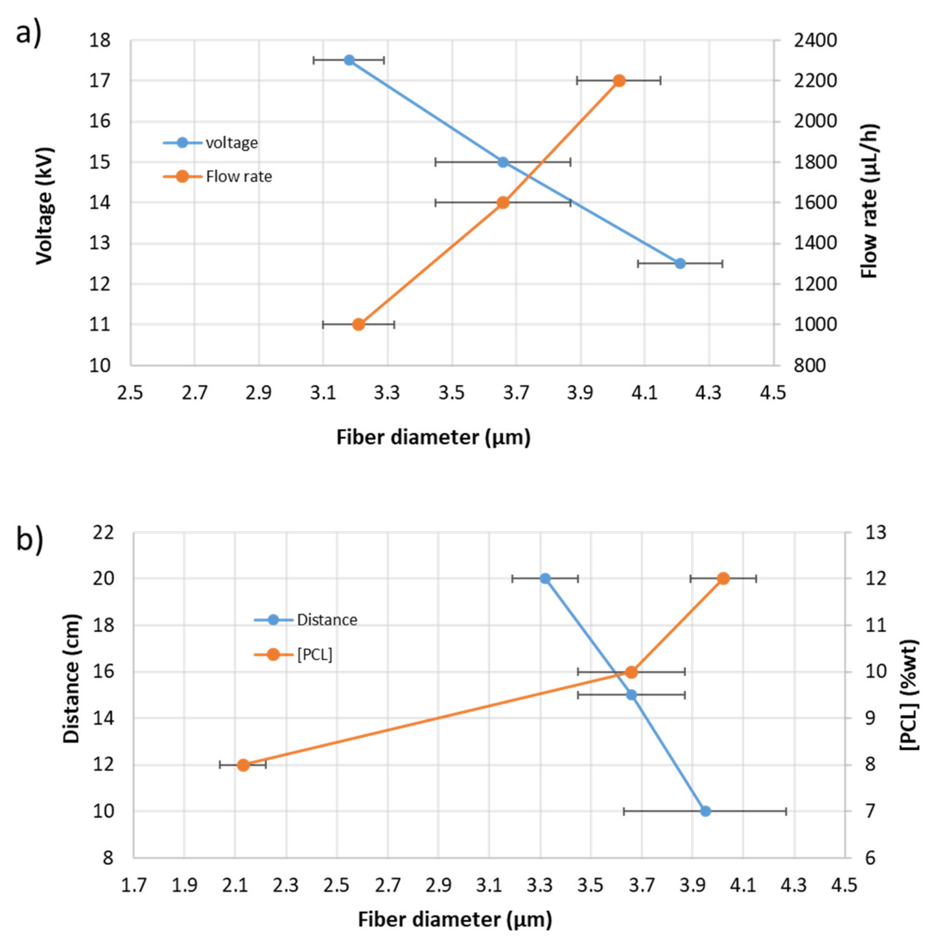
| Number of Sample | PCL (wt%) | ZnO NPs (wt%) | Distance (cm) | Voltage (kV) | Flow Rate (µL/h) | Fiber Diameter (µm) |
|---|---|---|---|---|---|---|
| S1 | 10 | 1 | 15 | 15 | 1000 | 3.21 ± 0.11 |
| S2 | 10 | 1 | 15 | 12.5 | 1600 | 4.21 ± 0.13 |
| S3 | 10 | 1 | 15 | 15 | 1600 | 3.66 ± 0.21 |
| S4 | 10 | 1 | 15 | 17.5 | 1600 | 3.18 ± 0.11 |
| S5 | 10 | 1 | 15 | 15 | 2200 | 4.02 ± 0.13 |
| S6 | 10 | 1 | 10 | 15 | 1600 | 3.95 ± 0.32 |
| S7 | 10 | 1 | 20 | 15 | 1600 | 3.32 ± 0.07 |
| S8 | 10 | 0 | 15 | 15 | 1600 | 3.68 ± 0.16 |
| S9 | 10 | 3 | 15 | 15 | 1600 | 3.71 ± 0.11 |
| S10 | 8 | 1 | 15 | 15 | 1600 | 2.13 ± 0.09 |
| S11 | 12 | 1 | 15 | 15 | 1600 | 4.11 ± 0.08 |
| Number of Sample | PCL (wt%) | ZnO NPs (wt%) | Flow Rate (µL/h) | Roughness Sa (µm) | Fiber Diameter (µm) | WCA (°) | Presence of Beads |
|---|---|---|---|---|---|---|---|
| S12 | 8 | 0 | 1000 | 1.76 ± 0.10 | 2.11 ± 0.28 | 141.86 ± 1.61 | Ok |
| S13 | 8 | 0 | 2200 | 1.88 ± 0.09 | 2.35 ± 0.15 | 145.09 ± 1.90 | Ok |
| S14 | 8 | 3 | 1000 | 2.09 ± 0.04 | 2.04 ± 0.21 | 139.74 ± 2.21 | Ok |
| S15 | 8 | 3 | 2200 | 2.02 ± 0.10 | 2.44 ± 0.19 | 137.98 ± 2.29 | Ok |
| S16 | 12 | 0 | 1000 | 1.49 ± 0.03 | 3.03 ± 0.51 | 126.59 ± 3.71 | No |
| S17 | 12 | 0 | 2200 | 1.74 ± 0.04 | 3.48 ± 0.44 | 122.71 ± 4.66 | No |
| S18 | 12 | 3 | 1000 | 1.67 ± 0.14 | 3.70 ± 0.44 | 104.92 ± 2.21 | No |
| S19 | 12 | 3 | 2200 | 1.58 ± 0.13 | 4.04 ± 0.29 | 109.22 ± 3.21 | No |
| Sample | βa (mV/dec) | βc (mV/dec) | Ecorr (V) | icorr (A) | Corrosion Rate (mm/Year) |
|---|---|---|---|---|---|
| Reference steel | 0.19443 | 0.2284 | −0.10592 | 1.91E-05 | 0.011831 |
| S12 | 0.6528 | 0.15769 | −0.27102 | 1.4094E-06 | 0.0073271 |
| S13 | 0.40458 | 0.079877 | −0.20795 | 1.1164E-06 | 0.0058039 |
| S14 | 0.15224 | 0.048841 | −0.079322 | 3.1208E-08 | 0.00016224 |
| S15 | 0.17886 | 0.089351 | −0.30841 | 2.1332E-06 | 0.0013112 |
| S16 | 0.24296 | 0.13855 | −0.27897 | 3.0928E-06 | 0.009079 |
| S17 | 0.72226 | 0.15059 | −0.22431 | 1.484E-06 | 0.0061553 |
| S18 | 0.41468 | 0.097008 | −0.28954 | 2.1699E-06 | 0.0013338 |
| S19 | 0.51866 | 0.24543 | −0.34638 | 1.0355E-07 | 0.00095943 |
Publisher’s Note: MDPI stays neutral with regard to jurisdictional claims in published maps and institutional affiliations. |
© 2021 by the authors. Licensee MDPI, Basel, Switzerland. This article is an open access article distributed under the terms and conditions of the Creative Commons Attribution (CC BY) license (https://creativecommons.org/licenses/by/4.0/).
Share and Cite
Rivero, P.J.; Fuertes, J.P.; Vicente, A.; Mata, Á.; Palacio, J.F.; Monteserín, M.; Rodríguez, R. Modeling Experimental Parameters for the Fabrication of Multifunctional Surfaces Composed of Electrospun PCL/ZnO-NPs Nanofibers. Polymers 2021, 13, 4312. https://doi.org/10.3390/polym13244312
Rivero PJ, Fuertes JP, Vicente A, Mata Á, Palacio JF, Monteserín M, Rodríguez R. Modeling Experimental Parameters for the Fabrication of Multifunctional Surfaces Composed of Electrospun PCL/ZnO-NPs Nanofibers. Polymers. 2021; 13(24):4312. https://doi.org/10.3390/polym13244312
Chicago/Turabian StyleRivero, Pedro J., Juan P. Fuertes, Adrián Vicente, Álvaro Mata, José F. Palacio, María Monteserín, and Rafael Rodríguez. 2021. "Modeling Experimental Parameters for the Fabrication of Multifunctional Surfaces Composed of Electrospun PCL/ZnO-NPs Nanofibers" Polymers 13, no. 24: 4312. https://doi.org/10.3390/polym13244312
APA StyleRivero, P. J., Fuertes, J. P., Vicente, A., Mata, Á., Palacio, J. F., Monteserín, M., & Rodríguez, R. (2021). Modeling Experimental Parameters for the Fabrication of Multifunctional Surfaces Composed of Electrospun PCL/ZnO-NPs Nanofibers. Polymers, 13(24), 4312. https://doi.org/10.3390/polym13244312