
Effect of Molecular Weight and Nanoarchitecture of Chitosan and Polycaprolactone Electrospun Membranes on Physicochemical and Hemocompatible Properties for Possible Wound Dressing

 ,
,  , and
, and
Abstract
1. Introduction
2. Materials and Methods
2.1. Materials
2.2. Preparation of the Material
2.2.1. Preparation of Working Solutions
2.2.2. Electrospinning of the PCL/ChMMW and PCL/ChLMW Membranes
2.3. Physicochemical Characterization of Biocomposite Membranes
2.3.1. Scanning Electron Microscopy (SEM)
2.3.2. Fourier Transform Infrared Spectroscopy (FTIR)
2.3.3. Dynamic Mechanical Analysis (DMA)
2.3.4. Contact Angle Wettability
2.3.5. Degradation
2.3.6. Static Permeability Test
2.4. Biological Evaluation
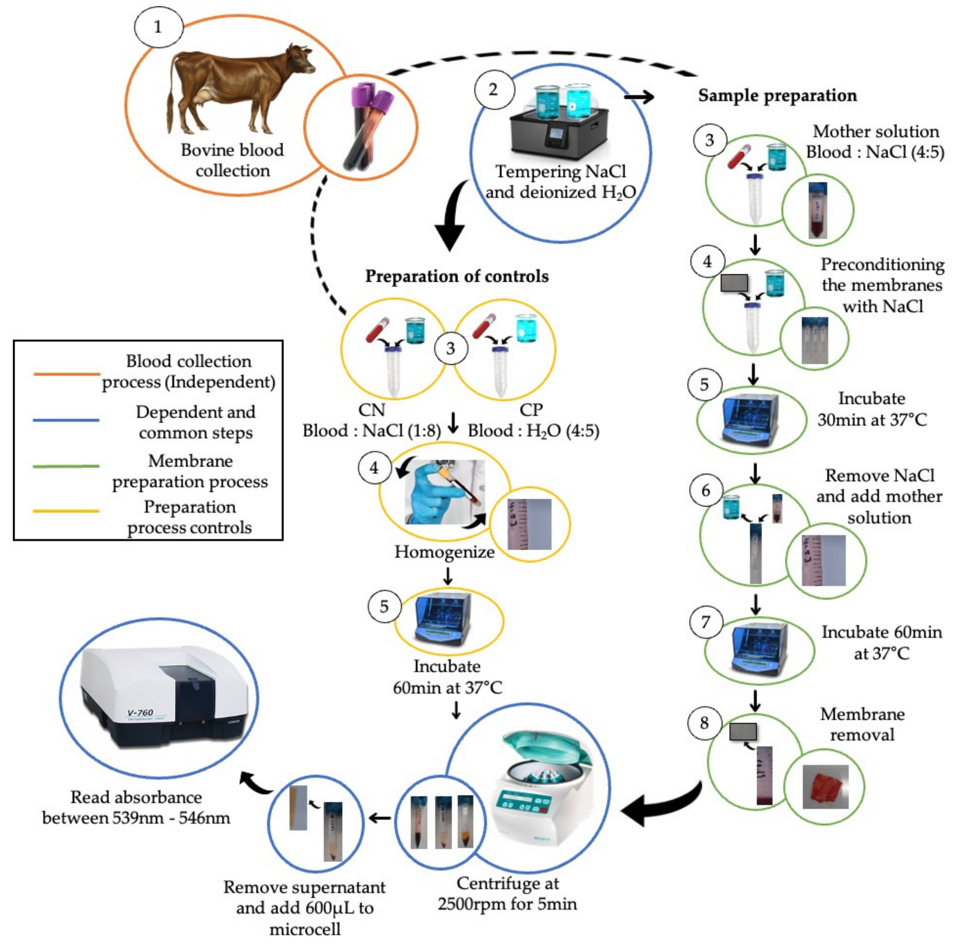
2.4.1. Hemolytic Test
2.4.2. In Vitro Model
2.4.3. Cell Viability
2.5. Statistical Analysis
3. Results and Discussion
3.1. Scanning Electron Microscopy
3.2. Fourier Transform Infrared Spectroscopy
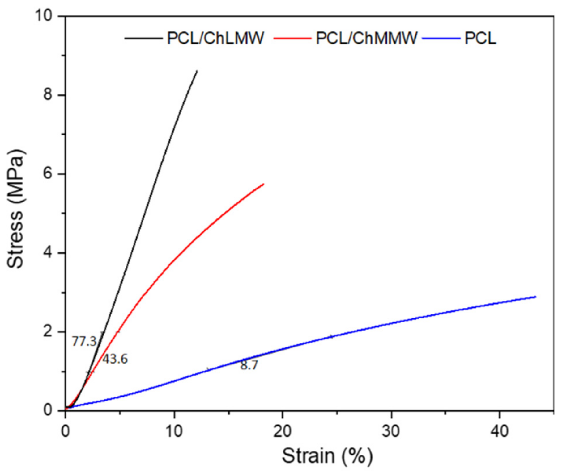
3.3. Dynamic Mechanical Analysis
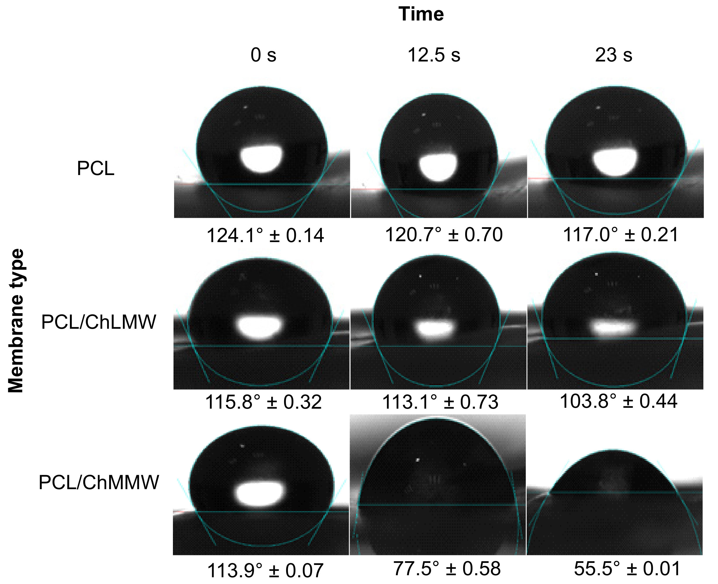
3.4. Contact Angle Wettability
3.5. Degradation
3.6. Static Permeability Test
3.7. Hemolytic Test
3.8. Cell Viability
4. Conclusions
Author Contributions
Funding
Institutional Review Board Statement
Informed Consent Statement
Data Availability Statement
Acknowledgments
Conflicts of Interest
References
- Estrada, C.; Paz, A.C.; López, L.E. Ingeniería de tejido óseo: Consideraciones básicas. Rev. EIA Esc. Antioq. 2009, 42, 249–261. [Google Scholar]
- Zarei, M.; Samimi, A.; Khorram, M.; Abdi, M.M.; Golestaneh, S.I. Fabrication and characterization of conductive polypyrrole/chitosan/collagen electrospun nanofiber scaffold for tissue engineering application. Int. J. Biol. Macromol. 2021, 168, 175–186. [Google Scholar] [CrossRef] [PubMed]
- Poddar, D.; Jain, P.; Rawat, S.; Mohanty, S. Influence of varying concentrations of chitosan coating on the pore wall of polycaprolactone based porous scaffolds for tissue engineering application. Carbohydr. Polym. 2021, 259, 117501. [Google Scholar] [CrossRef] [PubMed]
- Surucu, S.; Sasmazel, H.T. Development of core-shell coaxially electrospun composite PCL/chitosan scaffolds. Int. J. Biol. Macromol. 2016, 92, 321–328. [Google Scholar] [CrossRef] [PubMed]
- He, X.X.; Zheng, J.; Yu, G.F.; You, M.H.; Yu, M.; Ning, X.; Long, Y.Z. Near-Field Electrospinning: Progress and Applications. J. Phys. Chem. C 2017, 121, 8663–8678. [Google Scholar] [CrossRef]
- Elahi, M.F.; Lu, W. Core-shell Fibers for Biomedical Applications—A Review. J. Bioeng. Biomed. Sci. 2013, 3, 1–14. [Google Scholar] [CrossRef]
- Li, L.; Du, Y.; Yin, Z.; Li, L.; Peng, H.; Zheng, H.; Yang, A.; Li, H.; Lv, G. Preparation and the hemostatic property study of porous gelatin microspheres both in vitro and in vivo. Colloids Surf. B Biointerfaces 2019, 187, 110641. [Google Scholar] [CrossRef]
- Rafique, A.; Zia, K.; Zuber, M.; Tabasum, S. International Journal of Biological Macromolecules Chitosan functionalized poly (vinyl alcohol) for prospects biomedical and industrial applications: A review. Int. J. Biol. Macromol. 2016, 87, 141–154. [Google Scholar] [CrossRef]
- Ahmed, S.; Sheikh, J.; Ali, A. A review on chitosan centred scaffolds and their applications in tissue engineering. Int. J. Biol. Macromol. 2018, 116, 849–862. [Google Scholar] [CrossRef]
- Usman, A.; Zia, M.; Zuber, M.; Tabasum, S.; Rehman, S. Chitin and chitosan based polyurethanes: A review of recent advances and prospective biomedical applications. Int. J. Biol. Macromol. 2016, 88, 630–645. [Google Scholar] [CrossRef]
- Muxika, A.; Etxabide, A.; Uranga, J.; Guerrero, P.; Caba, K. Chitosan as a bioactive polymer: Processing, properties and applications. Int. J. Biol. Macromol. 2017, 105, 1358–1368. [Google Scholar] [CrossRef]
- Ekram, B.; Abdel-Hady, B.M.; El-Kady, A.M.; Amr, S.M.; Waley, A.I.; Guirguis, O.W. Optimum parameters for the production of nano-scale electrospun polycaprolactone to be used as a biomedical material. Adv. Nat. Sci. Nanosci. Nanotechnol. 2017, 8, 045018. [Google Scholar] [CrossRef]
- Zhang, H.; Zhao, C.; Zhao, Y.; Tang, G.; Yuan, X. Electrospinning of ultrafine core/shell fibers for biomedical applications. Sci. China Chem. 2010, 53, 1246–1254. [Google Scholar] [CrossRef]
- Kalwar, K.; Sun, W.; Li, D.; Zhang, X.; Shan, D. Coaxial electrospinning of polycaprolactone chitosan: Characterization and silver nanoparticles incorporation for antibacterial activity. React. Funct. Polym. 2016, 107, 87–92. [Google Scholar] [CrossRef]
- Karsli, B.; Caglak, E.; Prinyawiwatkul, W. Effect of high molecular weight chitosan coating on quality and shelf life of refrigerated channel catfish fillets. Lwt 2021, 142, 111034. [Google Scholar] [CrossRef]
- Susanto, H.; Robbani, M.H.; Istirokhatun, T.; Firmansyah, A.A.; Rhamadhan, R.N. Preparation of low-fouling polyethersulfone ultrafiltration membranes by incorporating high-molecular-weight chitosan with the help of a surfactant. S. Afr. J. Chem. Eng. 2020, 33, 133–140. [Google Scholar] [CrossRef]
- Babii, O.; Wang, Z.; Liu, G.; Martinez, E.C.; van Drunen Littel-van den Hurk, S.; Chen, L. Low molecular weight chitosan nanoparticles for CpG oligodeoxynucleotides delivery: Impact of molecular weight, degree of deacetylation, and mannosylation on intracellular uptake and cytokine induction. Int. J. Biol. Macromol. 2020, 159, 46–56. [Google Scholar] [CrossRef]
- Park, B.K.; Um, I.C. Effect of molecular weight on electro-spinning performance of regenerated silk. Int. J. Biol. Macromol. 2018, 106, 1166–1172. [Google Scholar] [CrossRef]
- Ko, J.; Jun, S.; Lee, J.K.; Lee, P.C.; Jun, M.B.G. Effects of Molecular Weight and Temperature on Fiber Diameter of Poly(ε-caprolactone) Melt Electrospun Fiber. J. Korean Soc. Manuf. Technol. Eng. 2015, 24, 160–165. [Google Scholar] [CrossRef]
- Gaston, E.; Fraser, J.F.; Xu, Z.P.; Ta, H.T. Nano- and micro-materials in the treatment of internal bleeding and uncontrolled hemorrhage. Nanomed. Nanotechnol. Biol. Med. 2018, 14, 507–519. [Google Scholar] [CrossRef]
- Ferreira, T.; Rasband, W. ImageJ User Guide. ImageJ Fiji 2012, 1, 155–161. [Google Scholar]
- Barham, H.P.; Harvey, R.J. Hemostatic Materials and Devices Hemostatic Sinus Skull base Materials Vasoconstrictors Topical Agents. Otolaryngol. Clin. 2016, 49, 577–584. [Google Scholar] [CrossRef] [PubMed]
- ISO-International Organization for Standardization. ISO 7198: 2016 Cardiovascular Implants and Extracorporeal Systems—Vascular Prostheses—Tubular Vascular Grafts and Vascular Patches; ISO: Geneva, Switzerland, 2016; p. 54. [Google Scholar]
- Nga, N.T.H.; Ngoc, T.T.B.; Trinh, N.T.M.; Thuoc, T.L.; Thao, D.T.P. Optimization and application of MTT assay in determining density of suspension cells. Anal. Biochem. 2020, 610, 113937. [Google Scholar] [CrossRef] [PubMed]
- Fadaie, M.; Mirzaei, E.; Geramizadeh, B.; Asvar, Z. Incorporation of nanofibrillated chitosan into electrospun PCL nanofibers makes scaffolds with enhanced mechanical and biological properties. Carbohydr. Polym. 2018, 199, 628–640. [Google Scholar] [CrossRef] [PubMed]
- Li, Z.; Wang, C. Effects of Working Parameters on Electrospinning. In One- Dimensional Nanostructures: Electrospinning Technique and Unique Nanofibers; Springer: Berlin/Heidelberg, Germany, 2013; pp. 15–28. [Google Scholar]
- Juncos Bombin, A.D.; Dunne, N.J.; McCarthy, H.O. Electrospinning of natural polymers for the production of nanofibres for wound healing applications. Mater. Sci. Eng. C 2020, 114, 110994. [Google Scholar] [CrossRef] [PubMed]
- Jia, Y.T.; Gong, J.; Gu, X.H.; Kim, H.Y.; Dong, J.; Shen, X.Y. Fabrication and characterization of poly (vinyl alcohol)/chitosan blend nanofibers produced by electrospinning method. Carbohydr. Polym. 2007, 67, 403–409. [Google Scholar] [CrossRef]
- Merchante, R.; Giménez, E.; Sahuquillo, O. Análisis y Optimización de Parámetros de Proceso Para La Obtención de Fibras Poliméricas Tipo Core-Shell Mediante Electrospinning Coaxial; Universidad Politecnica de Valencia: Valencia, Spain, 2016. [Google Scholar]
- Nirmala, R.; Il, B.W.; Navamathavan, R.; El-Newehy, M.H.; Kim, H.Y. Preparation and characterizations of anisotropic chitosan nanofibers via electrospinning. Macromol. Res. 2011, 19, 345–350. [Google Scholar] [CrossRef]
- Karim, M.; Fathi, M.; Soleimanian-Zad, S. Incorporation of zein nanofibers produced by needle-less electrospinning within the casted gelatin film for improvement of its physical properties. Food Bioprod. Process. 2020, 122, 193–204. [Google Scholar] [CrossRef]
- Wang, X.X.; Yu, G.F.; Zhang, J.; Yu, M.; Ramakrishna, S.; Long, Y.Z. Conductive polymer ultrafine fibers via electrospinning: Preparation, physical properties and applications. Prog. Mater. Sci. 2021, 115, 100704. [Google Scholar] [CrossRef]
- De Vrieze, S.; Westbroek, P.; Van Camp, T.; De Clerck, K. Solvent system for steady state electrospinning of polyamide. J. Appl. Polym. Sci. 2010, 115, 837–842. [Google Scholar] [CrossRef]
- Wan, Y.; Lu, X.; Dalai, S.; Zhang, J. Thermophysical properties of polycaprolactone/chitosan blend membranes. Thermochim. Acta 2009, 487, 33–38. [Google Scholar] [CrossRef]
- Wang, Y.; Young, T.; Wang, T. Investigating the effect of chitosan / polycaprolactone blends in differentiation of corneal endothelial cells and extracellular matrix compositions. Exp. Eye Res. 2019, 185, 107679. [Google Scholar] [CrossRef]
- Dimzon, I.K.D.; Knepper, T.P. Degree of deacetylation of chitosan by infrared spectroscopy and partial least squares. Int. J. Biol. Macromol. 2015, 72, 939–945. [Google Scholar] [CrossRef]
- Malheiro, V.N.; Caridade, S.G.; Alves, N.M.; Mano, J.F. New poly(ε-caprolactone)/chitosan blend fibers for tissue engineering applications. Acta Biomater. 2010, 6, 418–428. [Google Scholar] [CrossRef]
- Martínez, G.; Matos, M.; Sabino, G.M.; Urbina de Navarro, C.; Barrios, C.; Taddei, A.; Sajo, C.; Arnal, M.; Müller, A. Estudio de una mezcla binaria biodegradable: Policaprolactona/quitina. Rev. Iberoam. Polímeros 2008, 9, 313–321. [Google Scholar]
- Sánchez Cepeda, Á.P. Preparación y caracterización de membranas poliméricas electrohiladas de policaprolactona y quitosano para la liberación controlada de clorhidrato de tiamina. Cienc. En. Desarro. 2016, 7, 133. [Google Scholar] [CrossRef]
- Wu, J.; Liao, C.; Zhang, J.; Cheng, W.; Zhou, N.; Wang, S.; Wan, Y. Incorporation of protein-loaded microspheres into chitosan-polycaprolactone scaffolds for controlled release. Carbohydr. Polym. 2011, 86, 1048–1054. [Google Scholar] [CrossRef]
- Macea, R.B.; De Hoyos, C.F.; Montes, Y.G. Síntesis y propiedades de filmes basados en quitosano/lactosuero Synthesis and film properties of chitosan and whey. Polímeros 2015, 25, 58–69. [Google Scholar] [CrossRef][Green Version]
- Schmid, B.C.; Rezniczek, G.A.; Rolf, N.; Saade, G.; Gebauer, G.; Maul, H. Uterine Packing with Chitosan-Covered Gauze for Control of Postpartum Hemorrhage. Am. J. Obstet. Gynecol. 2013, 209, 225.e1–225.e5. [Google Scholar] [CrossRef]
- Miguel, S.P.; Moreira, A.F.; Correia, I.J. Chitosan Based-Asymmetric Membranes for Wound Healing: A Review. Int. J. Biol. Macromol. 2019, 127, 460–475. [Google Scholar] [CrossRef]
- ISO-International Organization for Standardization. ISO 10993-4. Biological Evaluation of Medical Devices—Part 4: Selection of Tests for Interactions with Blood; ISO: Geneva, Switzerland, 2002; Volume 2002, p. 13. [Google Scholar]
- Hemamalini, T.; Vikash, N.; Brindha, P.; Abinaya, M.; Dev, V.R.G. Comparison of Acid and Water-Soluble Chitosan Doped Fibrous Cellulose Hemostat Wet Laid Nonwoven Web for Hemorrhage Application. Int. J. Biol. Macromol. 2020, 147, 493–498. [Google Scholar] [CrossRef]
- Pardo-Castaño, C.; Bolaños, G. Solubility of Chitosan in Aqueous Acetic Acid and Pressurized Carbon Dioxide-Water: Experimental Equilibrium and Solubilization Kinetics. J. Supercrit. Fluids. 2019, 151, 63–74. [Google Scholar] [CrossRef]
- Sasmal, P.; Datta, P. Tranexamic Acid-Loaded Chitosan Electrospun Nanofibers as Drug Delivery System for Hemorrhage Control Applications. J. Drug Deliv. Sci. Technol. 2019, 52, 559–567. [Google Scholar] [CrossRef]
- Du, X.; Liu, Y.; Wang, X.; Yan, H.; Wang, L.; Qu, L.; Kong, D.; Qiao, M.; Wang, L. Injectable hydrogel composed of hydrophobically modified chitosan/oxidized-dextran for wound healing. Mater. Sci. Eng. C 2019, 104, 109930. [Google Scholar] [CrossRef]
- Yin, J.; Xu, L. Batch preparation of electrospun polycaprolactone/chitosan/aloe vera blended nanofiber membranes for novel wound dressing. Int. J. Biol. Macromol. 2020, 160, 352–363. [Google Scholar] [CrossRef]
- Zhang, L.; Dong, Y.; Zhang, N.; Shi, J.; Zhang, X.; Qi, C.; Midgley, A.C.; Wang, S. Potentials of sandwich-like chitosan/polycaprolactone/gelatin scaffolds for guided tissue regeneration membrane. Mater. Sci. Eng. C 2020, 109, 110618. [Google Scholar] [CrossRef]
- Saatcioglu, E.; Ulag, S.; Sahin, A.; Yilmaz, B.K.; Ekren, N.; Inan, A.T.; Palaci, Y.; Ustundag, C.B.; Gunduz, O. Design and fabrication of electrospun polycaprolactone/chitosan scaffolds for ligament regeneration. Eur. Polym. J. 2021, 148, 110357. [Google Scholar] [CrossRef]


| Combination | Volumetric Relation (v/v) | Parameters | |||
|---|---|---|---|---|---|
| Voltage (kV) | Flow Rate (mL/h) | Needle–Collector Distance (cm) | |||
| PCL/ChLMW | 1 | PCL/ChLMW (7:2) | 10 15 | 0.05 | 10 15 20 |
| 2 | PCL/ChLMW (7:2) | 10 11 | 0.30 | 15 | |
| 3 | PCL/ChLMW (7:2) | 11 | 0.30 | 10 20 | |
| 4 | PCL/ChLMW (6:4); (5:5); (4:6); (3:7) | 11 | 0.30 | 20 | |
| 5 | PCL/ChLMW (4:6) | 11 | 0.30 0.50 | 18 20 25 | |
| PCL/ChMMW | 1 | PCL/ChMMW (7:2) | 10 15 | 0.05 | 10 15 20 |
| 2 | PCL/ChMMW (7:2) | 20 22 | 0.50 | 15 18 20 | |
| 3 | PCL/ChMMW (6:4); (5:5); (4:6); (3:7) | 22 | 0.50 | 15 | |
| 4 | PCL/ChMMW (4:6) | 22 | 0.30 0.50 | 18 20 25 | |
| Membrane Type | Layer | Volumetric Relation (v/v) | Parameters | ||
|---|---|---|---|---|---|
| Voltage (kV) | Flow Rate (mL/h) | Needle–Collector Distance (cm) | |||
| PCL/ChMMW | A | (4:6) | 22 | 0.30 | 25 |
| B | (4:6) | 22 | 0.30 | 20 | |
| PCL/ChLMW | A | (4:6) | 11 | 0.30 | 25 |
| B | (4:6) | 11 | 0.50 | 20 | |
| Combination | Volumetric Relation (v/v) | Variable Parameters | Response Parameter | ||
|---|---|---|---|---|---|
| Voltage (kV) | Flow Rate (mL/h) | Needle-Collector Distance (cm) | Fiber Diameter (nm) | ||
| 1 | PCL/ChLMW (7:2) | 10 15 | 0.05 | 10 15 20 10 15 20 | 79.76 ± 1.30 76.09 ± 1.36 ---* 106.32 ± 1.34 109.57 ± 1.33 122.27 ± 1.41 |
| 2 | PCL/ChLMW (7:2) | 10 11 | 0.30 | 15 | 68.77 ± 1.44 185.51 ± 1.34 |
| 3 | PCL/ChLMW (7:2) | 11 | 0.30 | 10 20 | 131.88 ± 1.43 137.28 ± 1.38 |
| 4 | PCL/ChLMW (6:4); (5:5); (4:6); (3:7) | 11 | 0.30 | 20 | 121.43 ± 1.60 128.82 ± 1.40 77.24 ± 1.55 72.90 ± 1.39 |
| 5 | PCL/ChLMW (4:6) | 11 | 0.30 0.50 | 18 20 25 18 20 25 | 101.47 ± 1.32 77.24 ± 1.55 141.22 ± 1.53 82.17 ± 20.18 62.93 ± 1.44 89.75 ± 30.99 |
| Combination | Volumetric Relation (v/v) | Variable Parameters | Response Parameter | ||
|---|---|---|---|---|---|
| Voltage (kV) | Flow Rate (mL/h) | Needle-Collector Distance (cm) | Fiber Diameter (nm) | ||
| 1 | PCL/ChMMW (7:2) | 10 15 | 0.05 | 10 15 20 10 15 20 | 217.33 ± 70.0 127.80 ± 1.40 177.14 ± 67.0 185.26 ± 1.53 110.62 ± 1.45 141.30 ± 1.43 |
| 2 | PCL/ChMMW (7:2) | 20 22 | 0.50 | 15 18 20 15 18 20 | 27.91 ± 29.2 203.05 ± 60.2 232.60 ± 90.6 171.64 ± 1.20 220.16 ± 1.22 277.68 ± 1.55 |
| 3 | PCL/ChMMW (6:4); (5:5); (4:6); (3:7) | 22 | 0.50 | 15 | 156.21 ± 66.2 139.46 ± 53.0 99.62 ± 1.39 ----* |
| 4 | PCL/ChMMW (4:6) | 22 | 0.300.50 | 18 20 25 18 20 25 | 66.56 ± 1.35 33.60 ± 1.50 86.08 ± 1.27 56.93 ± 1.52 55.78 ± 1.40 83.21 ± 1.52 |
| Material Type | Layer | Electrospinning Parameters | Fiber Diameter (nm) | Porosity (%) | Pore Size (nm2) | PdI |
|---|---|---|---|---|---|---|
| PCL/ ChMMW | A | 22 kV; 0.30 mL/h; 25 cm | 86.08 ± 1.27 | 31 ± 2.47 | 39.2 ± 1.76 | 0.008 |
| B | 22 kV; 0.30 mL/h; 20 cm | 33.60 ± 1.50 | 29 ± 0.70 | 21.9 ± 3.11 | 0.017 | |
| PCL/ ChLMW | A | 11 kV; 0.30 mL/h; 25 cm | 141.22 ± 1.53 | 31.6 ± 1.13 | 22.5 ± 0.77 | 0.010 |
| B | 11 kV; 0.50 mL/h; 20 cm | 62.93 ± 1.44 | 30 ± 3.53 | 19.1 ± 1.34 | 0.008 |
| Functional Group | ChLMW | PCL/ChLMW | ChMMW | PCL/ChMMW |
|---|---|---|---|---|
| Area (%) | ||||
| -NH2 | 82.04 | 52.23 | 50.17 | 38.13 |
| -NH | --- | --- | --- | --- |
| -OH | 17.95 | 47.77 | 49.82 | 61.87 |
Publisher’s Note: MDPI stays neutral with regard to jurisdictional claims in published maps and institutional affiliations. |
© 2021 by the authors. Licensee MDPI, Basel, Switzerland. This article is an open access article distributed under the terms and conditions of the Creative Commons Attribution (CC BY) license (https://creativecommons.org/licenses/by/4.0/).
Share and Cite
Oviedo, M.; Montoya, Y.; Agudelo, W.; García-García, A.; Bustamante, J. Effect of Molecular Weight and Nanoarchitecture of Chitosan and Polycaprolactone Electrospun Membranes on Physicochemical and Hemocompatible Properties for Possible Wound Dressing. Polymers 2021, 13, 4320. https://doi.org/10.3390/polym13244320
Oviedo M, Montoya Y, Agudelo W, García-García A, Bustamante J. Effect of Molecular Weight and Nanoarchitecture of Chitosan and Polycaprolactone Electrospun Membranes on Physicochemical and Hemocompatible Properties for Possible Wound Dressing. Polymers. 2021; 13(24):4320. https://doi.org/10.3390/polym13244320
Chicago/Turabian StyleOviedo, Maria, Yuliet Montoya, Wilson Agudelo, Alejandra García-García, and John Bustamante. 2021. "Effect of Molecular Weight and Nanoarchitecture of Chitosan and Polycaprolactone Electrospun Membranes on Physicochemical and Hemocompatible Properties for Possible Wound Dressing" Polymers 13, no. 24: 4320. https://doi.org/10.3390/polym13244320
APA StyleOviedo, M., Montoya, Y., Agudelo, W., García-García, A., & Bustamante, J. (2021). Effect of Molecular Weight and Nanoarchitecture of Chitosan and Polycaprolactone Electrospun Membranes on Physicochemical and Hemocompatible Properties for Possible Wound Dressing. Polymers, 13(24), 4320. https://doi.org/10.3390/polym13244320