
A Review on Reinforcement Methods for Polymeric Materials Processed Using Fused Filament Fabrication (FFF)


 ,
,
Abstract
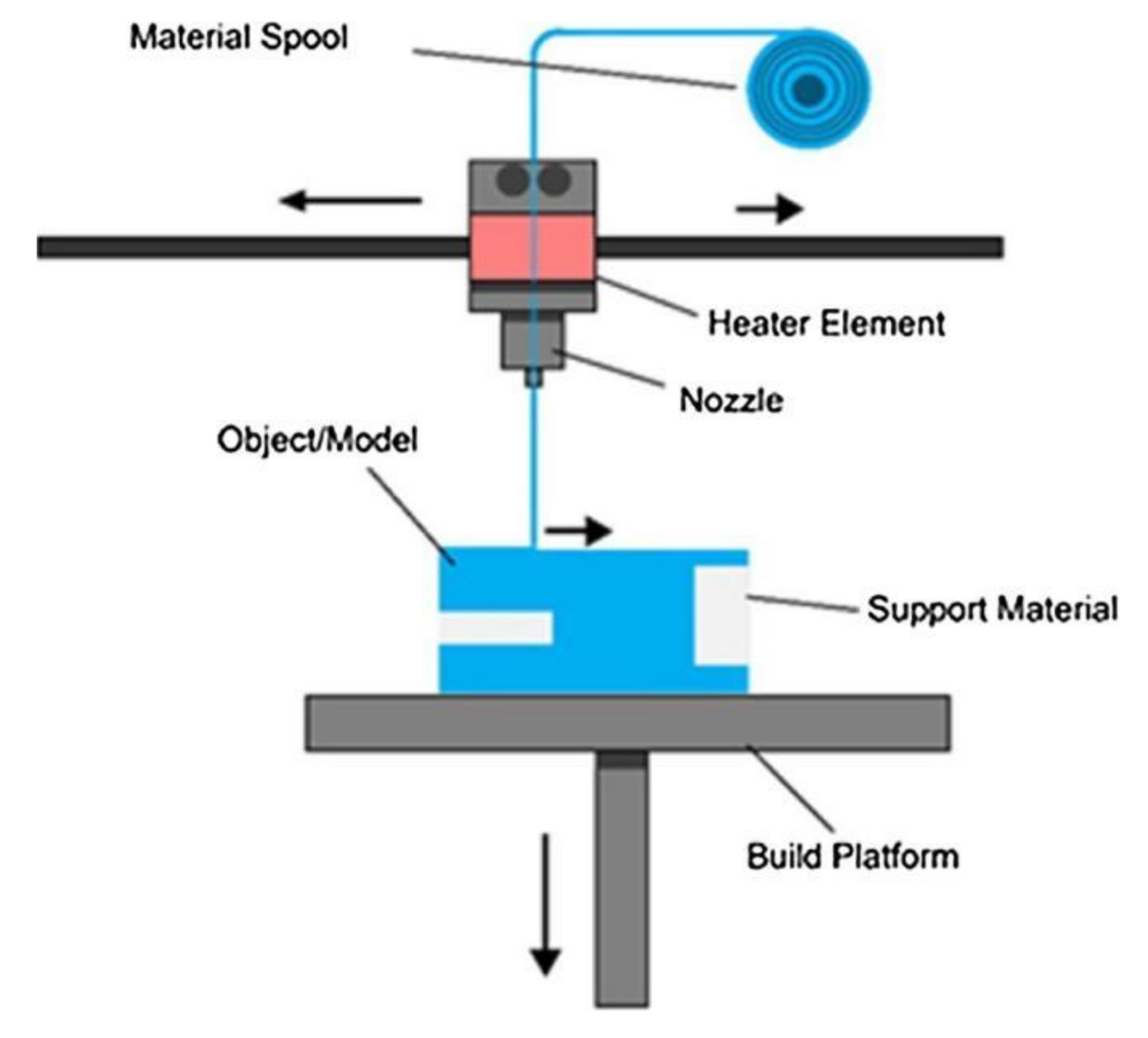
:1. Introduction
2. Adjustments of the Printing Parameters Used in FFF
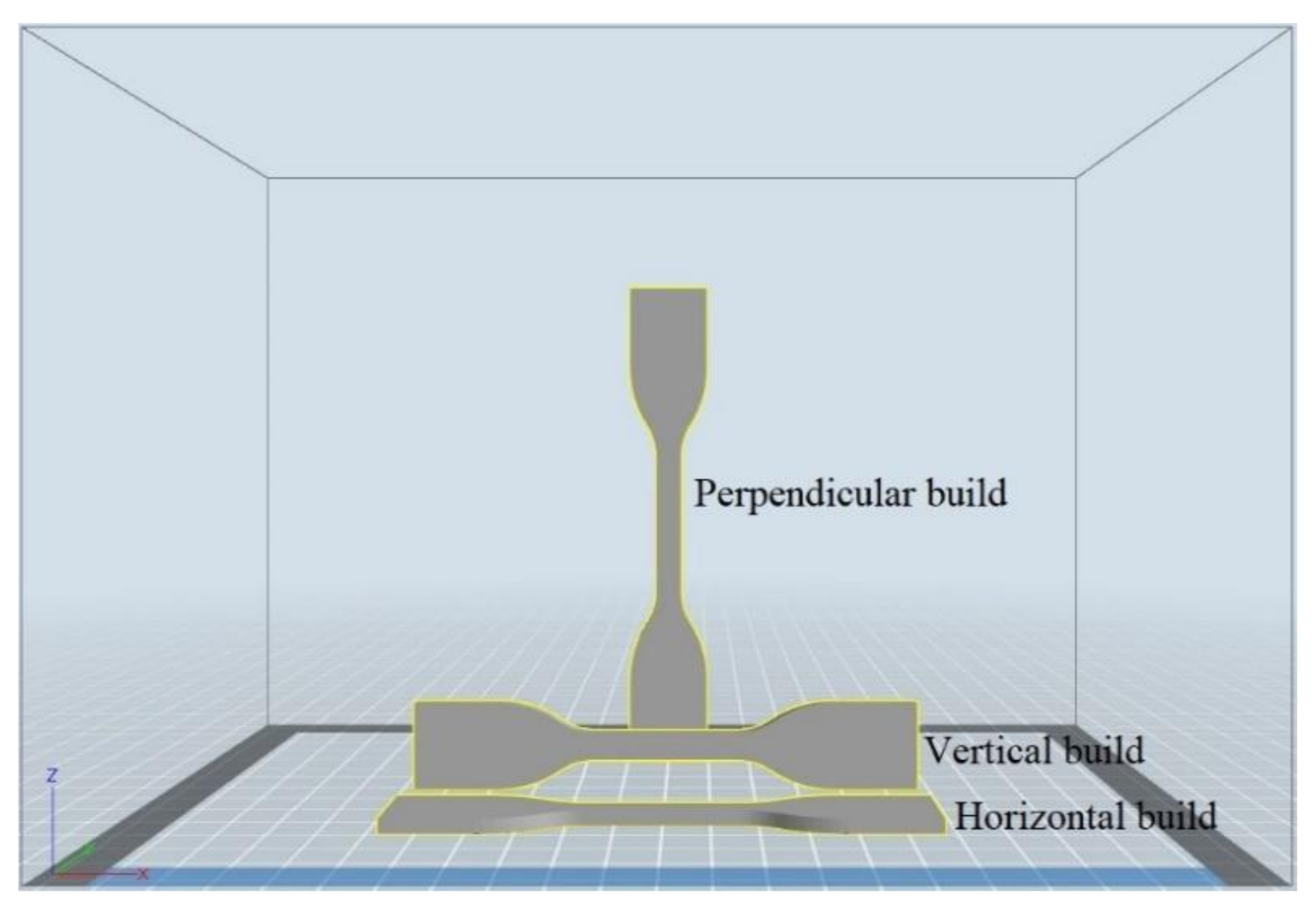
- Horizontal or xyz build, where the nozzle moves along the x-axis that represents the length, the y-axis that represents the width, and the z-axis that represents the thickness of the printed parts;
- Vertical or xzy build, where the nozzle moves along the x-axis that represents the length, the z-axis that represents the width, and the y-axis that represents the thickness of the printed parts;
- Perpendicular or zxy build, where the nozzle moves along the z-axis that represents the length, the x-axis that represents the width, and the y-axis that represents the thickness of the printed parts.
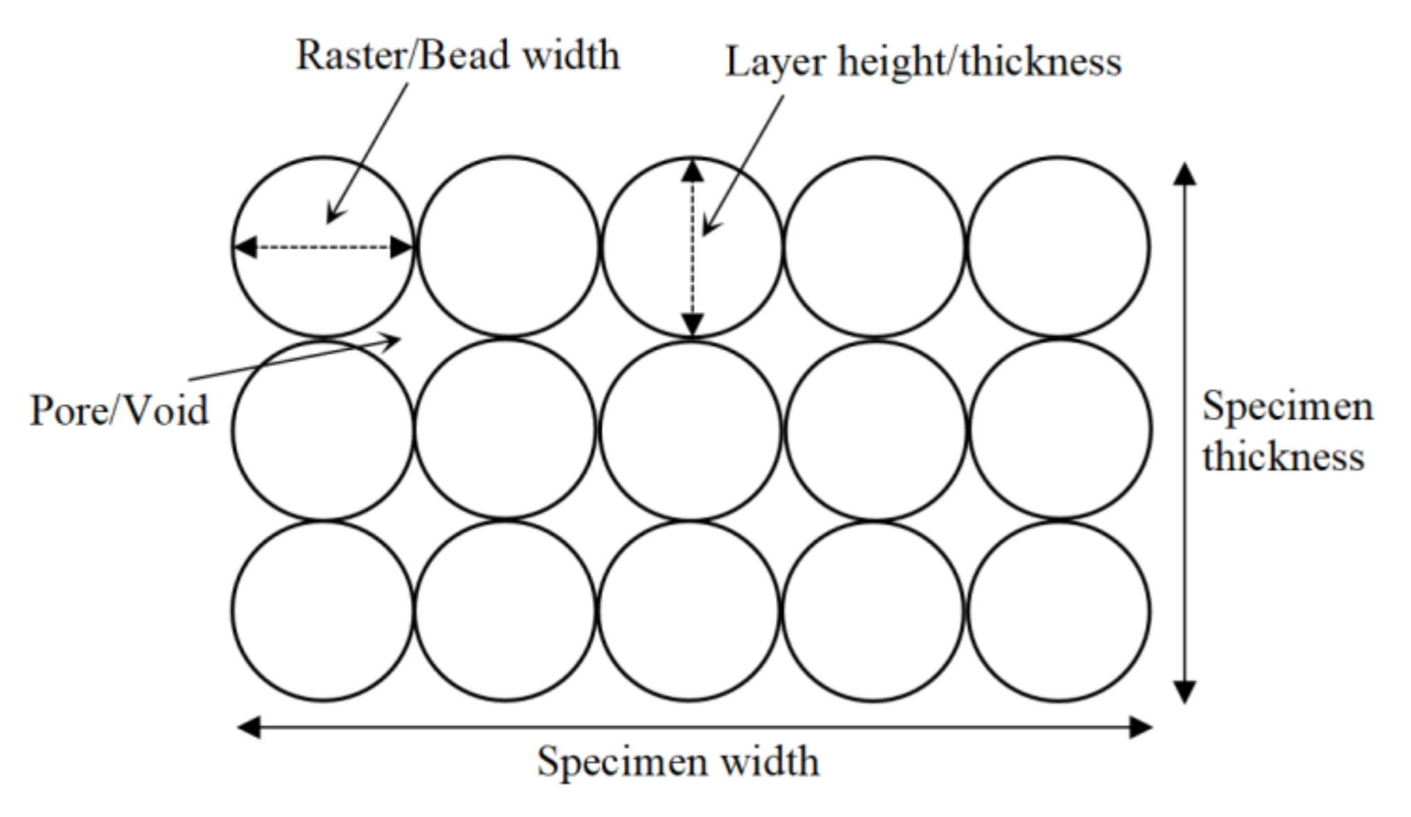
- increasing the raster width;
- increasing the infill overlap percentage and the perimeter overlap percentage.
- using the filling gaps option in the space between the walls.
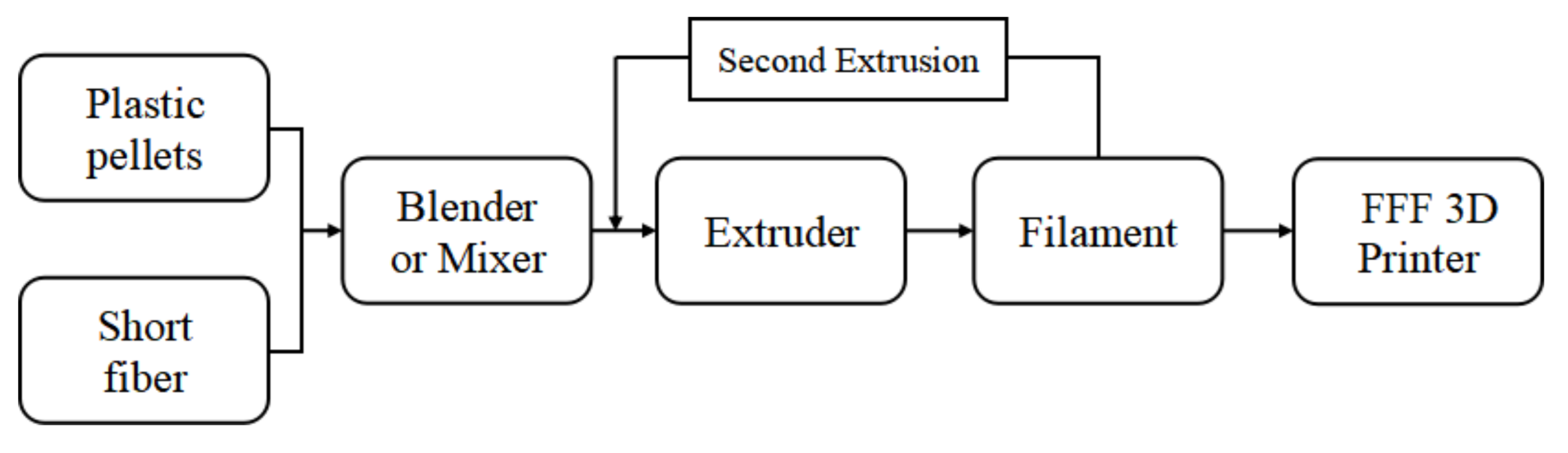
3. Short Fiber Reinforcement (SFR) Method
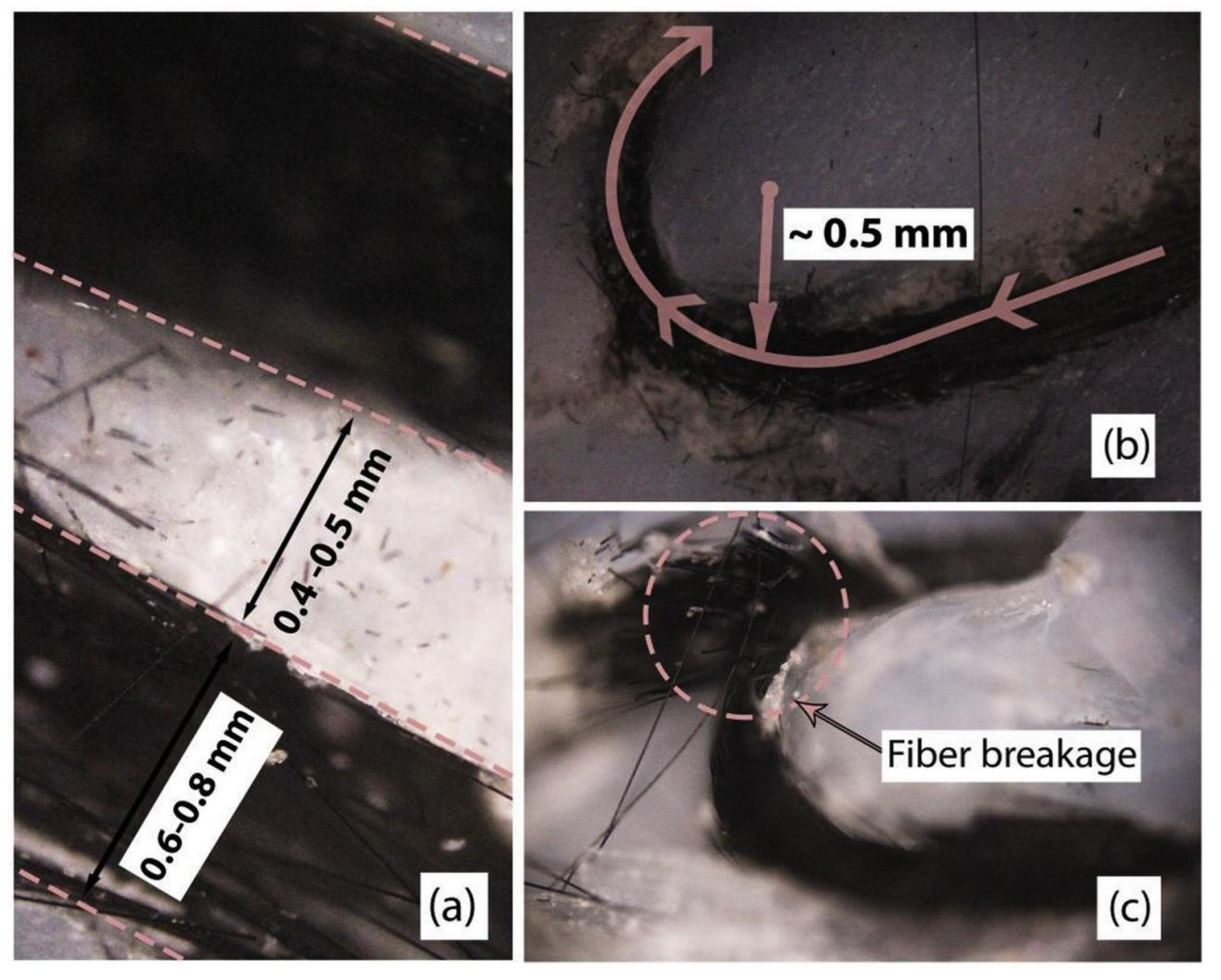
4. Continuous Fiber Reinforcement (CFR) Method
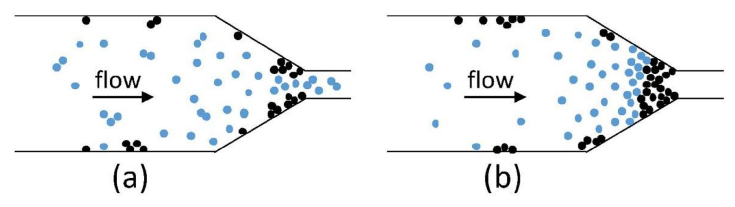
5. Powder Addition Reinforcement (PAR) Method
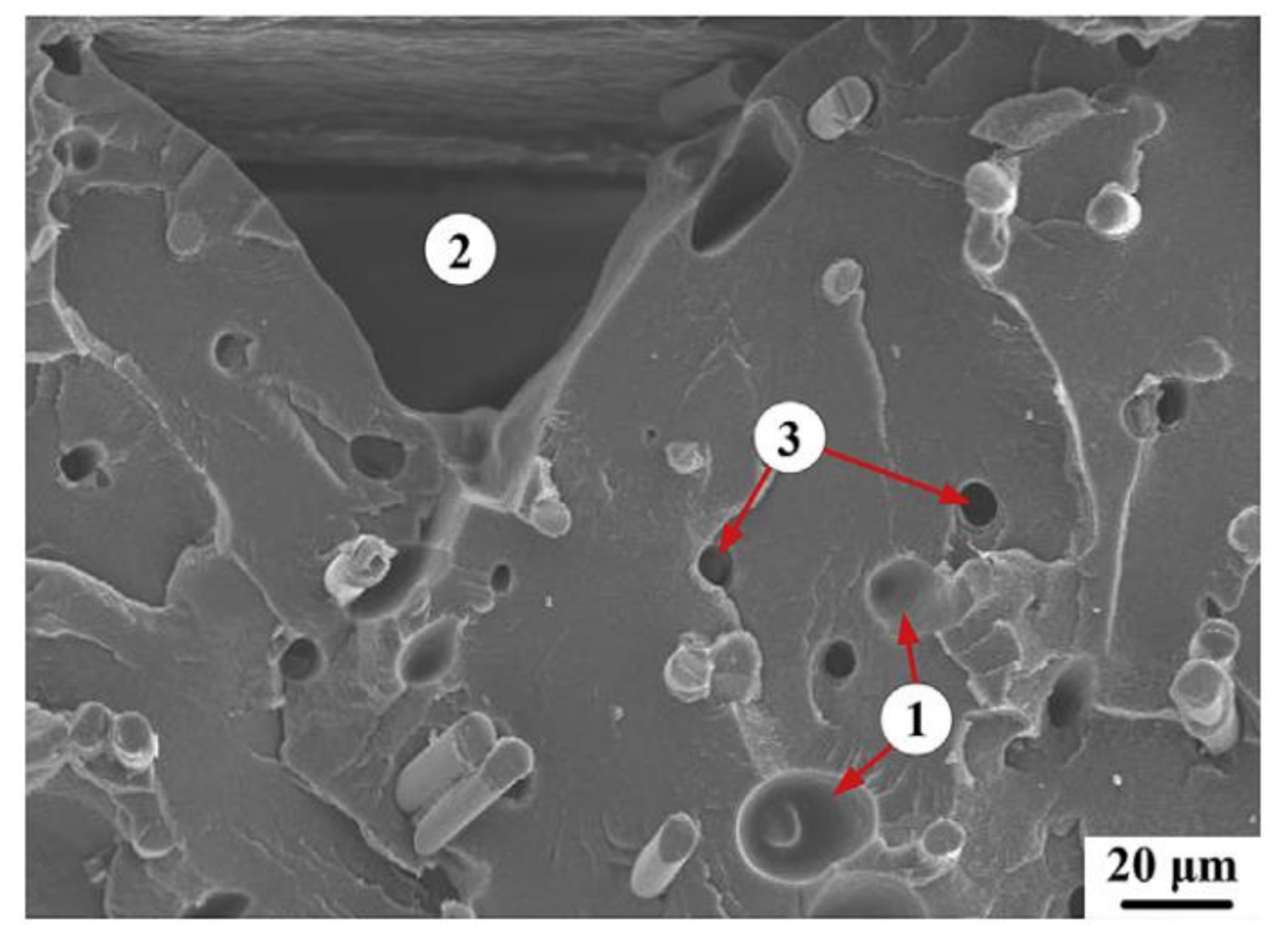
- gas-evoluted pores that form during the extrusion process of the blend filament;
- physical gaps that form at the inter-raster region of the printed materials;
- holes that form around the pulled-out fibers, existing on the fracture interface of the printed parts.
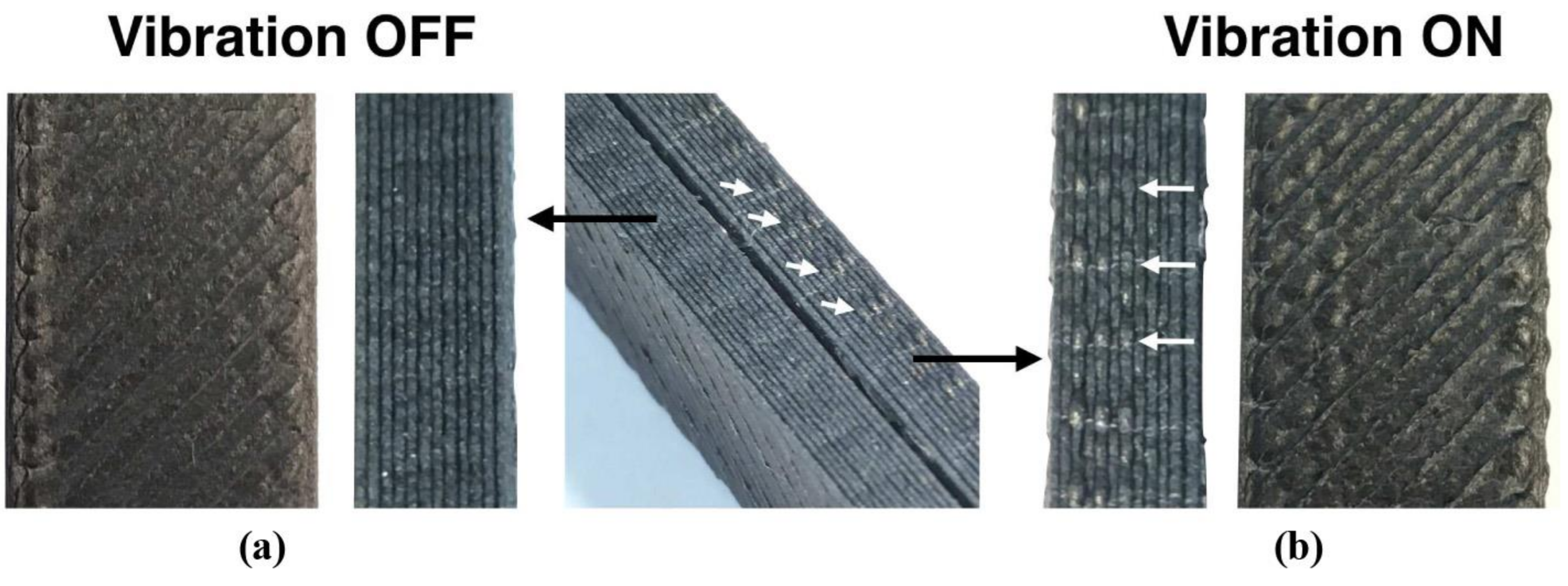
6. Vibration-Assisted FFF (VA-FFF) Method
7. Annealing Post-Processing
8. Concluding Remarks
Author Contributions
Funding
Institutional Review Board Statement
Informed Consent Statement
Conflicts of Interest
References
- Huang, S.H.; Liu, P.; Mokasdar, A.; Hou, L. Additive manufacturing and its societal impact: A literature review. Int. J. Adv. Manuf. Technol. 2013, 67, 1191–1203. [Google Scholar] [CrossRef]
- Stansbury, J.W.; Idacavage, M.J. 3D printing with polymers: Challenges among expanding options and opportunities. Dent. Mater. 2016, 32, 54–64. [Google Scholar] [CrossRef]
- Pedersen, D.B. Additive Manufacturing: Multi Material Processing and Part Quality Control; Technical University of Denmark: Kgs. Lyngby, Denmark, 2013. [Google Scholar]
- Gurr, M.; Mülhaupt, R. Rapid Prototyping. In Polymer Science: A Comprehensive Reference; Elsevier: Amsterdam, The Netherlands, 2012; Volume 8, pp. 77–99. ISBN 9780444533494. [Google Scholar]
- Kruth, J.; Mercelis, P.; Van Vaerenbergh, J.; Froyen, L.; Rombouts, M. Binding mechanisms in selective laser sintering and selective laser melting. Rapid Prototyp. J. 2005, 11, 26–36. [Google Scholar] [CrossRef] [Green Version]
- Mueller, B.; Kochan, D. Laminated object manufacturing for rapid tooling and patternmaking in foundry industry. Comput. Ind. 1999, 39, 47–53. [Google Scholar] [CrossRef]
- Too, M.; Leong, K.; Chua, C.; Du, Z.; Yang, S.; Cheah, C.; Ho, S. Investigation of 3D Non-Random Porous Structures by Fused Deposition Modelling. Int. J. Adv. Manuf. Technol. 2002, 19, 217–223. [Google Scholar] [CrossRef]
- Kruth, J.-P.; Leu, M.; Nakagawa, T. Progress in Additive Manufacturing and Rapid Prototyping. CIRP Ann. 1998, 47, 525–540. [Google Scholar] [CrossRef]
- Chua, C.K.; Leong, K.F.; An, J. Introduction to rapid prototyping of biomaterials. In Rapid Prototyping of Biomaterials; Elsevier: Amsterdam, The Netherlands, 2014; pp. 1–15. ISBN 9780857095992. [Google Scholar]
- Dawoud, M.; Taha, I.; Ebeid, S.J. Mechanical behaviour of ABS: An experimental study using FDM and injection moulding techniques. J. Manuf. Process. 2016, 21, 39–45. [Google Scholar] [CrossRef]
- Sayanjali, M.; Rezadoust, A.M.; Sourki, F.A. Tailoring physico-mechanical properties and rheological behavior of ABS filaments for FDM via blending with SEBS TPE. Rapid Prototyp. J. 2020, 26, 1687–1700. [Google Scholar] [CrossRef]
- Dizon, J.R.C.; Espera, A.H.; Chen, Q.; Advincula, R.C. Mechanical characterization of 3D-printed polymers. Addit. Manuf. 2018, 20, 44–67. [Google Scholar] [CrossRef]
- Li, F.; Yu, Z.; Yang, Z. Failure characterization of PLA parts fabricated by fused deposition modeling using acoustic emission. Rapid Prototyp. J. 2020, 26, 1177–1182. [Google Scholar] [CrossRef]
- Guo, N.; Leu, M.C. Additive manufacturing: Technology, applications and research needs. Front. Mech. Eng. 2013, 8, 215–243. [Google Scholar] [CrossRef]
- Banga, H.K.; Belokar, R.M.; Kalra, P.; Kumar, R. Fabrication and stress analysis of ankle foot orthosis with additive manufacturing. Rapid Prototyp. J. 2018, 24, 301–312. [Google Scholar] [CrossRef]
- Banga, H.K.; Kalra, P.; Belokar, R.M.; Kumar, R. Customized design and additive manufacturing of kids’ ankle foot orthosis. Rapid Prototyp. J. 2020, 26, 1677–1685. [Google Scholar] [CrossRef]
- Schwartz, J.J.; Hamel, J.; Ekstrom, T.; Ndagang, L.; Boydston, A.J. Not all PLA filaments are created equal: An experimental investigation. Rapid Prototyp. J. 2020, 26, 1263–1276. [Google Scholar] [CrossRef]
- Tekinalp, H.L.; Kunc, V.; Velez-Garcia, G.M.; Duty, C.E.; Love, L.J.; Naskar, A.K.; Blue, C.A.; Ozcan, S. Highly oriented carbon fiber–polymer composites via additive manufacturing. Compos. Sci. Technol. 2014, 105, 144–150. [Google Scholar] [CrossRef] [Green Version]
- Jones, J.B.; Wimpenny, D.I.; Gibbons, G. Additive manufacturing under pressure. Rapid Prototyp. J. 2015, 21, 89–97. [Google Scholar] [CrossRef]
- Dul, S.; Fambri, L.; Pegoretti, A. Fused deposition modelling with ABS-graphene nanocomposites. Compos. Part A Appl. Sci. Manuf. 2016, 85, 181–191. [Google Scholar] [CrossRef]
- Ahn, S.; Montero, M.; Odell, D.; Roundy, S.; Wright, P.K. Anisotropic material properties of fused deposition modeling ABS. Rapid Prototyp. J. 2002, 8, 248–257. [Google Scholar] [CrossRef] [Green Version]
- Averett, R.D.; Realff, M.L.; Jacob, K.I.; Cakmak, M.; Yalcin, B. The mechanical behavior of poly(lactic acid) unreinforced and nanocomposite films subjected to monotonic and fatigue loading conditions. J. Compos. Mater. 2011, 45, 2717–2726. [Google Scholar] [CrossRef]
- Grasso, M.; Azzouz, L.; Ruiz-Hincapie, P.; Zarrelli, M.; Ren, G. Effect of temperature on the mechanical properties of 3D-printed PLA tensile specimens. Rapid Prototyp. J. 2018, 24, 1337–1346. [Google Scholar] [CrossRef] [Green Version]
- Gibson, I.; Rosen, D.; Stucker, B. Additive Manufacturing Technologies; Springer: New York, NY, USA, 2015; Volume 17, ISBN 978-1-4939-2112-6. [Google Scholar]
- Keleş, Ö.; Blevins, C.W.; Bowman, K.J. Effect of build orientation on the mechanical reliability of 3D printed ABS. Rapid Prototyp. J. 2017, 23, 320–328. [Google Scholar] [CrossRef]
- Arifvianto, B.; Wirawan, Y.B.; Salim, U.A.; Suyitno, S.; Mahardika, M. Effects of extruder temperatures and raster orientations on mechanical properties of the FFF-processed polylactic-acid (PLA) material. Rapid Prototyp. J. 2021, 27, 1761–1775. [Google Scholar] [CrossRef]
- Ivey, M.; Melenka, G.W.; Carey, J.P.; Ayranci, C. Characterizing short-fiber-reinforced composites produced using additive manufacturing. Adv. Manuf. Polym. Compos. Sci. 2017, 3, 81–91. [Google Scholar] [CrossRef] [Green Version]
- Ning, F.; Cong, W.; Qiu, J.; Wei, J.; Wang, S. Additive manufacturing of carbon fiber reinforced thermoplastic composites using fused deposition modeling. Compos. Part B Eng. 2015, 80, 369–378. [Google Scholar] [CrossRef]
- Sood, A.K.; Ohdar, R.; Mahapatra, S. Parametric appraisal of mechanical property of fused deposition modelling processed parts. Mater. Des. 2010, 31, 287–295. [Google Scholar] [CrossRef]
- Slonov, A.L.; Khashirov, A.A.; Zhansitov, A.A.; Rzhevskaya, E.V.; Khashirova, S.Y. The influence of the 3D-printing technology on the physical and mechanical properties of polyphenylene sulfone. Rapid Prototyp. J. 2018, 24, 1124–1130. [Google Scholar] [CrossRef]
- Rajpurohit, S.R.; Dave, H.K. Effect of process parameters on tensile strength of FDM printed PLA part. Rapid Prototyp. J. 2018, 24, 1317–1324. [Google Scholar] [CrossRef]
- Mohamed, O.A.; Masood, S.H.; Bhowmik, J.L. Influence of processing parameters on creep and recovery behavior of FDM manufactured part using definitive screening design and ANN. Rapid Prototyp. J. 2017, 23, 998–1010. [Google Scholar] [CrossRef]
- Montero, M.; Roundy, S.; Odell, D. Material characterization of fused deposition modeling (FDM) ABS by designed experiments. In Proceedings of the Rapid Prototyping and Manufacturing Conference, Cincinnati, OH, USA, 14–17 May 2001; pp. 1–21. [Google Scholar]
- Nsengimana, J.; Van Der Walt, J.; Pei, E.; Miah, M. Effect of post-processing on the dimensional accuracy of small plastic additive manufactured parts. Rapid Prototyp. J. 2019, 25, 1–12. [Google Scholar] [CrossRef]
- Shanmugam, V.; Das, O.; Babu, K.; Marimuthu, U.; Veerasimman, A.; Johnson, D.J.; Neisiany, R.E.; Hedenqvist, M.S.; Ramakrishna, S.; Berto, F. Fatigue behaviour of FDM-3D printed polymers, polymeric composites and architected cellular materials. Int. J. Fatigue 2021, 143, 106007. [Google Scholar] [CrossRef]
- Álvarez, K.; Lagos, R.F.; Aizpun, M. Investigating the influence of infill percentage on the mechanical properties of fused deposition modelled ABS parts. Ing. Investig. 2016, 36, 110. [Google Scholar] [CrossRef] [Green Version]
- Es-Said, O.S.; Foyos, J.; Noorani, R.; Mendelson, M.; Marloth, R.; Pregger, B.A. Effect of Layer Orientation on Mechanical Properties of Rapid Prototyped Samples. Mater. Manuf. Process. 2000, 15, 107–122. [Google Scholar] [CrossRef]
- Rodríguez, J.F.; Thomas, J.P.; Renaud, J.E. Mechanical behavior of acrylonitrile butadiene styrene (ABS) fused deposition materials. Experimental investigation. Rapid Prototyp. J. 2001, 7, 148–158. [Google Scholar] [CrossRef]
- Bellini, A.; Güçeri, S. Mechanical characterization of parts fabricated using fused deposition modeling. Rapid Prototyp. J. 2003, 9, 252–264. [Google Scholar] [CrossRef]
- Lee, C.; Kim, S.; Kim, H.; Ahn, S. Measurement of anisotropic compressive strength of rapid prototyping parts. J. Mater. Process. Technol. 2007, 187–188, 627–630. [Google Scholar] [CrossRef]
- Sood, A.K.; Ohdar, R.K.; Mahapatra, S.S. Experimental investigation and empirical modelling of FDM process for compressive strength improvement. J. Adv. Res. 2012, 3, 81–90. [Google Scholar] [CrossRef] [Green Version]
- Jami, H.; Masood, S.H.; Song, W. Dynamic Response of FDM Made ABS Parts in Different Part Orientations. Adv. Mater. Res. 2013, 748, 291–294. [Google Scholar] [CrossRef]
- Durgun, I.; Ertan, R. Experimental investigation of FDM process for improvement of mechanical properties and production cost. Rapid Prototyp. J. 2014, 20, 228–235. [Google Scholar] [CrossRef]
- Pei, E.; Lanzotti, A.; Grasso, M.; Staiano, G.; Martorelli, M. The impact of process parameters on mechanical properties of parts fabricated in PLA with an open-source 3-D printer. Rapid Prototyp. J. 2015, 21, 604–617. [Google Scholar] [CrossRef] [Green Version]
- Ziemian, S.; Okwara, M.; Ziemian, C.W. Tensile and fatigue behavior of layered acrylonitrile butadiene styrene. Rapid Prototyp. J. 2015, 21, 270–278. [Google Scholar] [CrossRef]
- Rankouhi, B.; Javadpour, S.; Delfanian, F.; Letcher, T. Failure Analysis and Mechanical Characterization of 3D Printed ABS with Respect to Layer Thickness and Orientation. J. Fail. Anal. Prev. 2016, 16, 467–481. [Google Scholar] [CrossRef]
- Cantrell, J.T.; Rohde, S.; Damiani, D.; Gurnani, R.; DiSandro, L.; Anton, J.; Young, A.; Jerez, A.; Steinbach, D.; Kroese, C.; et al. Experimental characterization of the mechanical properties of 3D-printed ABS and polycarbonate parts. Rapid Prototyp. J. 2017, 23, 811–824. [Google Scholar] [CrossRef]
- Chacón, J.M.; Caminero, M.A.; García-Plaza, E.; Núñez, P.J. Additive manufacturing of PLA structures using fused deposition modelling: Effect of process parameters on mechanical properties and their optimal selection. Mater. Des. 2017, 124, 143–157. [Google Scholar] [CrossRef]
- Kuznetsov, V.E.; Solonin, A.N.; Tavitov, A.; Urzhumtsev, O.; Vakulik, A. Increasing strength of FFF three-dimensional printed parts by influencing on temperature-related parameters of the process. Rapid Prototyp. J. 2020, 26, 107–121. [Google Scholar] [CrossRef]
- Singh, R.; Singh, S.; Mankotia, K. Development of ABS based wire as feedstock filament of FDM for industrial applications. Rapid Prototyp. J. 2016, 22, 300–310. [Google Scholar] [CrossRef]
- Perez, A.R.T.; Roberson, D.A.; Wicker, R.B. Fracture Surface Analysis of 3D-Printed Tensile Specimens of Novel ABS-Based Materials. J. Fail. Anal. Prev. 2014, 14, 343–353. [Google Scholar] [CrossRef]
- Karsli, N.G.; Yilmaz, T.; Aytac, A.; Ozkoc, G. Investigation of erosive wear behavior and physical properties of SGF and/or calcite reinforced ABS/PA6 composites. Compos. Part B Eng. 2013, 44, 385–393. [Google Scholar] [CrossRef]
- Carneiro, O.S.; Silva, A.F.; Gomes, R. Fused deposition modeling with polypropylene. Mater. Des. 2015, 83, 768–776. [Google Scholar] [CrossRef]
- Halápi, D.; Kovács, S.E.; Bodnár, Z.; Palotás, Á.B.; Varga, L. Tensile analysis of 3D printer filaments. Mater. Sci. Eng. 2019, 44, 14–23. [Google Scholar]
- Qiao, J.; Li, Y.; Li, L. Ultrasound-assisted 3D printing of continuous fiber-reinforced thermoplastic (FRTP) composites. Addit. Manuf. 2019, 30, 100926. [Google Scholar] [CrossRef]
- Ye, W.; Lin, G.; Wu, W.; Geng, P.; Hu, X.; Gao, Z.; Zhao, J. Separated 3D printing of continuous carbon fiber reinforced thermoplastic polyimide. Compos. Part A Appl. Sci. Manuf. 2019, 121, 457–464. [Google Scholar] [CrossRef]
- Li, N.; Li, Y.; Liu, S. Rapid prototyping of continuous carbon fiber reinforced polylactic acid composites by 3D printing. J. Mater. Process. Technol. 2016, 238, 218–225. [Google Scholar] [CrossRef]
- Caminero, M.A.; Chacón, J.M.; García-Moreno, I.; Reverte, J.M. Interlaminar bonding performance of 3D printed continuous fibre reinforced thermoplastic composites using fused deposition modelling. Polym. Test. 2018, 68, 415–423. [Google Scholar] [CrossRef]
- Heidari-Rarani, M.; Rafiee-Afarani, M.; Zahedi, A. Mechanical characterization of FDM 3D printing of continuous carbon fiber reinforced PLA composites. Compos. Part B Eng. 2019, 175, 107147. [Google Scholar] [CrossRef]
- Tian, X.; Liu, T.; Yang, C.; Wang, Q.; Li, D. Interface and performance of 3D printed continuous carbon fiber reinforced PLA composites. Compos. Part A Appl. Sci. Manuf. 2016, 88, 198–205. [Google Scholar] [CrossRef]
- Le Duigou, A.; Barbé, A.; Guillou, E.; Castro, M. 3D printing of continuous flax fibre reinforced biocomposites for structural applications. Mater. Des. 2019, 180, 107884. [Google Scholar] [CrossRef]
- Dickson, A.N.; Barry, J.N.; McDonnell, K.A.; Dowling, D.P. Fabrication of continuous carbon, glass and Kevlar fibre reinforced polymer composites using additive manufacturing. Addit. Manuf. 2017, 16, 146–152. [Google Scholar] [CrossRef]
- Matsuzaki, R.; Ueda, M.; Namiki, M.; Jeong, T.-K.; Asahara, H.; Horiguchi, K.; Nakamura, T.; Todoroki, A.; Hirano, Y. Three-dimensional printing of continuous-fiber composites by in-nozzle impregnation. Sci. Rep. 2016, 6, 23058. [Google Scholar] [CrossRef]
- Li, H.; Wang, T.; Joshi, S.; Yu, Z. The quantitative analysis of tensile strength of additively manufactured continuous carbon fiber reinforced polylactic acid (PLA). Rapid Prototyp. J. 2019, 25, 1624–1636. [Google Scholar] [CrossRef]
- Mangat, A.S.; Singh, S.; Gupta, M.; Sharma, R. Experimental investigations on natural fiber embedded additive manufacturing-based biodegradable structures for biomedical applications. Rapid Prototyp. J. 2018, 24, 1221–1234. [Google Scholar] [CrossRef]
- Naranjo-Lozada, J.; Ahuett-Garza, H.; Castañón, P.O.; Verbeeten, W.M.; Sáiz-González, D. Tensile properties and failure behavior of chopped and continuous carbon fiber composites produced by additive manufacturing. Addit. Manuf. 2019, 26, 227–241. [Google Scholar] [CrossRef]
- Çantı, E.; Aydın, M. Effects of micro particle reinforcement on mechanical properties of 3D printed parts. Rapid Prototyp. J. 2018, 24, 171–176. [Google Scholar] [CrossRef]
- Masood, S.; Song, W. Development of new metal/polymer materials for rapid tooling using Fused deposition modelling. Mater. Des. 2004, 25, 587–594. [Google Scholar] [CrossRef]
- Nikzad, M.; Masood, S.; Sbarski, I. Thermo-mechanical properties of a highly filled polymeric composites for Fused Deposition Modeling. Mater. Des. 2011, 32, 3448–3456. [Google Scholar] [CrossRef]
- Walker, J.S.; Arnold, J.; Shrestha, C.; Smith, D. Antibacterial silver submicron wire-polylactic acid composites for fused filament fabrication. Rapid Prototyp. J. 2020, 26, 32–38. [Google Scholar] [CrossRef]
- Weng, Z.; Wang, J.; Senthil, T.; Wu, L. Mechanical and thermal properties of ABS/montmorillonite nanocomposites for fused deposition modeling 3D printing. Mater. Des. 2016, 102, 276–283. [Google Scholar] [CrossRef]
- Osman, M.A.; Atia, M.R. Investigation of ABS-rice straw composite feedstock filament for FDM. Rapid Prototyp. J. 2018, 24, 1067–1075. [Google Scholar] [CrossRef]
- Ecker, J.V.; Haider, A.; Burzic, I.; Huber, A.; Eder, G.; Hild, S. Mechanical properties and water absorption behaviour of PLA and PLA/wood composites prepared by 3D printing and injection moulding. Rapid Prototyp. J. 2019, 25, 672–678. [Google Scholar] [CrossRef]
- Sezer, H.K.; Eren, O. FDM 3D printing of MWCNT re-inforced ABS nano-composite parts with enhanced mechanical and electrical properties. J. Manuf. Process. 2019, 37, 339–347. [Google Scholar] [CrossRef]
- Beran, T.; Mulholland, T.; Henning, F.; Rudolph, N.; Osswald, T.A. Nozzle clogging factors during fused filament fabrication of spherical particle filled polymers. Addit. Manuf. 2018, 23, 206–214. [Google Scholar] [CrossRef]
- Keleş, Ö.; Anderson, E.H.; Huynh, J. Mechanical reliability of short carbon fiber reinforced ABS produced via vibration assisted fused deposition modeling. Rapid Prototyp. J. 2018, 24, 1572–1578. [Google Scholar] [CrossRef]
- Jiang, S.; Siyajeu, Y.; Shi, Y.; Zhu, S.; Li, H. Improving the forming quality of fused filament fabrication parts by applied vibration. Rapid Prototyp. J. 2020, 26, 202–212. [Google Scholar] [CrossRef]
- Ke, T.; Sun, X. Melting behavior and crystallization kinetics of starch and poly(lactic acid) composites. J. Appl. Polym. Sci. 2003, 89, 1203–1210. [Google Scholar] [CrossRef]
- Sun, Q.; Rizvi, G.M.; Bellehumeur, C.T.; Gu, P. Effect of processing conditions on the bonding quality of FDM polymer filaments. Rapid Prototyp. J. 2008, 14, 72–80. [Google Scholar] [CrossRef]
- Waqar, S.; Liu, J.; Sun, Q.; Guo, K.; Sun, J. Effect of post-heat treatment cooling on microstructure and mechanical properties of selective laser melting manufactured austenitic 316L stainless steel. Rapid Prototyp. J. 2020, 26, 1739–1749. [Google Scholar] [CrossRef]
- Jo, W.; Kwon, O.-C.; Moon, M.-W. Investigation of influence of heat treatment on mechanical strength of FDM printed 3D objects. Rapid Prototyp. J. 2018, 24, 637–644. [Google Scholar] [CrossRef]
- Behzadnasab, M.; Yousefi, A.A.; Ebrahimibagha, D.; Nasiri, F. Effects of processing conditions on mechanical properties of PLA printed parts. Rapid Prototyp. J. 2019, 26, 381–389. [Google Scholar] [CrossRef]


| Authors | Materials | Methods | Dimensions & Testing Standards | Outcomes | |||
|---|---|---|---|---|---|---|---|
| Base | Addition | Tensile | Flexural | Compressive | |||
| Es-Said et al. (2000) [36] | ABS | - | Variation of raster angle | ASTM D638 | ASTM D790 | - | UTS: ~20.6 MPa, at 0° raster angle. FS: ~44.4 MPa, at 0° raster angle. |
| Rodriguez et al. (2001) [37] | ABS | - | Variation of the air gap | ASTM D3039 | - | - | The printed parts had a lower modulus and strength by 11–37% and 2–57%, respectively, compared to the single filament. |
| Ahn et al. (2002) [21] | ABS | - | Variation of raster angles for tensile test; Horizontal & vertical builds for compression, compared to the samples obtained from injection molding (IM) | ASTM D3039 | - | Not standardized | UTS IM: 26 MPa, UTS FFF: 10–3% of IM; The greatest UTS occurred at the sample with a 0° angle. CS IM: ~40 MPa, CS FFF: 80–90% of IM. The greatest CS occurred at the sample with the horizontal build. |
| Bellini and Güçeri (2003) [38] | ABS | - | Variation of build orientations and criss-cross raster angle | ASTM D5937 | - | - | When the tensile load was in-line with the fiber orientation, the tensile strengths of each sample was not much different from one another. If the fiber orientation was not in-line to the tensile load applied, the load bearing role was carried out by the interlayer bonding of adjacent filaments. |
| Lee et al. (2007) [39] | ABS | - | Vertical & horizontal build | - | - | ASTM D695 | CS: 41.26 MPa at a horizontal build—11.6% higher than the CS of the sample prepared with a vertical build. |
| Sood et al. (2010) [29] | ABS | - | Variation of layer thickness, orientation, raster angle, raster width, and air gap | ISO R527 | ISO R178 | - | UTS: ~39.24 MPa, at 0.127 mm layer thickness, 30° orientation, 60° raster angle, 0.4064 mm raster width, and 0.0080 mm air gap. FS: ~18.09 MPa, at 0.127 mm layer thickness, 30° orientation, 60° raster angle, 0.4064 mm raster width, and 0.0080 mm air gap |
| Sood et al. (2012) [40] | ABS | - | Variation of layer thickness, orientation, raster angle, raster width, and air gap | - | - | ISO R291 | CS 17.475 MPa, at 0.254 mm layer thickness, 0.036° orientation, 59.44° raster angle, 0.422 mm raster width, and 0.00026 mm air gap. |
| Jami et al. (2013) [41] | ABS | - | Variation of build orientation on dynamic compressive strength | - | - | Not standardized | Dynamic CS: ~80 MPa, at vertical orientation. |
| Durgun and Ertan (2014) [42] | ABS | - | Variation of build orientation and raster angle (H = Horizontal, V = Vertical, P = Perpendicular) | ISO R527 | ISO R178 | - | UTS: ~35 MPa, at H-0°, but lower modulus (~2 GPa), Elastic Modulus: ~2.5 GPa, at P-90°, but lower strength (~20 MPa). FS: ~60 MPa, at V-0°. |
| Lanzotti et al. (2015) [43] | PLA | - | Variation of build orientation, raster angle, and layer thickness | ASTM D638 | - | - | UTS: 53.59 MPa at 0° raster angle with 0.15 mm layer thickness and horizontal build. |
| Ziemian et al. (2015) [44] | ABS | >- | Variation of raster angle, compared to injection molding (IM) | ASTM D638 | - | - | UTS IM: 27 MPa UTS FFF: 25.15 MPa, at 0° angle. |
| Álvarez et al. (2016) [45] | ABS | - | Variation of infill percentage, build orientation, and extrusion temperature | ASTM D638 | - | - | UTS: 34.57 MPa, at 100% infill, horizontal build, 0.2 mm layer thickness, and 250 °C extrusion orientation, and extrusion temperature. |
| Dawoud et al. (2016) [10] | ABS | - | Variation of criss-cross raster angle and air gap, compared to IM | ISO R527 | ISO R178 | - | UTS IM: 37.7 MPa. UTS FFF: 34.3 MPa, at 45°/−45° raster angle with an air gap of −0.05 mm. FS IM: 72.5 MPa. FS FFF: 64 MPa, at 0°/90° raster angle with an air gap of −0.005 mm. |
| Rankouhi et al. (2016) [46] | ABS | - | Variation of layer thickness, raster angle, and number of layers | ASTM D638 | - | - | UTS: 39.4 MPa, at 0° raster angle, 0.2 mm layer thickness, total 35 layers. The UTS increase as the number of layer increase. |
| Cantrell et al. (2017) [47] | ABS & PC | - | Variation of criss-cross raster angle and build orientation | ASTM D638 | - | - | Yield Strength (ABS): 33.5 ± 0.5 MPa, at 0°/90° horizontal build. Yield Strength (PC): 61.1 ± 0.5 MPa, at 45°/−45° vertical build. |
| Chacón et al. (2017) [48] | PLA | - | Variation of build orientation, layer thickness, and printing speed | ASTM D638 | ASTM D790 | - | UTS: ~88 MPa at horizontal build, 0.06 mm layer thickness, and 80 mm/s printing speed. FS: ~62 MPa at vertical build, 0.06 mm layer thickness, and 80 mm/s printing speed. |
| Rajpurohit and Dave (2018) [31] | PLA | - | Variation of raster angle, layer thickness, and raster width | ASTM D638 | - | - | UTS: 47.3 ± 2.69 MPa at 0° raster angle, 0.1 mm layer height, and 0.6 mm raster width. |
| Kuznetsov et al. (2020) [49] | PLA | - | Variation of extrusion temperature and feed rate | - | Not standardized | - | FS: 71.1 MPa, at 250 °C extrusion temperature, 25 mm/s printing speed, and without cooling from a fan. |
| Authors | Materials | Methods | Dimensions & Testing Standards | Outcomes | |||
|---|---|---|---|---|---|---|---|
| Base | Addition | Tensile | Flexural | Compressive | |||
| Karsli et al. (2013) [52] | ABS | Glass fiber | Fiber content: 5–40 wt% | ISO 527 | - | - | UTS: ~87 MPa at 40 wt% fiber, 117% higher than pure ABS, Elongation decreased from 220 to 10%. |
| Tekinalp et al. (2014) [18] | ABS | Carbon fiber | Fiber content: 10, 20,30, 40 wt% | ASTM D638 | - | - | UTS: 65 MPa at 40 wt% fiber, 85% higher than pure ABS. Tensile modulus 13.7 GPa at 30 wt% fiber, 585% higher than pure ABS. |
| Perez et al. (2014) [51] | ABS | Jute fiber | Fiber content: 5 wt% | ASTM D638 | - | - | UTS: 25.9 MPa, 10% lower than pure ABS, fracture strength increased by 28%. |
| Carneiro et al. (2015) [53] | PP (Polypropylene) | Glass fiber | Fiber content: 30 wt%, with the variation of raster angle | DIN 53504 | - | - | Tensile modulus and strength increased by 30% and 40%, respectively, compared to pure PP. |
| Ning et al. (2015) [28] | ABS | Carbon fiber | Fiber content: 3, 5, 7.5, 10, and 15 wt%, with fiber length 0.1 and 0.15 mm | ASTM D638 | ASTM D790 | - | UTS 42 MPa at 5wt% fiber, 20% higher than pure ABS; Lowest UTS 34 MPa at 10 wt% fiber, 2.85% lower than pure ABS. Young’s modulus 2.5 GPa at 7.5 wt% fiber, 30% higher than pure ABS; ductility decreased as fiber content increased. Flexural strength, flexural modulus, and flexural toughness increased by 11.82%, 16.82%, and 21.86%, respectively, compared to pure ABS, at 5wt% fiber. |
| Dul et al. (2016) [20] | ABS | Graphene (xGnP) | Fiber content: 2, 4, and 8 wt% | ISO 527 | - | - | UTS decreased as xGnP content increased, lowest at UTS with 8 wt% of xGnP, 7% lower than pure ABS. |
| Halápi et al. (2018) [54] | PLA | Glass fiber | Fiber content: 15 wt% | ISO 3167 | - | - | UTS: 45.38 MPa, 2.2% higher than pure PLA. |
| Authors | Materials | Methods | Dimensions & Testing Standards | Outcomes | |||
|---|---|---|---|---|---|---|---|
| Base | Addition | Tensile | Flexural | Compressive | |||
| Li et al. (2016) [57] | PLA | Carbon fiber | Treatment with methylene dichloride solution for both PLA and carbon fiber (Modified CCFR) | Not Standardized | Not Standardized | - | UTS: 91 MPa, 13.75% higher than the material with CCFR (continuous carbon fiber reinforcement), and 225% higher than pure PLA. FS: 156 MPa, 164% higher than the material with CCFR, and 194% higher than pure PLA. |
| Matsuzaki et al. (2016) [63] | PLA | Carbon and Jute fiber | Vol fraction of 6.6% and 6.1% for carbon and jute, respectively | JIS K 7162 for jute. Carbon not standardized | - | - | Carbon > Jute UTS and modulus carbon-reinforced are 185.2 ± 24.6 MPa and 19.5 ± 2.08 GPa, respectively, which are 435% and 599% higher than those of the pure PLA for UTS and modulus, respectively. Failure mode was brittle. |
| Tian et al. (2016) [60] | PLA | Carbon fiber | 1000 fibers in a bundle, variation of printing parameters | - | ISO 14125 | - | The strength and modulus increased with increasing extrusion temperature; the maximum strength and modulus were 155 MPa and 8.6 GPa, respectively, at 240 °C. The strength and modulus decreased with increased layer thickness and hatch spacing. The printing speed did not have a significant effect on strength and modulus. |
| Li et al. (2019) [64] | PLA | Carbon fiber | Variation of fibers content of 1, 3, 5, 7, 10, 15 wt% | National Standard (China) | - | - | UTS increased with increasing fiber content; maximum UTS: 106.3 MPa, 178% higher than pure PLA, at 15 wt% fiber content. |
| Le Duigou et al. (2019) [61] | PLA | Flax fiber | Filament diameter 482 ± 30 μm. Raster angle of 0° and 90° | ISO 527 | - | - | 0° raster angle and 30 vol% fibers had the highest UTS: 253.7 ± 15 MPa, improved by 4.5× in terms of strength and 7× in terms of stiffness compared to pure PLA. |
| Mangat et al. (2018) [65] | PLA | Silk and Sheep Wool | Chemical treatment for silk and sheep wool, final diameter ~11μm. Variations of printing parameters, and fibers insertion sequence | - | ASTM D790 | - | FS: 24.58 MPa, using silk at 100% infill, 0°/90° raster angle, and 4 laminates; 52% lower than pure PLA. |
| Heidari-Rarani et al. (2019) [59] | PLA | Carbon fiber | Carbon fiber diameter 7μm. Chemical treatment for carbon fiber and extruded, the final diameter of the fiber is 1 mm | ASTM D638; ASTM D3039 | ASTM D790 | - | UTS and modulus increased by 36% and 208%, compared to pure PLA; Failure strain decreased by 62%. FS and modulus increased by 109% and 367% compared to pure PLA. |
| Naranjo-Lozada et al. (2019) [66] | Nylon | Carbon fiber | Variation of volume fraction of fiber and fiber placement arrangement | ASTM D638 | - | - | UTS: 304.3 MPa at 54 vol% fiber which was 25× higher than pure nylon and reached an elastic modulus of 23 GPa. The wider arrangement showed slightly better performance than the thinner one. |
| Dickson et al. (2017) [62] | Nylon | Carbon, Glass, and Kevlar fiber | Variation of raster pattern (Concentric and Isotropic); Fiber bundle diameter: 8 μm for carbon, 12 μm for kevlar, and 10 μm for glass | ASTM D3039 | ASTM D790 | - | Carbon > Glass > Kevlar The isotropic pattern was better than the concentric pattern. UTS: 216 MPa with carbon fiber, 254% higher than pure nylon. The failure mode was brittle. FS: 250.23 MPa with carbon fiber, 496% higher than pure nylon. As the fiber volume increased, both tensile and flexural strengths also increased. |
| Authors | Materials | Methods | Dimensions & Testing Standards | Outcomes | |||
|---|---|---|---|---|---|---|---|
| Base | Addition | Tensile | Flexural | Compressive | |||
| Masood and Song (2004) [68] | Nylon | Fe | Powder content of 40 vol% fine (<30 μm) and coarse (50–80 μm), and 30 vol% coarse. | Filament testing | - | - | Highest UTS, Tensile modulus, and tensile strain at break were 3.87 MPa, 54.52 MPa, and 16.82%, respectively at 30% Fe (Coarse). |
| Nikzad et al. (2011) [69] | ABS | Fe | Powder content of 5, 10, 20, 30, and 40 vol% | Not Standardized | - | - | Iron-filled ABS had characteristics of brittle and hard material with much lower elongation. Tensile strength drops significantly (25%) as a result of the addition of 10 vol% of iron powder |
| Karsli et al. (2013) [52] | ABS/PA6 | CaCo3 | Powder content of 5–30 wt%, | ISO 527 | - | - | UTS increased by 15% with 5 wt% addition of CaCo3 powder and then decreased as the powder content increased. Elongation decreased from 220% to 62% |
| Perez et al. (2014) [51] | ABS | TiO2 | Powder content of 5 wt% | ASTM D638 | - | - | The UTS increased by 12.98% compared to pure ABS, but the strain decreased by 10%. |
| Weng et al. (2016) [71] | ABS | OMMT | Powder content of 1, 3, and 5 wt% | ASTM D638 | ASTM D790 | - | Tensile strength and elastic modulus increased by 43% and 200%, respectively, Flexural strength increased by 33.3%. |
| Osman and Atia (2018) [72] | ABS | RS | Powder content of 5, 10, and 15 wt%, variation of raster angle | ASTM D638 | ASTM D790 | - | UTS decreased as the RS content increased, then increased again until reaching maximum UTS at 15 wt% of RS content at a 0° raster angle. The tensile modulus decreased as the RS content increased. FS decreased as the RS content increased, then increased again until reaching maximum FS at 15 wt% of RS content at a 0° raster angle. The flexural modulus decreased as the RS content increased, and then increased again until reaching a maximum modulus at 15 wt% of RS content at a 0° raster angle. |
| Çanti and Aydin (2018) [67] | ABS | Al & ZrB2 | Powder content of 1.5 wt% | ISO 527 | ASTM D790 | - | UTS increased by 0.3% and 12.6% with the addition of Al and ZrB2, respectively. The strain increased by 85% and 108% with the addition of ZrB2 and Al, respectively. FS decreased around by 5% with the addition of 1.5 wt% Al. FS increased by 8.7% with the addition of ZrB2. The deflection property improved by 3.7 and 26 percent with Al and ZrB2 addition, respectively. |
| Ecker et al. (2019) [73] | PLA | Wood | Powder content of 15 and 30 wt% | ASTM D638 | - | - | UTS decreased as the wood powder content increased, whereas the water absorption increased as the wood powder content increased. |
| Sezer and Eren (2019) [74] | ABS | MWCNT | Powder content of 1, 3, 5, 7, and 10 wt%, variation of raster angle | ASTM D412 | - | - | UTS was remarkably increased by 288% compared to pure ABS at 7 wt% of MWCNT at a 0°/90° criss-cross raster angle. |
| Walker et al. (2020) [70] | PLA | AgSMW (Silver sub-micron) | Powder content of 0.1, 1, and 10 wt% | ASTM D638 | - | - | UTS and strain at break decreased moderately as the AgSMW content increased, whereas the tensile modulus did not chang significantly. However, the addition of 10 wt% of AgSMW significantly reduced bacteria growth by close to 50%. |
| Authors | Materials | Methods | Dimensions & Testing Standards | Outcomes | |||
|---|---|---|---|---|---|---|---|
| Base | Addition | Tensile | Flexural | Compressive | |||
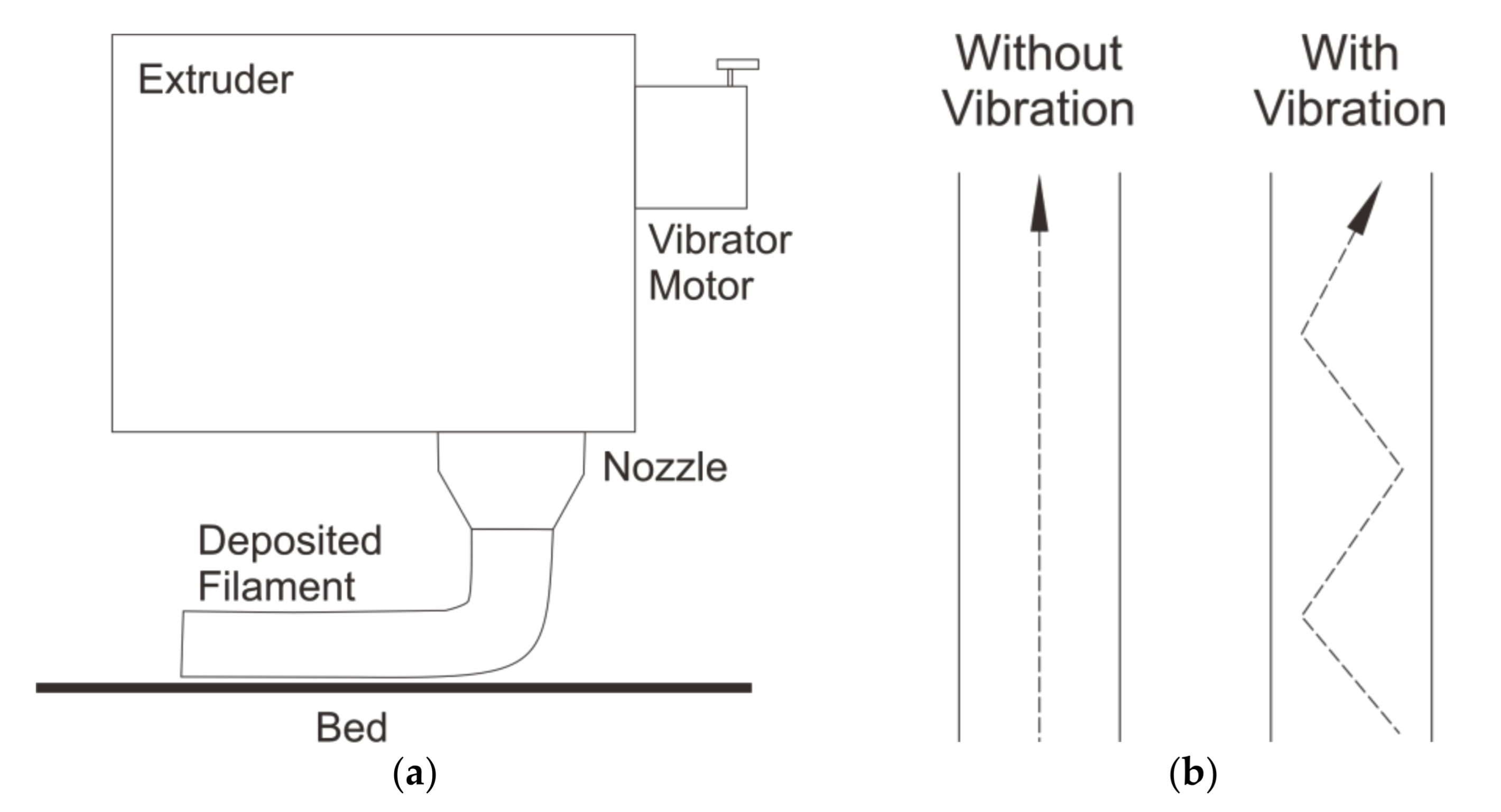
| Keleş et al. (2018) [76] | ABS | Carbon fiber | Vibration on printing head. Amplitude ~0.15 mm, wavelength 4.8 mm at ~375 Hz. | Not Standardized | - | - | Total porosity decreased from 13 to 10 vol%. The fracture strength, tensile strength, and nominal strain-at-break increased by more than 10% compared to non-vibrated specimens. Elastic modulus improved from 2.5 ± 0.1 GPa to 2.7 ± 0.1 GPa. |
| Jiang et al. (2020) [77] | PLA | - | Vibration on printing head. A vertical direction of vibration at 100 Hz, an amplitude of 0.35 g. Variation of build orientation. | ISO 527 | - | - | Tensile strength increased by almost 50% at Z orientation. At X orientation, the tensile strength was not much different to non-vibrated specimens. |
| Authors | Materials | Methods | Dimensions & Testing Standards | Outcomes | |||
|---|---|---|---|---|---|---|---|
| Base | Addition | Tensile | Flexural | Compressive | |||
| Jo et al. (2018) [81] | PLA | - | Variation of annealing time and temperature. Variation of applied pressure. | ASTM D638 | - | - | UTS of specimens that were reheated at 160 °C for 30s increased by 5% compared to non-reheated samples. A combination of a reheating process for 120 s and an applied pressure of 19 N resulted in the improvement of UTS by 10.2% more than the reheating process alone. |
| Behzadna-sab et al. (2019) [82] | PLA | - | Variation of annealing time and temperature. | ISO 527 | - | - | UTS decreased with the increase of annealing temperature or time, with no significant change in the modulus. This is mainly due to the degradation process of PLA molecules. |
| Methods | Advantages | Disadvantages |
|---|---|---|
| Short Fiber Reinforcement (SFR) |
|
|
| Continuous Fiber Reinforcement (CFR) |
|
|
| Powder Addition Reinforcement (PAR) |
|
|
| Vibration-Assisted FFF |
|
|
| Annealing |
|
|
Publisher’s Note: MDPI stays neutral with regard to jurisdictional claims in published maps and institutional affiliations. |
© 2021 by the authors. Licensee MDPI, Basel, Switzerland. This article is an open access article distributed under the terms and conditions of the Creative Commons Attribution (CC BY) license (https://creativecommons.org/licenses/by/4.0/).
Share and Cite
Pratama, J.; Cahyono, S.I.; Suyitno, S.; Muflikhun, M.A.; Salim, U.A.; Mahardika, M.; Arifvianto, B. A Review on Reinforcement Methods for Polymeric Materials Processed Using Fused Filament Fabrication (FFF). Polymers 2021, 13, 4022. https://doi.org/10.3390/polym13224022
Pratama J, Cahyono SI, Suyitno S, Muflikhun MA, Salim UA, Mahardika M, Arifvianto B. A Review on Reinforcement Methods for Polymeric Materials Processed Using Fused Filament Fabrication (FFF). Polymers. 2021; 13(22):4022. https://doi.org/10.3390/polym13224022
Chicago/Turabian StylePratama, Juan, Sukmaji I. Cahyono, Suyitno Suyitno, Muhammad A. Muflikhun, Urip A. Salim, Muslim Mahardika, and Budi Arifvianto. 2021. "A Review on Reinforcement Methods for Polymeric Materials Processed Using Fused Filament Fabrication (FFF)" Polymers 13, no. 22: 4022. https://doi.org/10.3390/polym13224022
APA StylePratama, J., Cahyono, S. I., Suyitno, S., Muflikhun, M. A., Salim, U. A., Mahardika, M., & Arifvianto, B. (2021). A Review on Reinforcement Methods for Polymeric Materials Processed Using Fused Filament Fabrication (FFF). Polymers, 13(22), 4022. https://doi.org/10.3390/polym13224022