Tailoring of Thermo-Mechanical Properties of Hybrid Composite-Metal Bonded Joints


 ,
,  and
and
Abstract
1. Introduction
2. Experimental Approach
2.1. Materials
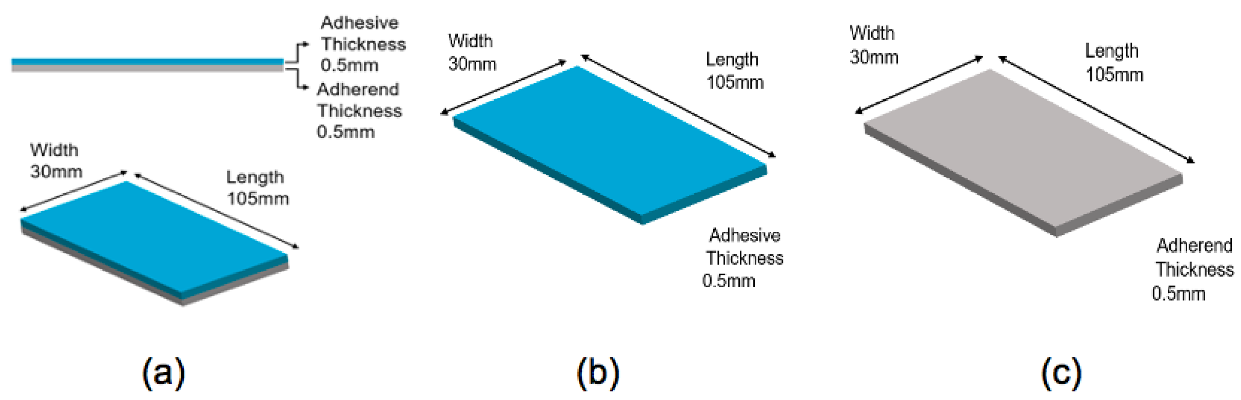
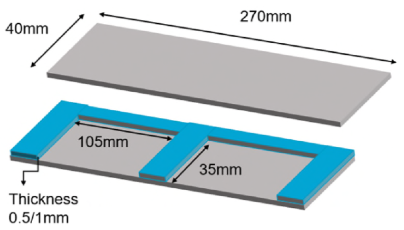
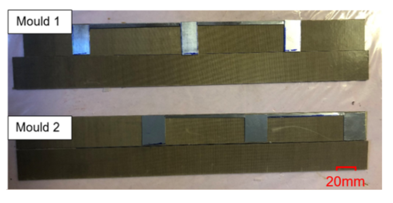
2.2. Preparation and Manufacturing
2.3. Scanning Electron Microscopy
2.4. Raman Spectroscopy
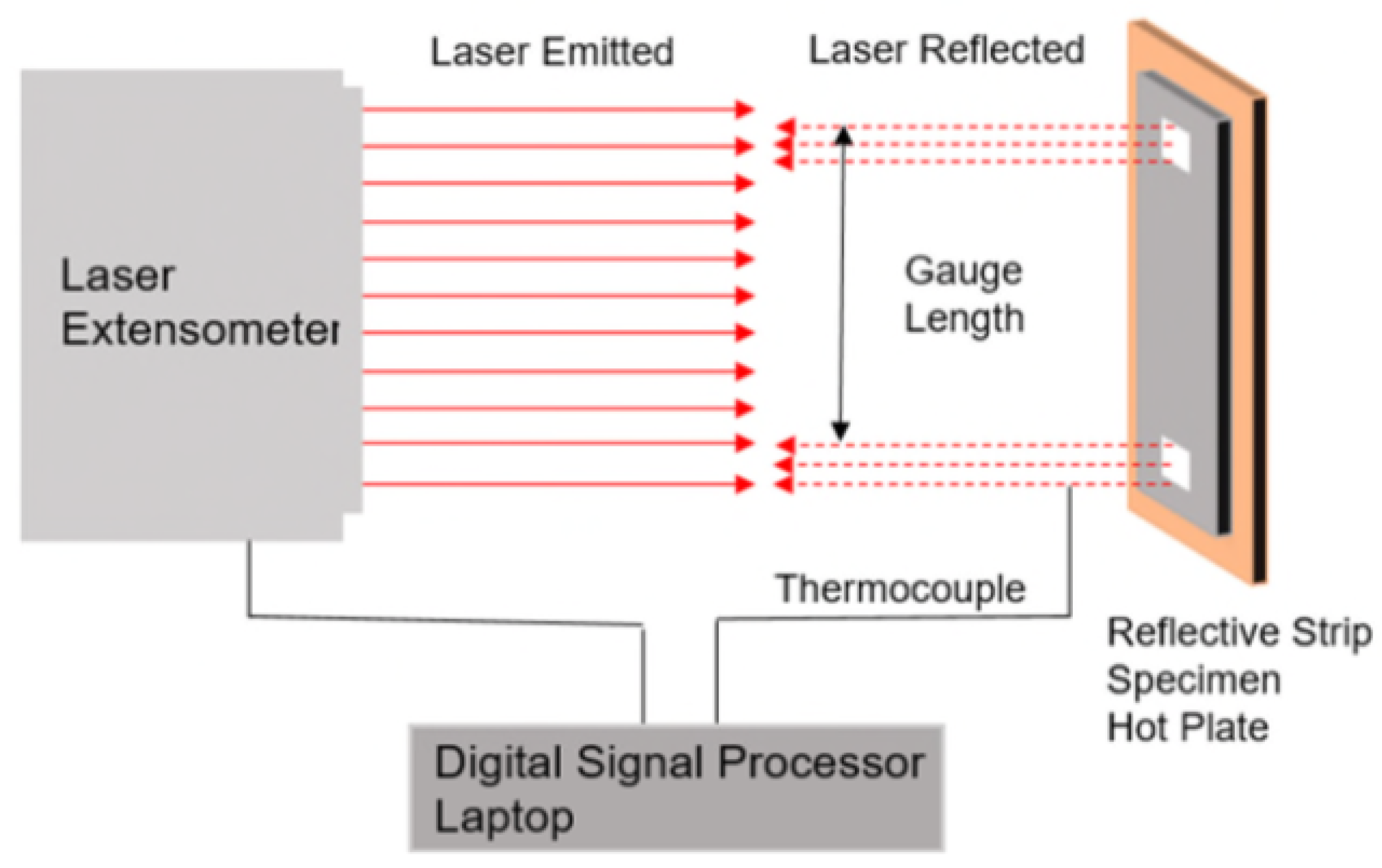
2.5. Thermal Strain Measurement
3. Results
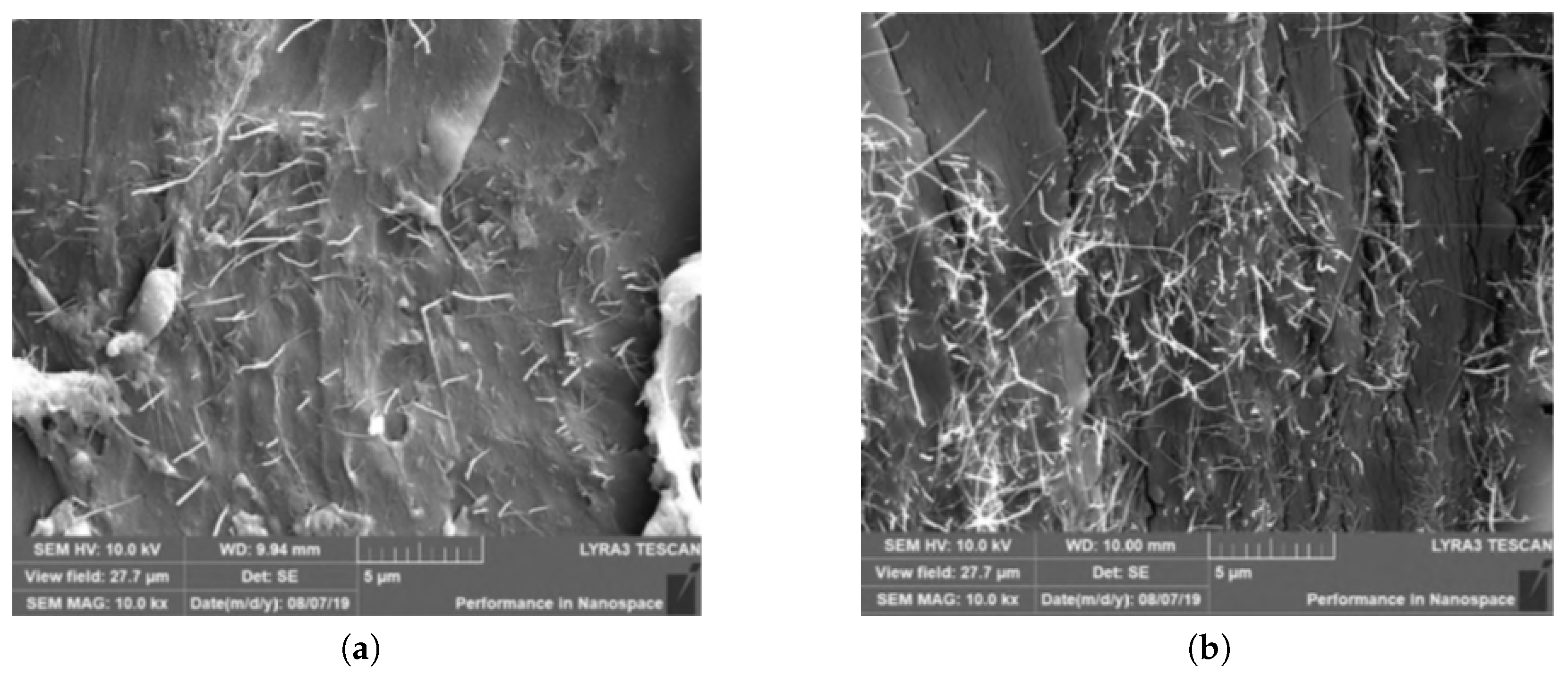
3.1. Fractography
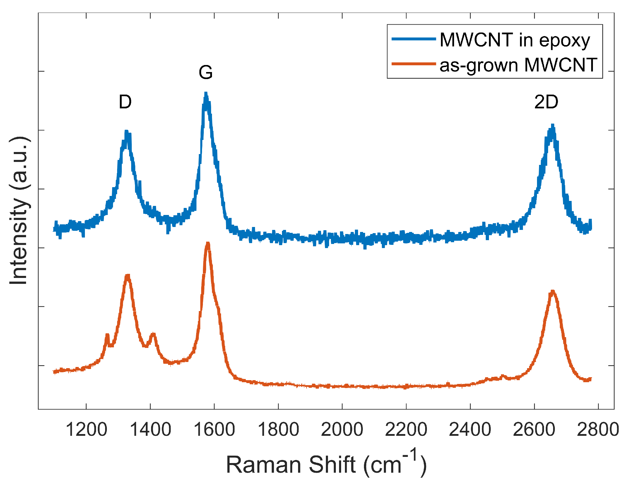
3.2. Raman Spectroscopy
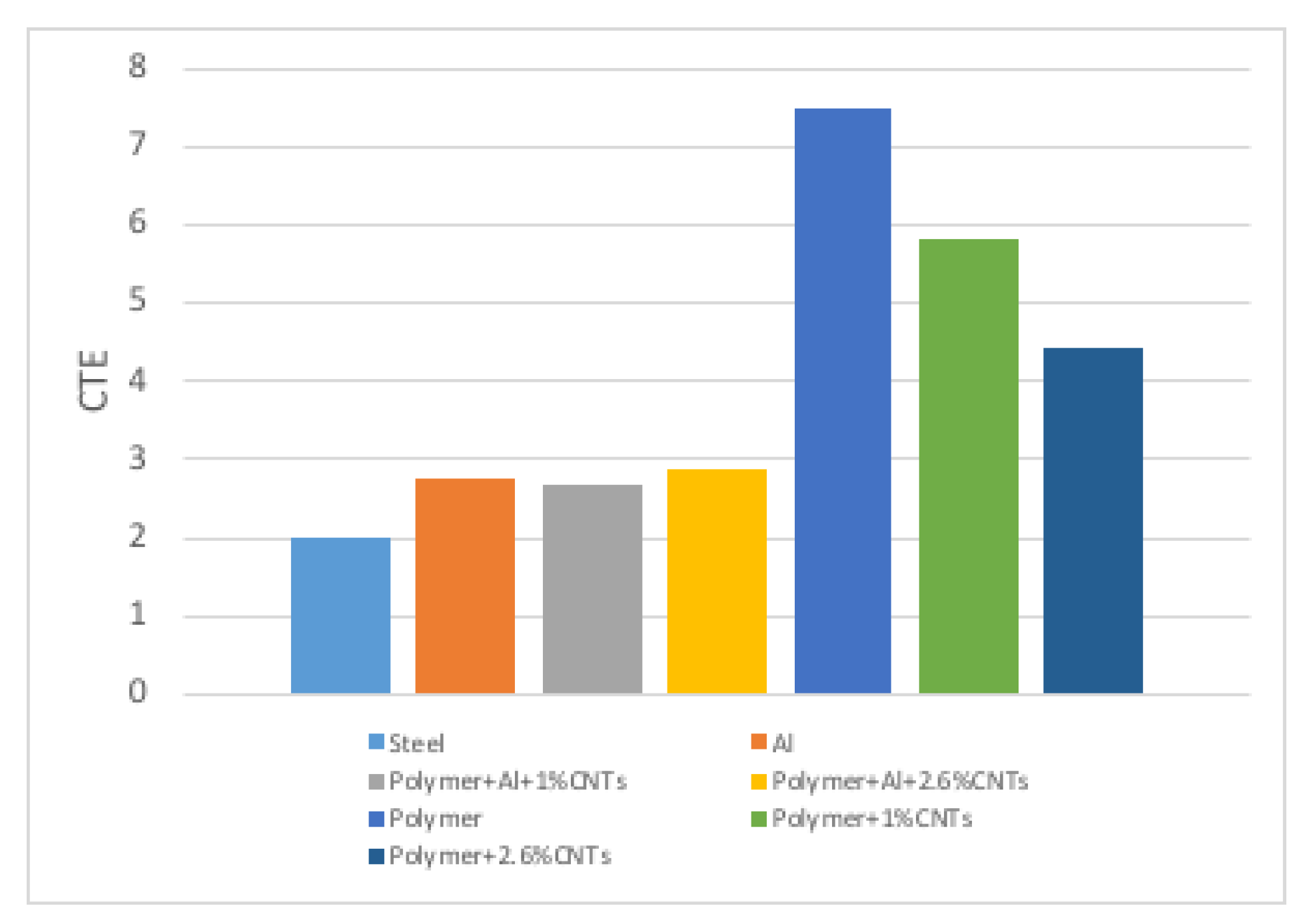
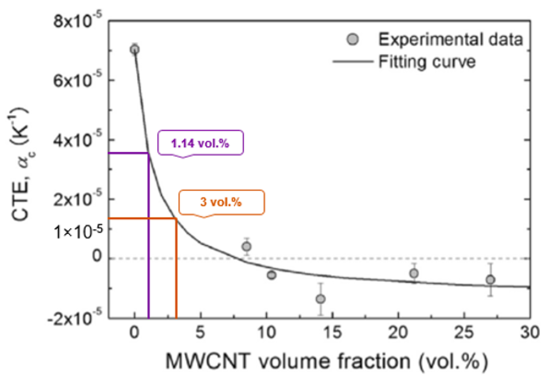
3.3. Coefficient of Thermal Expansion
- Ferrocene was used as the catalyst for the CVD growth of MWCNTs and some catalysts particles might be entrapped within the MWCNTs. As a post-growth purification process was not included in this study, the weight of the catalyst might have been inadvertently included in the weight measurement of MWCNTs. Therefore, the actual weight percentages of the MWCNTs used in the specimens were most likely less than the measured weight percentages. The contribution of catalyst to the CTE of polymer is expected to be negligible [28].
- There was a deviation in the density of MWCNTs used in the calculation to obtain volume fraction, as there was no effective method to measure the density of MWCNTs. The density of MWCNTs is related to the dimension of CNTs and the quantity of the walls in CNTs [29]. The diameter of the MWCNTs synthesised in the present study was between 20 and 100 nm. The density of the MWCNTs used in the present study might be underestimated, as the density of MWCNTs varies from 1.5 gm/cm to 2.5 gm/cm [30].
- If the MWCNTs dispersion is unstable, re-agglomeration starts immediately after the dispersion process is stopped. CNT agglomeration induces a negative influence on the performance of polymers [23]. Agglomerates introduce inhomogeneities to the specimen that may lead to localised stress concentration under thermal load, resulting in the formation of initiation sites for failure and acceleration of breakage.
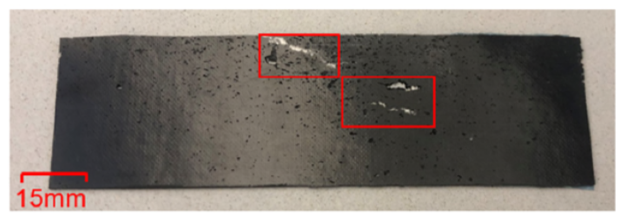
- The defects (porosity, void etc.) in the adhesive part of the specimens may cause poor local bonding between the metal substrate and adhesive, which in turn can result in different thermal expansions of the specimens. In the present study such defects were identified; see Figure 9. Insufficient degassing of the uncured epoxy causes formation of porosity and voids.
4. Conclusions
Author Contributions
Funding
Acknowledgments
Conflicts of Interest
References
- VENEDO (2019) Global EV Sales for 2018. Available online: http://www.ev-volumes.com/country/total-world-plug-in-vehicle-volumes/ (accessed on 1 June 2019).
- Nezhad, H.Y.; Stratakis, D.; Ayre, D.; Addepalli, S.; Zhao, Y. Mechanical performance of composite bonded joints in the presence of localised process-induced zero-thickness defects. Procedia Manuf. 2018, 16, 91–98. [Google Scholar] [CrossRef]
- Liu, Y.; Zhang, X.; Lemanski, S.; Nezhad, H.Y.; Ayre, D. Experimental and numerical study of process-induced defects and their effect on fatigue debonding in composite joints. Int. J. Fatigue 2019, 125, 47–57. [Google Scholar] [CrossRef]
- Nezhad, H.Y.; Zhao, Y.; Liddel, P.D.; Marchante, V.; Roy, R. A novel process-linked assembly failure model for adhesively bonded composite structures. CIRP Ann. 2017, 66, 29–32. [Google Scholar] [CrossRef]
- Nezhad, H.Y.; Egan, B.; Merwick, F.; McCarthy, C.T. Bearing damage characteristics of fibre-reinforced countersunk composite bolted joints subjected to quasi-static shear loading. Compos. Struct. 2017, 166, 184–192. [Google Scholar] [CrossRef]
- Zhou, Y.; Nezhad, H.Y.; Hou, C.; Wan, X.; McCarthy, C.T.; McCarthy, M.A. A three dimensional implicit finite element damage model and its application to single-lap multi-bolt composite joints with variable clearance. Compos. Struct. 2015, 131, 1060–1072. [Google Scholar] [CrossRef]
- Egan, B.; McCarthy, C.T.; McCarthy, M.A.; Gray, P.J.; O’Higgins, R.M. Static and high-rate loading of single and multi-bolt carbon–epoxy aircraft fuselage joints. Compos. Part A Appl. Sci. Manuf. 2013, 53, 97–108. [Google Scholar] [CrossRef]
- Li, L. Research on Static Strength Analysis and Strength Prediction of Adhesively Bonded Single Lap Joint for Autoclave. Int. J. Adhes. Adhes. 2011, 41, 119–126. [Google Scholar]
- GPC Battery. 2015. Available online: http://www.gpcbattery.com/English/index.aspx (accessed on 1 June 2019).
- CBEA. Thermal Management of Electric Vehicle. In SAE Technical Papers; 2019; Available online: https://www.idtechex.com/en/research-report/thermal-management-for-electric-vehicles-2020-2030/715 (accessed on 1 June 2019).
- Shirasu, K.; Yamamoto, G.; Tamaki, I.; Ogasawara, T.; Shimamura, Y.; Inoue, Y.; Hashida, T. Negative axial thermal expansion coefficient of carbon nanotubes: Experimental determination based on measurements of coefficient of thermal expansion for aligned carbon nanotube reinforced epoxy composites. Carbon 2015, 95, 904–909. [Google Scholar] [CrossRef]
- Oh, H.J.; Dao, V.D.; Choi, H.S. Electromagnetic shielding effectiveness of a thin silver layer deposited onto PET film via atmospheric pressure plasma reduction. Appl. Surf. Sci. 2018, 435, 7–15. [Google Scholar] [CrossRef]
- Dao, V.D.; Vu, N.H.; Yun, S. Recent advances and challenges for solar-driven water evaporation system toward applications. Nanoenergy 2020, 68, 104324. [Google Scholar] [CrossRef]
- Dang, H.L.T.; Tran, N.A.; Dao, V.D.; Vu, N.H.; Quang, D.V.; Vu, H.H.T.; Nguyen, T.H.; Pham, T.D.; Hoang, X.C.; Nguyen, H.T.; et al. Carbon nanotubes-ruthenium as an outstanding catalyst for triiodide ions reduction. Synth. Met. 2020, 260, 116299. [Google Scholar] [CrossRef]
- Huntsman (2012), Mechanical Properties: Araldite®LY1564/Aradur®3486/Aradur®3487. Available online: http://www.swiss-composite.ch/pdf/t-Araldite-LY1564-Aradur3486-3487-e.pdf (accessed on 1 March 2019).
- Aria, A.I.; Lyon, B.J.; Gharib, M. Morphology engineering of hollow carbon nanotube pillars by oxygen plasma treatment. Carbon 2015, 81, 376–387. [Google Scholar] [CrossRef]
- Lyon, B.J.; Aria, A.I.; Gharib, M. Fabrication of carbon nanotube—polyimide composite hollow microneedles for transdermal drug delivery. Biomed. Microdevices 2014, 16, 879–886. [Google Scholar] [CrossRef] [PubMed]
- Marcio, L. Carbon Nanotube Reinforced Composites: CNT Polymer Science and Technology; Elsevier: Amsterdam, The Netherlands, 2015. [Google Scholar]
- Bai, Y.; Lin, D.; Wu, F.; Wang, Z.; Xing, B. Adsorption of Triton X-series surfactants and its role in stabilizing multi-walled carbon nanotube suspensions. Chemosphere 2010, 79, 362–367. [Google Scholar] [CrossRef]
- Ikeda, H.; Iwai, M.; Nakajima, D.; Kikuchi, T.; Natsui, S.; Sakaguchi, N.; Suzuki, R.O. Nanostructural characterization of ordered gold particle arrays fabricated via aluminum anodizing, sputter coating, and dewetting. Appl. Surf. Sci. 2019, 465, 747–753. [Google Scholar] [CrossRef]
- Costa, S.; Borowiak-Palen, E.; Kruszyńska, M.; Bachmatiuk, A.; Kaleńczuk, R.J. Characterization of carbon nanotubes by Raman spectroscopy. Mater. Sci. Pol. 2008, 26, 433–441. [Google Scholar]
- Epsilon (2019) MODEL LE-05 and LE-15 Non-Contact Laser Extensometer. Available online: https://www.epsilontech.com/wp-content/uploads/product-specs/Laser-Extensometer.pdf (accessed on 28 April 2019).
- Nezhad, H.Y.; Thakur, V.K. Effect of Morphological Changes due to Increasing Carbon Nanoparticles Content on the Quasi-Static Mechanical Response of Epoxy Resin. Polymers 2018, 10, 1106. [Google Scholar] [CrossRef]
- Rojas, J.A.; Ardila-Rodríguez, L.A.; Diniz, M.F.; Gonçalves, M.; Ribeiro, B.; Rezende, M.C. Optimization of Triton X-100 removal and ultrasound probe parameters in the preparation of multiwalled carbon nanotube buckypaper. Mater. Des. 2019, 166, 107612. [Google Scholar] [CrossRef]
- Aria, A.I.; Gharib, M. Reversible Tuning of the Wettability of Carbon Nanotube Arrays: The Effect of Ultraviolet/Ozone and Vacuum Pyrolysis Treatments. Langmuir 2011, 27, 9005–9011. [Google Scholar] [CrossRef]
- Davis, C.S.; Woodcock, J.; Gilman, J. Preparation of Nanoscale Mutli-walled Carbon Nanotube Dispersions in a Polyetheramine Epoxy for Eco-Toxicological Assessment. Mater. Sci. 2015, 26, 433–441. [Google Scholar]
- Aria, A.I.; Gharib, M. Physicochemical Characteristics and Droplet Impact Dynamics of Superhydrophobic Carbon Nanotube Arrays. Langmuir 2014, 30, 6780–6790. [Google Scholar] [CrossRef] [PubMed]
- Esquenazi, G.L.; Brinson, B.E.; Barron, A. Catalytic Growth of Carbon Nanotubes by Direct Liquid Injection CVD Using the Nanocluster [HxPMo12O40⊂ H4Mo72Fe30(O2CMe)15O254(H2O)98-y(EtOH)y]. Mater. Sci. 2018, 4, 17. [Google Scholar] [CrossRef]
- ELaurent, C.; Flahaut, E.; Peigney, A. The weight and density of carbon nanotubes versus the number of walls and diameter. Carbon 2010, 48, 2994–2996. [Google Scholar] [CrossRef]
- Mazlan, N.B. The Effect of Oxidation Treatment of MWCNT on the Properties of PDMS Nanocomposite. Ph.D. Thesis, Sains Malaysia University, Gelugor, Malaysia, 2012. [Google Scholar]


| Specimen | Constitution | Dimension |
|---|---|---|
| Specimen a | epoxy+Al+1.00 % MWCNTs | 105 mm × 30 mm × 10 mm |
| Specimen b | epoxy+Al+2.68 % MWCNTs | 105 mm × 30 mm × 10 mm |
| Specimen c | epoxy+1.00% MWCNTs | 105 mm × 30 mm × 5 mm |
| Specimen d | epoxy+2.68% MWCNTs | 105 mm × 30 mm × 5 mm |
| Specimen e | Al only | 105 mm × 30 mm × 5 mm |
| Specimen | a | b | c | d | e | Polymer |
|---|---|---|---|---|---|---|
| Length of thermal expansion (mm) | 0.127 | 0.133 | 0.257 | 0.218 | 0.132 | |
| Interval of temperature (°C) | 90 | 90 | 90 | 90 | 90 | |
| CTE °C | 2.66 | 2.87 | 5.87 | 4.43 | 2.75 | 7.5 |
Publisher’s Note: MDPI stays neutral with regard to jurisdictional claims in published maps and institutional affiliations. |
© 2021 by the authors. Licensee MDPI, Basel, Switzerland. This article is an open access article distributed under the terms and conditions of the Creative Commons Attribution (CC BY) license (http://creativecommons.org/licenses/by/4.0/).
Share and Cite
Khaleque, T.; Zhang, X.; Kumar Thakur, V.; Aria, A.I.; Yazdani Nezhad, H. Tailoring of Thermo-Mechanical Properties of Hybrid Composite-Metal Bonded Joints. Polymers 2021, 13, 170. https://doi.org/10.3390/polym13020170
Khaleque T, Zhang X, Kumar Thakur V, Aria AI, Yazdani Nezhad H. Tailoring of Thermo-Mechanical Properties of Hybrid Composite-Metal Bonded Joints. Polymers. 2021; 13(2):170. https://doi.org/10.3390/polym13020170
Chicago/Turabian StyleKhaleque, Tasnuva, Xiaolong Zhang, Vijay Kumar Thakur, Adrianus Indrat Aria, and Hamed Yazdani Nezhad. 2021. "Tailoring of Thermo-Mechanical Properties of Hybrid Composite-Metal Bonded Joints" Polymers 13, no. 2: 170. https://doi.org/10.3390/polym13020170
APA StyleKhaleque, T., Zhang, X., Kumar Thakur, V., Aria, A. I., & Yazdani Nezhad, H. (2021). Tailoring of Thermo-Mechanical Properties of Hybrid Composite-Metal Bonded Joints. Polymers, 13(2), 170. https://doi.org/10.3390/polym13020170