
Optimization of a Patient-Specific External Fixation Device for Lower Limb Injuries

 , ,
, , 

Abstract
:
1. Introduction
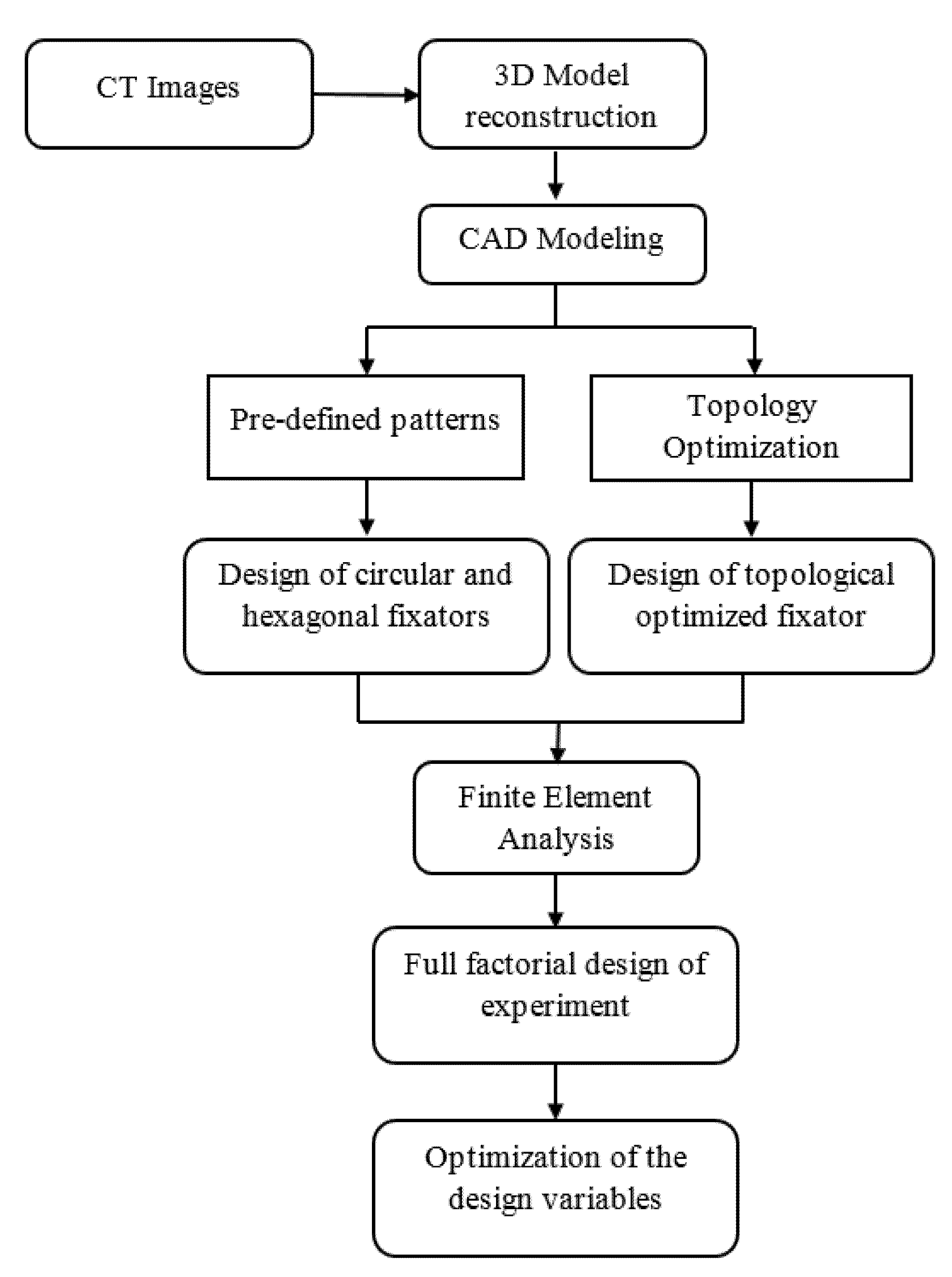
2. Modeling and Simulation
2.1. Design Techniques
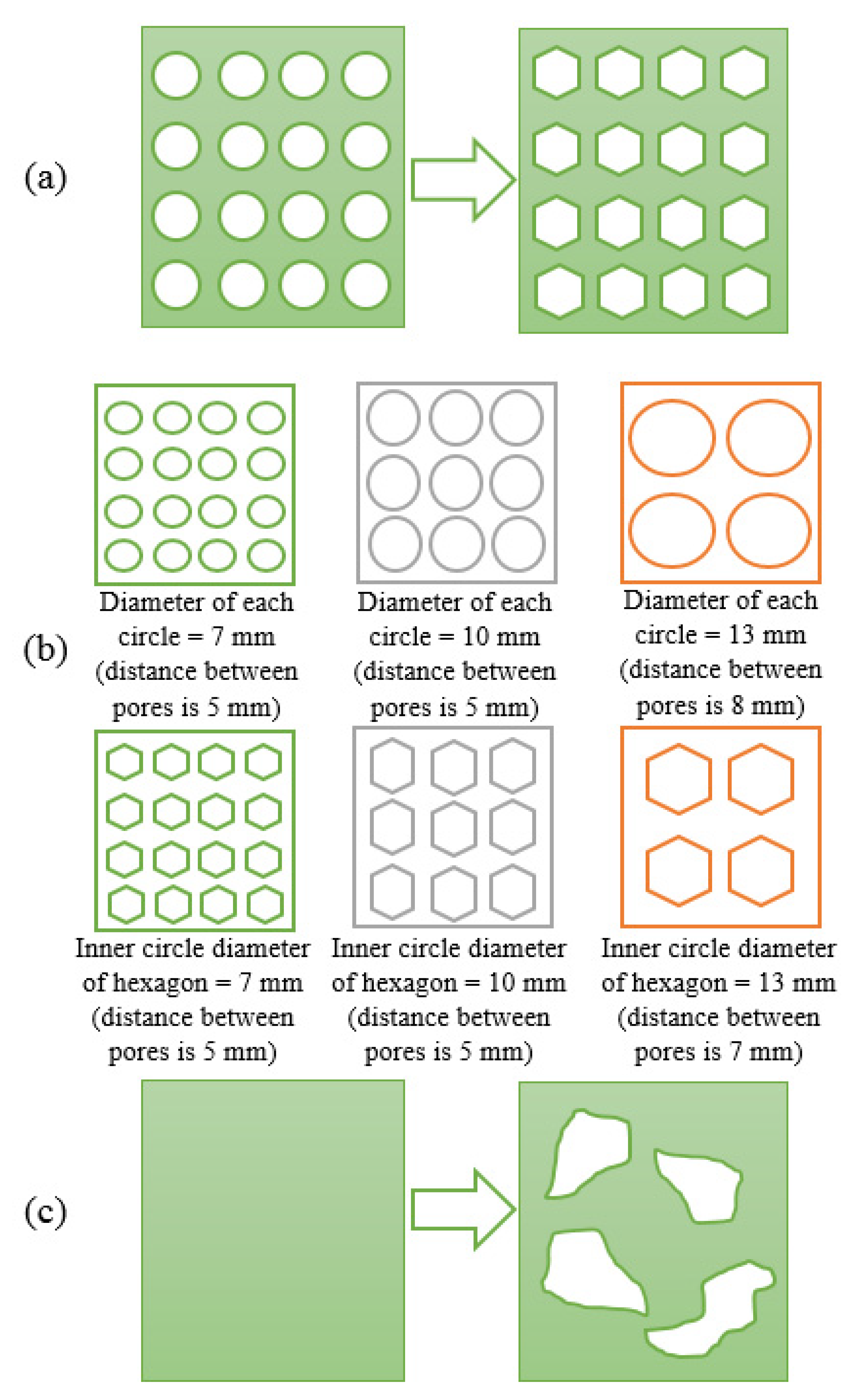
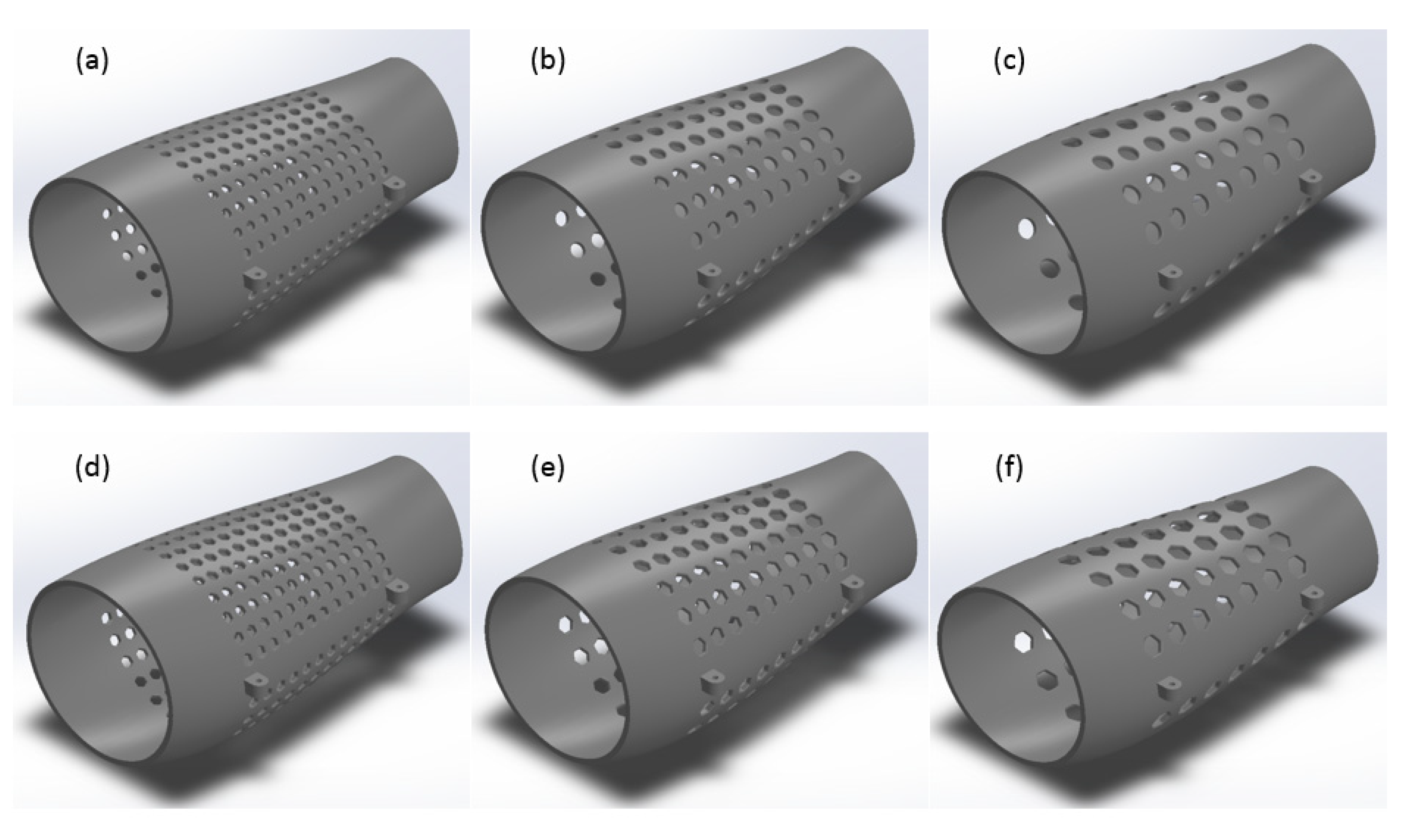
- Case 1: the first method was used to investigate the geometric effect of two imposed patterns (circle and hexagon) on the performance of the fixator (Figure 3a);
- Case 2: investigates the effect of changing both the number and the geometric dimensions of the patterns considered in Case 1 for a fixed porosity value (Figure 3b). In this case, three different scenarios were also considered:
- ◦
- Case 2a—high number of patterned elements: elements with 7 mm diameter.
- ◦
- Case 2b—middle number of patterned elements: elements with 10 mm diameter.
- ◦
- Case 2c—low number of patterned elements: elements with 13 mm diameter.
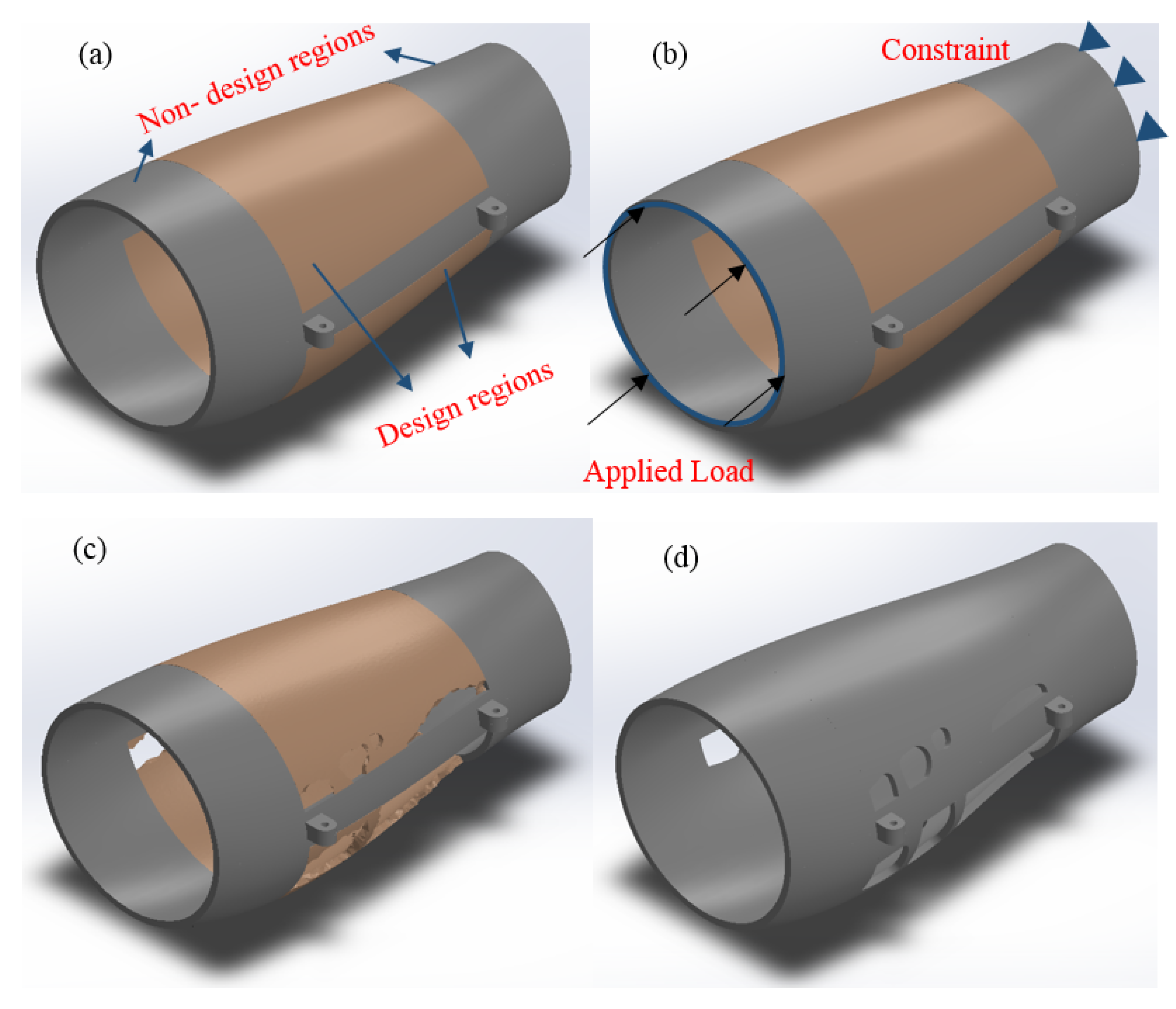
- Case 3: the middle section of the external fixator was modified using topology optimization (Figure 3c).
2.1.1. Design with Pre-Defined Patterns
2.1.2. Topology Optimization
2.2. Structural Analysis of the External Fixator
2.3. Convergence Analysis
2.4. Full Factorial Design
2.5. Statistical Analysis—Analysis of Variance (ANOVA)
2.6. Performance Measures
3. Results and Discussion
3.1. ANOVA
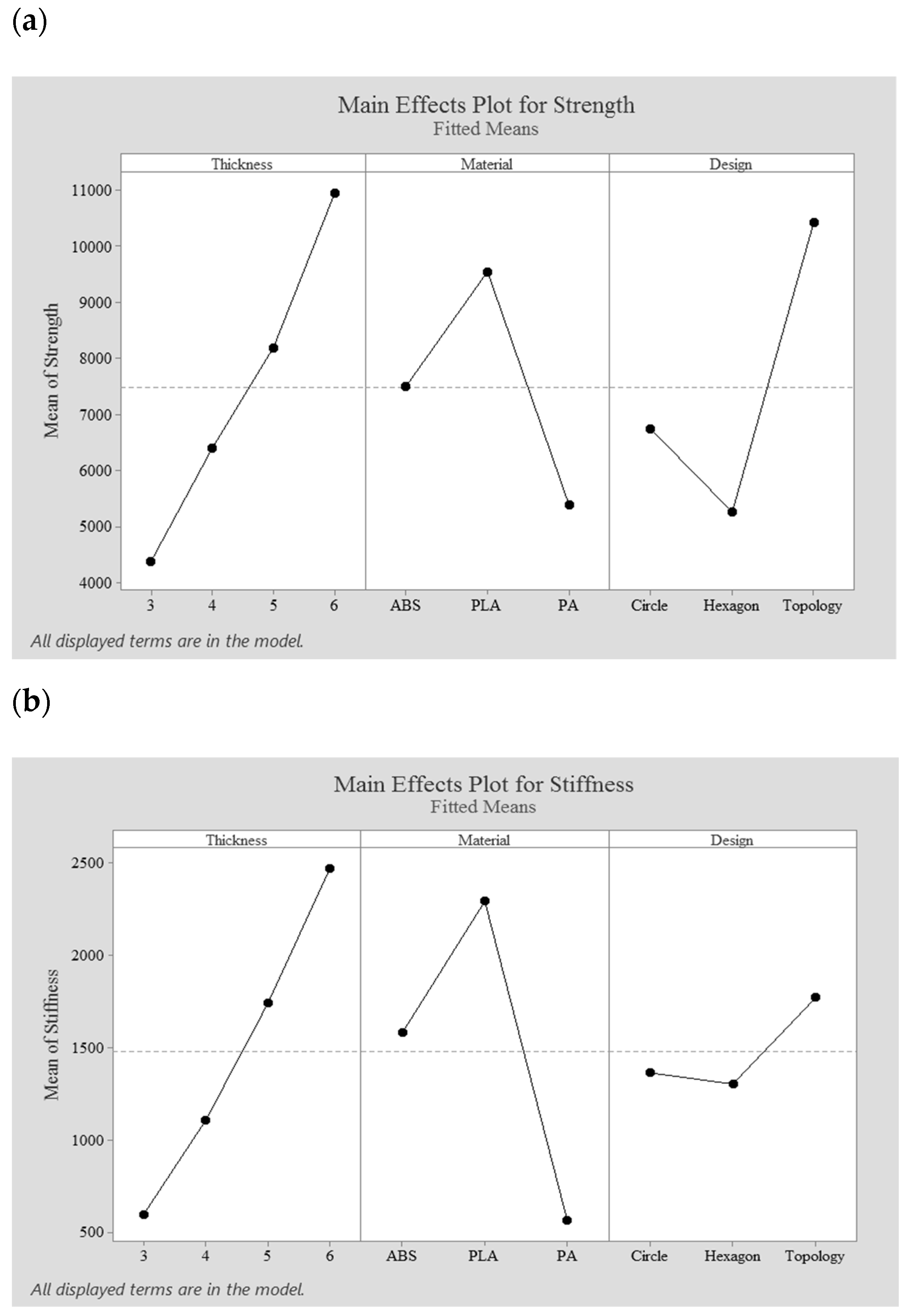
3.2. Main Effects
3.3. Pareto Chart
3.4. Optimized Performance Measures
- Fixator’s thickness: 4 mm
- Material: PLA
- Design: topology optimized fixator.
4. Conclusions
Author Contributions
Funding
Institutional Review Board Statement
Informed Consent Statement
Data Availability Statement
Acknowledgments
Conflicts of Interest
References
- Dichio, G.; Calì, M.; Terzini, M.; Putame, G.; Zanetti, E.M.; Costa, P.; Audenino, A.L. Engineering and manufacturing of a dynamizable fracture fixation device system. Appl. Sci. 2020, 10, 6844. [Google Scholar] [CrossRef]
- Maia, F.R.; Correlo, V.M.; Oliveira, J.M.; Reis, R.L. Natural origin materials for bone tissue engineering: Properties, processing, and performance. In Principles of Regenerative Medicine, 3rd ed.; Atala, A., Lanza, R., Mikos, A., Nerem, R., Eds.; Academic Press: Cambridge, MA, USA, 2019; pp. 535–558. [Google Scholar]
- Al-Tamimi, A.A.; Fernandes, P.R.A.; Peach, C.; Cooper, G.; Diver, C.; Bartolo, P.J. Metallic bone fixation implants: Novel design approach for reducing the stress shielding phenomenon. Virtual Phys. Prototyp. 2017, 12, 141–151. [Google Scholar] [CrossRef]
- Ho-Shui-Ling, A.; Bolander, J.; Rustom, L.E.; Johnson, A.W.; Luyten, F.P.; Picart, C. Bone regeneration strategies: Engineered scaffolds, bioactive molecules and stem cells current stage and future perspectives. Biomaterials 2018, 180, 143–162. [Google Scholar] [CrossRef] [PubMed]
- Wahab, A.H.A.; Wui, N.B.; Kadir, M.R.A.; Ramlee, M.H. Biomechanical evaluation of three different configurations of external fixators for treating distal third tibia fracture: Finite element analysis in axial, bending and torsion load. Comput. Biol. Med. 2020, 127, 104062. [Google Scholar] [CrossRef]
- Murphy, D.P.; Webster, J.B.; Lovergreen, W.; Simoncini, A. Lower limb orthoses. In Braddom’s Physical Medicine and Rehabilitation, 6th ed.; Cifu, D.X., Ed.; Elsevier: Amsterdam, The Netherlands, 2021; pp. 229–247. [Google Scholar]
- Alqahtani, M.S.; Cooper, G.; Al-Tamimi, A.A.; Almeida, H.A.; Bartolo, P.J. A review on the use of additive manufacturing to produce lower limb orthoses. Prog. Addit. Manuf. 2019, 5, 1–10. [Google Scholar] [CrossRef] [Green Version]
- Encinas-Ullán, C.A.; Martínez-Diez, J.M.; Rodríguez-Merchán, E.C. The use of external fixation in the emergency department: Applications, common errors, complications and their treatment. EFORT Open Rev. 2020, 5, 204–214. [Google Scholar] [CrossRef] [PubMed]
- Sellei, R.M.; Kobbe, P.; Dadgar, A.; Pfeifer, R.; Behrens, M.; von Oldenburg, G.; Pape, H.C. External fixation design evolution enhances biomechanical frame performance. Injury 2015, 46, S23–S26. [Google Scholar] [CrossRef]
- Parvizi, J.; Kim, G.K. External fxation. In High Yield Orthopaedics, 1st ed.; Parvizi, J., Kim, G.K., Eds.; Elsevier: Amsterdam, The Netherlands, 2010; pp. 171–172. [Google Scholar]
- Bliven, E.K.; Greinwald, M.; Hackl, S.; Augat, P. External fixation of the lower extremities: Biomechanical perspective and recent innovations. Injury 2019, 50, S10–S17. [Google Scholar] [CrossRef] [PubMed]
- Kani, K.K.; Porrino, J.A.; Chew, F.S. External fixators: Looking beyond the hardware maze. Skelet. Radiol. 2020, 49, 359–374. [Google Scholar] [CrossRef] [PubMed]
- Friis, E.A.; DeCoster, T.A.; Thomas, J.C. Mechanical testing of fracture fixation devices. In Mechanical Testing of Orthopaedic Implants, 1st ed.; Friis, E.A., Ed.; Woodhead Publishing: Cambridge, UK, 2017; pp. 131–141. [Google Scholar]
- Moss, D.P.; Tejwani, N.C. Biomechanics of external fixation: A review of the literature. Bull. NYU Hosp. Jt. Dis. 2007, 65, 294–299. [Google Scholar]
- Sun, J.; Li, Q.; Gao, F.; Xiang, Z.; Huang, Q.; Li, L. Application of the Ilizarov technique for knee joint arthrodesis as a treatment for end-stage tuberculosis of the knee. BMC Musculoskelet. Disord. 2020, 21, 579. [Google Scholar] [CrossRef] [PubMed]
- Li, J.; Zhao, X.; Hu, X.; Tao, C.; Ji, R. A theoretical analysis and finite element simulation of fixator–bone system stiffness on healing progression. J. Appl. Biomater. Funct. Mater. 2018, 16, 115–125. [Google Scholar] [CrossRef] [Green Version]
- Watson, M.A.; Mathias, K.J.; Maffulli, N. External ring fixators: An overview. Proc. Inst. Mech. Eng. Part H J. Eng. Med. 2000, 214, 459–470. [Google Scholar] [CrossRef]
- Zhang, G. Geometric and material nonlinearity in tensioned wires of an external fixator. Clin. Biomech. 2004, 19, 513–518. [Google Scholar] [CrossRef] [PubMed]
- Watson, M.A.; Maffulli, N.; Hukins, D.W.L.; Matthias, K.J. Yielding of the clamped-wire system in the Ilizarov external fixator. Proc. Inst. Mech. Eng. Part H J. Eng. Med. 2003, 217, 367–374. [Google Scholar] [CrossRef] [PubMed]
- Baidya, P.R.; Ramakrishna, S.; Rahman, M.; Ritchie, A. Advanced textile composite ring for Ilizarov external fixator system. Proc. Inst. Mech. Eng. Part H J. Eng. Med. 2001, 215, 11–23. [Google Scholar] [CrossRef] [PubMed]
- Sternick, M.B.; Dallacosta, D.; Bento, D.A.; Reis, M.L. Relationship between rigidity of external fixator and number of pins: Computer analysis using finite elements. Rev. Bras. Ortop. 2012, 47, 646–650. [Google Scholar] [CrossRef] [PubMed] [Green Version]
- Elmedin, M.; Vahid, A.; Nedim, P.; Nedžad, R. Finite element analysis and experimental testing of stiffness of the Sarafix external fixator. Procedia Eng. 2015, 100, 1598–1607. [Google Scholar] [CrossRef] [Green Version]
- Kania, D.; Yunus, R.; Omar, R.; Rashid, S.A.; Jan, B.M. Rheological investigation of synthetic-based drilling fluid containing non-ionic surfactant pentaerythritol ester using full factorial design. Colloids Surf. A Physicochem. Eng. Asp. 2021, 625, 126700. [Google Scholar] [CrossRef]
- Chen, R.; Rao, P.; Lu, Y.; Reutzel, E.W.; Yang, H. Recurrence network analysis of design-quality interactions in additive manufacturing. Addit. Manuf. 2021, 39, 101861. [Google Scholar]
- Baraheni, M.; Alaei, A.; Amini, S. Ultrasonic-assisted friction drilling process of aerospace aluminum alloy (AA7075): FEA and experimental study. Int. J. Lightweight Mater. Manuf. 2021, 4, 315–322. [Google Scholar]
- Țîțu, A.M.; Sandu, A.V.; Pop, A.B.; Țîțu, Ș.; Frățilă, D.N.; Ceocea, C.; Boroiu, A. Design of experiment in the milling process of aluminum alloys in the aerospace industry. Appl. Sci. 2020, 10, 6951. [Google Scholar] [CrossRef]
- Ahmed, Y.; Yasir, M.; Ur Rehman, M.A. Fabrication and characterization of zein/hydroxyapatite composite coatings for biomedical applications. Surfaces 2020, 3, 237–250. [Google Scholar] [CrossRef]
- Sellei, R.M.; Kobbe, P.; Dienstknecht, T.; Lichte, P.; Pfeifer, R.; Behrens, M.; Brianza, S.; Pape, H.C. Biomechanical properties of different external fixator frame configurations. Eur. J. Trauma Emerg. Surg. 2015, 41, 313–318. [Google Scholar] [CrossRef] [PubMed]
- Wu, C.; Zheng, K.; Fang, J.; Steven, G.P.; Li, Q. Time-dependent topology optimization of bone plates considering bone remodeling. Comput. Methods Appl. Mech. Eng. 2020, 359, 1–18. [Google Scholar] [CrossRef]
- Murr, L.E. Metallurgy principles applied to powder bed fusion 3D printing/additive manufacturing of personalized and optimized metal and alloy biomedical implants: An overview. J. Mater. Res. Technol. 2020, 9, 1087–1103. [Google Scholar] [CrossRef]
- Salmi, M. Additive manufacturing processes in medical applications. Materials 2021, 14, 191. [Google Scholar] [CrossRef] [PubMed]
- Bikas, H.; Stavropoulos, P.; Chryssolouris, G. Additive manufacturing methods and modeling approaches: A critical review. Int. J. Adv. Manuf. Technol. 2016, 83, 389–405. [Google Scholar] [CrossRef] [Green Version]
- Zhu, B.; Zhang, X.; Zhang, H.; Liang, J.; Zang, H.; Li, H.; Wang, R. Design of compliant mechanisms using continuum topology optimization: A review. Mech. Mach. Theory 2020, 143, 103622. [Google Scholar] [CrossRef]
- Al-Tamimi, A.A.; Hernandez, M.A.; Omar, A.; Morales-Aldana, D.F.; Peach, C.; Bartolo, P. Mechanical, biological and tribological behaviour of fixation plates 3D printed by electron beam and selective laser melting. Int. J. Adv. Manuf. Technol. 2020, 109, 673–688. [Google Scholar] [CrossRef]
- Brackett, D.; Ashcroft, I.; Hague, R. Topology Optimization for Additive Manufacturing. In Proceedings of the 22nd Annual International Solid Freeform Fabrication (SFF) Symposium, Austin, TX, USA, 10–13 August 2011. [Google Scholar]
- Long, H.; Hu, Y.; Jin, X.; Yu, H.; Zhu, H. An optimization procedure for spot-welded structures based on SIMP method. Comput. Mater. Sci. 2016, 117, 602–607. [Google Scholar] [CrossRef]
- Berrocal, L.; Fernández, R.; González, S.; Periñán, A.; Tudela, S.; Vilanova, J.; Rubio, L.; Márquez, J.M.M.; Guerrero, J.; Lasagni, F. Topology optimization and additive manufacturing for aerospace components. Prog. Addit. Manuf. 2019, 4, 83–95. [Google Scholar] [CrossRef]
- Białkowski, S. Structural optimization methods as a new toolset for architects. In Proceedings of the 34th eCAADe Conference—Complexity & Simplicity, Oulu, Finland, 22–26 August 2016. [Google Scholar]
- Al-Tamimi, A.A.; Quental, C.; Folgado, J.; Peach, C.; Bartolo, P. Stress analysis in a bone fracture fixed with topology-optimized plates. Biomech. Model. Mechanobiol. 2020, 19, 693–699. [Google Scholar] [CrossRef] [PubMed] [Green Version]
- Jansari, T.; Deiab, I. Comparative study of a topologically optimized lower limb prosthesis. Int. J. Interact. Des. Manuf. 2019, 13, 645–657. [Google Scholar] [CrossRef]
- Al-Tamimi, A.A.; Peach, C.; Fernandes, P.R.; Cseke, A.; Bartolo, P.J. Topology optimization to reduce the stress shielding effect for orthopedic applications. Procedia CIRP 2017, 65, 202–206. [Google Scholar] [CrossRef]
- Shi, D.; Liu, K.; Zhang, H.; Wang, X.; Li, G.; Zheng, L. Investigating the biomechanical function of the plate-type external fixator in the treatment of tibial fractures: A biomechanical study. BMC Musculoskelet. Disord. 2020, 21, 1–9. [Google Scholar] [CrossRef] [PubMed] [Green Version]
- Ghimire, S.; Miramini, S.; Richardson, M.; Mendis, P.; Zhang, L. Effects of dynamic loading on fracture healing under different locking compression plate configurations: A finite element study. J. Mech. Behav. Biomed. Mater. 2019, 94, 74–85. [Google Scholar] [CrossRef] [PubMed]
- Kim, S.-H.; Chang, S.-H.; Son, D.-S. Finite element analysis of the effect of bending stiffness and contact condition of composite bone plates with simple rectangular cross-section on the bio-mechanical behaviour of fractured long bones. Compos. Part B Eng. 2011, 42, 1731–1738. [Google Scholar] [CrossRef]
- Ultimaker. Available online: https://ultimaker.com/materials (accessed on 24 October 2020).
- Blaya, F.; Pedro, P.S.; Pedro, A.B.S.; Lopez-Silva, J.; Juanes, J.A.; D’Amato, R. Design of a functional splint for rehabilitation of achilles tendon injury using advanced manufacturing (AM) techniques. Implementation study. J. Med Syst. 2019, 43, 122–136. [Google Scholar] [CrossRef] [PubMed]
- Kelly, S.; Paterson, A.; Bibb, R. Design rules for additively manufactured wrist splints created using design of experiment methods. In Proceedings of the 29th Annual International Solid Freeform Fabrication (SFF) Symposium, Austin, TX, USA, 13–15 August 2018. [Google Scholar]
- Mohammed, M.I.; Fay, P. Design and additive manufacturing of a patient specific polymer thumb splint concept. In Proceedings of the 29th Annual International Solid Freeform Fabrication (SFF) Symposium, Austin, TX, USA, 13–15 August 2018. [Google Scholar]


| PLA | ABS | PA | |
|---|---|---|---|
| Young’s Modulus (GPa) | 2.35 | 1.62 | 0.58 |
| Poisson Ratio | 0.39 | 0.39 | 0.35 |
| Yield Strength (MPa) | 49.5 | 39 | 27.8 |
| Density at 20 °C (gcm−3) | 1.24 | 1.10 | 1.14 |
| Design | Diameter (mm) | Von Mises Stresses (MPa) | Maximum Displacement (mm) | Strength (KN) | Stiffness (KN/mm) |
|---|---|---|---|---|---|
| Circle | 7 | 4.75 | 0.438 | 7.28 | 1.59 |
| 10 | 4.79 | 0.450 | 7.23 | 1.55 | |
| 13 | 4.84 | 0.452 | 7.15 | 1.54 | |
| Hexagon | 7 | 6.34 | 0.458 | 5.46 | 1.52 |
| 10 | 7.12 | 0.467 | 4.86 | 1.50 | |
| 13 | 7.79 | 0.474 | 4.44 | 1.47 |
| Factor | Number of Levels | Level Values | |||
|---|---|---|---|---|---|
| Level 1 | Level 2 | Level 3 | Level 4 | ||
| Thickness (mm) | 4 | 3 | 4 | 5 | 6 |
| Material | 3 | ABS | PLA | PA | - |
| Design | 3 | Circle | Hexagon | Topology | - |
| Std Order | Thickness (mm) | Material | Design | Strength (KN) | Stiffness (KN/mm) |
|---|---|---|---|---|---|
| 1 | 3 | ABS | Circles | 3.96 | 0.60 |
| 2 | 3 | ABS | Hexagon | 3.26 | 0.58 |
| 3 | 3 | ABS | Topology | 6.02 | 0.73 |
| 4 | 3 | PLA | Circles | 5.03 | 0.88 |
| 5 | 3 | PLA | Hexagon | 4.14 | 0.84 |
| 6 | 3 | PLA | Topology | 7.62 | 1.06 |
| 7 | 3 | PA | Circles | 2.84 | 0.22 |
| 8 | 3 | PA | Hexagon | 2.33 | 0.21 |
| 9 | 3 | PA | Topology | 4.25 | 0.26 |
| 10 | 4 | ABS | Circles | 5.73 | 1.10 |
| 11 | 4 | ABS | Hexagon | 4.31 | 1.05 |
| 12 | 4 | ABS | Topology | 9.36 | 1.40 |
| 13 | 4 | PLA | Circles | 7.29 | 1.60 |
| 14 | 4 | PLA | Hexagon | 5.46 | 1.53 |
| 15 | 4 | PLA | Topology | 11.81 | 2.02 |
| 16 | 4 | PA | Circles | 4.11 | 0.39 |
| 17 | 4 | PA | Hexagon | 3.06 | 0.38 |
| 18 | 4 | PA | Topology | 6.48 | 0.50 |
| 19 | 5 | ABS | Circles | 7.70 | 1.71 |
| 20 | 5 | ABS | Hexagon | 6.10 | 1.64 |
| 21 | 5 | ABS | Topology | 10.73 | 2.23 |
| 22 | 5 | PLA | Circles | 9.77 | 2.48 |
| 23 | 5 | PLA | Hexagon | 7.74 | 2.37 |
| 24 | 5 | PLA | Topology | 13.85 | 3.24 |
| 25 | 5 | PA | Circles | 5.49 | 0.61 |
| 26 | 5 | PA | Hexagon | 4.34 | 0.58 |
| 27 | 5 | PA | Topology | 7.98 | 0.80 |
| 28 | 6 | ABS | Circles | 9.73 | 2.41 |
| 29 | 6 | ABS | Hexagon | 7.54 | 2.30 |
| 30 | 6 | ABS | Topology | 15.56 | 3.21 |
| 31 | 6 | PLA | Circles | 12.35 | 3.50 |
| 32 | 6 | PLA | Hexagon | 9.55 | 3.34 |
| 33 | 6 | PLA | Topology | 19.93 | 4.65 |
| 34 | 6 | PA | Circles | 6.93 | 0.86 |
| 34 | 6 | PA | Hexagon | 5.31 | 0.82 |
| 36 | 6 | PA | Topology | 11.53 | 1.15 |
| Source | Degree of Freedom | Sum of Square | Mean Square | F-Value | p-Value |
|---|---|---|---|---|---|
| Model | 23 | 525,641,896 | 22,853,995 | 273.54 | 0.000 |
| Linear | 7 | 482,345,330 | 68,906,476 | 824.75 | 0.000 |
| Thickness | 3 | 208,921,198 | 69,640,399 | 833.53 | 0.000 |
| Material | 2 | 103,717,907 | 51,858,954 | 620.71 | 0.000 |
| Design | 2 | 169,706,225 | 84,853,113 | 1015.62 | 0.000 |
| 2-Way Interactions | 16 | 43,296,566 | 2,706,035 | 32.39 | 0.000 |
| Thickness*Material | 6 | 10,120,405 | 1,686,734 | 20.19 | 0.000 |
| Thickness*Design | 6 | 24,983,889 | 4,163,982 | 49.84 | 0.000 |
| Material*Design | 4 | 8,192,272 | 2,048,068 | 24.51 | 0.000 |
| Error | 12 | 1,002,579 | 83,548 | - | - |
| Total | 35 | 526,644,475 | - | - | - |
| Source | Degree of Freedom | Sum of Square | Mean Square | F-Value | p-Value |
|---|---|---|---|---|---|
| Model | 23 | 42,226,405 | 1,835,931 | 191.79 | 0.000 |
| Linear | 7 | 37,313,541 | 5,330,506 | 556.86 | 0.000 |
| Thickness | 3 | 17,684,260 | 5,894,753 | 615.81 | 0.000 |
| Material | 2 | 18,079,921 | 9,039,961 | 944.38 | 0.000 |
| Design | 2 | 1,549,359 | 774,680 | 80.93 | 0.000 |
| 2-Way Interactions | 16 | 4,912,865 | 307,054 | 32.08 | 0.000 |
| Thickness*Material | 6 | 4,055,959 | 675,993 | 70.62 | 0.000 |
| Thickness*Design | 6 | 5,00,306 | 83,384 | 8.71 | 0.001 |
| Material*Design | 4 | 356,600 | 89,150 | 9.31 | 0.001 |
| Error | 12 | 114,869 | 9572 | - | - |
| Total | 35 | 42,341,274 | - | - | - |
Publisher’s Note: MDPI stays neutral with regard to jurisdictional claims in published maps and institutional affiliations. |
© 2021 by the authors. Licensee MDPI, Basel, Switzerland. This article is an open access article distributed under the terms and conditions of the Creative Commons Attribution (CC BY) license (https://creativecommons.org/licenses/by/4.0/).
Share and Cite
Alqahtani, M.S.; Al-Tamimi, A.A.; Hassan, M.H.; Liu, F.; Bartolo, P. Optimization of a Patient-Specific External Fixation Device for Lower Limb Injuries. Polymers 2021, 13, 2661. https://doi.org/10.3390/polym13162661
Alqahtani MS, Al-Tamimi AA, Hassan MH, Liu F, Bartolo P. Optimization of a Patient-Specific External Fixation Device for Lower Limb Injuries. Polymers. 2021; 13(16):2661. https://doi.org/10.3390/polym13162661
Chicago/Turabian StyleAlqahtani, Mohammed S., Abdulsalam Abdulaziz Al-Tamimi, Mohamed H. Hassan, Fengyuan Liu, and Paulo Bartolo. 2021. "Optimization of a Patient-Specific External Fixation Device for Lower Limb Injuries" Polymers 13, no. 16: 2661. https://doi.org/10.3390/polym13162661
APA StyleAlqahtani, M. S., Al-Tamimi, A. A., Hassan, M. H., Liu, F., & Bartolo, P. (2021). Optimization of a Patient-Specific External Fixation Device for Lower Limb Injuries. Polymers, 13(16), 2661. https://doi.org/10.3390/polym13162661