
In Vivo Imaging of Biodegradable Implants and Related Tissue Biomarkers

 ,
,  , , ,
, , , 

Abstract
1. Introduction
1.1. Background
1.2. Tissue Response
1.3. Effects of Implant Structure
2. Features of the Imaging Techniques
2.1. Computed Tomography
2.2. Positron Emission Tomography
2.3. Ultrasound Imaging
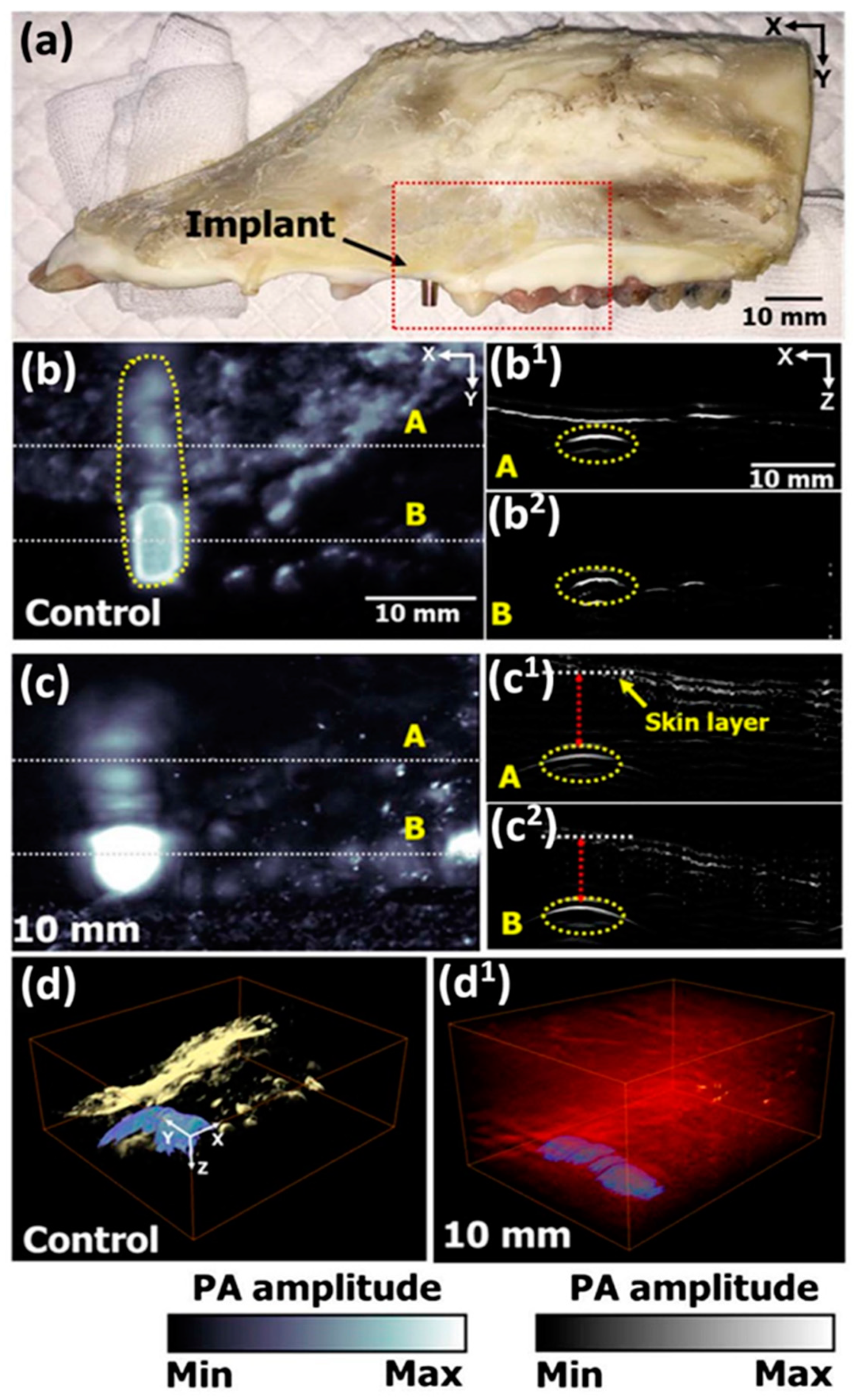
2.4. Photoacoustic Imaging
2.5. Magnetic Resonance Imaging
3. Discussion and Conclusions
Author Contributions
Funding
Institutional Review Board Statement
Informed Consent Statement
Data Availability Statement
Conflicts of Interest
Appendix A

| Total Attenuation without Coherent Scattering cm2/g | ||||||||||||||||||||
|---|---|---|---|---|---|---|---|---|---|---|---|---|---|---|---|---|---|---|---|---|
| Metals | Ceramics | Polymers | Tissues | |||||||||||||||||
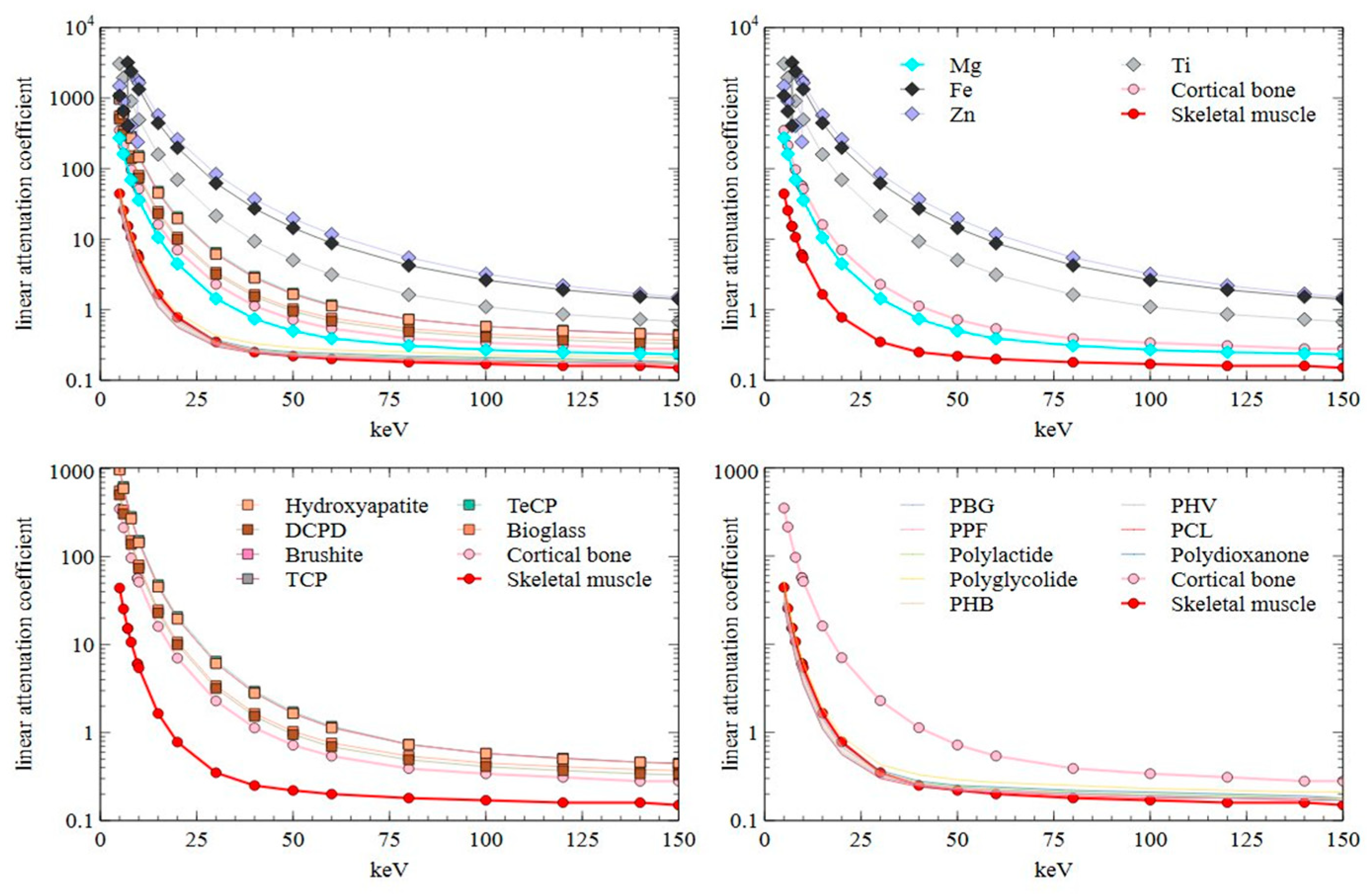
| keV | Mg | Fe | Zn | Ti | Hydroxy-Apatite | DCD | Brushite | TCP | TeCP | Bioglass | Poly (γ-Benzyl-l-Glutamate) | Poly-Propylene Fumarate | Poly- Lactide | Poly-Glycolide | Poly- Hydroxy-Butyrate | Poly- Hydroxy-Valerate | Poly-Capro-Lactone | Poly-Dioxanone | Cortical Bone | Skeletal Muscle |
| 5 | 157.20 | 137.40 | 208.70 | 682.00 | 312.00 | 217.60 | 217.60 | 309.30 | 329.80 | 207.80 | 24.68 | 30.31 | 30.39 | 33.85 | 28.07 | 26.39 | 25.13 | 31.08 | 182.60 | 41.98 |
| 6 | 92.87 | 82.78 | 126.40 | 430.80 | 191.30 | 132.60 | 132.60 | 189.60 | 202.40 | 125.90 | 14.11 | 17.37 | 17.42 | 19.42 | 16.08 | 15.11 | 14.38 | 17.82 | 111.30 | 24.26 |
| 7.112 | 51.45 | 14.50 | ||||||||||||||||||
| 7.112 | 406.00 | 14.52 | ||||||||||||||||||
| 8 | 39.91 | 304.10 | 56.75 | 201.20 | 87.12 | 59.89 | 59.89 | 86.28 | 92.34 | 56.34 | 5.83 | 7.18 | 7.21 | 8.04 | 6.66 | 6.26 | 5.96 | 7.38 | 50.34 | 10.16 |
| 9.659 | 33.45 | 29.61 | 5.74 | |||||||||||||||||
| 9.659 | 252.00 | 29.63 | 5.75 | |||||||||||||||||
| 10 | 20.54 | 169.50 | 231.50 | 109.80 | 46.61 | 31.88 | 31.88 | 46.14 | 49.45 | 29.80 | 2.96 | 3.64 | 3.66 | 4.07 | 3.37 | 3.18 | 3.02 | 3.74 | 26.84 | 5.18 |
| 15 | 6.07 | 56.34 | 80.24 | 35.29 | 14.58 | 9.92 | 9.92 | 14.42 | 15.49 | 9.19 | 0.93 | 1.12 | 1.13 | 1.24 | 1.05 | 0.99 | 0.95 | 1.15 | 8.39 | 1.57 |
| 20 | 2.58 | 25.17 | 36.55 | 15.45 | 6.32 | 4.31 | 4.31 | 6.25 | 6.71 | 3.97 | 0.48 | 0.54 | 0.55 | 0.59 | 0.52 | 0.50 | 0.49 | 0.56 | 3.66 | 0.74 |
| 30 | 0.83 | 7.89 | 11.71 | 4.75 | 1.97 | 1.38 | 1.37 | 1.95 | 2.09 | 1.26 | 0.26 | 0.27 | 0.28 | 0.28 | 0.27 | 0.27 | 0.26 | 0.28 | 1.19 | 0.33 |
| 40 | 0.43 | 3.45 | 5.16 | 2.08 | 0.91 | 0.66 | 0.66 | 0.90 | 0.95 | 0.61 | 0.21 | 0.21 | 0.21 | 0.22 | 0.21 | 0.21 | 0.21 | 0.21 | 0.59 | 0.24 |
| 50 | 0.29 | 1.83 | 2.74 | 1.12 | 0.53 | 0.41 | 0.41 | 0.53 | 0.55 | 0.38 | 0.18 | 0.18 | 0.19 | 0.19 | 0.20 | 0.19 | 0.19 | 0.19 | 0.38 | 0.21 |
| 60 | 0.22 | 1.11 | 1.65 | 0.70 | 0.36 | 0.30 | 0.30 | 0.36 | 0.38 | 0.28 | 0.18 | 0.18 | 0.18 | 0.18 | 0.18 | 0.18 | 0.18 | 0.18 | 0.28 | 0.19 |
| 80 | 0.18 | 0.54 | 0.77 | 0.36 | 0.24 | 0.21 | 0.21 | 0.23 | 0.24 | 0.20 | 0.17 | 0.16 | 0.17 | 0.16 | 0.17 | 0.17 | 0.17 | 0.17 | 0.20 | 0.17 |
| 100 | 0.16 | 0.33 | 0.45 | 0.24 | 0.19 | 0.18 | 0.18 | 0.18 | 0.19 | 0.17 | 0.16 | 0.15 | 0.16 | 0.15 | 0.15 | 0.16 | 0.16 | 0.16 | 0.18 | 0.16 |
| 120 | 0.14 | 0.24 | 0.31 | 0.19 | 0.16 | 0.16 | 0.16 | 0.16 | 0.16 | 0.15 | 0.15 | 0.14 | 0.15 | 0.14 | 0.15 | 0.15 | 0.16 | 0.15 | 0.16 | 0.15 |
| 140 | 0.14 | 0.19 | 0.24 | 0.16 | 0.15 | 0.15 | 0.15 | 0.15 | 0.15 | 0.14 | 0.14 | 0.14 | 0.14 | 0.14 | 0.15 | 0.15 | 0.15 | 0.15 | 0.15 | 0.15 |
| 150 | 0.13 | 0.18 | 0.21 | 0.15 | 0.14 | 0.14 | 0.14 | 0.14 | 0.14 | 0.14 | 0.14 | 0.14 | 0.14 | 0.14 | 0.15 | 0.14 | 0.15 | 0.14 | 0.15 | 0.14 |
References
- Teo, A.J.T.; Mishra, A.; Park, I.; Kim, Y.J.; Park, W.T.; Yoon, Y.J. Polymeric Biomaterials for Medical Implants and Devices. ACS Biomater. Sci. Eng. 2016, 2, 454–472. [Google Scholar] [CrossRef]
- Saini, M. Implant Biomaterials: A Comprehensive Review. World J. Clin. Cases 2015, 3, 52. [Google Scholar] [CrossRef]
- Rahim, M.I.; Ullah, S.; Mueller, P.P. Advances and Challenges of Biodegradable Implant Materials with a Focus on Magnesium-Alloys and Bacterial Infections. Metals 2018, 8, 532. [Google Scholar] [CrossRef]
- Jaiswal, S.; Dubey, A.; Lahiri, D. In Vitro Biodegradation and Biocompatibility of Mg–HA-Based Composites for Orthopaedic Applications: A Review. J. Indian Inst. Sci. 2019, 99, 303–327. [Google Scholar] [CrossRef]
- Zafar, M.S.; Ullah, R.; Qamar, Z.; Fareed, M.A.; Amin, F.; Khurshid, Z.; Sefat, F. Properties of dental biomaterials. In Avanced Dental Biomaterials; Woodhead Publishing: Duxford, UK, 2019. [Google Scholar]
- FDA-NIH Biomarker Working Group. BEST (Biomarkers, EndpointS, and Other Tools) Resource; Food and Drug Administration (US): Silver Spring, MD, USA, 2016.
- Chen, L.; Deng, H.; Cui, H.; Fang, J.; Zuo, Z.; Deng, J.; Li, Y.; Wang, X.; Zhao, L. Inflammatory Responses and Inflammation-Associated Diseases in Organs. Oncotarget 2018, 9, 7204–7218. [Google Scholar] [CrossRef] [PubMed]
- Shrivastava, S. ASM International. In Medical Device Materials, Proceedings of the Materials & Processes for Medical Devices Conference 2003, 8–10 September 2003, Anaheim, CA, USA; ASM International: Geauga, OH, USA, 2004. [Google Scholar]
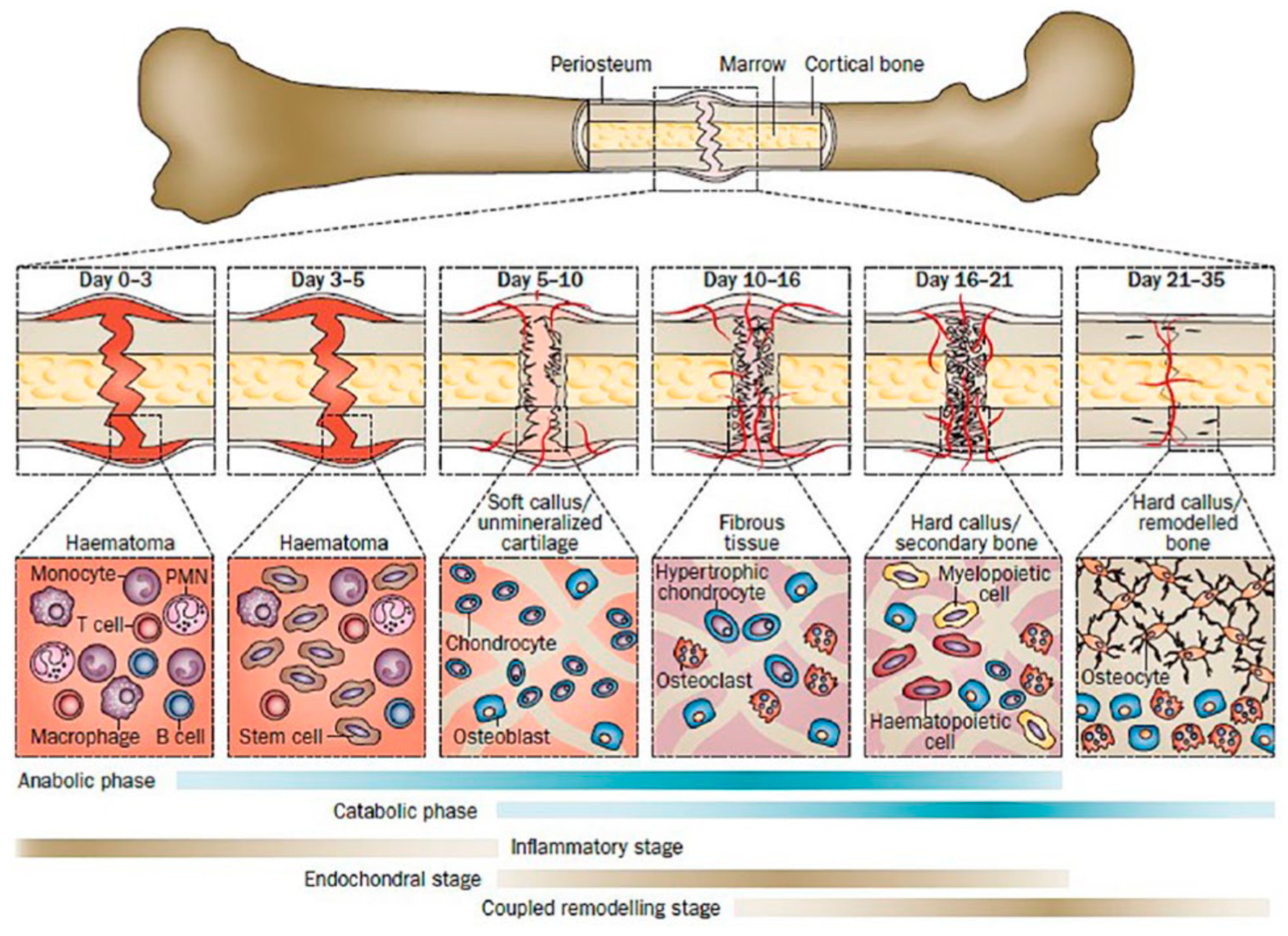
- Loi, F.; Córdova, L.A.; Pajarinen, J.; Lin, T.H.; Yao, Z.; Goodman, S.B. Inflammation, Fracture and Bone Repair. Bone 2016, 86, 119–130. [Google Scholar] [CrossRef]
- Einhorn, T.A.; Gerstenfeld, L.C. Fracture Healing: Mechanisms and Interventions. Nat. Rev. Rheumatol. 2015, 11, 45–54. [Google Scholar] [CrossRef] [PubMed]
- Radha, R.; Sreekanth, D. Insight of Magnesium Alloys and Composites for Orthopedic Implant Applications—A Review. J. Magnes. Alloys 2017, 5, 286–312. [Google Scholar] [CrossRef]
- Wahl, D.A.; Czernuszka, J.T. Collagen-Hydroxyapatite Composites for Hard Tissue Repair. Eur. Cells Mater. 2006, 11, 43–56. [Google Scholar] [CrossRef]
- Sun, D.; Chen, Y.; Tran, R.T.; Xu, S.; Xie, D.; Jia, C.; Wang, Y.; Guo, Y.; Zhang, Z.; Guo, J.; et al. Citric Acid-Based Hydroxyapatite Composite Scaffolds Enhance Calvarial Regeneration. Sci. Rep. 2014, 4, 1–9. [Google Scholar] [CrossRef] [PubMed]
- Karthik, V.; Pabi, S.K.; Chowdhury, S.K.R. Development of Hydroxyapatite/Polyvinyl Alcohol Bionanocomposite for Prosthesis Implants. IOP Conf. Ser. Mater. Sci. Eng. 2018, 314, 12031. [Google Scholar] [CrossRef]
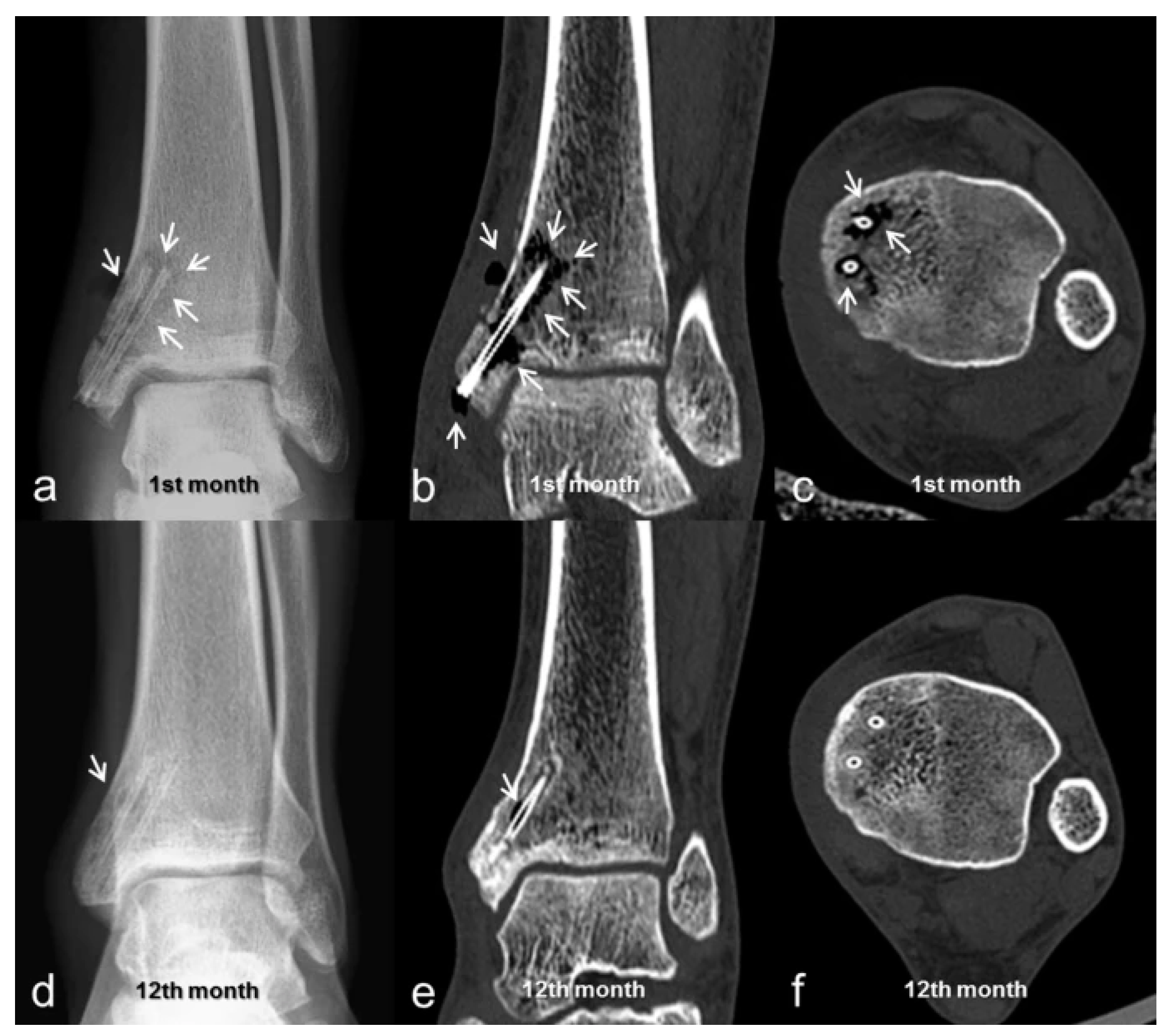
- May, H.; Alper Kati, Y.; Gumussuyu, G.; Yunus Emre, T.; Unal, M.; Kose, O. Bioabsorbable Magnesium Screw versus Conventional Titanium Screw Fixation for Medial Malleolar Fractures. J. Orthop. Traumatol. 2020, 21, 9. [Google Scholar] [CrossRef]
- Zheng, Y.F.; Gu, X.N.; Witte, F. Biodegradable Metals. Mater. Sci. Eng. R Rep. 2014, 77, 1–34. [Google Scholar] [CrossRef]
- Agarwal, S.; Curtin, J.; Duffy, B.; Jaiswal, S. Biodegradable Magnesium Alloys for Orthopaedic Applications: A Review on Corrosion, Biocompatibility and Surface Modifications. Mater. Sci. Eng. C 2016, 68, 948–963. [Google Scholar] [CrossRef]
- Fernandez de Grado, G.; Keller, L.; Idoux-Gillet, Y.; Wagner, Q.; Musset, A.M.; Benkirane-Jessel, N.; Bornert, F.; Offner, D. Bone Substitutes: A Review of Their Characteristics, Clinical Use, and Perspectives for Large Bone Defects Management. J. Tissue Eng. 2018, 9. [Google Scholar] [CrossRef]
- Prakasam, M.; Locs, J.; Salma-Ancane, K.; Loca, D.; Largeteau, A.; Berzina-Cimdina, L. Biodegradable Materials and Metallic Implants-A Review. J. Funct. Biomater. 2017, 8, 44. [Google Scholar] [CrossRef] [PubMed]
- Fine, S.; Hendee, C.F. X-Ray Critical-Absorption and Emission Energies in KeV. Available online: https://www.orteconline.com/-/media/ametekortec/thirdeditionexperiments/library-x-ray_critical_abosrption_and_emission_energies.pdf?la=enLB-tTOfQ (accessed on 29 June 2021).
- Merritt, E.A. X-Ray Absorption Edges. Available online: http://skuld.bmsc.washington.edu/scatter/AS_periodic.html (accessed on 29 June 2021).
- Sykaras, N.; Iacopino, A.M.; Marker, V.A.; Triplett, R.G.; Woody, R.D. Implant Materials, Designs, and Surface Topographies: Their Effect on Osseointegration. A Literature Review. Int. J. Oral Maxillofac. Implant. 2020, 15, 675–690. [Google Scholar]
- Bai, X.L.; Yang, Y.Y.; Chung, T.S.; Ng, S.; Heller, J. Effect of Polymer Compositions on the Fabrication of Poly(Ortho-Ester) Microspheres for Controlled Release of Protein. J. Appl. Polym. Sci. 2001, 80, 1630–1642. [Google Scholar] [CrossRef]
- XL Sci-Tech, Inc. Bioactive Glass Microspheres: 4PiGraft(TM), 45S5, S53P4, 58S, 13-93. Available online: http://xlscitech.com/products/Products-Functional.html (accessed on 29 June 2021).
- Moseke, C.; Gbureck, U. Tetracalcium Phosphate: Synthesis, Properties and Biomedical Applications. Acta Biomater. 2010, 6, 3815–3823. [Google Scholar] [CrossRef] [PubMed]
- PubChem PubChem 2020. Available online: https://pubchem.ncbi.nlm.nih.gov/ (accessed on 29 June 2021).
- CROW A-B Polymer Class Index. Available online: http://www.polymerdatabase.com/home.html (accessed on 29 June 2021).
- Zhang, X. Science and Principles of Biodegradable and Bioresorbable Medical Polymers: Materials and Properties, 1st ed.; Zhang, X., Ed.; Woodhead Publishing: Duxford, UK, 2016; ISBN 9780081003930. [Google Scholar]
- Fromentin, S. The Physics Factbook. In Resistivity of Carbon, Diamond. 2004. Available online: https://hypertextbook.com/facts/ (accessed on 29 June 2021).
- Ward, S.R.; Lieber, R.L. Density and Hydration of Fresh and Fixed Human Skeletal Muscle. J. Biomech. 2005, 38, 2317–2320. [Google Scholar] [CrossRef] [PubMed]
- Farvid, M.S.; Ng, T.W.K.; Chan, D.C.; Barrett, P.H.R.; Watts, G.F. Association of Adiponectin and Resistin with Adipose Tissue Compartments, Insulin Resistance and Dyslipidaemia. Diabetes Obes. Metab. 2005, 7, 406–413. [Google Scholar] [CrossRef] [PubMed]
- Martins, J.A.; Lach, A.A.; Morris, H.L.; Carr, A.J.; Mouthuy, P.-A.A. Polydioxanone Implants: A Systematic Review on Safety and Performance in Patients. J. Biomater. Appl. 2020, 34, 902–916. [Google Scholar] [CrossRef]
- Ketcham, R.A.; Hanna, R.D. Beam Hardening Correction for X-Ray Computed Tomography of Heterogeneous Natural Materials. Comput. Geosci. 2014, 67, 49–61. [Google Scholar] [CrossRef]
- Vedantham, S. Tissue Substitute Materials for Diagnostic X-ray Imaging. In Handbook of X-Ray Imaging: Physics and Technology; Russo, P., Ed.; CRC Press: Boca Raton, FL, USA, 2018; ISBN 9781498741521. [Google Scholar]
- Smeets, R.; Schöllchen, M.; Gauer, T.; Aarabi, G.; Assaf, A.T.; Rendenbach, C.; Beck-Broichsitter, B.; Semmusch, J.; Sedlacik, J.; Heiland, M.; et al. Artefacts in Multimodal Imaging of Titanium, Zirconium and Binary Titanium-Zirconium Alloy Dental Implants: An in Vitro Study. Dentomaxillofacial Radiol. 2017, 46. [Google Scholar] [CrossRef] [PubMed]
- Wellenberg, R.H.H.; Hakvoort, E.T.; Slump, C.H.; Boomsma, M.F.; Maas, M.; Streekstra, G.J. Metal Artifact Reduction Techniques in Musculoskeletal CT-Imaging. Eur. J. Radiol. 2018, 107, 60–69. [Google Scholar] [CrossRef]
- Zhou, P.; Zhang, C.; Gao, Z.; Cai, W.; Yan, D.; Wei, Z. Evaluation of the Quality of CT Images Acquired with Smart Metal Artifact Reduction Software. Open Life Sci. 2018, 13, 155–162. [Google Scholar] [CrossRef] [PubMed]
- Sonnow, L.; Könneker, S.; Vogt, P.M.; Wacker, F.; von Falck, C. Biodegradable Magnesium Herbert Screw—Image Quality and Artifacts with Radiography, CT and MRI. BMC Med. Imaging 2017, 17. [Google Scholar] [CrossRef] [PubMed]
- Goo, H.W.; Goo, J.M. Dual-Energy CT: New Horizon in Medical Imaging. Korean J. Radiol. 2017, 18, 555–569. [Google Scholar] [CrossRef]
- Wellenberg, R.H.H.; Donders, J.C.E.; Kloen, P.; Beenen, L.F.M.; Kleipool, R.P.; Maas, M.; Streekstra, G.J. Exploring Metal Artifact Reduction Using Dual-Energy CT with Pre-Metal and Post-Metal Implant Cadaver Comparison: Are Implant Specific Protocols Needed? Skelet. Radiol. 2018, 47, 839–845. [Google Scholar] [CrossRef]
- Cyteval, C.; Bourdon, A. Imaging Orthopedic Implant Infections. Diagn. Interv. Imaging 2012, 93, 547–557. [Google Scholar] [CrossRef]
- Roth, T.D.; Maertz, N.A.; Andrew Parr, J.; Buckwalter, K.A.; Choplin, R.H. CT of the Hip Prosthesis: Appearance of Components, Fixation, and Complications. Radiographics 2012, 32, 1089–1107. [Google Scholar] [CrossRef]
- Kairemo, K.; Macapinlac, H.A. Sodium Fluoride PET/CT in Clinical Use; Kairemo, K., Macapinlac, H.A., Eds.; Springer International Publishing: Cham. Switzerland, 2020. [Google Scholar]
- Hsu, W.K.; Feeley, B.T.; Krenek, L.; Stout, D.B.; Chatziioannou, A.F.; Lieberman, J.R. The Use of 18F-Fluoride and 18F-FDG PET Scans to Assess Fracture Healing in a Rat Femur Model. Eur. J. Nucl. Med. Mol. Imaging 2007, 34, 1291–1301. [Google Scholar] [CrossRef] [PubMed]
- Brooks, P.C.; Clark, R.A.F.; Cheresh, D.A. Requirement of Vascular Integrin Avβ3 for Angiogenesis. Science 1994, 264, 569–571. [Google Scholar] [CrossRef]
- Haubner, R. Avβ3-Integrin Imaging: A New Approach to Characterise Angiogenesis? Eur. J. Nucl. Med. Mol. Imaging 2006, 33, 54–63. [Google Scholar] [CrossRef] [PubMed]
- Haubner, R.; Maschauer, S.; Prante, O. PET Radiopharmaceuticals for Imaging Integrin Expression: Tracers in Clinical Studies and Recent Developments. BioMed Res. Int. 2014, 2014. [Google Scholar] [CrossRef] [PubMed]
- Rodenberg, E.; Azhdarinia, A.; Lazard, Z.W.; Hall, M.; Kwon, S.K.; Wilganowski, N.; Salisbury, E.A.; Merched-Sauvage, M.; Olmsted-Davis, E.A.; Sevick-Muraca, E.M.; et al. Matrix Metalloproteinase-9 Is a Diagnostic Marker of Heterotopic Ossification in a Murine Model. Tissue Eng. Part A 2011, 17, 2487–2496. [Google Scholar] [CrossRef]
- Toczek, J.; Bordenave, T.; Gona, K.; Kim, H.Y.; Beau, F.; Georgiadis, D.; Correia, I.; Ye, Y.; Razavian, M.; Jung, J.J.; et al. Novel Matrix Metalloproteinase 12 Selective Radiotracers for Vascular Molecular Imaging. J. Med. Chem. 2019, 62, 9743–9752. [Google Scholar] [CrossRef]
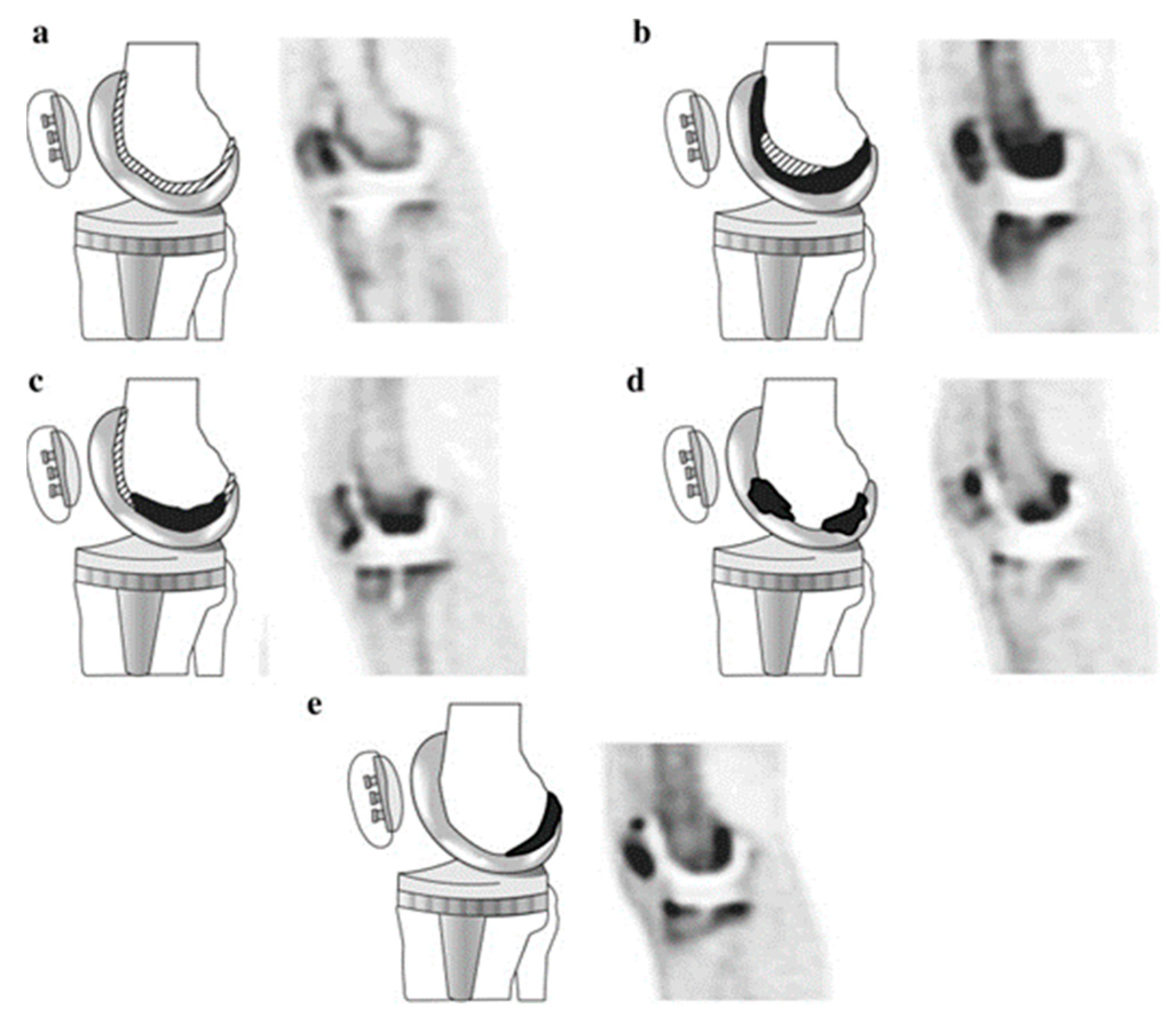
- Son, H.J.; Jeong, Y.J.; Yoon, H.J.; Wang, L.; Kim, H.J.; Park, J.H.; Kang, D.Y. Visual Pattern and Serial Quantitation of 18F-Sodium Fluoride PET/CT in Asymptomatic Patients After Hip and Knee Arthroplasty. Nucl. Med. Mol. Imaging 2016, 50, 308–321. [Google Scholar] [CrossRef]
- Martin, O.; Boos, J.; Aissa, J.; Vay, C.; Heusch, P.; Gaspers, S.; Antke, C.; Sedlmair, M.; Antoch, G.; Schaarschmidt, B.M. Impact of Different Iterative Metal Artifact Reduction (IMAR) Algorithms on PET/CT Attenuation Correction after Port Implementation. Eur. J. Radiol. 2020, 129, 109065. [Google Scholar] [CrossRef] [PubMed]
- Reinert, C.P.; la Fougère, C.; Nikolaou, K.; Pfannenberg, C.; Gatidis, S. Value of CT Iterative Metal Artifact Reduction in PET/CT—Clinical Evaluation in 100 Patients. Br. J. Radiol. 2019, 92, 20180756. [Google Scholar] [CrossRef] [PubMed]
- Guy, C.; Ffytche, D. An Introduction to the Principles of Medical Imaging; Imperial College Press: London, UK, 2000. [Google Scholar]
- ter Haar, G. Ultrasonic Imaging: Safety Considerations. Interface Focus 2011, 1, 686–697. [Google Scholar] [CrossRef] [PubMed]
- Hoppenfeld, S. Treatment and Rehabilitation of Fractures; Lippincott Williams & Wilkins: Philadelphia, PA, USA, 2000; ISBN 9780781721974. [Google Scholar]
- Bhaskar, V.; Chan, H.L.; MacEachern, M.; Kripfgans, O.D. Updates on Ultrasound Research in Implant Dentistry: A Systematic Review of Potential Clinical Indications. Dentomaxillofacial Radiol. 2018, 47, 20180076. [Google Scholar] [CrossRef]
- Tang, S.; Shajudeen, P.; Tasciotti, E.; Righetti, R. Identification of Ultrasound Imaging Markers to Quantify Long Bone Regeneration in a Segmental Tibial Defect Sheep Model in Vivo. Sci. Rep. 2020, 10. [Google Scholar] [CrossRef]
- Steinberg, I.; Huland, D.M.; Vermesh, O.; Frostig, H.E.; Tummers, W.S.; Gambhir, S.S. Photoacoustic Clinical Imaging. Photoacoustics 2019, 14, 77–98. [Google Scholar] [CrossRef]
- Lee, D.; Park, S.; Noh, W.-C.; Im, J.-S.; Kim, C. Photoacoustic Imaging of Dental Implants in a Porcine Jawbone Ex Vivo. Opt. Lett. 2017, 42, 1760. [Google Scholar] [CrossRef]
- Sharma, A.; Srishti; Periyasamy, V.; Pramanik, M. Photoacoustic Imaging Depth Comparison at 532-, 800-, and 1064-Nm Wavelengths: Monte Carlo Simulation and Experimental Validation. J. Biomed. Opt. 2019, 24, 1. [Google Scholar] [CrossRef]
- Burgholzer, P.; Bauer-Marschallinger, J.; Haltmeier, M. Breaking the Resolution Limit in Photoacoustic Imaging Using Non-Negativity and Sparsity. Photoacoustics 2020, 19, 100191. [Google Scholar] [CrossRef]
- Wang, L.V.; Hu, S. Photoacoustic Tomography: In Vivo Imaging from Organelles to Organs. Science 2012, 335, 1458–1462. [Google Scholar] [CrossRef] [PubMed]
- Li, M.; Tang, Y.; Yao, J. Photoacoustic Tomography of Blood Oxygenation: A Mini Review. Photoacoustics 2018, 10, 65–73. [Google Scholar] [CrossRef] [PubMed]
- Berger, A. Magnetic Resonance Imaging. BMJ 2002, 324, 35. [Google Scholar] [CrossRef] [PubMed]
- Anwander, H.; Cron, G.O.; Rakhra, K.; Beaule, P.E. Perfusion MRI in Hips with Metal-on-Metal and Metal-on-Polyethylene Total Hip Arthroplasty: A Pilot Study. Bone Jt. Res. 2016, 5, 73–79. [Google Scholar] [CrossRef]
- Berry, D.B.; Englund, E.K.; Chen, S.; Frank, L.R.; Ward, S.R. Medical Imaging of Tissue Engineering and Regenerative Medicine Constructs. Biomater. Sci. 2021, 9, 301–314. [Google Scholar] [CrossRef] [PubMed]
- Drogset, J.O.; Grøntvedt, T.; Myhr, G. Magnetic Resonance Imaging Analysis of Bioabsorbable Interference Screws Used for Fixation of Bone-Patellar Tendon-Bone Autografts in Endoscopic Reconstruction of the Anterior Cruciate Ligament. Am. J. Sports Med. 2006, 34, 1164–1169. [Google Scholar] [CrossRef]
- Frosch, K.H.; Sawallich, T.; Schütze, G.; Losch, A.; Walde, T.; Balcarek, P.; Konietschke, F.; Stürmer, K.M. Magnetic Resonance Imaging Analysis of the Bioabsorbable MilagroTM Interference Screw for Graft Fixation in Anterior Cruciate Ligament Reconstruction. Strateg. Trauma Limb Reconstr. 2009, 4, 73–79. [Google Scholar] [CrossRef] [PubMed]
- Warden, W.H.; Friedman, R.; Teresi, L.M.; Jackson, D.W. Magnetic Resonance Imaging of Bioabsorbable Polylactic Acid Interference Screws during the First 2 Years after Anterior Cruciate Ligament Reconstruction. Arthrosc. J. Arthrosc. Relat. Surg. 1999, 15, 474–480. [Google Scholar] [CrossRef] [PubMed]
- Kim, Y.H.; Choi, M.; Kim, J.W. Are Titanium Implants Actually Safe for Magnetic Resonance Imaging Examinations? Arch. Plast. Surg. 2019, 46, 96–97. [Google Scholar] [CrossRef]
- Bian, D.; Qin, L.; Lin, W.; Shen, D.; Qi, H.; Shi, X.; Zhang, G.; Liu, H.; Yang, H.; Wang, J.; et al. Magnetic Resonance (MR) Safety and Compatibility of a Novel Iron Bioresorbable Scaffold. Bioact. Mater. 2020, 5, 260–274. [Google Scholar] [CrossRef]
- Fragogeorgi, E.A.; Rouchota, M.; Georgiou, M.; Velez, M.; Bouziotis, P.; Loudos, G. In Vivo Imaging Techniques for Bone Tissue Engineering. J. Tissue Eng. 2019, 10. [Google Scholar] [CrossRef]
- Regelink, J.C.; Raijmakers, P.G.; Bravenboer, N.; Milek, R.; Hoetjes, N.J.; de Kreuk, A.M.; van Duin, M.; Wondergem, M.J.; Lips, P.; Sonneveld, P.; et al. 18F-Fluoride-PET for Dynamic in vivo Monitoring of Bone Formation in Multiple Myeloma. EJNMMI Res. 2016, 6, 46. [Google Scholar] [CrossRef]
- Moran, C.M.; Thomson, A.J.W. Preclinical Ultrasound Imaging—A Review of Techniques and Imaging Applications. Front. Phys. 2020, 8, 124. [Google Scholar] [CrossRef]
- Krishnamoorthy, S.; Blankemeyer, E.; Mollet, P.; Surti, S.; van Holen, R.; Karp, J.S. Performance Evaluation of the MOLECUBES β-CUBE—A High Spatial Resolution and High Sensitivity Small Animal PET Scanner Utilizing Monolithic LYSO Scintillation Detectors. Phys. Med. Biol. 2018, 63, 155013. [Google Scholar] [CrossRef] [PubMed]
- Lin, F.; Shelton, S.E.; Espíndola, D.; Rojas, J.D.; Pinton, G.; Dayton, P.A. 3-D Ultrasound Localization Microscopy for Identifying Microvascular Morphology Features of Tumor Angiogenesis at a Resolution beyond the Diffraction Limit of Conventional Ultrasound. Theranostics 2017, 7, 196–204. [Google Scholar] [CrossRef] [PubMed]
- Linxweiler, J.; Körbel, C.; Müller, A.; Jüngel, E.; Blaheta, R.; Heinzelmann, J.; Stöckle, M.; Junker, K.; Menger, M.D.; Saar, M. Experimental Imaging in Orthotopic Renal Cell Carcinoma Xenograft Models: Comparative Evaluation of High-Resolution 3D Ultrasonography, in-Vivo Micro-CT and 9.4T MRI. Sci. Rep. 2017, 7, 14249. [Google Scholar] [CrossRef]
- Vaidyanathan, S.; Patel, C.N.; Scarsbrook, A.F.; Chowdhury, F.U. FDG PET/CT in Infection and Inflammation—Current and Emerging Clinical Applications. Clin. Radiol. 2015, 70, 787–800. [Google Scholar] [CrossRef] [PubMed]
- Shrestha, B.; Deluna, F.; Anastasio, M.A.; Yong Ye, J.; Brey, E.M. Photoacoustic Imaging in Tissue Engineering and Regenerative Medicine. Tissue Eng. Part B Rev. 2020, 26, 79–102. [Google Scholar] [CrossRef]
- Taha, M.A.; Manske, S.L.; Kristensen, E.; Taiani, J.T.; Krawetz, R.; Wu, Y.; Ponjevic, D.; Matyas, J.R.; Boyd, S.K.; Rancourt, D.E.; et al. Assessment of the Efficacy of MRI for Detection of Changes in Bone Morphology in a Mouse Model of Bone Injury. J. Magn. Reson. Imaging 2013, 38, 231–237. [Google Scholar] [CrossRef]
- Zlotorowicz, M.; Czubak, J.; Kozinski, P.; Boguslawska-Walecka, R. Imaging the Vascularisation of the Femoral Head by CT Angiography. J. Bone Jt. Surgery. Br. Vol. 2012, 94-B, 1176–1179. [Google Scholar] [CrossRef]
- Menichetti, L.; Kusmic, C.; Panetta, D.; Arosio, D.; Petroni, D.; Matteucci, M.; Salvadori, P.A.; Casagrande, C.; L’Abbate, A.; Manzoni, L. MicroPET/CT Imaging of Avβ3 Integrin via a Novel 68Ga-NOTA-RGD Peptidomimetic Conjugate in Rat Myocardial Infarction. Eur. J. Nucl. Med. Mol. Imaging 2013, 40, 1265–1274. [Google Scholar] [CrossRef]
- Siitonen, R.; Peuhu, E.; Autio, A.; Liljenbäck, H.; Mattila, E.; Metsälä, O.; Käkelä, M.; Saanijoki, T.; Dijkgraaf, I.; Jalkanen, S.; et al. 68Ga-DOTA-E[C(RGDFK)]2 PET Imaging of Sharpin-Regulated Integrin Activity in Mice. J. Nucl. Med. 2019, 60, 1380–1387. [Google Scholar] [CrossRef]
- Wang, J.; Qin, B.; Chen, X.; Wagner, W.R.; Villanueva, F.S. Ultrasound Molecular Imaging of Angiogenesis Using Vascular Endothelial Growth Factor-Conjugated Microbubbles. Mol. Pharm. 2017, 14, 781–790. [Google Scholar] [CrossRef]
- Cosgrove, D. Angiogenesis Imaging - Ultrasound. Br. J. Radiol. 2003, 76, S43–S49. [Google Scholar] [CrossRef] [PubMed]
- Woloszyk, A.; Wolint, P.; Becker, A.S.; Boss, A.; Fath, W.; Tian, Y.; Hoerstrup, S.P.; Buschmann, J.; Emmert, M.Y. Novel Multimodal MRI and MicroCT Imaging Approach to Quantify Angiogenesis and 3D Vascular Architecture of Biomaterials. Sci. Rep. 2019, 9. [Google Scholar] [CrossRef] [PubMed]
- Pietikäinen, M.K. Texture Analysis in Machine Vision; Series in Machine Perception and Artificial Intelligence; WORLD SCIENTIFIC: Singapore, 2000; Volume 40, ISBN 978-981-02-4373-9. [Google Scholar]
- Ahmadvand, A.; Reza Daliri, M. A Review on Texture Analysis Methods in Biomedical Image Processing. OMICS J. Radiol. 2016, 5. [Google Scholar] [CrossRef]
- Ayyad, S.M.; Shehata, M.; Shalaby, A.; Abou El-Ghar, M.; Ghazal, M.; El-Melegy, M.; Abdel-Hamid, N.B.; Labib, L.M.; Ali, H.A.; El-Baz, A. Role of Ai and Histopathological Images in Detecting Prostate Cancer: A Survey. Sensors 2021, 21, 2586. [Google Scholar] [CrossRef]
- Andrearczyk, V.; Whelan, P.F. Using Filter Banks in Convolutional Neural Networks for Texture Classification. Pattern Recognit. Lett. 2016, 84, 63–69. [Google Scholar] [CrossRef]
- Lundervold, A.S.; Lundervold, A. An Overview of Deep Learning in Medical Imaging Focusing on MRI. Z. Med. Phys. 2019, 29, 102–127. [Google Scholar] [CrossRef]


| Main Atoms | Density | ||
|---|---|---|---|
| Ceramics | |||
| Calcium phosphates | |||
| Hydroxyapatite | Ca, P | 3.1–3.2 | |
| Dicalcium phosphate dihydrate | DCPD | Ca, P | 2.3 |
| Brushite | Ca, P | 2.3–2.33 | |
| Tricalcium phosphate | TCP | Ca, P | 3 |
| Tetracalcium phosphate | TeCP | Ca, P | 3.06 |
| Bioglass | Si, Ca, Na, O | 2.6–2.7 | |
| Polymers | |||
| Poly(amino acids) | e.g., poly(γ-benzyl-L-glutamate) | C, H | 1.2 |
| Poly(ortho esters) | C, O, H | 0.39–0.46 | |
| Polyphosphazenes | P, N | ||
| Poly(propylene fumarate) | C, O | 0.998 | |
| Polyesters | |||
| Aliphatic | Polylactide | C, H, O | 1.25–1.27 |
| Polyglycolide | C, H, O | 1.5–1.6 | |
| Copolymers | |||
| Polyhydroxy- alkanoates | Polyhydroxy- butyrate | C, H, O | 1.18–1.26 |
| Polyhydroxy- valerate | C, H, O | ||
| Polyhydroxy- hexanoate | C, H, O | ||
| Polyhydroxy- octanoate | C, H, O | ||
| Copolymers | |||
| Polycaprolactone | C, H, O | 1.10–1.15 | |
| Polydioxanone | C, O | 1.318 | |
| Metals | |||
| Magnesium | Alloyed with Ca, Zn, Al, rare metals | Mg | 1.738 |
| Iron | Fe | 7.874 | |
| Zinc | Zn | 7.140 | |
| Body tissues | |||
| Bone (cortical) | 1.9 | ||
| Muscle (skeletal) | 1.06 |
| Photon Energy (keV) | Mg | Ti | Hydroxyapatite | Cortical Bone | Skeletal Muscle |
|---|---|---|---|---|---|
| 5 | 273.21 | 3073.09 | 967.20 | 350.59 | 44.08 |
| 6 | 161.41 | 1941.18 | 593.03 | 213.70 | 25.47 |
| 7.112 | 15.23 | ||||
| 7.112 | 15.25 | ||||
| 8 | 69.36 | 906.61 | 270.07 | 96.65 | 10.67 |
| 9.659 | 56.85 | 6.03 | |||
| 9.659 | 56.89 | 6.04 | |||
| 10 | 35.70 | 494.76 | 144.49 | 51.53 | 5.44 |
| 15 | 10.55 | 159.02 | 45.20 | 16.10 | 1.65 |
| 20 | 4.48 | 69.62 | 19.59 | 7.03 | 0.78 |
| 30 | 1.44 | 21.42 | 6.11 | 2.29 | 0.35 |
| 40 | 0.74 | 9.35 | 2.81 | 1.13 | 0.25 |
| 50 | 0.50 | 5.04 | 1.65 | 0.72 | 0.22 |
| 60 | 0.39 | 3.14 | 1.13 | 0.54 | 0.20 |
| 80 | 0.31 | 1.63 | 0.73 | 0.39 | 0.18 |
| 100 | 0.27 | 1.10 | 0.58 | 0.34 | 0.17 |
| 120 | 0.25 | 0.86 | 0.50 | 0.31 | 0.16 |
| 140 | 0.24 | 0.73 | 0.46 | 0.28 | 0.16 |
| 150 | 0.23 | 0.68 | 0.44 | 0.28 | 0.15 |
| Type | Material | Attenuation Coefficient at 511 keV |
|---|---|---|
| Metals | Mg | 0.15 |
| Fe | 0.64 | |
| Zn | 0.58 | |
| Ti | 0.36 | |
| Ceramics | Hydroxy- apatite | 0.27 |
| DCPD | 0.20 | |
| Brushite | 0.21 | |
| TCP | 0.27 | |
| TeCP | 0.27 | |
| Bioglass | 0.23 | |
| Polymers | poly(γ-benzyl-L-glutamate) | 0.11 |
| Polypropylene fumarate | 0.11 | |
| Polylactide | 0.11 | |
| Poly- glycolide | 0.14 | |
| Polyhydroxy-butyrate | 0.11 | |
| Polyhydroxy-valerate | 0.11 | |
| Polycapro- lactone | 0.11 | |
| Poly- dioxanone | 0.12 | |
| Tissues | Cortical bone | 0.17 |
| Skeletal muscle | 0.10 |
| CT | PET | US | PAI | MRI | |
|---|---|---|---|---|---|
| Depth | - [72] | - [72] | >50 mm [74] | >50 mm [60] | - |
| Spatial resolution | 0.05 mm [75] | 1–2 mm [72] | Up to 0.15 mm at 25 MHz [76] | 1/200th of depth [60,61] | >0.1 mm [77] |
| Target | |||||
| Bone tissue | Implants and tissues of different attenuation | Molecular activity with target tracers | Surface topography | Surface topography | Unsuitable |
| Soft tissues | Molecular activity with target tracers | Structures and borders | Structures and molecular chromophores | Highly efficient | |
| Implant | Surface topography | Mostly surface topography | Unsuitable | ||
| Biomarkers | |||||
| Inflammation | Visual oedema and liquid accumulation, liquid iodine contrast [41] | e.g., 18F-FDG [78] | Visual oedema and liquid accumulation | Oxygen level dynamics [79] | Visual oedema and liquid accumulation |
| Bone healing | Visual changes | e.g., 18F-NaF [44, 72.73] | Exceptional for early ossification [57] | Chromophores; tissue morphology changes during remodelling | Contrast of low signal from bone with high signal from soft tissues [80] |
| Angiogenesis | blood vessels with iodine contrast [81] | e.g., 68Ga-NODAGA-RGD [47]; 68Ga-NOTA-RGD [47,82]; 68Ga-DOTA-E[c(RGDfK)]2 [83] | Vascular imaging using microbubbles and binding agents [84,85] | Integrin-binding chromophores; blood oxygenation | e.g., Gadolinium contrast, perfusion capacity [86] |
| Advantages | Simple, fast | Large choice of radiotracers for different targets, possible to design tracers for specific targets; metabolic data | Simple; non-invasive; no contraindications | Can image molecular activity; differentiate targets based on absorption spectra | High resolution and depth; very good soft tissue differentiation; possible to use contrast agents |
| Disadvantages | Radiation; requires high attenuation between target and surroundings; contrast agents require injections; implant artefacts [35,36,37,40,78] | Radiation; high price; complexity; injections; long duration; requires either in-house isotope production and tracer laboratory or be within transportation range | Limited depth; can’t image inside hard objects | Very limited depth; light absorption; complexity; exogenous contrast agents require injections | High price; complexity; unsuitable for ferromagnetic implants [35]; poor imaging of targets lacking H+ protons; better resolution requires longer imaging time; contrast agents are injected |
Publisher’s Note: MDPI stays neutral with regard to jurisdictional claims in published maps and institutional affiliations. |
© 2021 by the authors. Licensee MDPI, Basel, Switzerland. This article is an open access article distributed under the terms and conditions of the Creative Commons Attribution (CC BY) license (https://creativecommons.org/licenses/by/4.0/).
Share and Cite
Riehakainen, L.; Cavallini, C.; Armanetti, P.; Panetta, D.; Caramella, D.; Menichetti, L. In Vivo Imaging of Biodegradable Implants and Related Tissue Biomarkers. Polymers 2021, 13, 2348. https://doi.org/10.3390/polym13142348
Riehakainen L, Cavallini C, Armanetti P, Panetta D, Caramella D, Menichetti L. In Vivo Imaging of Biodegradable Implants and Related Tissue Biomarkers. Polymers. 2021; 13(14):2348. https://doi.org/10.3390/polym13142348
Chicago/Turabian StyleRiehakainen, Leon, Chiara Cavallini, Paolo Armanetti, Daniele Panetta, Davide Caramella, and Luca Menichetti. 2021. "In Vivo Imaging of Biodegradable Implants and Related Tissue Biomarkers" Polymers 13, no. 14: 2348. https://doi.org/10.3390/polym13142348
APA StyleRiehakainen, L., Cavallini, C., Armanetti, P., Panetta, D., Caramella, D., & Menichetti, L. (2021). In Vivo Imaging of Biodegradable Implants and Related Tissue Biomarkers. Polymers, 13(14), 2348. https://doi.org/10.3390/polym13142348