
Simple Preparation of Polydimethylsiloxane and Polyurethane Blend Film for Marine Antibiofouling Application

 ,
,  and
and
Abstract
:
1. Introduction
2. Materials and Methods
2.1. Material and Chemicals
2.2. Preparation of the Polymer Blend
2.3. Characterization of the Polymer Blend
2.3.1. Scanning Electron Microscope (SEM)
2.3.2. Fourier Transform Infrared Spectra (ATR-FTIR)
2.3.3. Contact Angle Measurement
2.3.4. Mechanical Test (LLOYD)
2.3.5. Atomic Force Microscopic (AFM)
2.3.6. Swelling Test
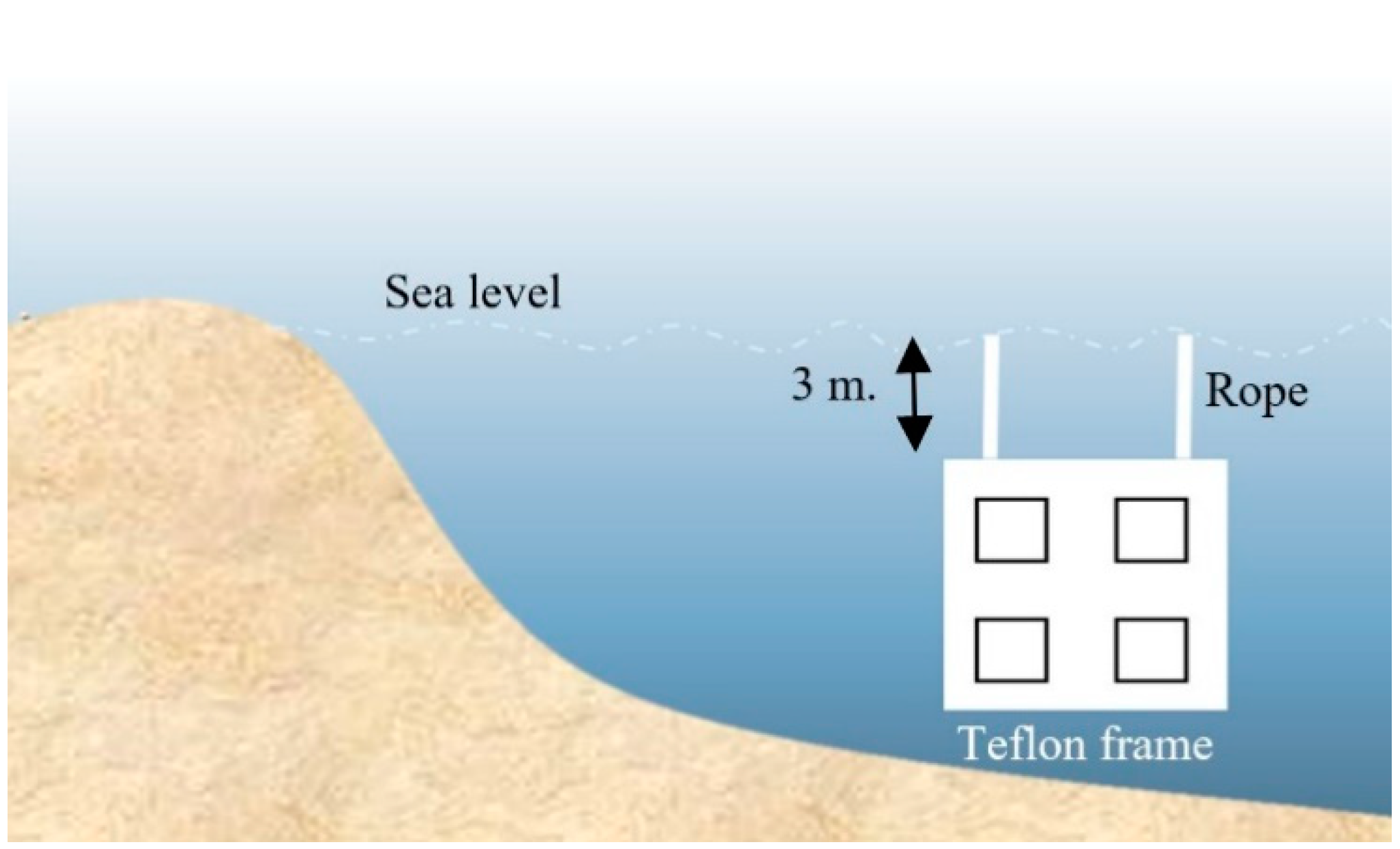
2.3.7. Microfouling Analysis
3. Results
3.1. Characteristics of PDMS:PU Blend Film
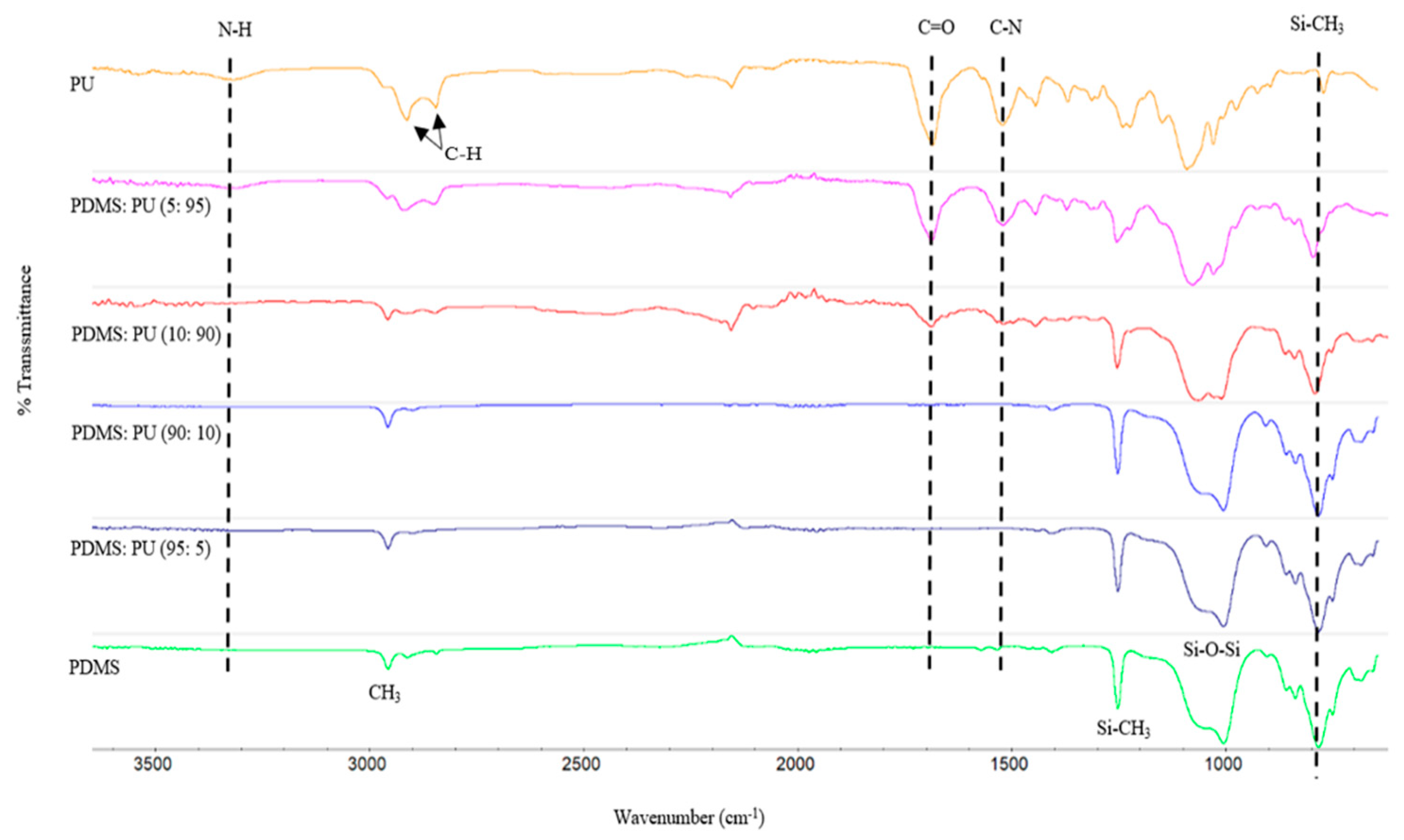
3.1.1. FTIR Spectral of PDMS:PU Blend Film
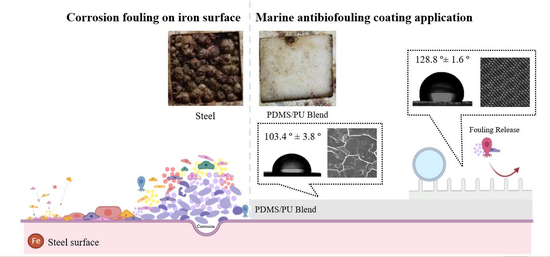
3.1.2. Water Contact Angle (WCA) of PDMS:PU Blend Film
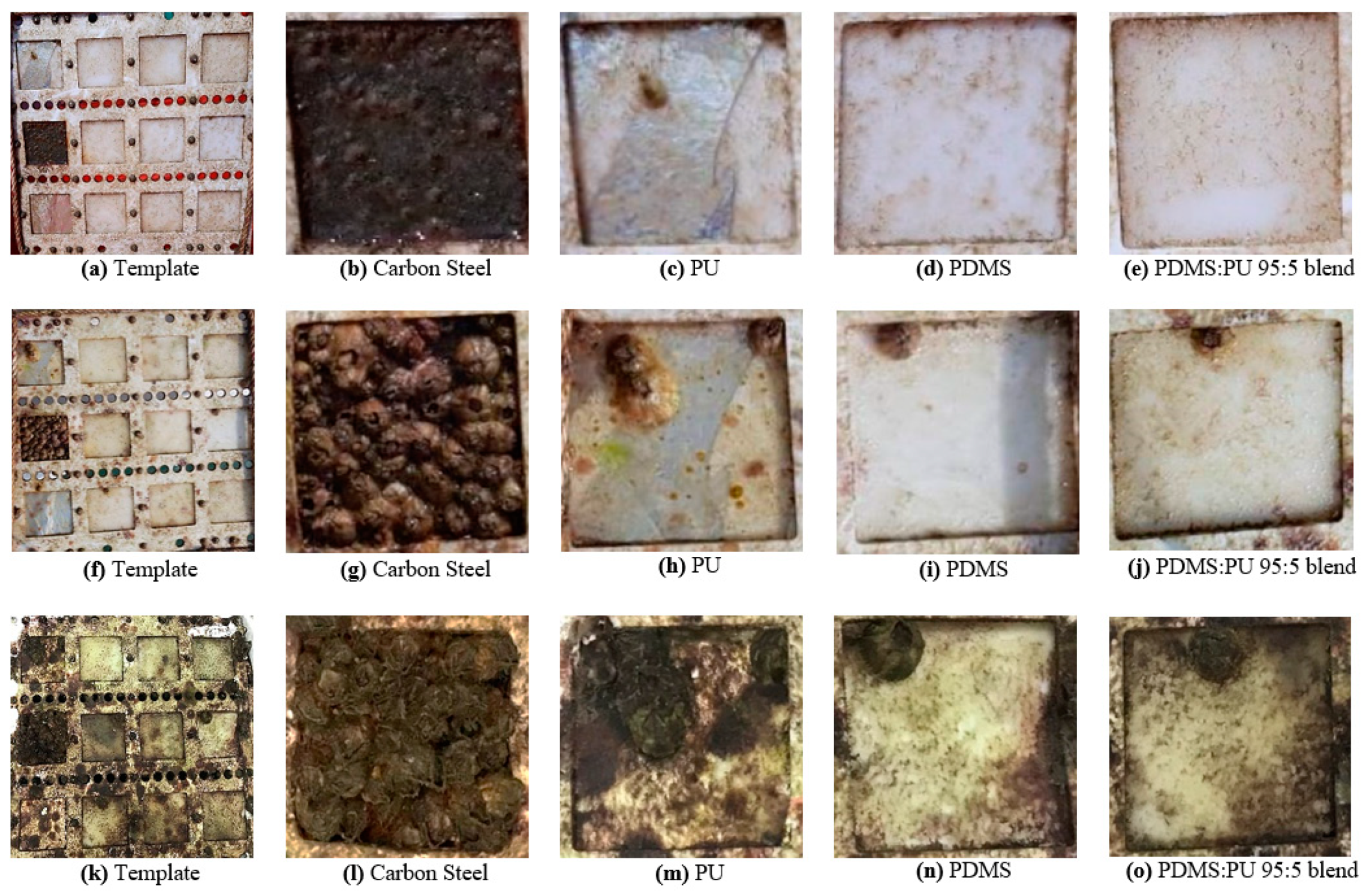
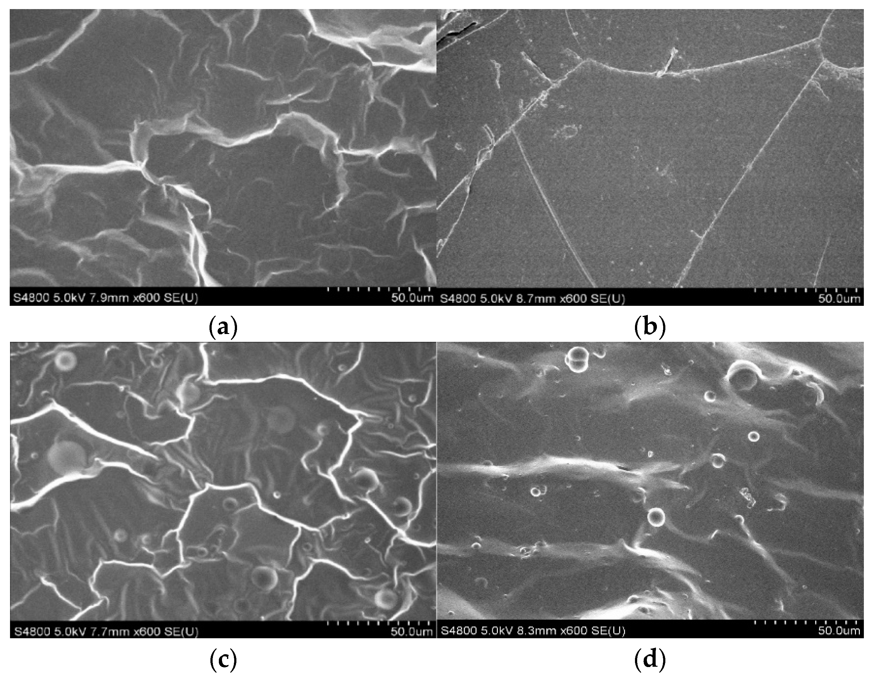
3.1.3. Morphology of the Polymer Blend Film
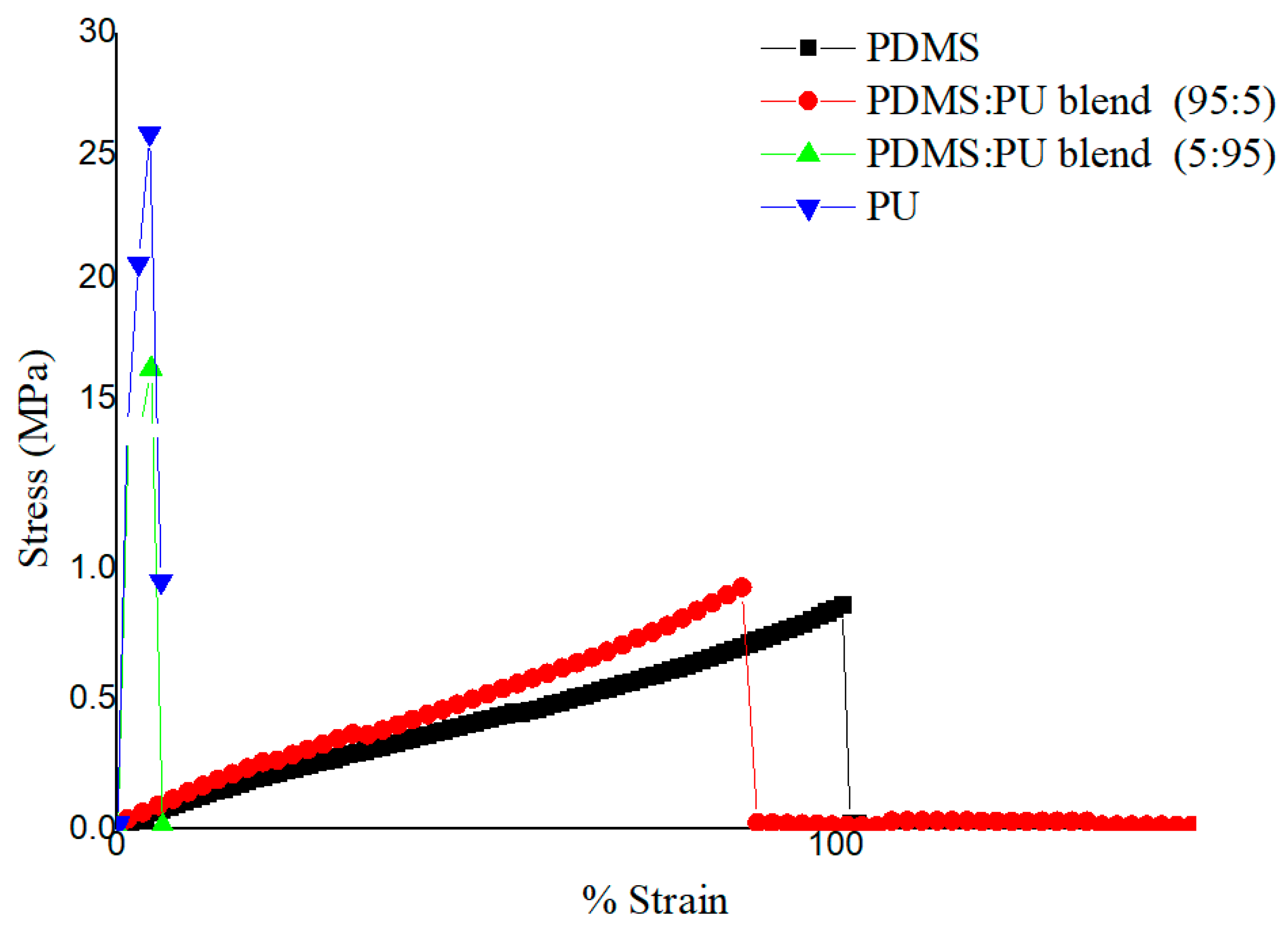
3.1.4. Mechanical Properties Studies of the PDMS:PU Blend Film
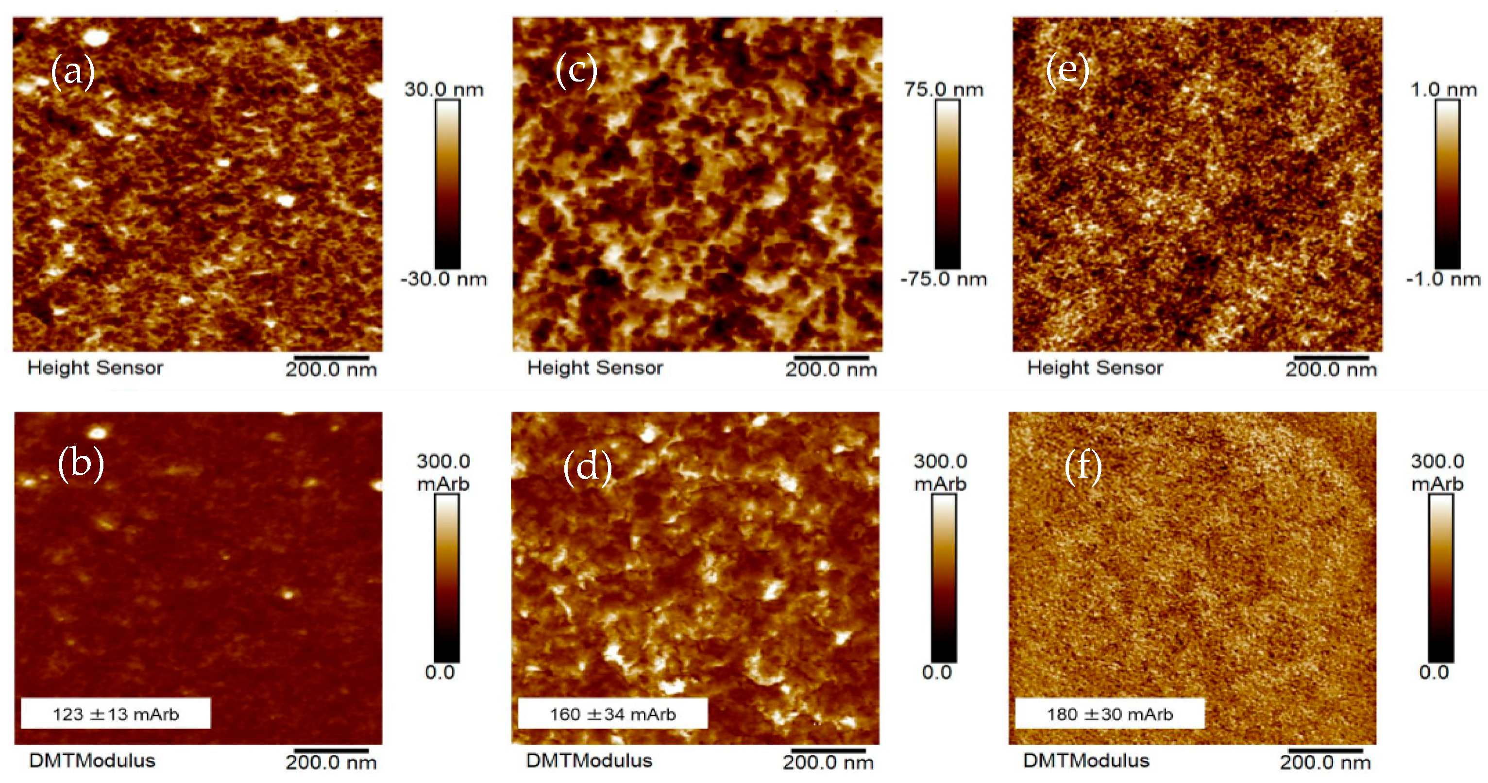
3.1.5. Atomic Force Microscopic (AFM) Studies
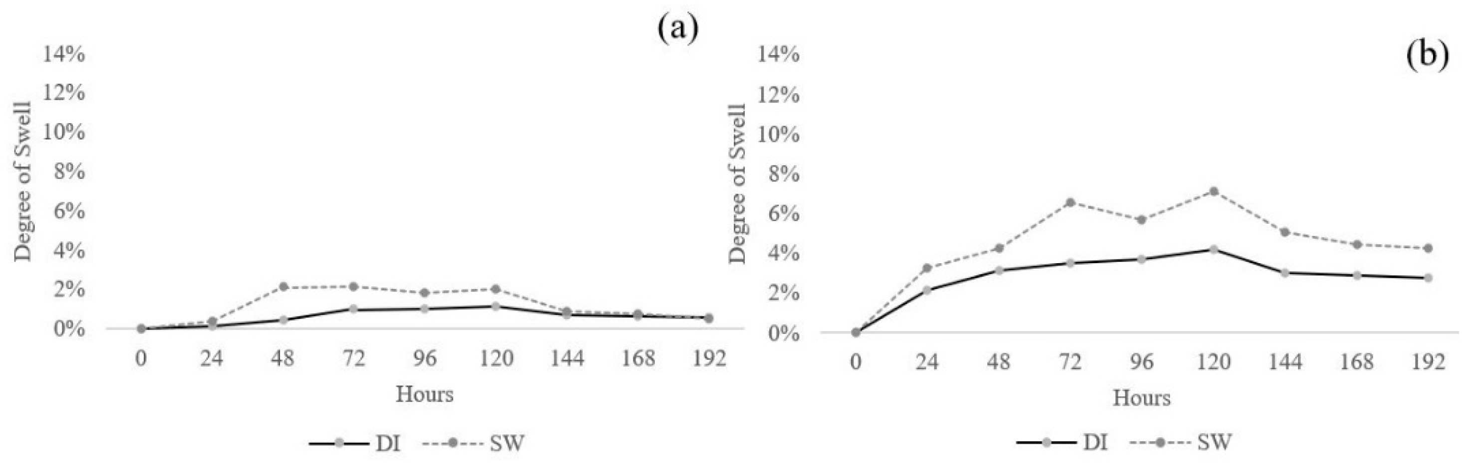
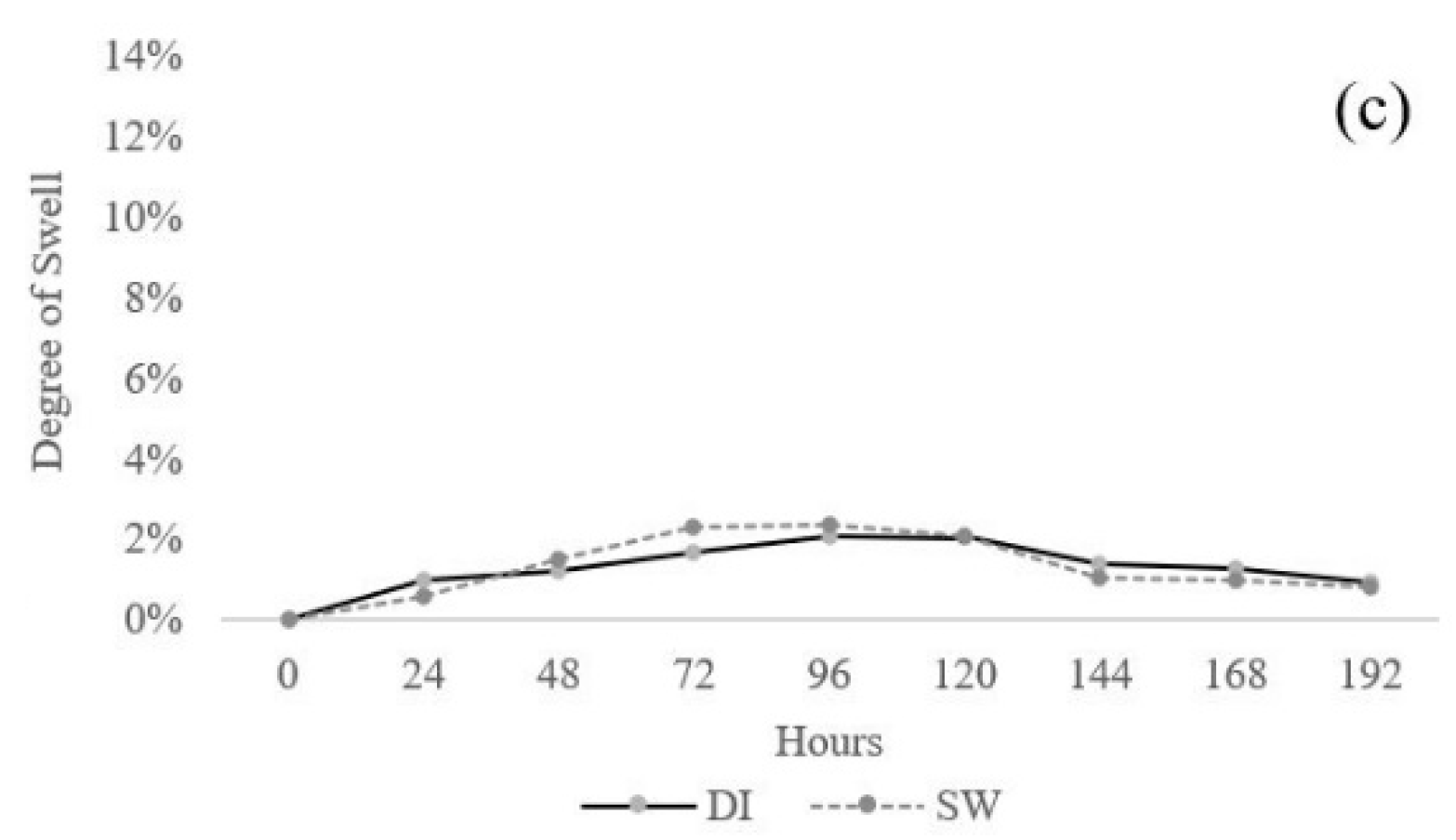
3.1.6. Effect of Swelling
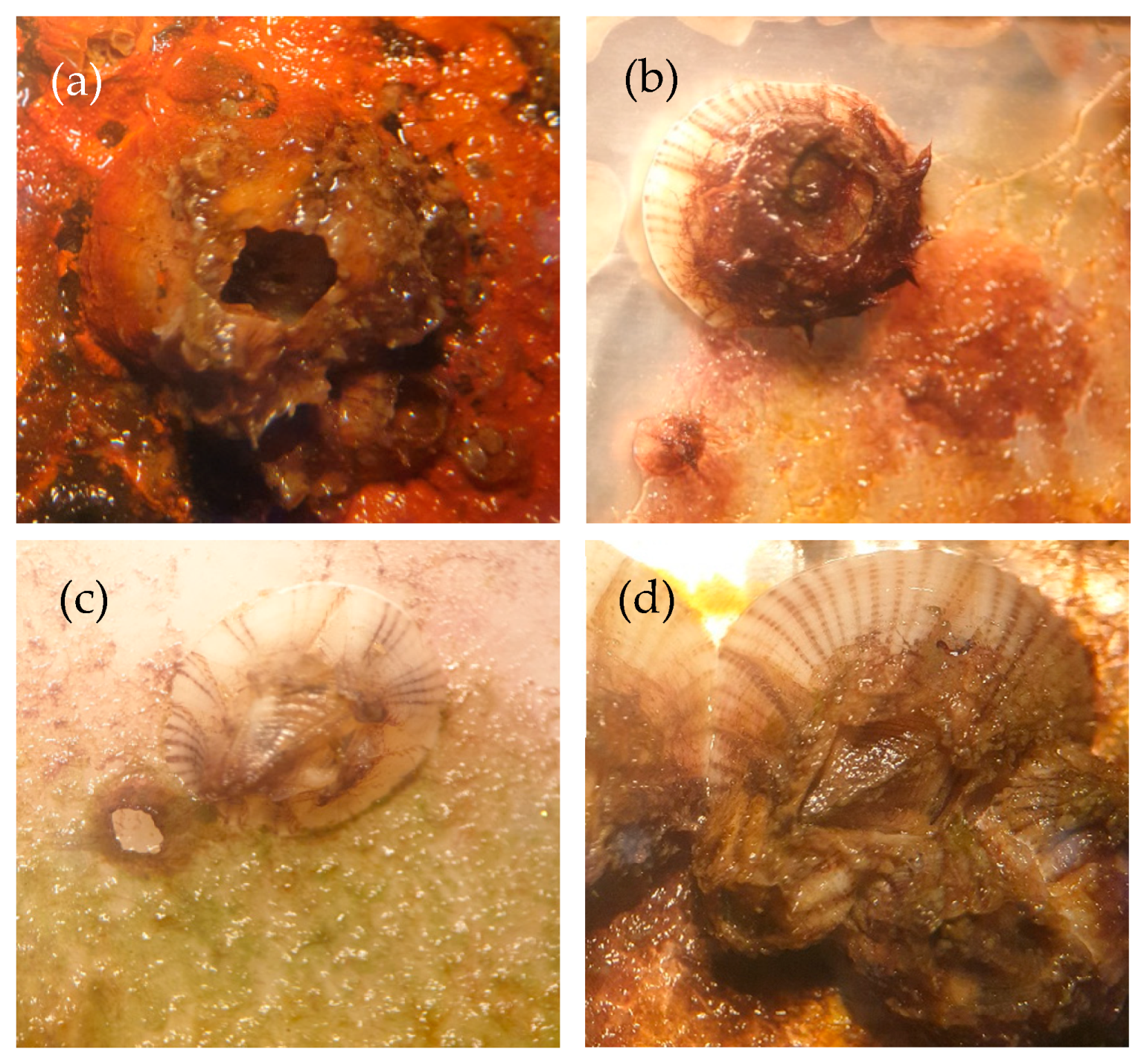
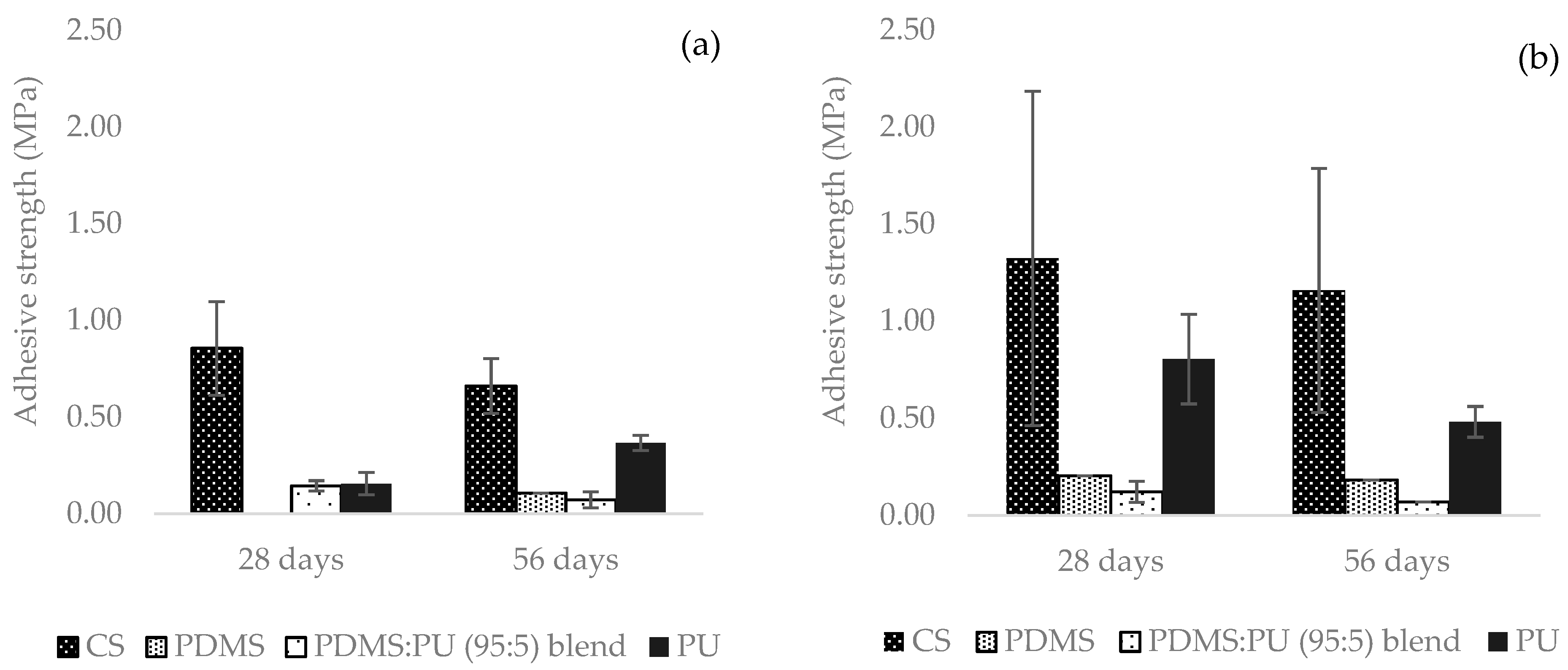
3.1.7. Barnacle Measurements
3.2. Characteristics of PDMS:PU Blend Film with Micro Patterning Fabricated by Soft Lithography
3.2.1. Morphology of PDMS:PU Blend Film with Micro Pattering Fabricated by Soft Lithography
3.2.2. Water Contact Angle (WCA) of Polymer Blend with Micro Patterning Fabricated by Soft Lithography
4. Conclusions
Author Contributions
Funding
Institutional Review Board Statement
Informed Consent Statement
Acknowledgments
Conflicts of Interest
References
- Farkas, A.; Song, S.; Degiuli, N.; Martić, I.; Demirel, Y.K. Impact of biofilm on the ship propulsion characteristics and the speed reduction. Ocean Eng. 2020, 199, 107033. [Google Scholar] [CrossRef]
- Dharmlingam, S. Biofouling-Bioadhesion of Micro-Organisms and Its Prevention: A Review. IJERR 2018, 11–21. [Google Scholar]
- Yebra, D.M.; Kiil, S.; Dam-Johansen, K. Antifouling technology—Past, present and future steps towards efficient and environmentally friendly antifouling coatings. Prog. Org. Coat. 2004, 50, 75–104. [Google Scholar] [CrossRef]
- Simões, M. Antimicrobial strategies effective against infectious bacterial biofilms. Curr. Med. Chem. 2011, 18, 2129–2145. [Google Scholar] [CrossRef]
- Yi, J.; Huang, C.; Zhuang, H.; Gong, H.; Zhang, C.; Ren, R.; Ma, Y. Degradable polyurethane based on star-shaped polyester polyols (trimethylolpropane and ɛ-caprolactone) for marine antifouling. Prog. Org. Coat. 2015, 87, 161–170. [Google Scholar] [CrossRef]
- Anthony Yesudass, S.; Mohanty, S.; Nayak, S.K.; Rath, C.C. Zwitterionic–polyurethane coatings for non-specific marine bacterial inhibition: A nontoxic approach for marine application. Eur. Polym. J. 2017, 96, 304–315. [Google Scholar] [CrossRef]
- Hu, W.; Culloty, S.; Darmody, G.; Lynch, S.; Davenport, J.; Ramirez-Garcia, S.; Dawson, K.A.; Lynch, I.; Blasco, J.; Sheehan, D. Toxicity of copper oxide nanoparticles in the blue mussel, Mytilus edulis: A redox proteomic investigation. Chemosphere 2014, 108, 289–299. [Google Scholar] [CrossRef] [Green Version]
- Gomes, T.; Pereira, C.G.; Cardoso, C.; Pinheiro, J.P.; Cancio, I.; Bebianno, M.J. Accumulation and toxicity of copper oxide nanoparticles in the digestive gland of Mytilus galloprovincialis. Aquat. Toxicol. 2012, 118–119, 72–79. [Google Scholar] [CrossRef] [PubMed]
- Nurioglu, A.G.; Esteves, A.C.C.; de With, G. Non-toxic, non-biocide-release antifouling coatings based on molecular structure design for marine applications. J. Mater. Chem. B 2015, 3, 6547–6570. [Google Scholar] [CrossRef] [Green Version]
- Sokolova, A.; Cilz, N.; Daniels, J.; Stafslien, S.J.; Brewer, L.H.; Wendt, D.E.; Bright, F.V.; Detty, M.R. A comparison of the antifouling/foul-release characteristics of non-biocidal xerogel and commercial coatings toward micro- and macrofouling organisms. Biofouling 2012, 28, 511–523. [Google Scholar] [CrossRef] [Green Version]
- Zalewski, K.; Chyłek, Z.; Trzciński, W.A. A Review of Polysiloxanes in Terms of Their Application in Explosives. Polymers 2021, 13, 1080. [Google Scholar] [CrossRef]
- Pérez, E.; Contreras-Lopez, D.; Vallejo, J.; Gonzalez-Calderon, J.A. Polysiloxanes as polymer matrices in biomedical engineering: Their interesting properties as the reason for the use in medical sciences. Polym. Bull. 2020, 77. [Google Scholar] [CrossRef]
- Vinckier, I.; Moldenaers, P.; Mewis, J. Relationship between Rheology and Morphology of Model Blends in Steady Shear Flow. J. Rheol. 1996, 40, 613–631. [Google Scholar] [CrossRef]
- Cui, X.; Zhu, G.; Pan, Y.; Shao, Q.; Zhao, C.; Dong, M.; Zhang, Y.; Guo, Z. Polydimethylsiloxane-titania nanocomposite coating: Fabrication and corrosion resistance. Polymer 2018, 138, 203–210. [Google Scholar] [CrossRef]
- Thanakhun, K.; Puttapitukporn, T. PDMS Material Models for Anti-fouling Surfaces Using Finite Element Method. Eng. J. 2019, 23, 381–398. [Google Scholar] [CrossRef]
- Yun, X.; Xiong, Z.; He, Y.; Wang, X. Superhydrophobic lotus-leaf-like surface made from reduced graphene oxide through soft-lithographic duplication. RSC Adv. 2020, 10, 5478–5486. [Google Scholar] [CrossRef]
- Placet, V.; Delobelle, P. Mechanical properties of bulk polydimethylsiloxane for microfluidics over a large range of frequencies and aging times. J. Micromech. Microeng. 2015, 25, 035009. [Google Scholar] [CrossRef]
- Weibel, D.B.; Diluzio, W.R.; Whitesides, G.M. Microfabrication meets microbiology. Nat. Rev. Microbiol. 2007, 5, 209–218. [Google Scholar] [CrossRef] [PubMed]
- Kim, M.; Moon, B.-U.; Hidrovo, C.H. Enhancement of the thermo-mechanical properties of PDMS molds for the hot embossing of PMMA microfluidic devices. J. Micromech. Microeng. 2013, 23, 095024. [Google Scholar] [CrossRef] [Green Version]
- Wang, Z.; Volinsky, A.A.; Gallant, N.D. Crosslinking effect on polydimethylsiloxane elastic modulus measured by custom-built compression instrument. J. Appl. Polym. Sci. 2014, 131. [Google Scholar] [CrossRef] [Green Version]
- Ibrahim, I.A.M.; Zikry, A.A.F.; Sharaf, M.A.; Mark, J.E.; Jacob, K.; Jasiuk, I.M.; Tannenbaumn, R. Elastic behavior of silica/poly(dimethylsiloxane) nanocomposites: Nano-size effects. IOP Conf. Ser. Mater. Sci. Eng. 2012, 40, 012008. [Google Scholar] [CrossRef] [Green Version]
- Hasan, A.M.A.; Abdel-Raouf, M.E.-S. Cellulose-Based Superabsorbent Hydrogels. In Cellulose-Based Superabsorbent Hydrogels; Mondal, M.I.H., Ed.; Springer International Publishing: Cham, Switzerland, 2019; pp. 245–267. [Google Scholar]
- Damrongsakkul, S.; Sinweeruthai, R.; Higgins, J. Processability and chemical resistance of the polymer blend of thermoplastic polyurethane and polydimethylsiloxane. Macromol. Symp. 2003, 198, 411–420. [Google Scholar] [CrossRef]
- Atthi, N.; Sripumkhai, W.; Pattamang, P.; Thongsook, O.; Srihapat, A.; Meananeatra, R.; Supadech, J.; Klunngien, N.; Jeamsaksiri, W. Fabrication of robust PDMS micro-structure with hydrophobic properties. Microelectron. Eng. 2020, 224, 111255. [Google Scholar] [CrossRef]
- Wu, Z.; Wang, H.; Tian, X.; Cui, P.; Ding, X.; Ye, X. The effects of polydimethylsiloxane on transparent and hydrophobic waterborne polyurethane coatings containing polydimethylsiloxane. Phys. Chem. Chem. Phys. 2014, 16, 6787–6794. [Google Scholar] [CrossRef]
- Boya, R.; Kulkarni, G. Micromolding—A Soft Lithography Technique; Micromanufacturing Processes: Boca Raton, FL, USA, 2012; pp. 329–347. [Google Scholar]
- Vinagre, P.A.; Simas, T.; Cruz, E.; Pinori, E.; Svenson, J. Marine Biofouling: A European Database for the Marine Renewable Energy Sector. J. Mar. Sci. Eng. 2020, 8. 495. [Google Scholar] [CrossRef]
- Luo, S.-J.; Su, Y.-H.; Lu, M.-J.; Kuo, J.-C. EBSD analysis of magnesium addition on inclusion formation in SS400 structural steel. Mater. Charact. 2013, 82, 103–112. [Google Scholar] [CrossRef]
- Chieng, B.W.; Ibrahim, N.A.; Ahmad Daud, N.; Talib, Z.A. Chapter 8—Functionalization of Graphene Oxide via Gamma-Ray Irradiation for Hydrophobic Materials. In Synthesis, Technology and Applications of Carbon Nanomaterials; Elsevier: Amsterdam, The Netherlands, 2019; pp. 177–203. [Google Scholar] [CrossRef]
- Kojio, K.; Mitsui, Y.; Furukawa, M. Synthesis and properties of highly hydrophilic polyurethane based on diisocyanate with ether group. Polymer 2009, 50. [Google Scholar] [CrossRef] [Green Version]
- Mouritz, A.P. (Ed.) 1—Introduction to aerospace materials: In Introduction to Aerospace Materials; Woodhead Publishing: Cambridge, UK, 2012; pp. 1–14. [Google Scholar] [CrossRef]
- Dai, Z.; Yang, K.; Dong, Q. Mechanical, Thermal and Morphology Properties of Thermoplastic Polyurethane Copolymers Incorporating α,ω-Dihydroxy-[poly(propyleneoxide)-poly (dimethylsiloxane)-poly(propyleneoxide)] of Varying Poly(propyleneoxide) Molecular Weight. Open J. Synth. Theory Appl. 2015, 4, 41–57. [Google Scholar] [CrossRef] [Green Version]
- Zhu, R.; Wang, X.; Yang, J.; Wang, Y.; Zhang, Z.; Hou, Y.; Lin, F. Influence of hydroxyl-terminated polydimethylsiloxane on high-strength biocompatible polycarbonate urethane films. Biomed. Mater. 2016, 12, 015011. [Google Scholar] [CrossRef]
- Magonov, S.N. Atomic Force Microscopy in Analysis of Polymers. Encycl. Anal. Chem. Appl. Theory Instrum. 2006. [Google Scholar] [CrossRef]
- Ouyang, L.; Kuo, C.-c.; Farrell, B.; Pathak, S.; Wei, B.; Qu, J.; Martin, D.C. Poly[3,4-ethylene dioxythiophene (EDOT)-co-1,3,5-tri[2-(3,4-ethylene dioxythienyl)]-benzene (EPh)] copolymers (PEDOT-co-EPh): Optical, electrochemical and mechanical properties. J. Mater. Chem. B 2015, 3, 5010–5020. [Google Scholar] [CrossRef]
- Mayasari, H.E.; Setyadewi, N.M. Thermogravimetry and swelling characteristics af NBR/EPDM blends with some compatibilizers. AIP Conf. Proc. 2018, 2049, 020042. [Google Scholar] [CrossRef]
- Ma, C.; Zhang, W.; Zhang, G.; Qian, P.-Y. Environmentally Friendly Antifouling Coatings Based on Biodegradable Polymer and Natural Antifoulant. ACS Sustain. Chem. Eng. 2017, 5, 6304–6309. [Google Scholar] [CrossRef]
- Pathak, V.M.; Navneet. Review on the current status of polymer degradation. A microbial approach. Bioresour. Bioprocess. 2017, 4, 15. [Google Scholar] [CrossRef]
- Ba, M.; Zhang, Z.; Qi, Y. Fouling Release Coatings Based on Polydimethylsiloxane with the Incorporation of Phenylmethylsilicone Oil. Coatings 2018, 8, 153. [Google Scholar] [CrossRef] [Green Version]
- Finlay, J.A.; Bennett, S.M.; Brewer, L.H.; Sokolova, A.; Clay, G.; Gunari, N.; Meyer, A.E.; Walker, G.C.; Wendt, D.E.; Callow, M.E.; et al. Barnacle settlement and the adhesion of protein and diatom microfouling to xerogel films with varying surface energy and water wettability. Biofouling 2010, 26, 657–666. [Google Scholar] [CrossRef]


| Polyurethane | PDMS:PU blend (5:95) | PDMS:PU blend (10:90) |
 86.9° ± 3.2° | 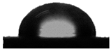 91.4° ± 0.8° | 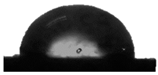 92.2° ± 2.5° |
| PDMS:PU blend (90:10) | PDMS:PU blend (95:5) | Polydimethylsiloxane |
 94.6° ± 0.8° |  103.4° ± 3.8° |  109.5° ± 4.2° |
| Element | Polydimethylsiloxane | PDMS:PU Blend (95:5) | Polyurethane | |||||
|---|---|---|---|---|---|---|---|---|
| Weight% | Atomic | Weight% | Atomic | Weight% | Atomic | |||
| C | 24.30 | 38.82 | 53.47 | 68.58 | 66.05 | 72.16 | ||
| O | 18.35 | 22.00 | 14.24 | 13.72 | 33.95 | 27.84 | ||
| Si | 57.35 | 39.18 | 32.29 | 17.71 | 0 | 0 | ||
| PDMS:PU blend (95:5) | PDMS:PU blend (95:5) sharklet pattern |
 103.4° ± 3.8° |  128.8° ± 1.6° |
Publisher’s Note: MDPI stays neutral with regard to jurisdictional claims in published maps and institutional affiliations. |
© 2021 by the authors. Licensee MDPI, Basel, Switzerland. This article is an open access article distributed under the terms and conditions of the Creative Commons Attribution (CC BY) license (https://creativecommons.org/licenses/by/4.0/).
Share and Cite
Chungprempree, J.; Charoenpongpool, S.; Preechawong, J.; Atthi, N.; Nithitanakul, M. Simple Preparation of Polydimethylsiloxane and Polyurethane Blend Film for Marine Antibiofouling Application. Polymers 2021, 13, 2242. https://doi.org/10.3390/polym13142242
Chungprempree J, Charoenpongpool S, Preechawong J, Atthi N, Nithitanakul M. Simple Preparation of Polydimethylsiloxane and Polyurethane Blend Film for Marine Antibiofouling Application. Polymers. 2021; 13(14):2242. https://doi.org/10.3390/polym13142242
Chicago/Turabian StyleChungprempree, Jirasuta, Sutep Charoenpongpool, Jitima Preechawong, Nithi Atthi, and Manit Nithitanakul. 2021. "Simple Preparation of Polydimethylsiloxane and Polyurethane Blend Film for Marine Antibiofouling Application" Polymers 13, no. 14: 2242. https://doi.org/10.3390/polym13142242
APA StyleChungprempree, J., Charoenpongpool, S., Preechawong, J., Atthi, N., & Nithitanakul, M. (2021). Simple Preparation of Polydimethylsiloxane and Polyurethane Blend Film for Marine Antibiofouling Application. Polymers, 13(14), 2242. https://doi.org/10.3390/polym13142242