1. Introduction
Dielectric elastomers (DEs) are a combination of dielectric electroactive polymers. The DE actuator structure consists of a thin membrane of elastomer sandwiched between two compliant electrodes. When subjected to a voltage across its thickness, such a material expands in area and shrinks in thickness based on the effects of Maxwell stress [
1,
2]. This behavior can facilitate intriguing muscle-like behavior for the development of soft robots. Dielectric elastomer actuators (DEAs) are a type of soft material actuator that can deform in response to voltage [
3,
4]. Compared to other smart elastomer materials, DEs exhibit desirable attributes, such as high strain rates (up to 380%), high efficiency (up to 90%), high energy density (3.4 J/g), low modulus, simple structure, and excellent environmental compliance [
5,
6,
7]. Therefore, DEs have artificial muscle properties and are widely used in robotic fields for the development of jellyfish robots [
8], hexapod robots [
9], annelid robots [
10], and wall climbing robots [
11], and have been extensively used in many scientific fields for the development of artificial muscles, soft sensors, optical devices, and energy generators.
1.1. Background
Although the geometrical structure and working principle of DEs are relatively simple, the material’s deformation behavior is very complex because of the hyperelastic and nonlinear electromechanical coupling characteristics of the material [
12]. The dissipative properties of DEs include viscoelasticity, dielectric relaxation, and conductive relaxation. These nonlinear properties enhance the difficulty of dynamic modeling [
13,
14]. Experimental results have shown that the stress-strain curves of DEs are closely related to tensile rates [
15], and the strain under-voltage excitation is closely related to time [
16,
17]. Additionally, DEs exhibit viscoelasticity, which is a strongly time-dependent behavior. Therefore, Hook’s law for traditional linear-elastic material models cannot be used to describe the electromechanical coupling constitutive relationships of DEs. Therefore, the challenge is how to develop a model that can accurately describe the time-dependent viscoelastic response behavior of dielectric elastomer materials.
1.2. Related Work
Many researchers have established viscoelastic models for DEs. These models can be divided into three main groups as follows.
(1) Conventional models are based on the mechanical and physical properties of the DE materials. Wissler and Mazza [
18] used a Prony series to establish a linear viscoelastic model. Afterward, linear rheological models were established to describe the time-dependent viscoelastic properties of the materials [
19,
20]. The development of these models represents the start of the DE material modeling revolution. However, such models may have difficulty describing the complex nonlinear behaviors of DE materials, especially under large loads. A nonlinear viscoelastic model was developed based on Christensen’s theory [
21] to improve the accuracy of such models. Lochmatter et al. [
22] investigated the viscoelastic properties of a VHB4910 film and used a novel model to describe the time-dependent mechanical behavior of DEs. Although these models have been able to describe the nonlinear behavior of DEs, their simplicity can negatively affect the accuracy of model descriptions.
(2) As a breakthrough in the research history of DEs, by combining the Maxwell and Kelvin models, Hong [
23] reported that DEs could be approximately represented by rheological models, including an array of springs and dashpots, which constitute the standard linear solid model. The establishment of this model was a turning point in the DE research. Many studies have attempted to improve the accuracy of model descriptions. A spring combined with a damped series system can form a Maxwell rheological model, and a Kelvin model can be formed in parallel. By combining these two types of models, Zhang [
24] proposed the Kelvin-Voigt-Maxwell model to describe the entire process of DE deformation under DC voltage excitation. However, these models are relatively simple and are characterized by a single relaxation time parameter. Therefore, it is difficult to describe the rheological deformation processes of DE systems under complex loading, and such models cannot accurately characterize the viscoelastic time characteristics.
(3) The development of generalized rheological models has improved the precision of viscoelastic behavior evaluation. Generalized models with multiple relaxation times have also been developed to improve the accuracy of viscoelastic effect prediction. Khan et al. [
25] established a generalized Maxwell (GM) model for viscoelastic DEs, and the results showed strong agreement with the experimental data. Gu et al. developed a multi-relaxation time rheological model to predict the viscoelastic effects of materials more accurately. However, in that study, only alternating voltage loading was considered, and inertial force was ignored.
1.3. Study Contributions
A high-accuracy rheological model is proposed in this study to improve the prediction ability of rheological models under complex loading conditions. We combine the Kelvin-Voigt model and the GM model to develop the KV-GM model. The main contributions of this study are summarized as follows.
(1) A generalized rheological KV-GM model is presented. This model combines the advantages of two classical composite models with multiple relaxation times to describe the complex nonlinear viscoelastic properties of DEs.
(2) Based on the principles of virtual work and non-equilibrium thermodynamics, a constitutive model of viscoelastic DEs under-step voltage excitation was established. Under the excitation of alternating voltage, to improve the physical characteristics of the system, the work done by inertial forces is considered to form a dynamic model of the DE system.
(3) Parameter identification of the generalized rheological model adopts a parameter analysis method combined with Monte Carlo statistical simulation; the latter is used as an auxiliary method. This type of combinatory analysis has never been adopted to obtain a set of optimal model parameters to improve the quantitative prediction ability of the generalized model.
The remainder of this paper is organized as follows. The DE system and the experimental configuration are introduced in
Section 2.
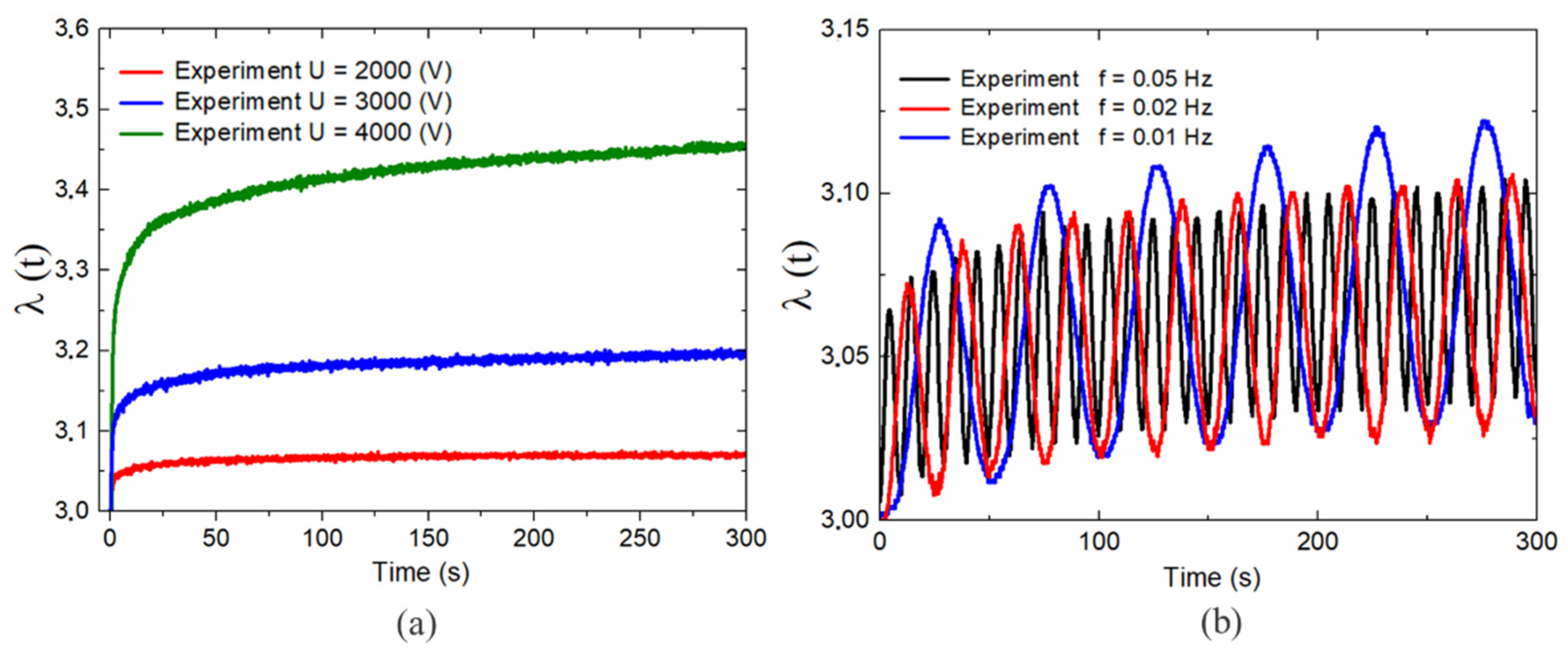
Section 3 presents the experimental results under different steps and alternating voltage signal loads. In
Section 4, we propose the theory of viscoelasticity and establish a constitutive model. The Monte Carlo method and model parameter analysis is applied in
Section 5 to obtain quantitative description parameters to improve the model prediction capabilities.
Section 6 concludes the paper.
The course of the technology research of this paper is shown in
Figure 1.
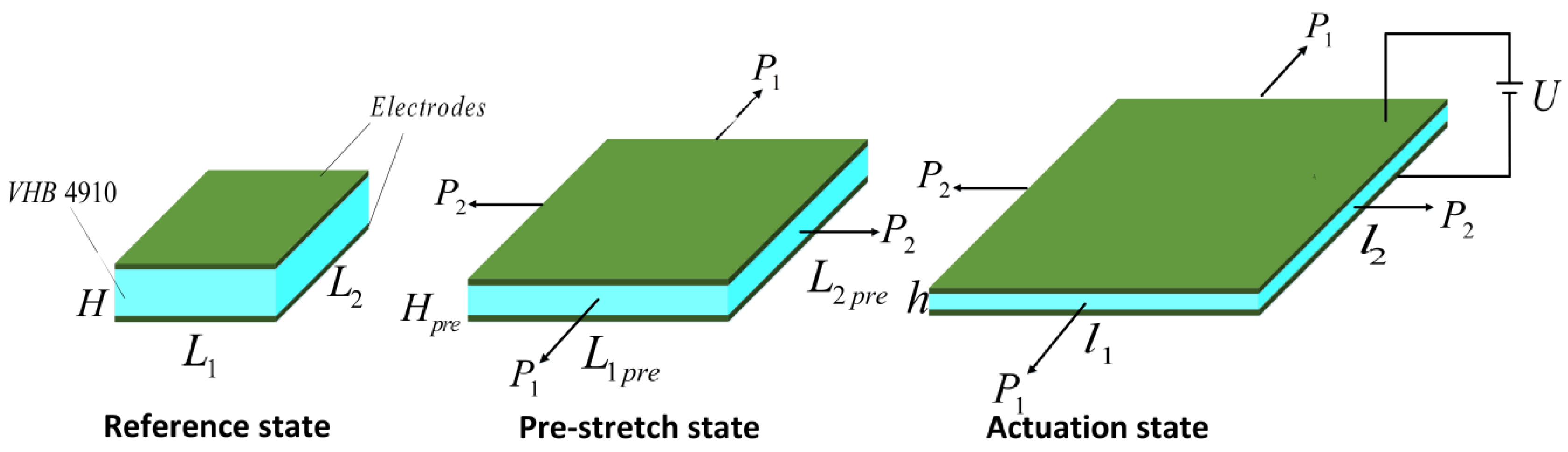
3. Constitutive Modeling
The experimental results discussed above demonstrated that a DE system under voltage excitation exhibited complex, time-dependent, and nonlinear responses. To study the response characteristics of a DE membrane experiencing in-plane deformation, we focused on a widely used configuration in which a membrane of DE was sandwiched between two electrodes. In the reference state with no deformation, the initial length, width, and thickness of the DE membrane were
,
, and
, respectively. Subject to the in-plane mechanical forces
and
, the DE membrane was in a pre-stretched state, where the length and width of the membrane changed to
and
. We express the stretching ratio in the thickness direction as
[
26], meaning
. The two in-plane pre-stresses on the DE are defined as follows:
where
and
are the two in-plane actuation stresses of the DEs.
As we subjected a voltage U through the thickness of the membrane, a dipole phenomena was produced on the two electrodes. The Maxwell force was generated by the attraction of charges between the two electrodes. The membrane expanded in area and shrunk in thickness, and the system reached a new equilibrium state with dimensions
,
, and
. Based on the assumption that the DE membrane acted as a parallel capacitor with compliant electrodes, the relationship between the charges Q and applied voltage U could be expressed as follows [
28,
29,
30]:
where
is the dielectric permittivity of the DE membrane. When the DE membrane was subjected to force and voltage, the variables in Equation (3) are
,
, and
, the variation in the charge is
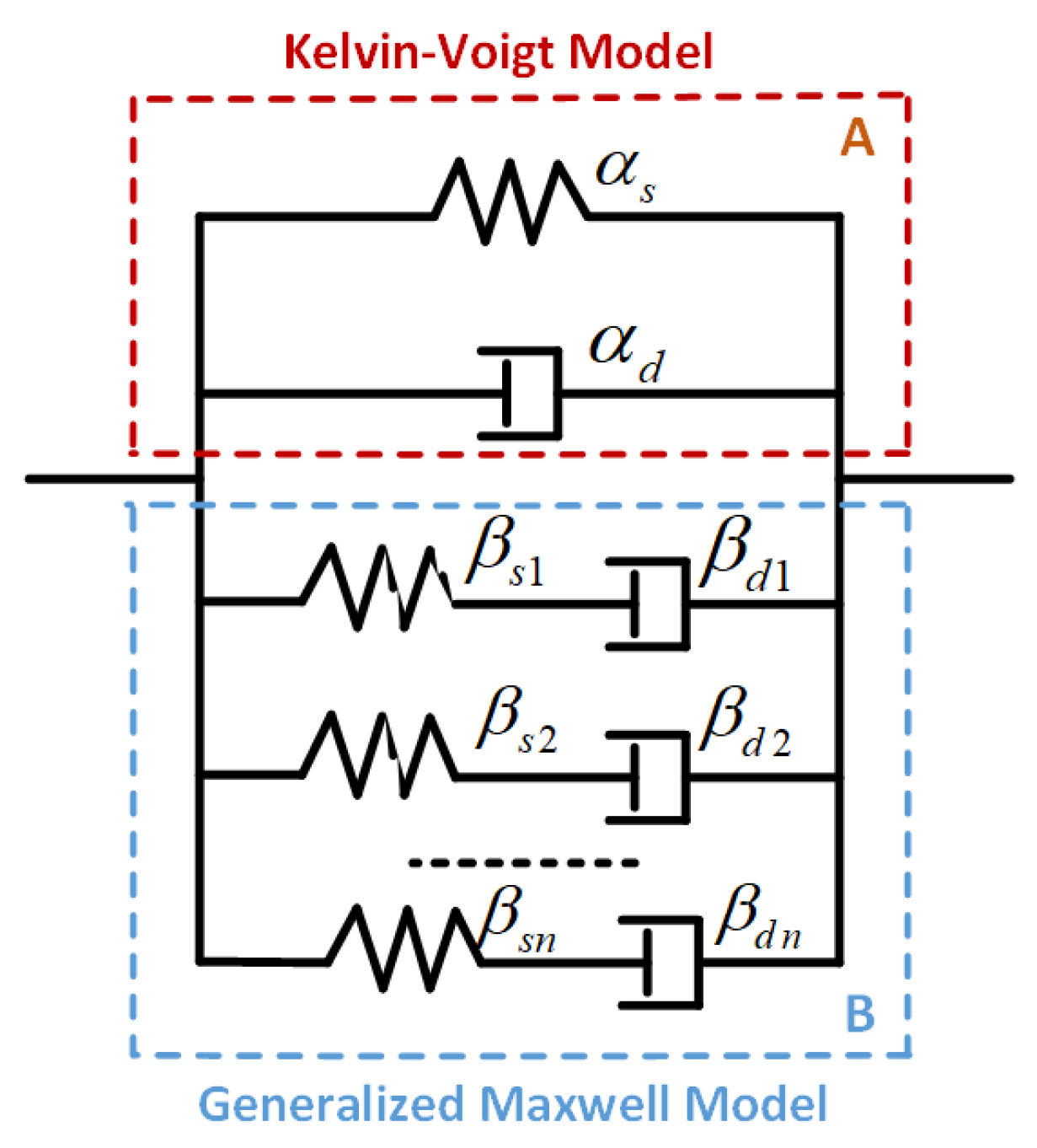
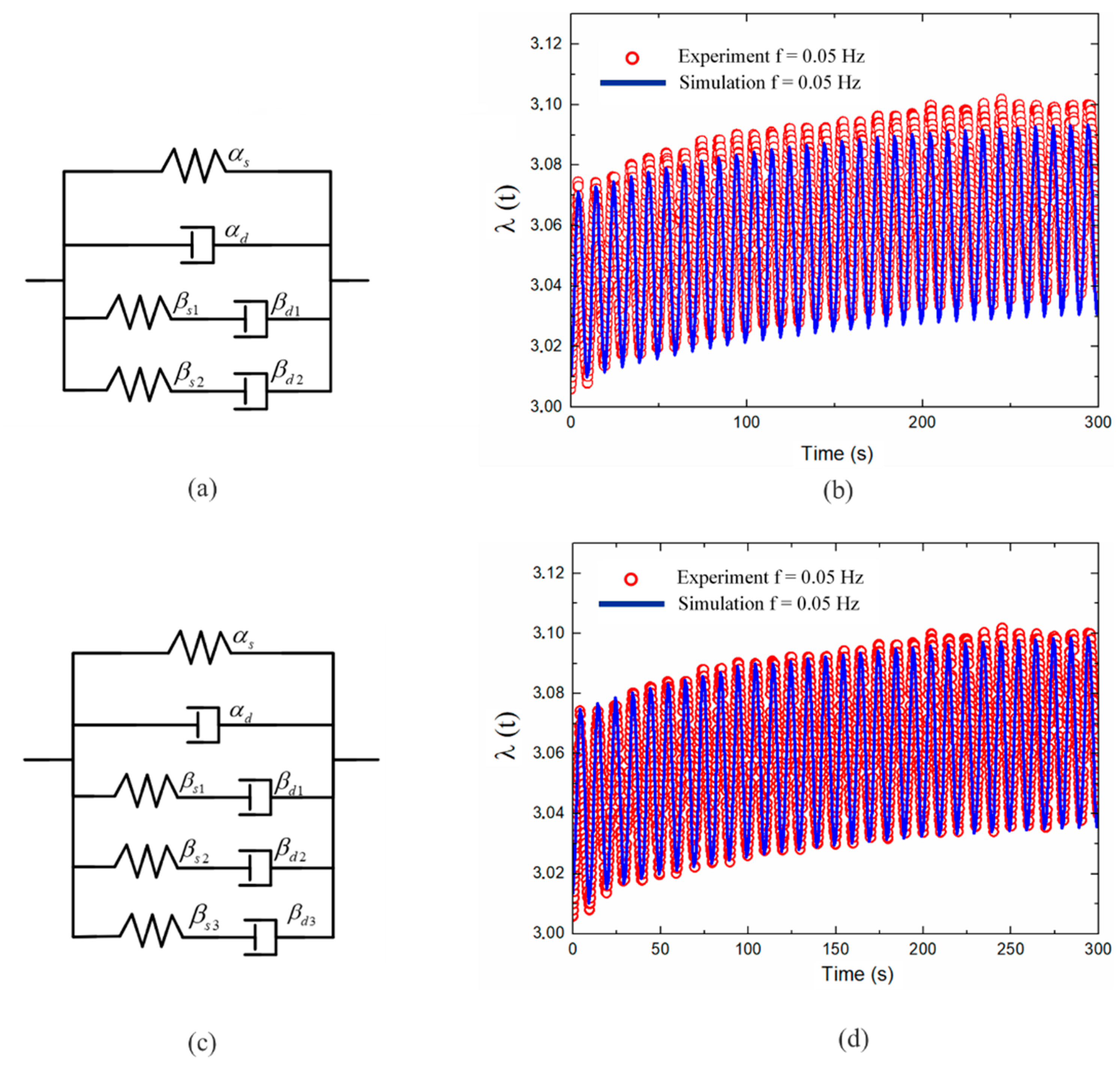
In view of the related works, the Kelvin-Voigt model can better describe the initial creeping behavior [
24], and the generalized Maxwell model is usually adopted to characterize the relaxation stage [
25]. Therefore, in this paper, we parallelly connect both models and name it the Kelvin-Voigt-Generalized Maxwell model (KV-GM) as illustrated in
Figure 5. In this model, we define
and
as the stretching factors in springs
and
,
and
as the stretching factors in dashpots
and
. By referring to the KV-GM model shown in
Figure 5, the total stretching factor of the DE membrane was
. The corresponding net stretching factors of the two parallel parts were equal; thus, by adopting the well-established multiplication rule, we have
[
31].
To describe the free energy density associated with the stretching of the DE, the Gent model [
32] was adopted, which revealed the strain-stiffening performance of the DE. The strain energy of the DE was stored in the springs
and
, and thus the free energy density function could be expressed as follows:
where
and
are the shear moduli, and
and
are the extension limits of the springs in parts A and B, respectively.
When the stretching of the DE membrane varied slightly in the two in-plane directions by
and
, the tensile forces perform work that could be calculated as
. The corresponding increments in the charges of the two electrodes occurred with a small magnitude of
and the work done by the applied voltage was
. During system actuation, the dashpot performed negative work and dissipated energy. The work done by the damping forces in part A is calculated as
and
[
32], where is
the viscous damping coefficient of the dashpot
, and
are
the stretching factors of dashpot
in the two in-plane directions. The work performed by the dashpot
of in B in the two in-plane directions are
and
, where
is the viscous damping coefficient of the dashpot
,
and
are the stretching factors of the dashpot
in the two in-plane directions. During the actuation process, the work performed by the inertial force in the two in-plane directions was calculated as
and
[
33], where
is the density of VHB4910 elastomer. Thermodynamic principles state that the arbitrary variation of a viscoelastic DE system should be equal to the work performed by the applied voltage, tensile force, damping force, and inertia force. The function of the free energy density is defined in (6).
In the following discussion, we consider a special case in which a DE membrane is under equal biaxial stress, that is,
and
. Assuming that the stretching in the dashpot
is consistent with the total stretching of the DE, we could derive
,
, and
. Therefore, (5) and (6) could be rewritten as
The effects of the inertial force on the DE system could be ignored under step-voltage excitation. Based on the standard calculus of variation in (7), we found that:
Based on (4), replacing the charge
with the electrical displacement D yielded
Considering the work performed by the inertia force, for a DE system under the excitation of an alternating load, (8) could be rewritten as
By combining (9) and (10) and eliminating the electrical displacement D, the governing equations could be expressed as follows:
By substituting (11) into (9), we obtained the following dynamic equations for the system:
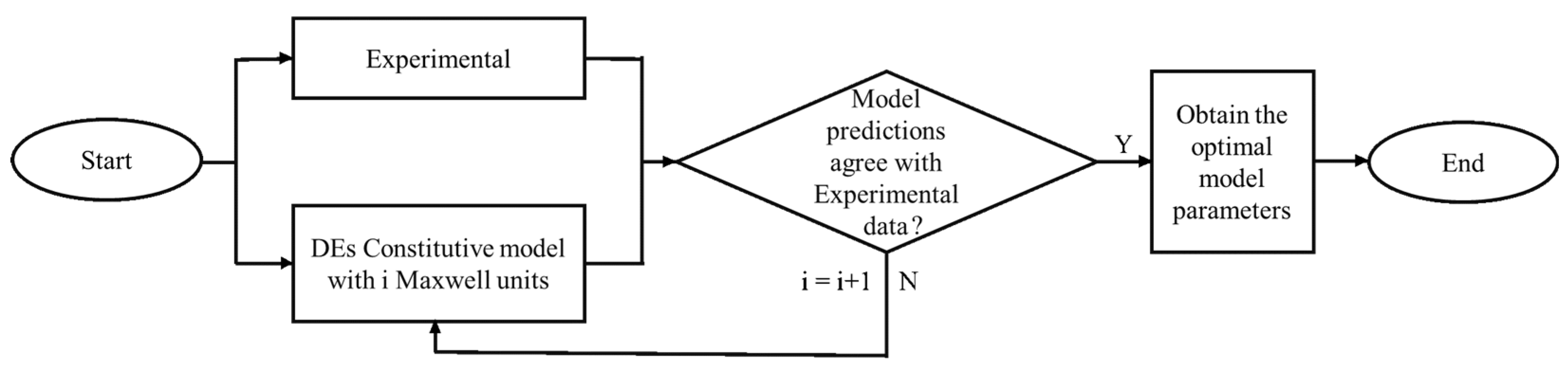
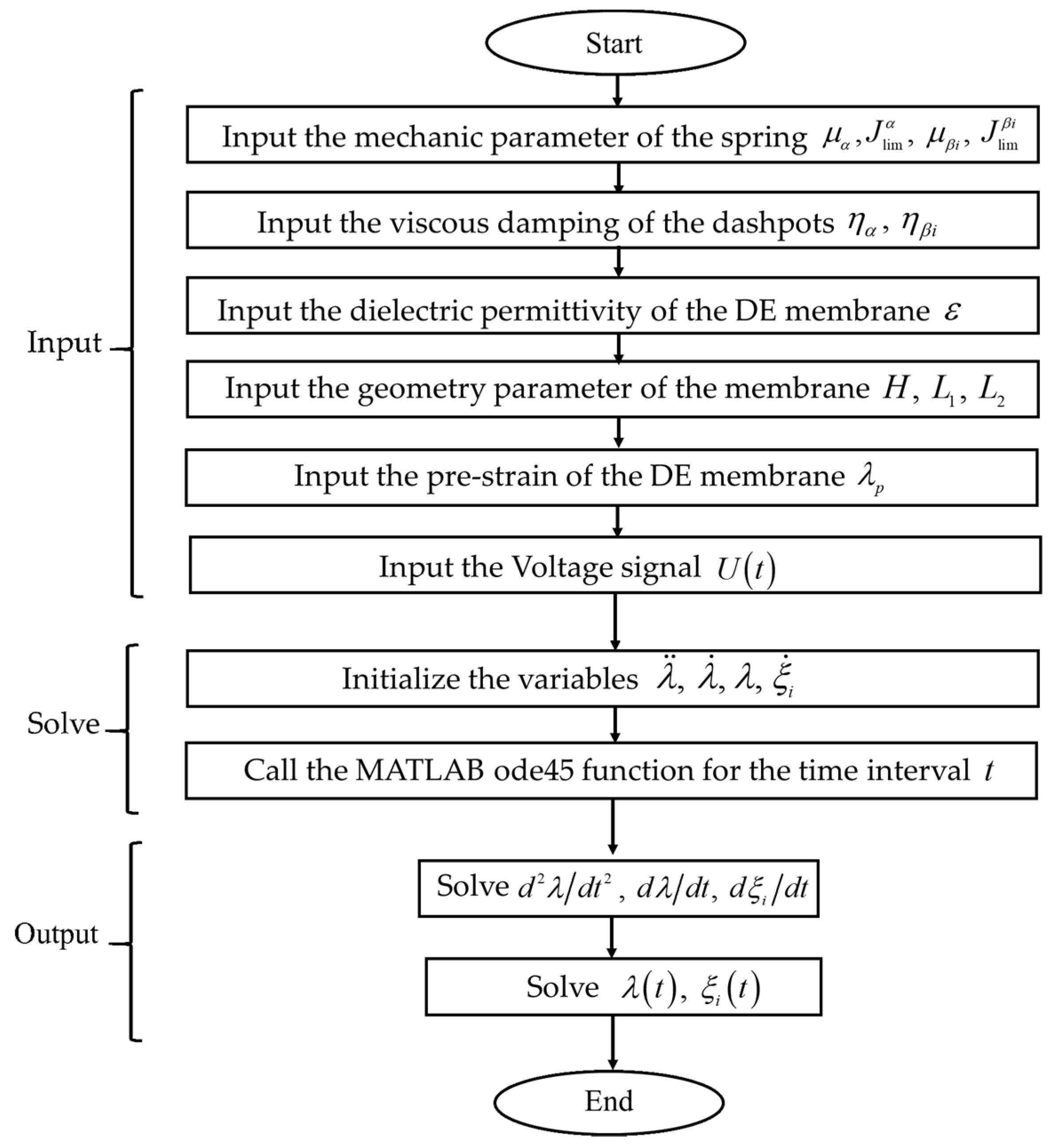
An algorithm for solving the DE equations is shown in
Figure 6. The length of the DE membrane was,
and its thickness was
. The density of the VHB4910 elastomer was
[
33]. The permittivity of DE was
[
26]. In the relaxed state, we applied the initial conditions of
,
,
, and
. The Dormand-Prince method from the Runge-Kutta ODE family of solvers family was adopted in this study to solve the ordinary differential mathematical model. All numerical calculations were conducted using the ode45 function in MATLAB.
5. Discussion
To further quantify the performance of the KV-GM model, the maximum prediction error
and the root-mean-square error
mean are defined as follows:
where
and
present predicted results and experimental data, respectively, and N is the number of measurements.
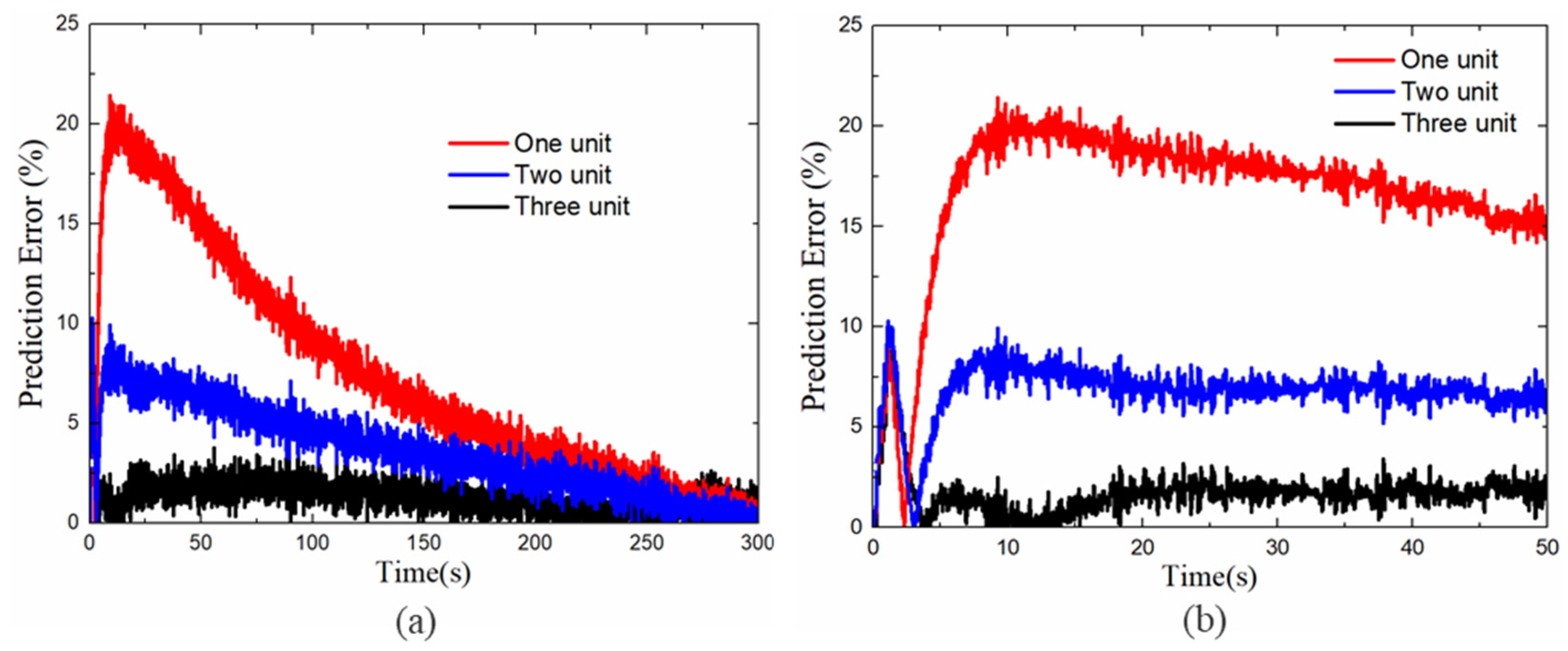
Figure 13a shows the prediction errors of different numbers of Maxwell units with step voltage excitation. The initial 50 s prediction error is shown in
Figure 13b. It can be found that the overshot error occurs in the first 5 s, this phenomenon can be explained as prior to entering the long time relaxation process, the response of displacement mutation and creep stage is relatively complex, which increases the difficulty of the model prediction. On the other hand, the prediction at this stage is mainly determined by the two fixed parameters of Part A of the rheological model as described in
Section 4. As shown in
Figure 13b, when the Maxwell element of the model increases, the overshoot values are 8.841%, 10.26%, 8.931%, respectively. These results show that the change of the Maxwell unit basically does not affect the prediction ability in the initial response state. Therefore, to evaluate the effectiveness of different Maxwell element models, we only consider the error values after the overshoot process. The maximum prediction error of the step voltage excitation and root-mean-square error of the alternating voltage excitation are listed in
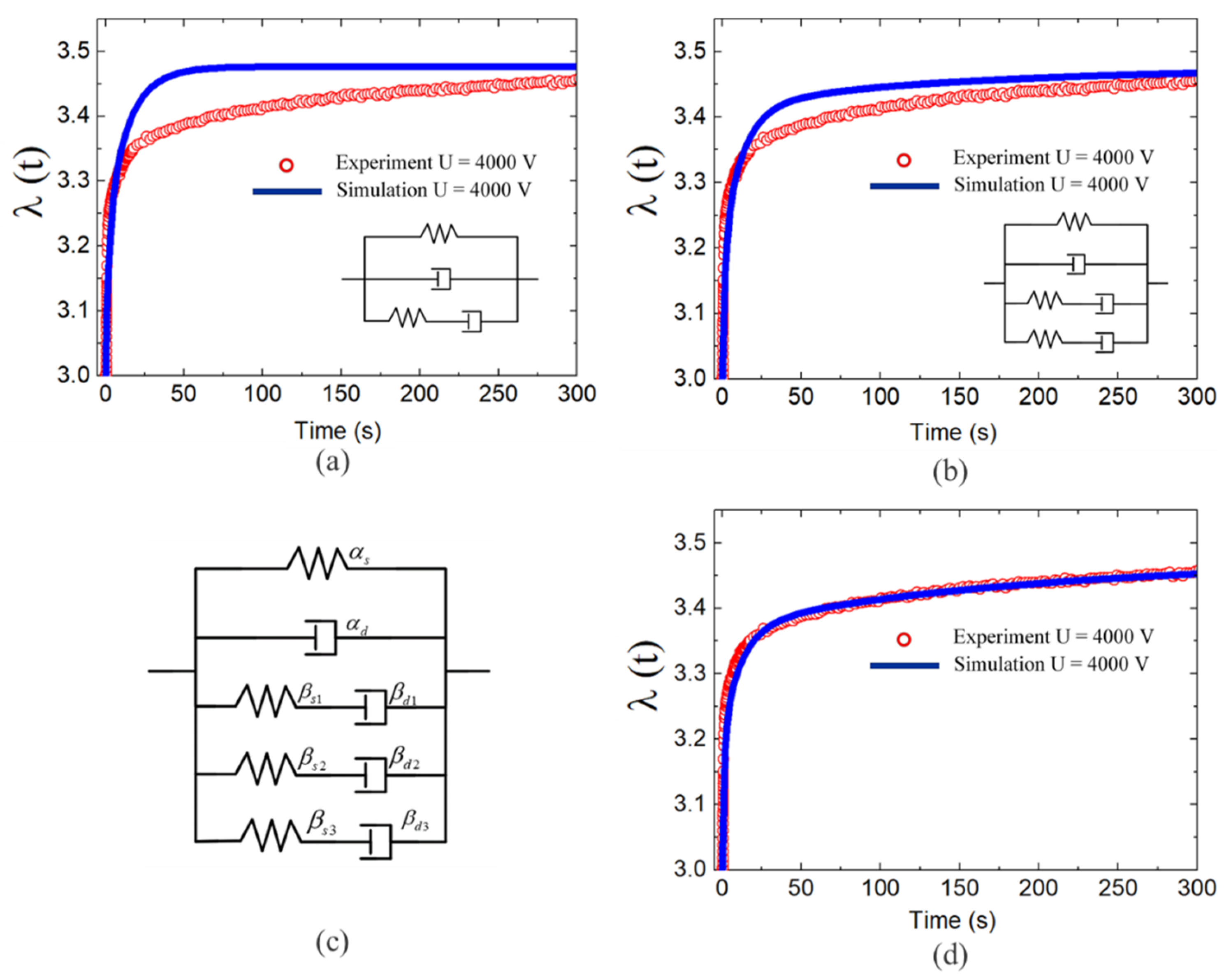
Table 1. We found that the increase of Maxwell unit numbers can reduce the prediction error. It should be noted that a further increase in the numbers of the Maxwell unit (more than 3) causes a further increase in the accuracy of the model, but it will increase the cost of computing. Without loss of generality, in this work, we used three Maxwell units as a research object.
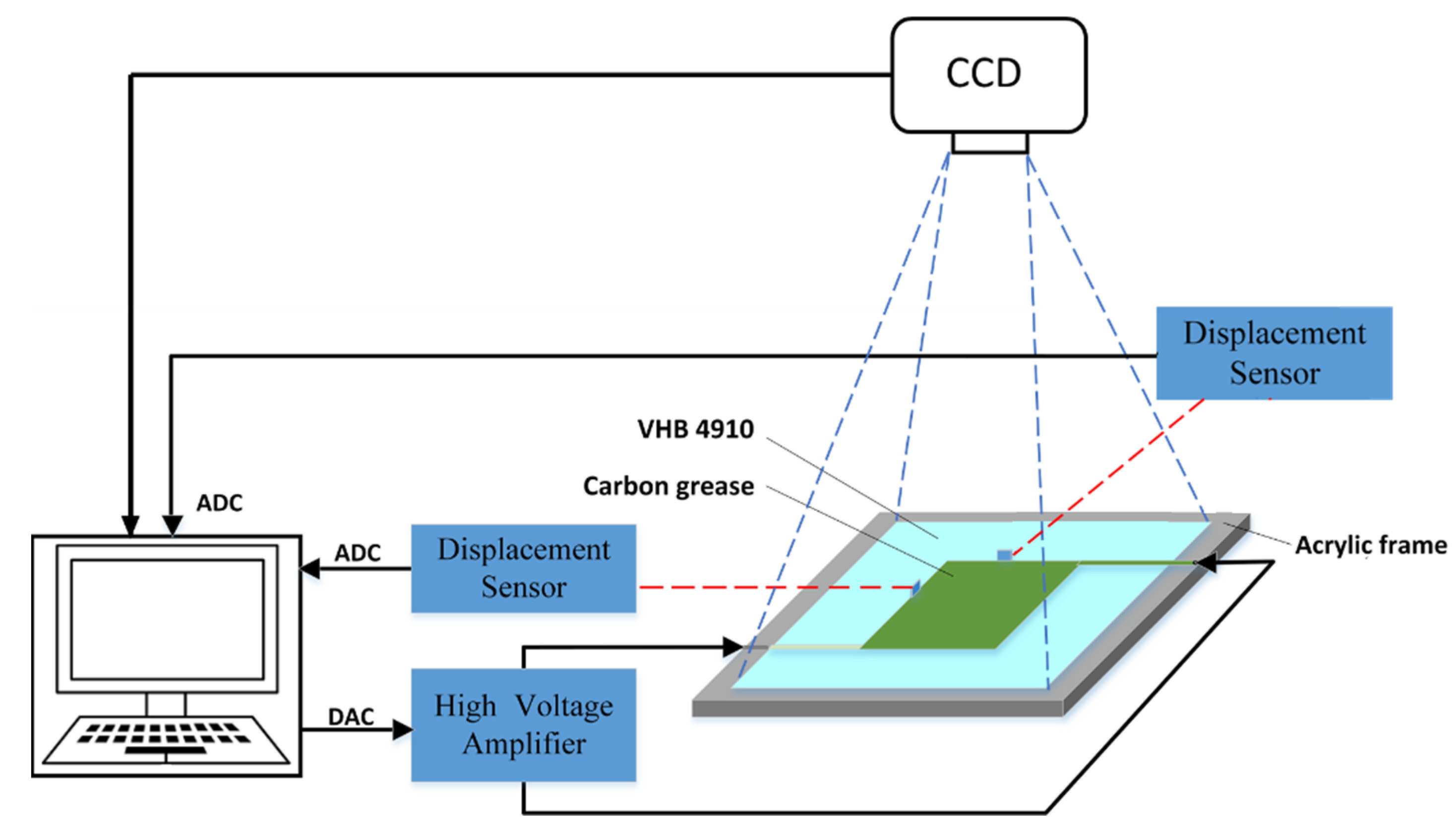
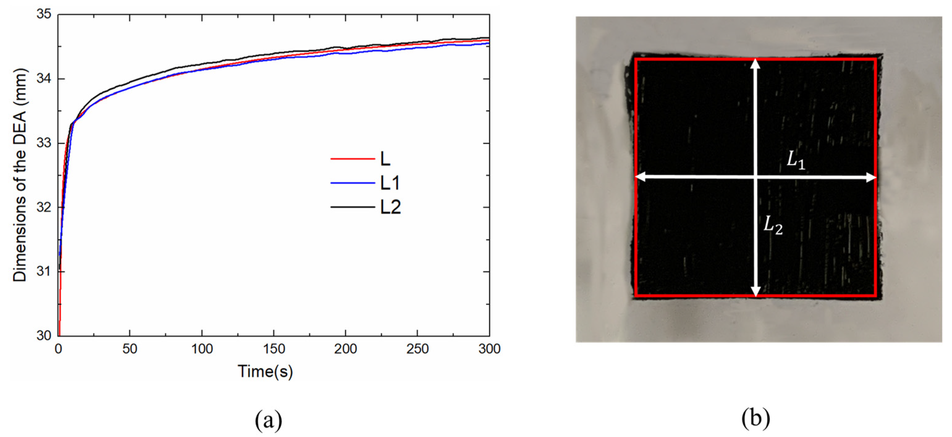
The side lengths of the rectangle DEA are shown in
Figure 14a, where L is the side length of the square calculated by our theoretical model,
and
are the length and width of the rectangle measured by two laser displacement sensors. The discrepancy of
and
indicates that the actuator deforms slightly differently in two in-plane directions. These discrepancies mainly come from the hand-made pre-stretching process, which leads to the tensile force of DES film in the two directions is not exactly the same before actuation.
Figure 14b presents an actuation area by CCD camera, the rectangle in red is the shape of
and
. It is found that the edges of the rectangle are no longer straight, which results in a distortion of the rectangle. For DEs membrane, a frame is used to hold the membrane after pre-stretching, the passive region on the film (flexible electrode uncoated) is limited in area and then results in concentrated stress distribution. During the actuation, it causes uneven tensile force and varies the boundary conditions of the actuator, and results in excessive deformation at the corners.
To further verify the validity of the proposed model and the shape of the DEA in the actuation process, we consider the area deformation of the DEA under a different magnitude of step voltages. The measurement area
and estimation area
and true area
are defined, respectively, as follows:
where
and
is the length of the actuator detected by the displacement sensor in the two in-plane directions,
and
is the length of the actuator calculated by the proposed model in the two in-plane directions.
To verify the validity of the proposed model, we can define the prediction error of the actuator area as follows:
Then, to further verify that the actuator whether can maintain a precise rectangular shape after the pre-stretching and excitation process, we defined
error expressed as:
where
is the area recorded by the CCD external trigger camera.
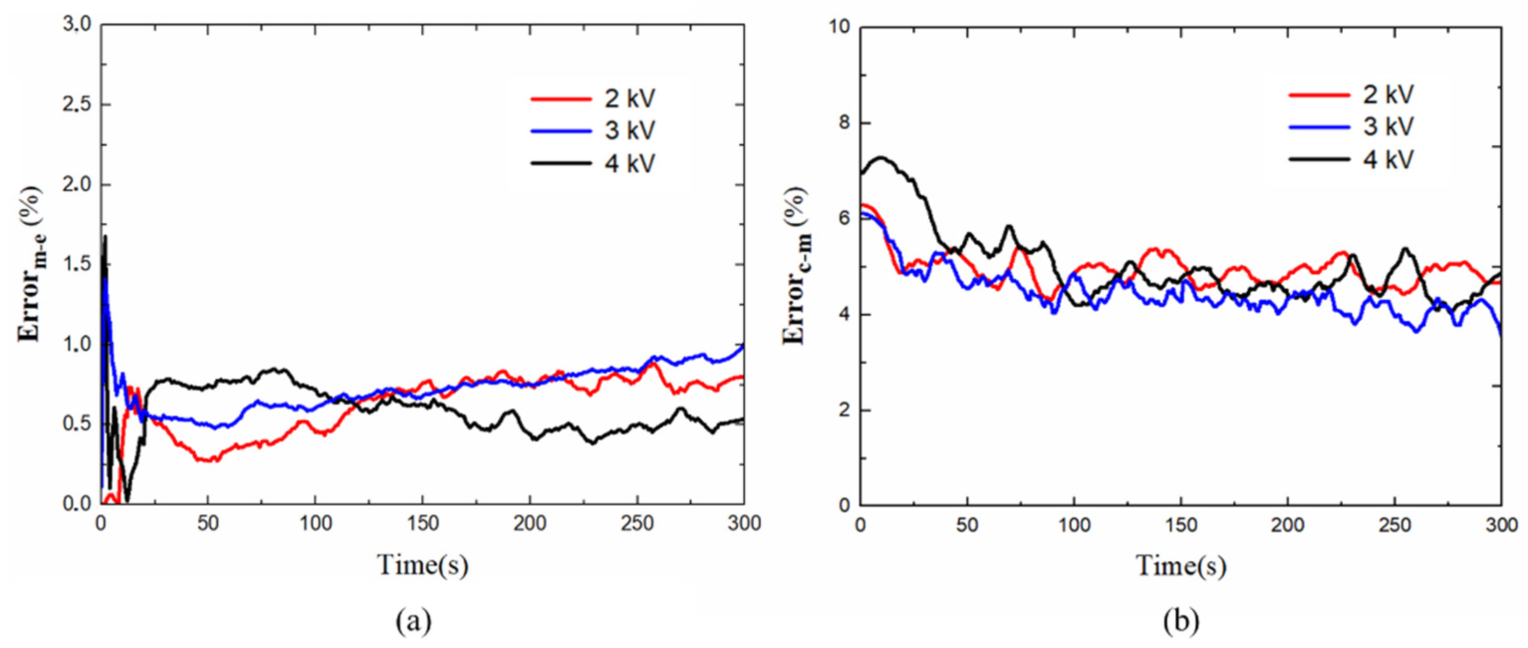
The prediction area errors
of the actuator area under different step voltages are shown in
Figure 15a and the
of the planar DEA as shown in
Figure 15b.
Table 2 shows the maximum value of both errors. In
Figure 15a,b, the maximum error mainly occurs in a few seconds at the initial stage. For the displacement mutation and creeping at the very beginning, the actuator can not be able to relax completely in time, which leads to an increase in the prediction area error. When the voltage increases, the velocity of the deformation grows and the nonlinear viscosity is more significant, the response of the actuator becomes more complex, thus making the prediction of the model more difficult and leads to the error in the initial stage increases with the excitation voltage. After entering the long relaxation phase, the actuator has enough time to relax completely, and the error is smaller. The maximum area errors were 1.674% and 7.485%, respectively, indicating that the proposed model agrees well with experimental measurements and the actuator shape can basically maintain a precise rectangular shape during pre-stretching and high voltage excitation.


