A 3D Printed Composite Scaffold Loaded with Clodronate to Regenerate Osteoporotic Bone: In Vitro Characterization

 ,
,  , ,
, , 


Abstract
1. Introduction
2. Materials and Methods
2.1. Materials
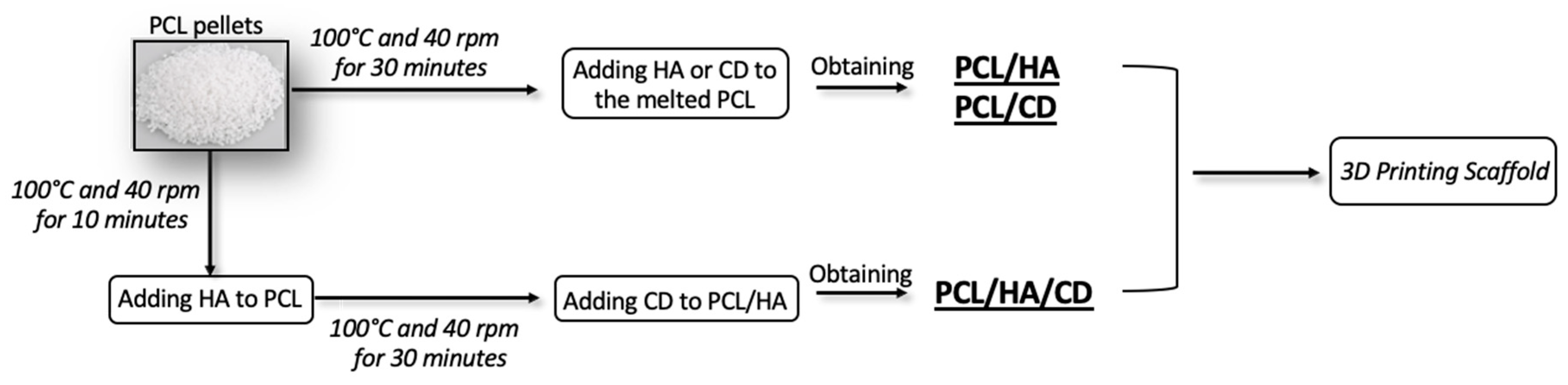
2.2. Physical Blends Preparation
2.3. Scaffold Fabrication
2.4. Scaffold’s Characterization
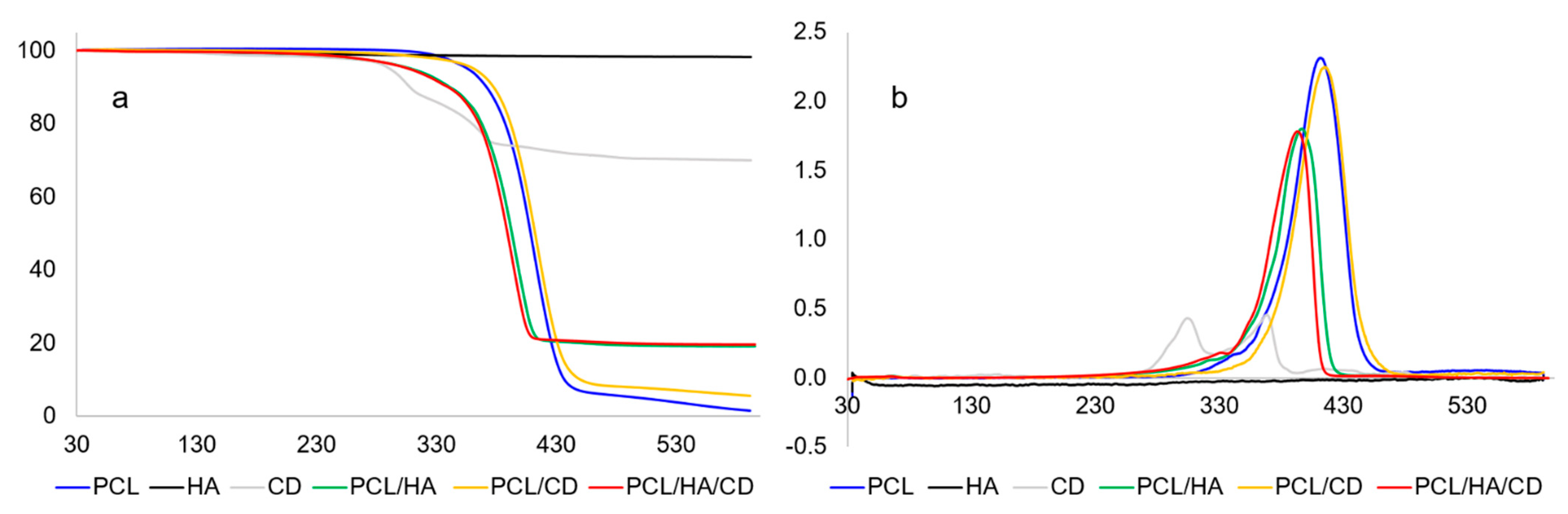
2.4.1. Thermal Analysis
2.4.2. Micro-Computed Tomography (Micro-CT)
2.4.3. Scanning Electron Microscopy (SEM) with Energy Dispersive X-ray Spectroscopy (EDX)
2.4.4. X-ray Photoelectron Spectroscopy (XPS)
2.4.5. Mechanical Analysis
2.4.6. Biological Analysis
Cell Culture
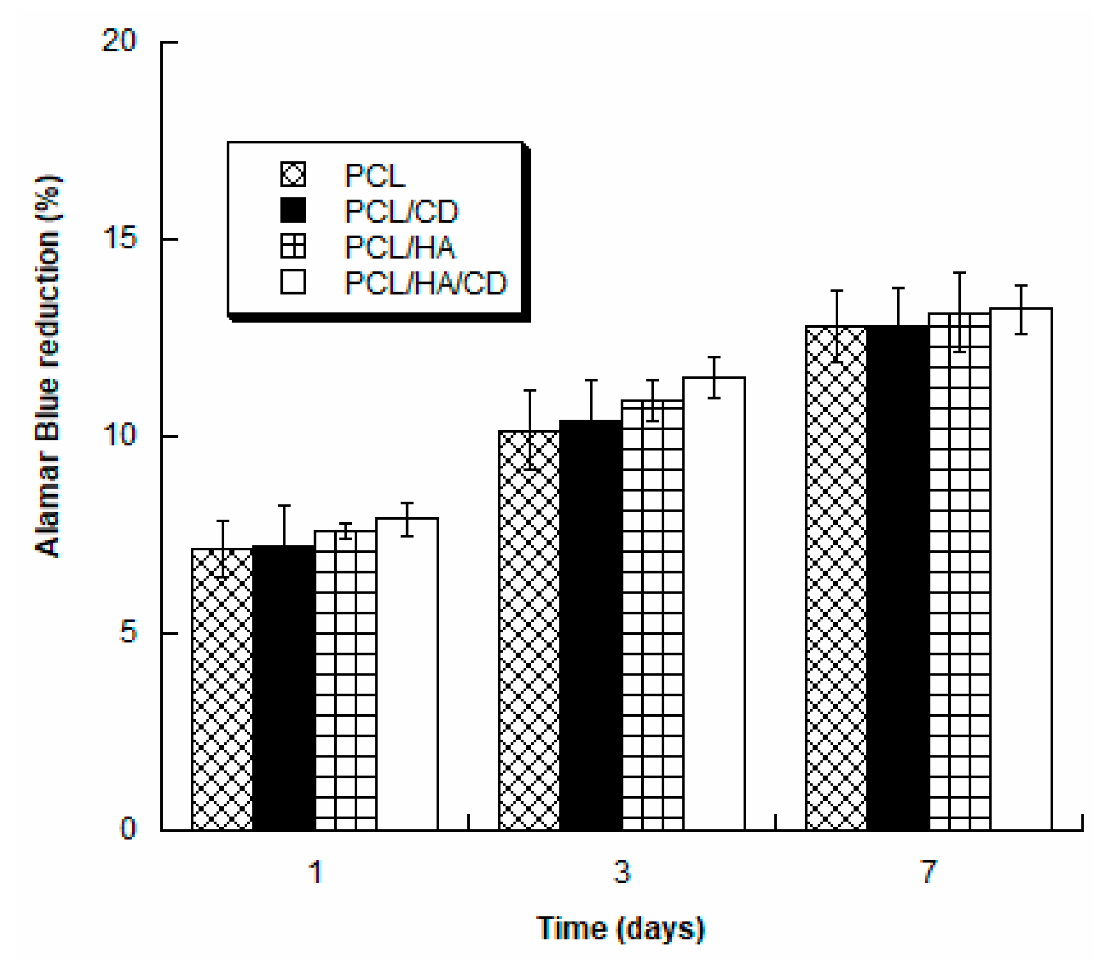
Alamar Blue Assay
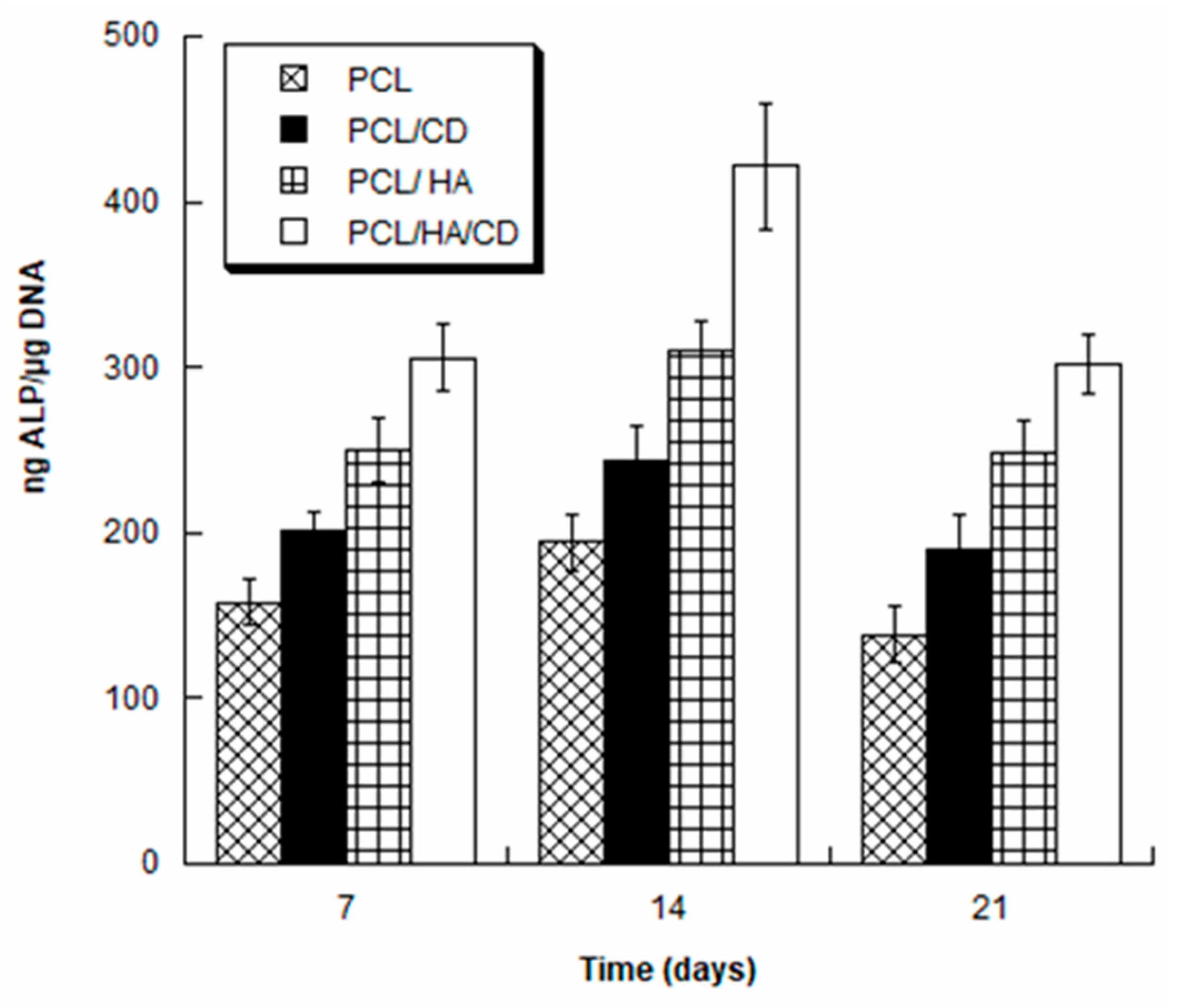
Alkaline Phosphatase Activity
2.4.7. Statistical Analysis
3. Results and Discussion
3.1. Thermal Characterization
3.2. Morphological Characterization
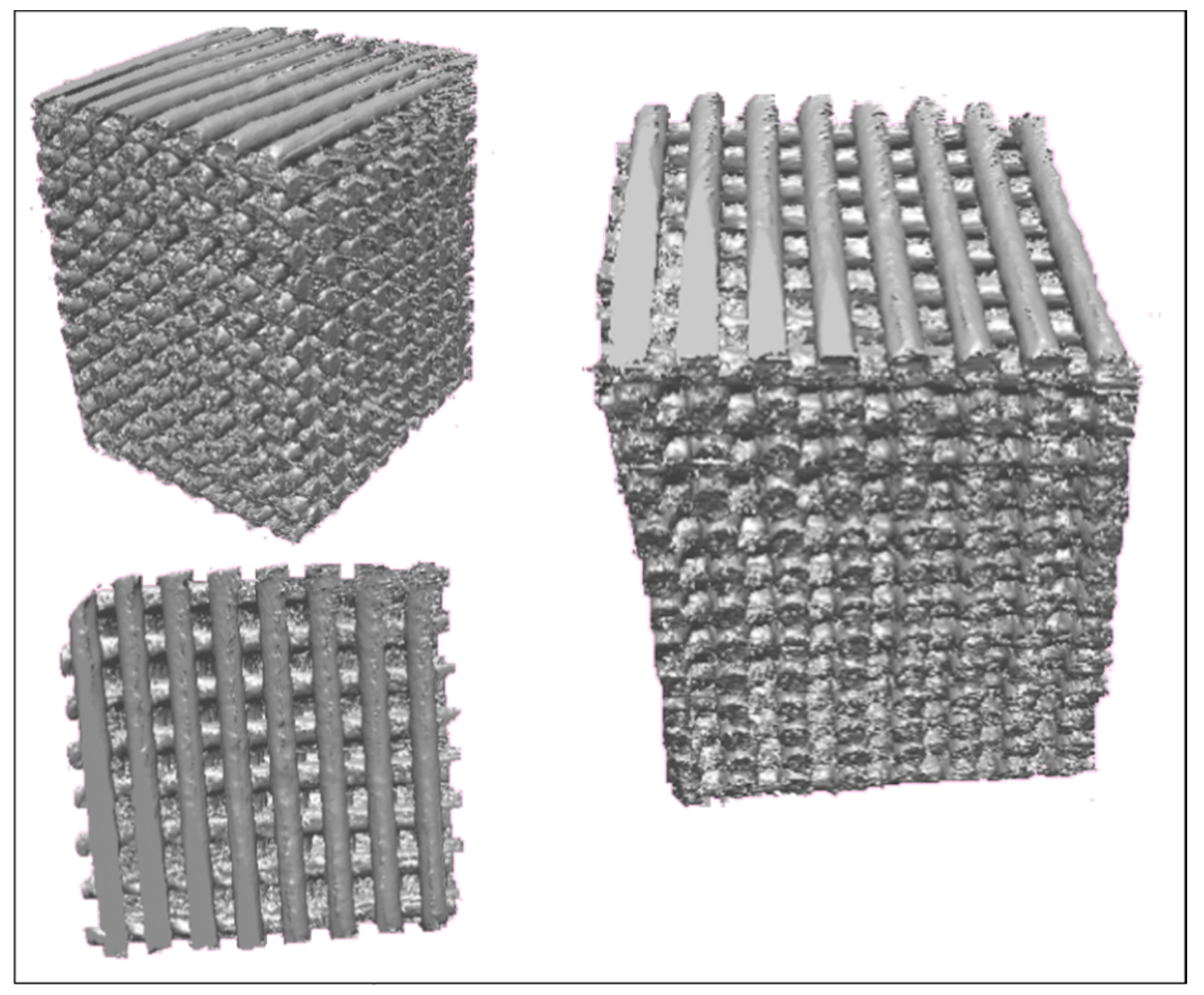
3.2.1. Micro-Computed Tomography (Micro-CT)
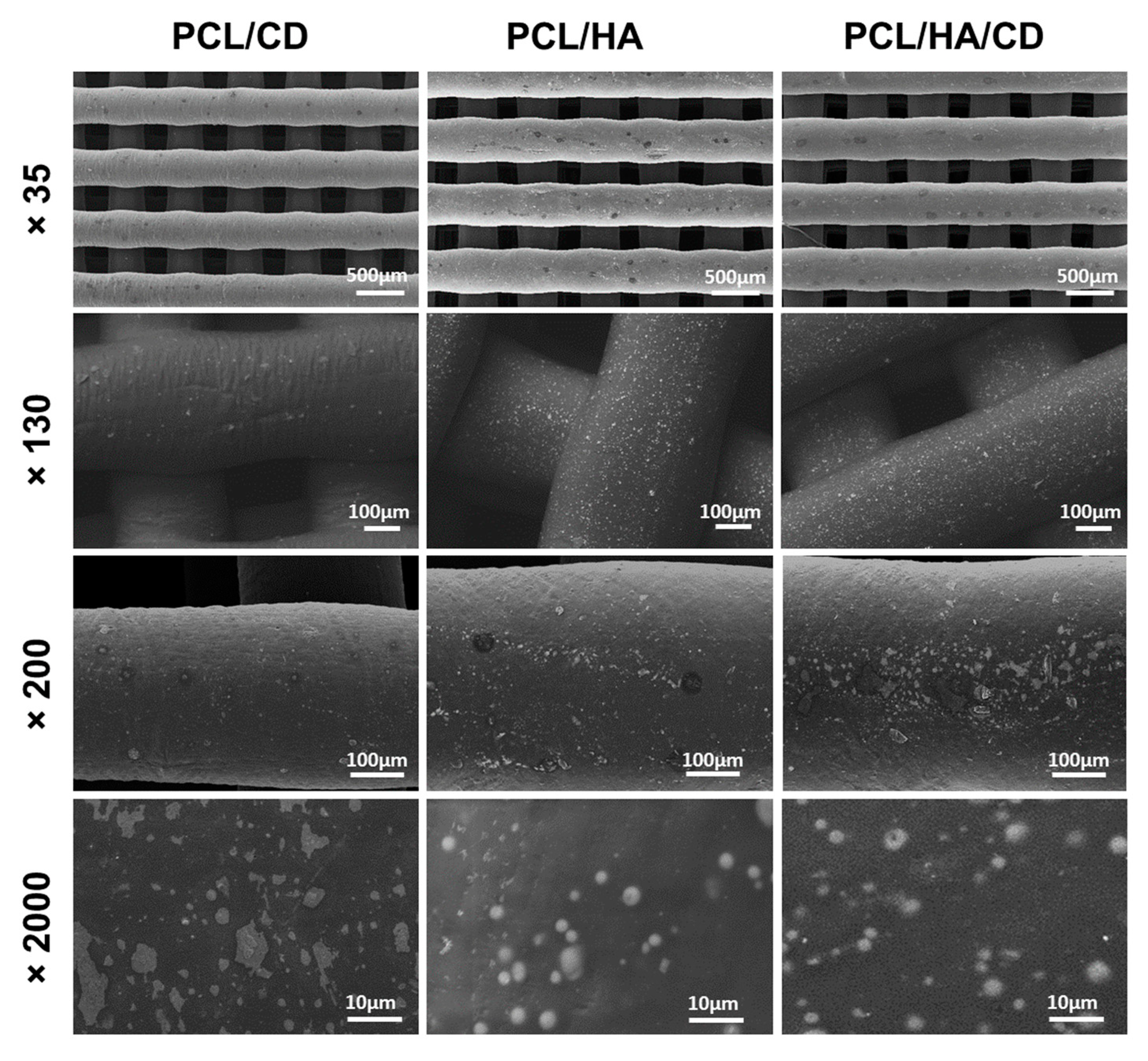
3.2.2. Scanning Electron Microscopy (SEM)
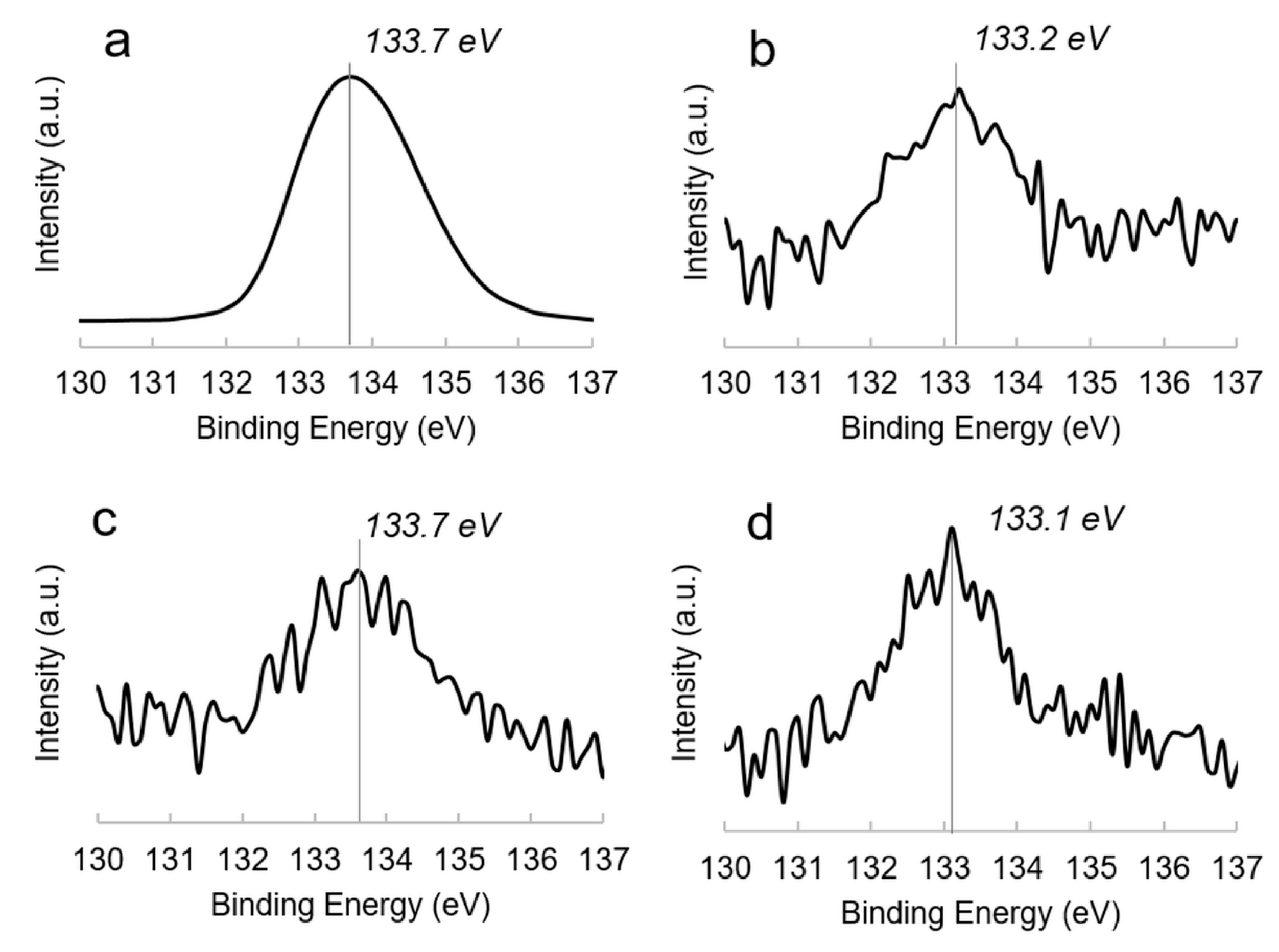
3.3. XPS Analysis
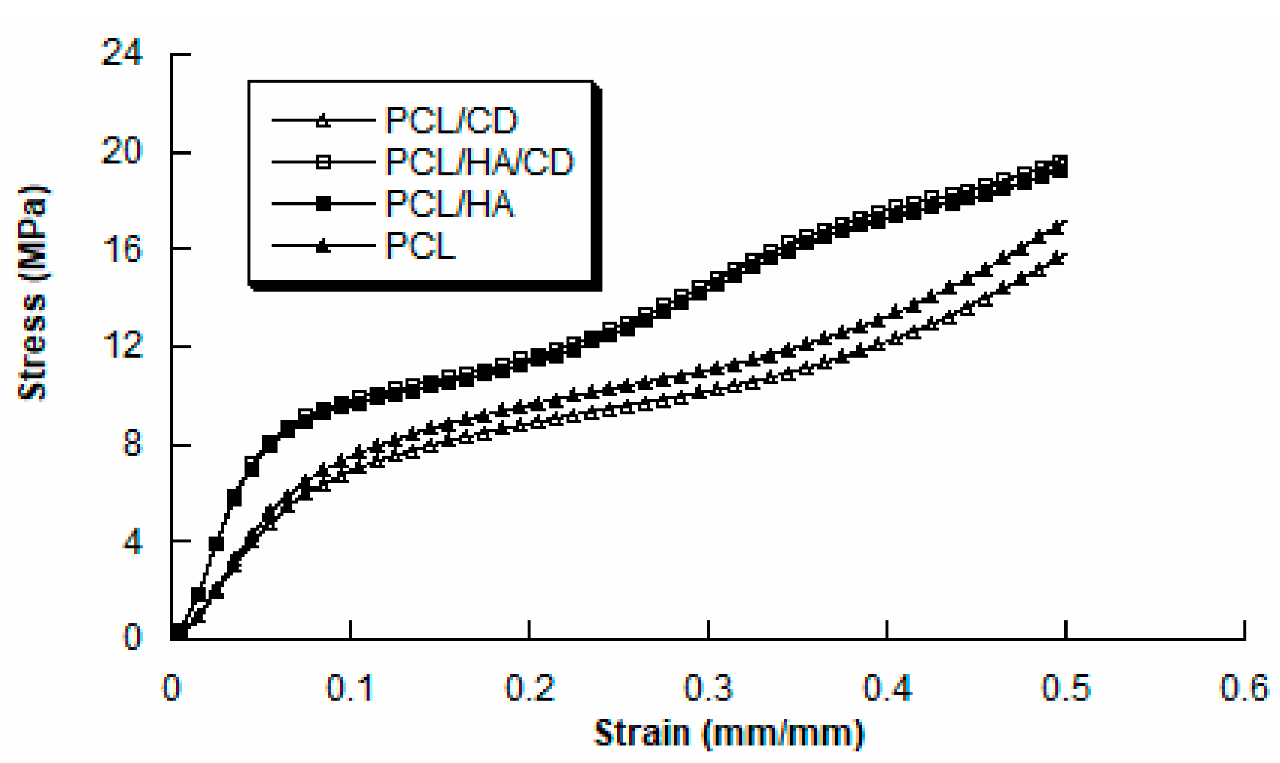
3.4. Mechanical Analysis
3.5. Biological Analysis
4. Conclusions
Supplementary Materials
Author Contributions
Funding
Institutional Review Board Statement
Informed Consent Statement
Data Availability Statement
Acknowledgments
Conflicts of Interest
References
- Pecci, R.; Baiguera, S.; Ioppolo, P.; Bedini, R.; del Gaudio, C. 3d printed scaffolds with random microarchitecture for bone tissue engineering applications: Manufacturing and characterization. J. Mech. Behav. Biomed. Mater. 2020, 103, 103583. [Google Scholar] [CrossRef] [PubMed]
- Qu, H. Additive manufacturing for bone tissue engineering scaffolds. Mater. Today Commun. 2020, 24, 101024. [Google Scholar] [CrossRef]
- Mohammed, A.; Elshaer, A.; Sareh, P.; Elsayed, M.; Hassanin, H. Additive manufacturing technologies for drug delivery applications. Int. J. Pharm. 2020, 580, 119245. [Google Scholar] [CrossRef] [PubMed]
- Hutmacher, D.W. Scaffolds in tissue engineering bone and cartilage. Biomaterials 2000, 21, 2529–2543. [Google Scholar] [CrossRef]
- Groll, J.; Boland, T.; Blunk, T.; Burdick, J.A.; Cho, D.-W.; Dalton, P.D.; Derby, B.; Forgacs, G.; Li, Q.; Mironov, V.A. Biofabrication: Reappraising the definition of an evolving field. Biofabrication 2016, 8, 013001. [Google Scholar] [CrossRef] [PubMed]
- Pati, F.; Jang, J.; Lee, J.W.; Cho, D.-W. Chapter 7—Extrusion bioprinting. In Essentials of 3d Biofabrication and Translation; Atala, A., Yoo, J.J., Eds.; Academic Press: Boston, MA, USA, 2015; pp. 123–152. [Google Scholar]
- Tarafder, S.; Balla, V.K.; Davies, N.M.; Bandyopadhyay, A.; Bose, S. Microwave-sintered 3d printed tricalcium phosphate scaffolds for bone tissue engineering. J. Tissue Eng. Regen. Med. 2013, 7, 631–641. [Google Scholar] [CrossRef]
- Skoog, S.A.; Goering, P.L.; Narayan, R.J. Stereolithography in tissue engineering. J. Mater. Sci. Mater. Med. 2014, 25, 845–856. [Google Scholar] [CrossRef]
- Dhandapani, R.; Krishnan, P.D.; Zennifer, A.; Kannan, V.; Manigandan, A.; Arul, M.R.; Jaiswal, D.; Subramanian, A.; Kumbar, S.G.; Sethuraman, S. Additive manufacturing of biodegradable porous orthopaedic screw. Bioact. Mater. 2020, 5, 458–467. [Google Scholar] [CrossRef]
- Bartolo, P.; Domingos, M.; Gloria, A.; Ciurana, J. BioCell printing: Integrated automated assembly system for tissue engineering constructs. CIRP Ann. 2011, 60, 271–274. [Google Scholar] [CrossRef]
- Melchels, F.P.; Domingos, M.A.; Klein, T.J.; Malda, J.; Bartolo, P.J.; Hutmacher, D.W. Additive manufacturing of tissues and organs. Prog. Polym. Sci. 2012, 37, 1079–1104. [Google Scholar] [CrossRef]
- Williams, J.M.; Adewunmi, A.; Schek, R.M.; Flanagan, C.L.; Krebsbach, P.H.; Feinberg, S.E.; Hollister, S.J.; Das, S. Bone tissue engineering using polycaprolactone scaffolds fabricated via selective laser sintering. Biomaterials 2005, 26, 4817–4827. [Google Scholar] [CrossRef] [PubMed]
- Koh, Y.-H.; Bae, C.-J.; Sun, J.-J.; Jun, I.-K.; Kim, H.-E. Macrochanneled poly (ɛ-caprolactone)/hydroxyapatite scaffold by combination of bi-axial machining and lamination. J. Mater. Sci. Mater. Med. 2006, 17, 773–778. [Google Scholar] [CrossRef]
- Rai, B.; Oest, M.E.; Dupont, K.M.; Ho, K.H.; Teoh, S.H.; Guldberg, R.E. Combination of platelet-rich plasma with polycaprolactone-tricalcium phosphate scaffolds for segmental bone defect repair. J. Biomed. Mater. Res. Part A 2007, 81, 888–899. [Google Scholar] [CrossRef] [PubMed]
- Domingos, M.; Chiellini, F.; Cometa, S.; de Giglio, E.; Grillo-Fernandes, E.; Bártolo, P.; Chiellini, E. Evaluation of in vitro degradation of pcl scaffolds fabricated via bioextrusion. Part 1: Influence of the degradation environment. Virtual Phys. Prototyp. 2010, 5, 65–73. [Google Scholar] [CrossRef]
- Bose, S.; Sarkar, N.; Vahabzadeh, S. Sustained release of vitamin c from pcl coated tcp induces proliferation and differentiation of osteoblast cells and suppresses osteosarcoma cell growth. Mater. Sci. Eng. C 2019, 105, 110096. [Google Scholar] [CrossRef]
- Savarino, L.; Baldini, N.; Greco, M.; Capitani, O.; Pinna, S.; Valentini, S.; Lombardo, B.; Esposito, M.; Pastore, L.; Ambrosio, L. The performance of poly-ε-caprolactone scaffolds in a rabbit femur model with and without autologous stromal cells and bmp4. Biomaterials 2007, 28, 3101–3109. [Google Scholar] [CrossRef]
- Ferreira, J.; Gloria, A.; Cometa, S.; Coelho, J.F.; Domingos, M. Effect of in vitro enzymatic degradation on 3d printed poly (ε-caprolactone) scaffolds: Morphological, chemical and mechanical properties. J. Appl. Biomater. Funct. Mater. 2017, 15, 185–195. [Google Scholar] [CrossRef]
- Saleh, L.S.; Bryant, S.J. The host response in tissue engineering: Crosstalk between immune cells and cell-laden scaffolds. Curr. Opin. Biomed. Eng. 2018, 6, 58–65. [Google Scholar] [CrossRef]
- Dwivedi, R.; Kumar, S.; Pandey, R.; Mahajan, A.; Nandana, D.; Katti, D.S.; Mehrotra, D. Polycaprolactone as biomaterial for bone scaffolds: Review of literature. J. Oral Biol. Craniofacial Res. 2020, 10, 381–388. [Google Scholar] [CrossRef]
- Senköylü, A.; Ural, E.; Kesenci, K.; Sìmşek, A.; Ruacan, S.; Fambri, L.; Migliaresi, C.; Piskin, E. Poly (d, l-lactide/epsilon-caprolactone)/hydroxyapatite composites as bone filler: An in vivo study in rats. Int. J. Artif. organs 2002, 25, 1174–1179. [Google Scholar] [CrossRef]
- Roohani-Esfahani, S.-I.; Nouri-Khorasani, S.; Lu, Z.; Appleyard, R.; Zreiqat, H. The influence hydroxyapatite nanoparticle shape and size on the properties of biphasic calcium phosphate scaffolds coated with hydroxyapatite–pcl composites. Biomaterials 2010, 31, 5498–5509. [Google Scholar] [CrossRef] [PubMed]
- Schiller, C.; Epple, M. Carbonated calcium phosphates are suitable ph-stabilising fillers for biodegradable polyesters. Biomaterials 2003, 24, 2037–2043. [Google Scholar] [CrossRef]
- Cremers, S.; Drake, M.T.; Ebetino, F.H.; Rogers, M.J.; Bilezikian, J.P.; Russell, R.G.G. Clinical and translational pharmacology of bisphosphonates. In Principles of Bone Biology; Elsevier: Amsterdam, The Netherlands, 2020; pp. 1671–1687. [Google Scholar]
- Cui, Y.; Zhu, T.; Li, D.; Li, Z.; Leng, Y.; Ji, X.; Liu, H.; Wu, D.; Ding, J. Bisphosphonate-functionalized scaffolds for enhanced bone regeneration. Adv. Healthc. Mater. 2019, 8, 1901073. [Google Scholar] [CrossRef] [PubMed]
- Rather, B.A.; Bhat, S.A. Bisphosphonates in clinical practice. JMS SKIMS 2019, 22, 93–95. [Google Scholar] [CrossRef]
- Soares, A.P.; Santo, R.F.d.E.; Line, S.R.P.; Pinto, M.d.G.F.; Santos, P.d.; Toralles, M.B.P.; Santo, A.R.d.E. Bisphosphonates: Pharmacokinetics, bioavailability, mechanisms of action, clinical applications in children, and effects on tooth development. Environ. Toxicol. Pharmacol. 2016, 42, 212–217. [Google Scholar] [CrossRef] [PubMed]
- Lin, T.-J. Predicting binding affinities of nitrogen-containing bisphosphonates on hydroxyapatite surface by molecular dynamics. Chem. Phys. Lett. 2019, 716, 83–92. [Google Scholar] [CrossRef]
- Meyer, J.L.; Nancollas, G.H. The influence of multidentate organic phosphonates on the crystal growth of hydroxyapatite. Calcif. Tissue Res. 1973, 13, 295–303. [Google Scholar] [CrossRef]
- Forte, L.; Sarda, S.; Torricelli, P.; Combes, C.; Brouillet, F.; Marsan, O.; Salamanna, F.; Fini, M.; Boanini, E.; Bigi, A. Multifunctionalization modulates hydroxyapatite surface interaction with bisphosphonate: Antiosteoporotic and antioxidative stress materials. ACS Biomater. Sci. Eng. 2019, 5, 3429–3439. [Google Scholar] [CrossRef]
- Farrell, K.B.; Karpeisky, A.; Thamm, D.H.; Zinnen, S. Bisphosphonate conjugation for bone specific drug targeting. Bone Rep. 2018, 9, 47–60. [Google Scholar] [CrossRef]
- Rogers, M.J. New insights into the molecular mechanisms of action of bisphosphonates. Curr. Pharm. Design 2003, 9, 2643–2658. [Google Scholar] [CrossRef]
- Scala, R.; Angelelli, M.; Maqoud, F.; Scilimati, A.; Tricarico, D. Bisphosphonates regulate osteoblasts/osteoclasts proliferation inducing bone mineralization. Biophys. J. 2018, 114, 334a–335a. [Google Scholar] [CrossRef]
- Van Beek, E.; Löwik, C.; Papapoulos, S. Bisphosphonates suppress bone resorption by a direct effect on early osteoclast precursors without affecting the osteoclastogenic capacity of osteogenic cells: The role of protein geranylgeranylation in the action of nitrogencontaining bisphosphonates on osteoclast precursors. Bone 2002, 30, 64–70. [Google Scholar] [PubMed]
- Gossiel, F.; Hoyle, C.; McCloskey, E.; Naylor, K.; Walsh, J.; Peel, N.; Eastell, R. The effect of bisphosphonate treatment on osteoclast precursor cells in postmenopausal osteoporosis: The trio study. Bone 2016, 92, 94–99. [Google Scholar] [CrossRef] [PubMed]
- Plotkin, L.I.; Buvinic, S.; Balanta-Melo, J. In vitro and in vivo studies using non-traditional bisphosphonates. Bone 2020, 134, 115301. [Google Scholar] [CrossRef]
- Katsumi, H.; Tanaka, Y.; Hitomi, K.; Liu, S.; Quan, Y.-s.; Kamiyama, F.; Sakane, T.; Yamamoto, A. Efficient transdermal delivery of alendronate, a nitrogen-containing bisphosphonate, using tip-loaded self-dissolving microneedle arrays for the treatment of osteoporosis. Pharmaceutics 2017, 9, 29. [Google Scholar] [CrossRef]
- Alghamdi, H.S.; Bosco, R.; Both, S.K.; Iafisco, M.; Leeuwenburgh, S.C.; Jansen, J.A.; van den Beucken, J.J. Synergistic effects of bisphosphonate and calcium phosphate nanoparticles on peri-implant bone responses in osteoporotic rats. Biomaterials 2014, 35, 5482–5490. [Google Scholar] [CrossRef]
- Bigi, A.; Boanini, E. Calcium phosphates as delivery systems for bisphosphonates. J. Funct. Biomater. 2018, 9, 6. [Google Scholar] [CrossRef]
- Kolmas, J.; Sobczak, M.; Olędzka, E.; Nałęcz-Jawecki, G.; Dębek, C. Synthesis, characterization and in vitro evaluation of new composite bisphosphonate delivery systems. Int. J. Mol. Sci. 2014, 15, 16831–16847. [Google Scholar] [CrossRef]
- Chen, J.; Luo, Y.; Hong, L.; Ling, Y.; Pang, J.; Fang, Y.; Wei, K.; Gao, X. Synthesis, characterization and osteoconductivity properties of bone fillers based on alendronate-loaded poly (ε-caprolactone)/hydroxyapatite microspheres. J. Mater. Sci. Mater. Med. 2011, 22, 547–555. [Google Scholar] [CrossRef]
- Puppi, D.; Piras, A.M.; Chiellini, F.; Chiellini, E.; Martins, A.; Leonor, I.B.; Neves, N.; Reis, R. Optimized electro-and wet-spinning techniques for the production of polymeric fibrous scaffolds loaded with bisphosphonate and hydroxyapatite. J. Tissue Eng. Regen. Med. 2011, 5, 253–263. [Google Scholar] [CrossRef]
- Domingos, M.; Intranuovo, F.; Russo, T.; Santis, R.D.; Gloria, A.; Ambrosio, L.; Ciurana, J.; Bartolo, P. The first systematic analysis of 3d rapid prototyped poly(ε- caprolactone) scaffolds manufactured through BioCell printing: The effect of pore size and geometry on compressive mechanical behaviour and in vitro hmsc viability. Biofabrication 2013, 5. [Google Scholar] [CrossRef] [PubMed]
- Wang, H.; Domingos, M.; Scenini, F. Advanced mechanical and thermal characterization of 3d bioextruded poly(e-caprolactone)-based composites. Rapid Prototyp. J. 2018, 24, 731–738. [Google Scholar] [CrossRef]
- Domingos, M.; Gloria, A.; Coelho, J.; Bartolo, P.; Ciurana, J. Three-dimensional printed bone scaffolds: The role of nano/micro-hydroxyapatite particles on the adhesion and differentiation of human mesenchymal stem cells. Proc. Inst. Mech. Eng. Part H J. Eng. Med. 2017, 231, 555–564. [Google Scholar] [CrossRef] [PubMed]
- Jiao, Z.; Luo, B.; Xiang, S.; Ma, H.; Yu, Y.; Yang, W. 3d printing of ha/pcl composite tissue engineering scaffolds. Adv. Ind. Eng. Polym. Res. 2019, 2, 196–202. [Google Scholar] [CrossRef]
- Rosenqvist, K.; Airaksinen, S.; Vehkamäki, M.; Juppo, A.M. Evaluating optimal combination of clodronate and bioactive glass for dental application. Int. J. Pharm. 2014, 468, 112–120. [Google Scholar] [CrossRef]
- López-Rodríguez, N.; Lòpez-Arraiza, A.; Meaurio, E.; Sarasua, J.R. Crystallization, morphology and mechanical behavior of polylactide/poly(e-caprolactone) blends. Polym. Eng. Sci 2006, 46, 1299–1308. [Google Scholar] [CrossRef]
- Woodruff, M.A.; Hutmacher, D.W. The return of a forgotten polymer-polycaprolactone in the 21st century. Prog. Polym. Sci. 2010, 35, 1217–1256. [Google Scholar] [CrossRef]
- Huang, B.; Caetano, G.; Vyas, C.; Blaker, J.J.; Diver, C.; Bártolo, P. Polymer-ceramic composite scaffolds: The effect of hydroxyapatite and β-tri-calcium phosphate. Materials 2018, 11, 129. [Google Scholar] [CrossRef]
- Persenaire, O.; Alexandre, M.; Degée, P.; Dubois, P. Mechanisms and kinetics of thermal degradation of poly (ε-caprolactone). Biomacromolecules 2001, 2, 288–294. [Google Scholar] [CrossRef]
- Zhang, J.; Zhao, S.; Zhu, M.; Zhu, Y.; Zhang, Y.; Liu, Z.; Zhang, C. 3d-printed magnetic fe 3 o 4/mbg/pcl composite scaffolds with multifunctionality of bone regeneration, local anticancer drug delivery and hyperthermia. J. Mater. Chem. B 2014, 2, 7583–7595. [Google Scholar] [CrossRef]
- Wu, V.M.; Mickens, J.; Uskoković, V. Bisphosphonate-functionalized hydroxyapatite nanoparticles for the delivery of the bromodomain inhibitor jq1 in the treatment of osteosarcoma. ACS Appl. Mater. Interfaces 2017, 9, 25887–25904. [Google Scholar] [CrossRef] [PubMed]
- Dhanrajani, A.; Khubch, R.P. Bisphosphonates in pediatric rheumatology: A review. Int. J. Clin. Rheumatol. 2018, 13, 179. [Google Scholar]
- Zhang, S. Hydroxyapatite Coatings for Biomedical Applications; CRC Press: Boca Raton, FL, USA, 2013. [Google Scholar]
- Yoshinari, M.; Oda, Y.; Ueki, H.; Yokose, S. Immobilization of bisphosphonates on surface modified titanium. Biomaterials 2001, 22, 709–715. [Google Scholar] [CrossRef]
- Mohamed, S.; Shamaz, B. Bone tissue engineering and bony scaffolds. Int. J. Dent. Oral Health 2015, 1, 15–20. [Google Scholar] [CrossRef]


| DV (mm/s) | ST (mm) | LT (°C) | EP (bar) | SRV (r/min) | FD µm | FG µm | |
|---|---|---|---|---|---|---|---|
| PCL | 20 | 0.270 | 90 | 5 | 35 | 750 | 350 |
| PCL/HA | 20 | 0.270 | 100 | 5 | 28 | 750 | 350 |
| PCL/CD | 20 | 0.270 | 90 | 5 | 35 | 750 | 350 |
| PCL/HA/CD | 20 | 0.270 | 100 | 5 | 28 | 750 | 350 |
| Characteristics | Formulae/Definition |
|---|---|
| Porosity | 100% × volume of pores/sum of volume of pores and scaffold material |
| Surface area to volume ratio | Surface area of scaffold struts volume of scaffold material |
| Interconnectivity | 100% × volume of interconnected pores volume sum of interconnected and closed pores |
| Sample | Tg (°C) | Tm (°C) | ΔHm (J/g) | Xc% |
|---|---|---|---|---|
| PCL | −63.5 | 57.0 | 76.9 | 55.2 |
| PCL/HA | −63.2 | 58.9 | 67.1 | 48.1 |
| Sample | Residue at T = 600 °C (%) | Tpeak (°C) |
|---|---|---|
| PCL | 1.5 ± 0.4 | 410.4 ± 1.6 |
| HA | 98.2 ± 1.3 | - |
| CD | 57.7 ± 0.9 | 1st: 304 ± 2; 2nd: 368 ± 2 |
| PCL/HA | 19.6 ± 0.3 | 395.0 ± 1.4 |
| PCL/CD | 5.2 ± 1.9 | 414 ± 3 |
| PCL/HA/CD | 18.5 ± 0.8 | 392.9 ± 0.9 |
| Element | Atomic % | ||
|---|---|---|---|
| PCL/CD | PCL/HA | PCL/HA/CD | |
| C K | 61.1 | 71.3 | 52.4 |
| O K | 25.3 | 19.6 | 38.6 |
| P K | 4.9 | 3.2 | 3.6 |
| Ca K | - | 5.9 | 5.4 |
| Cl K | 4.5 | - | 0.1 |
| Na K | 4.2 | - | 0.1 |
| Element | Atomic % | ||
|---|---|---|---|
| PCL/CD | PCL/HA | PCL/HA/CD | |
| C1s | 76.1 ± 1.9 | 75.3 ± 0.2 | 75.2 ± 0.2 |
| O1s | 21.3 ± 1.9 | 23.1 ± 0.5 | 23.0 ± 1.7 |
| P2p | 0.15 ± 0.02 | 0.35 ± 0.02 | 0.31 ± 0.04 |
| Ca2p | - | 0.58 ± 0.07 | 0.31 ± 0.11 |
| Si2p | 2.2 ± 0.1 | 0.7 ± 0.6 | 0.9 ± 0.7 |
| Cl2p | 0.14 ± 0.02 | - | 0.13 ± 0.06 |
| Na1s | 0.13 ± 0.02 | - | 0.13 ± 0.07 |
| Scaffold | E (MPa) | σmax (MPa) |
|---|---|---|
| PCL | 106 ± 11 | 16.5 ± 1.4 |
| PCL/CD | 108 ± 10 | 15.9 ± 1.6 |
| PCL/HA | 220 ± 30 | 18.4 ± 1.2 |
| PCL/HA/CD | 228 ± 27 | 18.9 ± 1.3 |
Publisher’s Note: MDPI stays neutral with regard to jurisdictional claims in published maps and institutional affiliations. |
© 2021 by the authors. Licensee MDPI, Basel, Switzerland. This article is an open access article distributed under the terms and conditions of the Creative Commons Attribution (CC BY) license (http://creativecommons.org/licenses/by/4.0/).
Share and Cite
Cometa, S.; Bonifacio, M.A.; Tranquillo, E.; Gloria, A.; Domingos, M.; De Giglio, E. A 3D Printed Composite Scaffold Loaded with Clodronate to Regenerate Osteoporotic Bone: In Vitro Characterization. Polymers 2021, 13, 150. https://doi.org/10.3390/polym13010150
Cometa S, Bonifacio MA, Tranquillo E, Gloria A, Domingos M, De Giglio E. A 3D Printed Composite Scaffold Loaded with Clodronate to Regenerate Osteoporotic Bone: In Vitro Characterization. Polymers. 2021; 13(1):150. https://doi.org/10.3390/polym13010150
Chicago/Turabian StyleCometa, Stefania, Maria Addolorata Bonifacio, Elisabetta Tranquillo, Antonio Gloria, Marco Domingos, and Elvira De Giglio. 2021. "A 3D Printed Composite Scaffold Loaded with Clodronate to Regenerate Osteoporotic Bone: In Vitro Characterization" Polymers 13, no. 1: 150. https://doi.org/10.3390/polym13010150
APA StyleCometa, S., Bonifacio, M. A., Tranquillo, E., Gloria, A., Domingos, M., & De Giglio, E. (2021). A 3D Printed Composite Scaffold Loaded with Clodronate to Regenerate Osteoporotic Bone: In Vitro Characterization. Polymers, 13(1), 150. https://doi.org/10.3390/polym13010150