1. Introduction
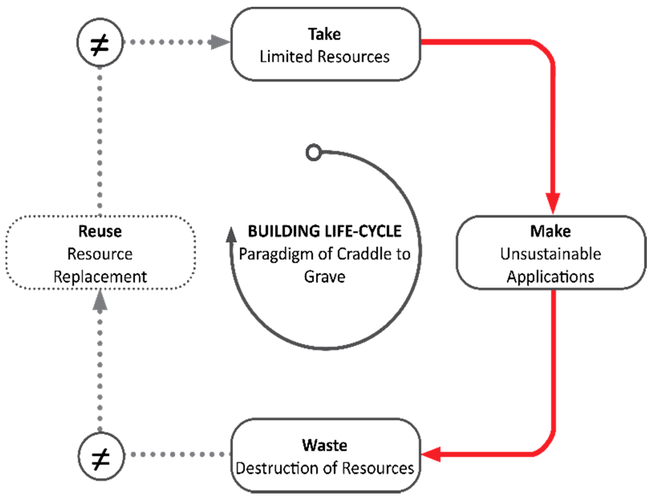
The constant adaptation to social influences and to environmental constellations are important factors to consider when planning contemporary architecture. Man-made influences on building culture have always been passively influenced by climatic environmental conditions. As a result, the architectural language of form is constantly evolving, and innovative design processes are developed. The cradle to grave paradigm, which is often applied by the building industry, is based on a raw material consumption of “take, make and waste” [
1]. In Europe, only 50% of the raw materials used by the construction industry are recyclable [
2]. On a global scale, the construction sector is responsible for 36% of the world’s energy consumption and for almost 45% of the world’s resource consumption. The usage of conventional raw materials such as steel, aluminum, and concrete causes an enormous CO
2 emission of almost 40%, of which 8% is due to the usage of cement [
3,
4,
5,
6] (
Figure 1).
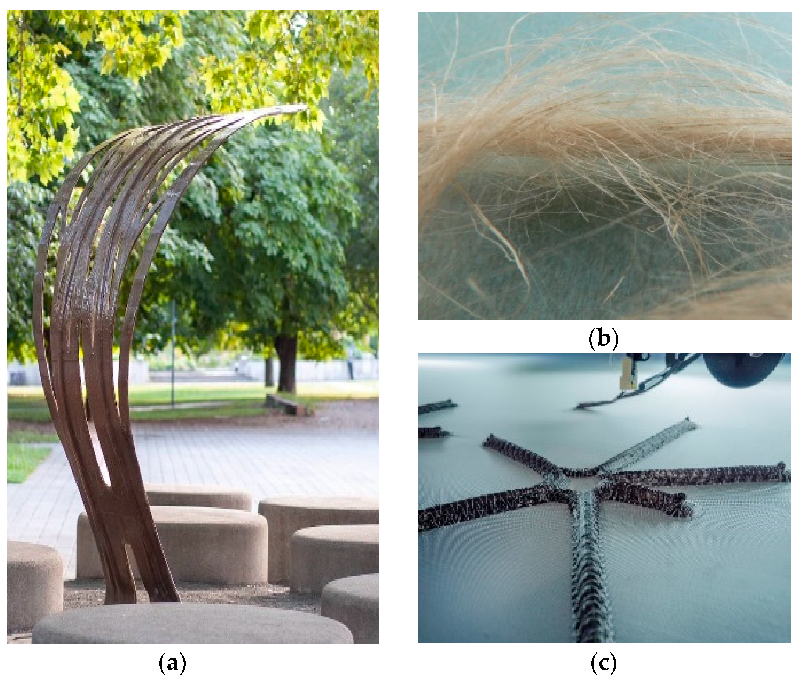
The resulting change in global climatic conditions is forcing architects to develop new approaches of design thinking. The combination of innovative materials, bio-based engineering principles and new fabrication techniques is a promising way to ensure more sustainable construction methods. The architectural use of polymer composites has a great potential for optimizing lightweight, structural and non-structural applications such as canopies, pavilions, or facade elements (
Figure 2) [
7,
8,
9,
10,
11,
12,
13,
14,
15,
16].
The possibility of custom configuration of composite components enables the creation of tailor-made material compositions. The adaptation of the fiber orientation in load-bearing geometries according to applied load cases leads to extraordinary performance qualities. The sustainability in structural end-use applications increases through biological building materials. Natural fiber-reinforced polymer composites (NFRP) are already well established in automotive and aircraft industry. They represent a promising solution for future architectural applications.
The integration of biomimetic principles, such as topology optimization enables innovative architectural lightweight constructions. This principle was here applied as a reference for load-bearing structures distributing material paths according to the axiom of uniform stress, which is of great importance and relevance in this project. In addition, the use of well-established fabrication techniques from the aerospace industry can help to revolutionize architectural design, which was as well approached.
The presented work is the result of close cooperation between architects and engineers in the fields of architecture, aircraft construction and polymer research. The workflow of knowledge and expertise exchange as well as the close collaboration of the research fields are major factors in the development of the project. The use of NFRPs, combined with the application of computational design and digital optimization techniques, were decisive for the successful realization of the architectural lightweight structure through state-of-the-art digital additive fabrication techniques.
Case Study
The project’s core is the material-appropriate application of a recyclable natural fiber-reinforced polymer composites to a load-bearing structure using the methods of topology optimization and fiber orientation according to the occurring principal stress trajectories. The outcome highlights the design-related potential of analyzing the properties and restrictions of biological role models, fiber composites and the combination of digital and physical manufacturing methods to find innovative and sustainable architectural lightweight solutions. The segmental design bypasses the size restrictions of TFP production and transfers the use of load-optimized thermoset plant-based NFRP composites produced by TFP to an architectural scale. The fiber path orientation according to the principal stress directions in continuous fiber-reinforced plastics minimizes resource consumption and maximizes load carrying capacity.
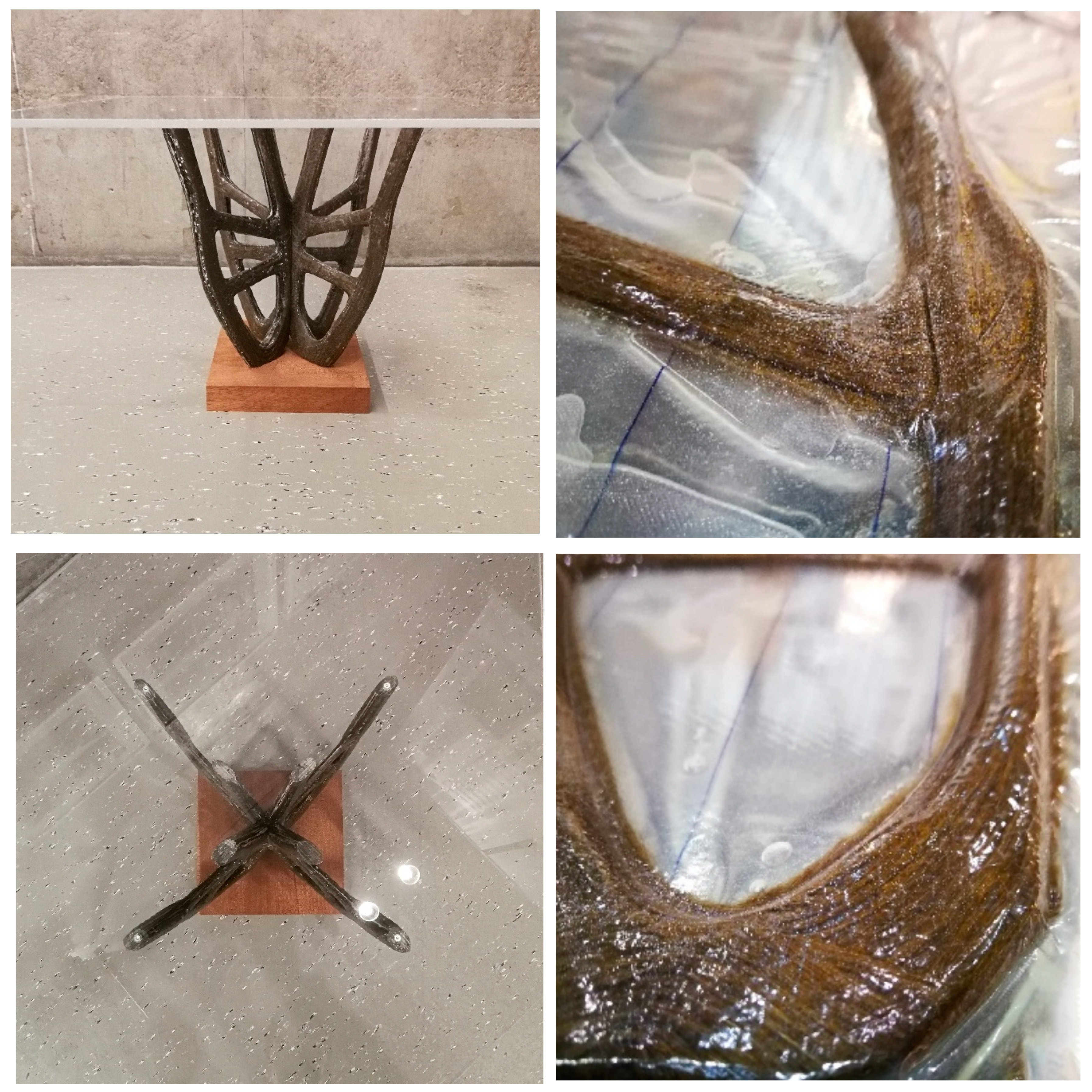
The 4 m high and 4 m wide supporting structure has a total volume of 2.15 m3 and consists of four identical, double-curved branching elements. They are rotationally symmetric arranged and connected centrally by additional filament winding. The element can be used as a fixed or temporary load-bearing structure for street furniture, facade parts, or as an installation for events and museums.
Its morphology is derived from a generative topology optimization process consisting of parameter-driven design and optimization simulations (Rhinoceros 3D, Grasshopper, Fusion 360, ANSYS). Secondary manual design adjustments create a load-optimized and material-efficient geometrical design. The structural design and Finite Element (FE) modelling of the variable axial fiber patterns were carried out using two software tools developed for this purpose (EDOPath, EDOStructure). The computational approach enabled the division of the four branches of the structure into six laminate layers. They consist of individual load-optimized variable-axial fiber patterns manufactured using TFP technology. Due to the relatively high strength related to its density, a natural fiber-reinforced polymer (NFRP) based on flax fibers was chosen. The laminates were fabricated using a Tajima multi-head TFP machine type TLMX-T02 and then finished into their final form using resin infusion process and vacuum pressing (VARTM) [
7]. Due to given restrictions of the machining areas of the fabrication technology, a demonstrator in scale 1:10 was built.
2. Materials and Methods
The project started following the design philosophy: “Materials as a Design Tool” [
19] combined with a synthesis of primarily inductive and partially deductive methodology. The aim was to further investigate the applicability of Tailored Fiber Placement in the field of architecture and how the material-appropriate application of NFRP can contribute to structural optimization and increase the sustainability level as once indicated using another material development in architecture from the same BioMat group [
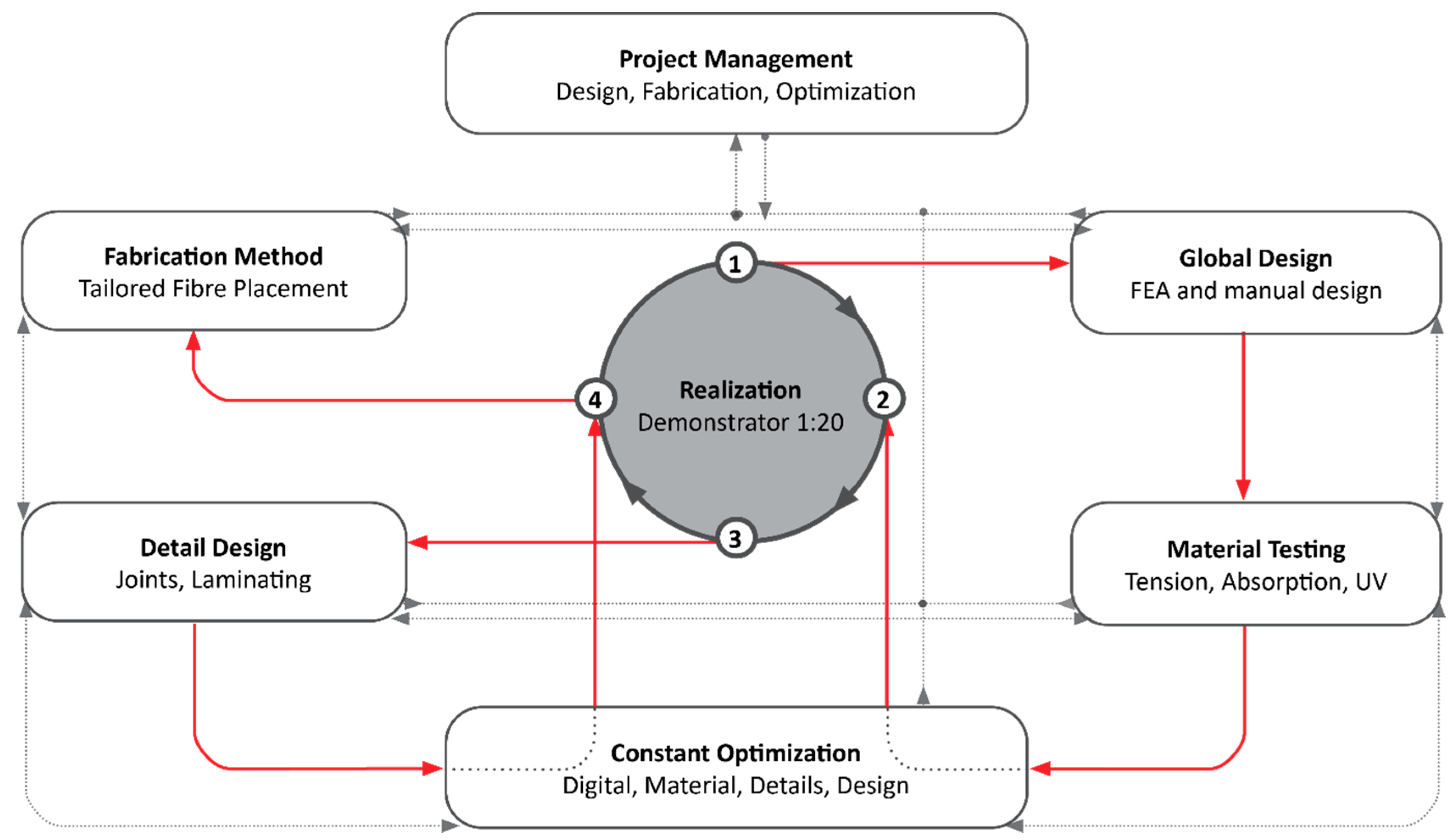
11]. The iterative design process included manual and digital computational design, parameter driven optimization and digital fabrication. In that sense, the analysis of the biomimetic topology optimization, the modification of specific material properties and the application potentials of additive fabrication technologies were applied. For the constant optimization of the workflows, a continuous exchange of knowledge between the participants took place (
Figure 3). The final prototype was evaluated through simulations and physical performance tests, then modified accordingly and constructed as a 1:10 demonstrator.
2.1. Analysis Criteria
To evaluate the obtained results of the prototype construction, functional and performative design criteria were restricted to three design parameters:
Structural optimization and material reduction through fiber orientation;
Material-appropriate application of NFRP for time-efficient fabrication;
Development of a demonstrator with a minimum load capacity of 2.000 N.
These criteria have been tested, optimized, and evaluated as inputs in the engineering process. The following sections explain the results in detail to confirm the hypothesis.
The overall design objective of the presented work is the realization of an innovative material-minimizing and performance-maximizing architectural load-bearing structure and its exploration of fabrication-related geometric tolerances, materialized from recyclable thermoset NFRPs. Through the applied methodologies, topological optimization of the structure, appropriate application of customized material properties and combination of the TFP fabrication followed by filament winding was applied. The close cooperation between the engineers of the Leibniz Institute of Polymer Research Dresden e. V., the Institute for Aircraft Design, and the architects of the BioMat Department (Bio-based Materials and Materials Cycles in Architecture) located at the Institute of Building Structures and Structural Design (ITKE) at the University of Stuttgart did not only establish a novel circular design workflow, rather also provided valuable insights within the respective expertise. By means of the intelligent cross-linking of material-appropriate design (orthotropic material properties), digital optimization processes (topology optimization) and scalable design (segmental elements), the project took a cutting-edge role in the development of novel material-saving, high-performance and environmentally friendly load-bearing structures, which was the set hypothesis, then validated through the 1:10 mock-up.
2.2. Natural Fiber-Reinforced Polymer Composites (NFRP)
Flax fibers about 2.5–6 cm long were applied that have been joint to 50–90-cm-long yarns through textile engineers and processed into continuous fiber rovings prior to our application [
18,
20]. Flax fibers were chosen, due to the global increase of its economic and ecologic importance, their CO
2 neutral life cycle and its relatively low energy consumption in production processes [
21,
22]. Within the presented work a 1000-Tex flax fiber roving was used (distributor, Group Depestele, Bourguebus, France). The applied thermoset matrix system as provided from Hexion Stuttgart GmbH was EPIKOTE Resin RIMR 135 and the curing agent was EPICURE RIMH 137 [
23].
The fiber placement paths mimicked the fibrous structure of plants, which dissipated loads anisotropically along their principal stress axes [
24]. Strength, stiffness and flexibility in relation to density of flax fibers are comparable with industrial man-made endless fibers, e.g., glass fibers [
25,
26]. A possible end-of-life scenario is the grinding of the NFRP and its reintroduction into manufacturing processes. With the possibility of thermal recycling via incineration, energy costs can be partially regained. The high anisotropy and the resulting load-efficient qualities allowed the applied materials to be suitable for architectural freeform structures. In addition, the polymer-encapsulated fibers have already stored CO
2 during growing before being applied in the material technical cycle as a building material.
2.3. Biomimetics and Topology Optimization
Biomimetics is a growing science branch in which diverse investigations and scientific developments take place including studying the properties of evolutionary proven functions, proportions and patterns of natural systems. It offers an inspiring framework that allows the development of new conceptual designs and the integration in innovative manufacturing techniques. Novel materials and experimental construction principles can be applied into architectural applications through a further technical optimization [
27,
28,
29].
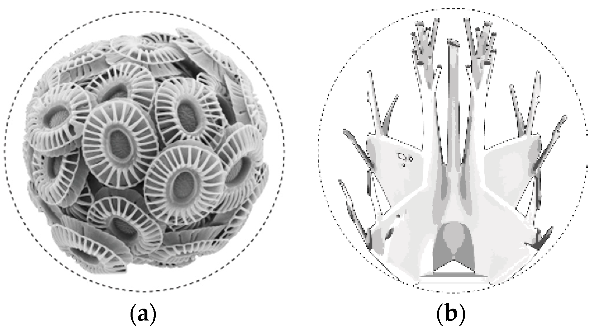
In the project, a unicellular microplankton was chosen as the biological role model, from which technical solutions like setting the optimized fiber paths have been “mimicked” and abstracted. The microorganisms that are composed of modular components, so-called coccoliths, have special geometries of individual particles that are determined by environmental conditions such as protective functions and stresses [
30,
31]. The principle of topology optimization allows a minimal material distribution. This concept was abstracted and applied in the project (
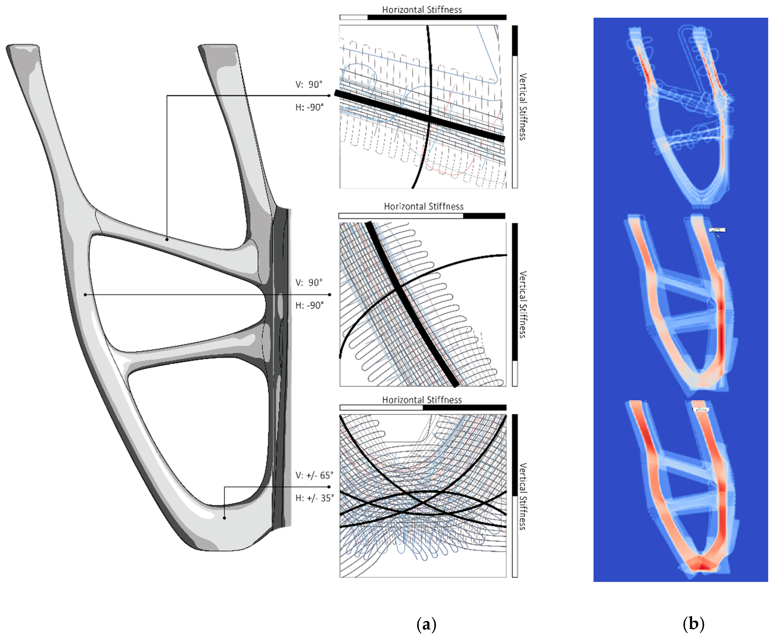
Figure 4).
The principle of topology optimization is the central link between design, biomimicry and digital form finding processes. It enabled the creation of more stable and lighter supporting structures. The parameter-determined design process enabled the generation of automated form finding based on the axiom of uniform stress. This FEM process applies boundary conditions such as material properties, loads, supports and restrictions based on a defined domain. In iterative steps solution-oriented geometries are generated, following the “axiom of uniform stress” [
32,
33,
34]. The enormous morphological diversity of the geometry proposals was evaluated and used design-orientated as a creative foundation for the project’s structural composition.
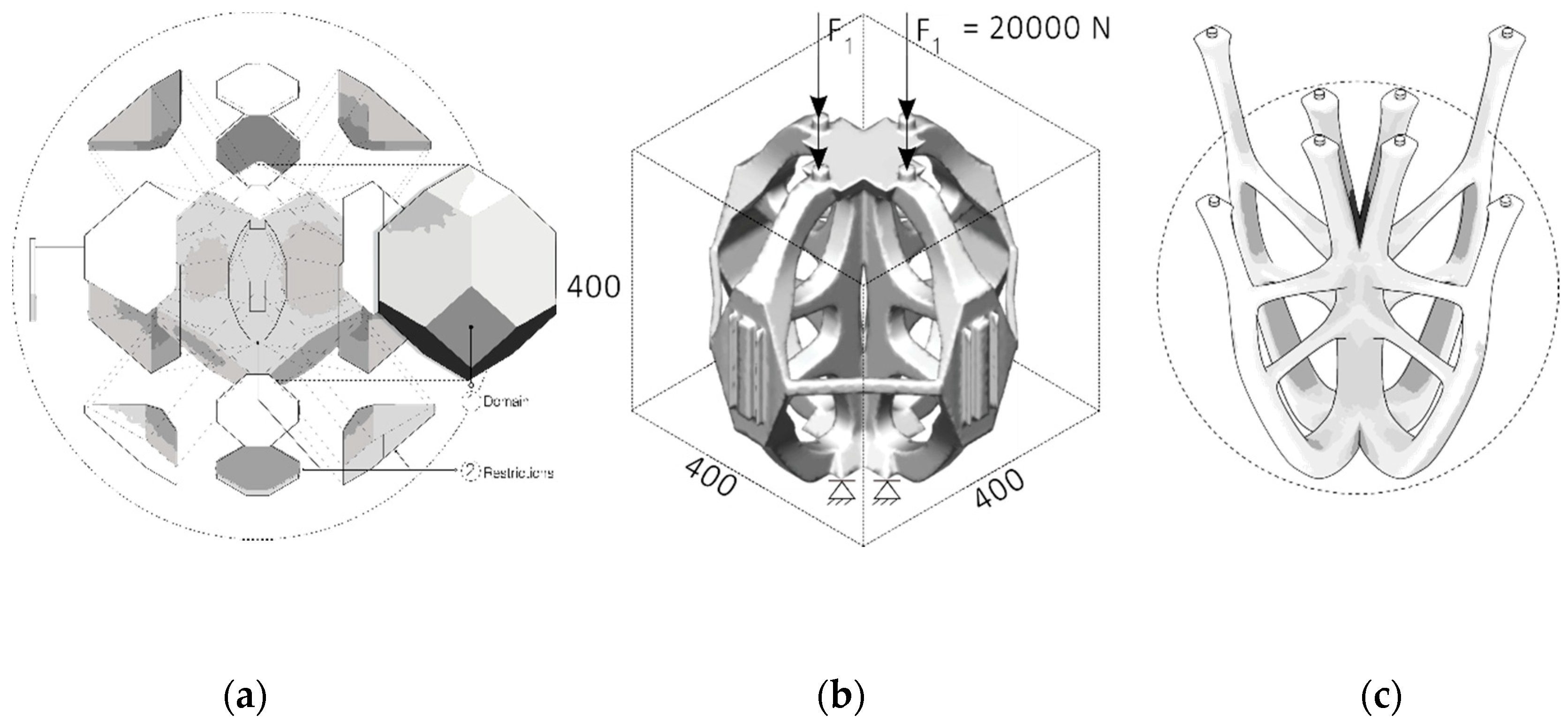
Topology Optimization
The topology-optimized design consisted of four identical elements, which together formed a double-symmetrical structure. To determine the global geometry, load-specific fiber orientation, advantages of FEM and further manual design adjustments were applied. Assigning the following parameters were the baseline conditions that were set for the simulative form finding process: The domain (solid 3-D hexagonal solid, 4 × 4 × 4 m, with geometric restriction areas); the supports and loads (principal stress axis generation); materials of investigation (epoxy resin, MDF, aluminum, steel) (
Table 1).
The workflow was divided into three main design phases:
Phase: Generative design—Material investigations and FEM-design of draft shape concepts—(Commercial software used: Autodesk Fusion 360 + material library, T-Splines) (
Figure 5);
Phase: Fiber Design—FEM to generate orthotropic, load-specific fiber paths and laminates; geometry adjustment through thickness distribution dependent on fiber patterns; automatic mold generation. (Software used: EdoStructure, EdoPath developed by IPF);
Phase 3: Final Design—Fabrication and visually dependent fiber path and mold adaptation. (Software used: Rhinoceros 3D, T-Splines, Adobe Illustrator).
2.4. Design and Manufacturing Process
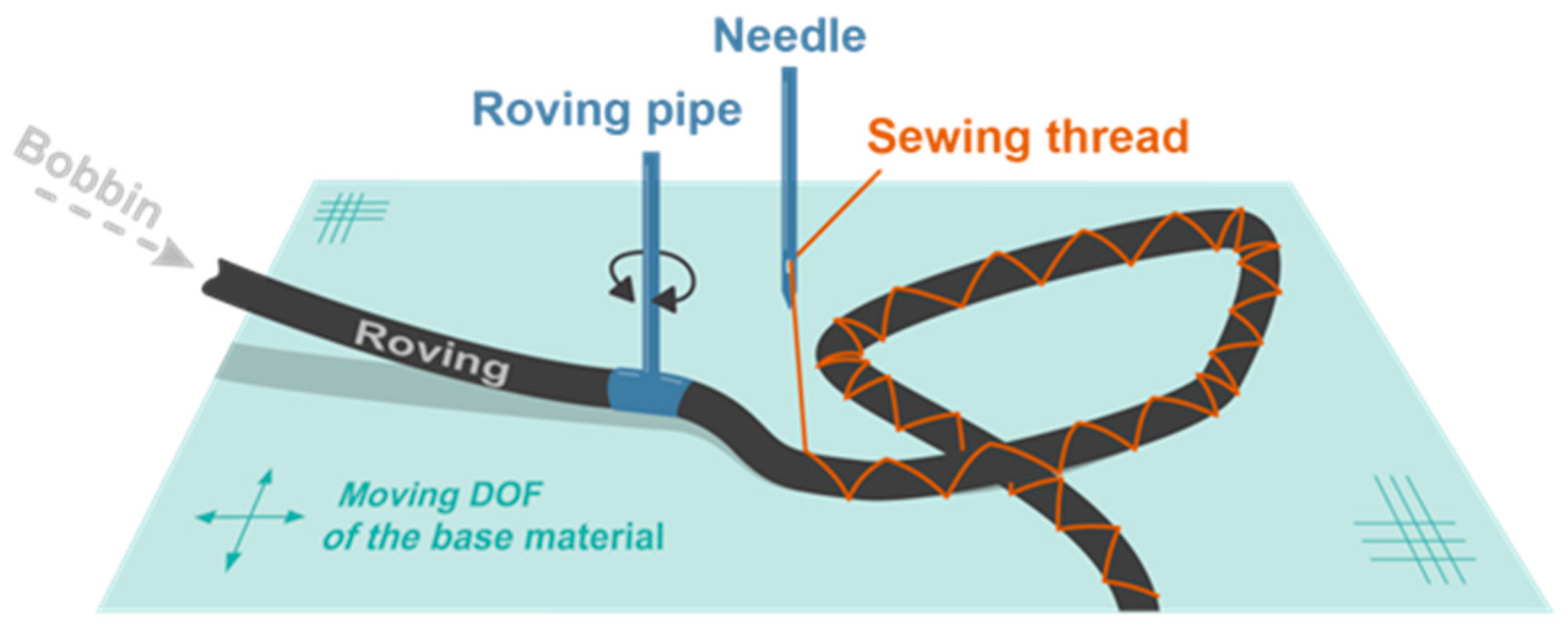
2.4.1. Tailored Fiber Placement
Tailored Fiber Placement (TFP) is an embroidery-based preform additive manufacturing technique that allows a flexible orientation of any fiber roving (e.g., carbon, glass, aramid). The TFP technology was invented at the Leibniz-Institut für Polymerforschung Dresden e. V. [
36]. With this technology a continuous roving is placed along programmable curves within the plane (2D) and fixated by a stitching yarn onto a flat textile base material using a double locked stitch in a zig-zag stitch pattern (
Figure 6). The roving is deposited following a pre-defined path by rotating the roving pipe and moving the base material in two perpendicular directions [
37]. Due to the technological degrees of freedom and the relatively high placement speed of up to 5 m/min per head, TFP is well suited for producing variable-axial (VA) composites which are also known as variable-stiffness (VS) and variable angle-tow (VAT) composites [
38].
2.4.2. Fiber Path Pattern Generation
Form finding using Tailored Fiber Placement enables the production of precisely tailored preforms. The automatic preform generation economizes material consumption and minimizes the production of unusable waste materials compared to established Fiber processing techniques. The capability of the TFP technology to produce preforms based on continuous roving materials was assessed by Mattheij et al. [
34]. The application of TFP to produce preforms with a curvilinear Fiber pattern were investigated on open-hole tension plates by Crothers et al. [
38], Gliesche et al. [
39], Temmen et al. [
40] and Aschenbrenner et al. [
41], and Spickenheuer et al. [
42]. Spickenheuer et al. developed a design tool to numerically derive fiber paths along principal stress directions [
42]. Spickenheuer et al. [
43,
44] and Albers et al. [
45] combined topology optimization with an appropriate fiber design for producing TFP-based structures. Uhlig et al. [
36] developed a parametrical three-dimensional representative unit cell (RUC) based on Finite Elements of TFP based FRP. The representative RUC reflects the TFP specific morphology and allows a better estimation of the resulting material properties depending on the applied TFP parameter. Uhlig et al. [
37] experimentally investigated the influence of Tailored Fiber Placement (TFP) processing-related parameters on in-plane waviness and fiber volume content of Unidirectional Carbon Fiber-Reinforced Plastic (UD-CFRP) Composites. Recently, Bittrich et al. [
46] proposed a novel framework for optimizing variable axial composites.
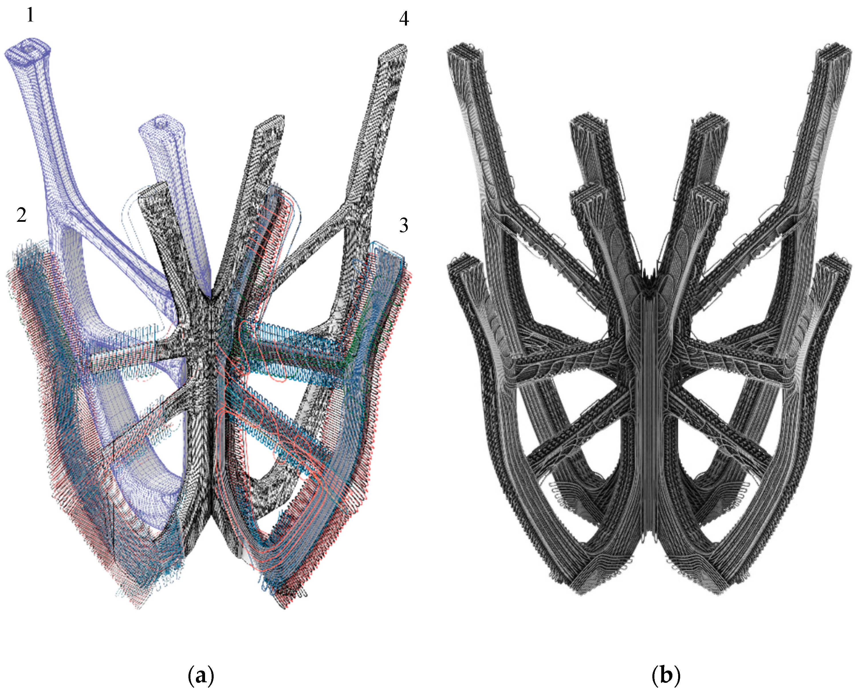
After topology optimization, the geometry was segmented to produce fiber paths in principle from unwrappable single or double curved shell structures. Subsequently, this shell structure was meshed with a Finite Element (FE) software (Ansys). The creation of the fiber paths adapted to the defined load case was performed with the software “EDOStructure”, a tool especially developed for the design of VA or VAT FRP laminates. In this step, the FE-mesh was imported in “EDOStructure” and the Fiber paths were defined according to the principal stress directions. The symmetrical element consisted of two mirrored components. The software generated three laminate layers (substrate layer, 1st principal stress layer, 2nd principal layer) per component with 2–5 mm cross-sections. Each layer has an individual geometry that is optimized for the respective load absorption. The resulting thickness distribution determines the structural integrity, volume, and surface properties of the element.
As the automatically generated fiber patterns did not meet the aesthetic requirements, they were redesigned in Rhinoceros (
Figure 7) and re-imported into the “EDOStructure” software. EDOStructure automatically calculates the resulting thickness distribution of the created line pattern based on the used defined material data and takes over the draping process. For an analysis of the component properties EDOStructure creates a 3D FE model with retention of all single layer information. This data set was imported into commercial FE software solutions (Ansys, Autodesk Fusion 360), and the component performance was evaluated in a stress and strain analysis after applying the appropriate boundary conditions and correct material data. When the component properties meet the requirements in the FEA prior to the production of the preform, the generation of the stitch data set for the TFP device is required. Therefore, the software EdoPath was used in this work. EdoPath creates the stitch data automatically based on the Fiber pattern as a *.dxf file. Among others, the average stitch width and stitch distance for each individual layer of the Fiber pattern was set.
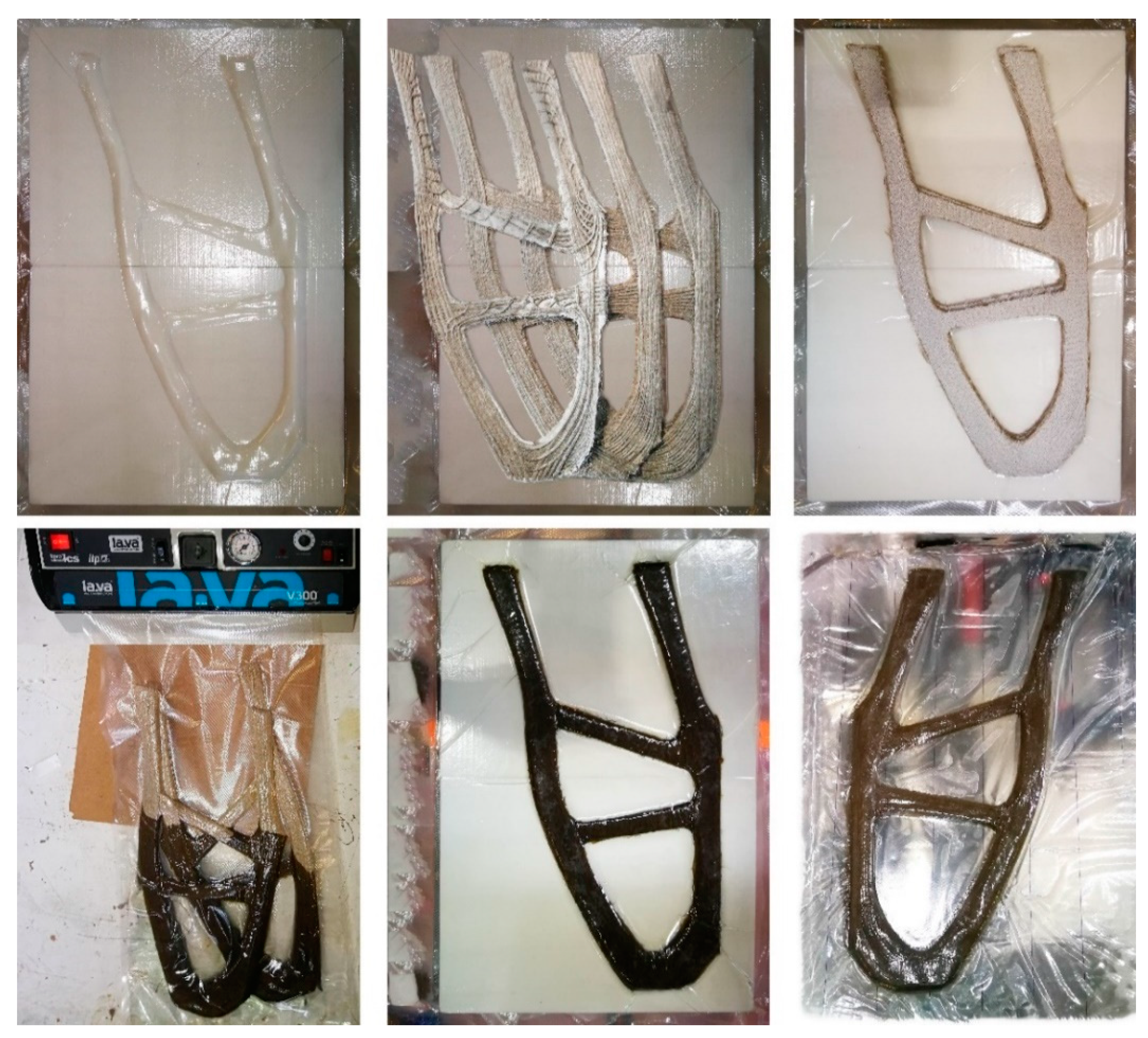
2.4.3. Physical Manufacturing Process
The manufacturing of the preform was done with the following process parameters (
Table 2). A Tajima 4 head TFP machine Type TLMX-T02 has been used (
Figure 8). The machining of the used flax roving did not show any problems or collisions.
There was no loosing of stitching or failures like blocking of the feeding bobbin. A higher stiffness in the material compared to glass fiber could be observed. It can also be stated that the maximum preform thickness of 10mm of the TFP process has not been reached. The maximum thickness of preforms is 5 mm (sub- preform No.3) or less. To analyze the maximum thickness which can be reached with the used flax material, further trials are necessary in future work.
2.4.4. Vacuum Infusion
After TFP production and trimming of the residual substrate textile, the preforms were infiltrated by means of the Vacuum Assisted Resin Infusion (VARI). For this purpose, commercially available polyethylene vacuum foils were cut as needed and sealed using a vacuum pump (Model P3 from R&G Faserverbundwerkstoffe, max. 55 l/min. at 0.900 bar). The resin compound used, with a mixing ratio of 100:30, was EPIKOTE Resin MGS RIMR 135 with EPIKURE Hardener RIMH 137, manufactured by Hexion Inc. The fiber volume ratio of the preforms consists of 30/70, which required an optimum quantity of approx. 130 g resin per preform (p. P) (
Table 3).
To prevent the formation of air bubbles and ensure complete infiltration, 165 g p.P. were used. During the compression process of the resin-impregnated preform, about 30 g of excess resin escaped, resulting in an average weight of 218 g per cured preform. The total manufacturing time of one component is approx. 30 min, with a subsequent curing time of 48 h at room temperature (
Figure 9). The table present the results obtained.
2.4.5. Assembly
The designed supporting structure consisted of 4 double-symmetrical elements. A Plexiglas board was fixed on its top and the whole demonstrator was anchored in a resin foundation. Each element consisted of two mirrored preforms, which were sanded along their mirror side, glued, and pressed for 30 min. The 45° angle cut of the preform middle edge enabled a symmetrical composition of the four elements at their centers. All elements were reinforced by an adhesive connection and an additional fiber winding.
4. Discussion
The aim of the project was, on the one hand, to determine the potential for performance enhancement of architectural lightweight structures by material-appropriate application of plant-based natural fibers applied as a reinforcing agent within a biocomposite component using biomimetic topology-optimization scenarios. On the other hand, such developments highlight further possibilities of applying quick renewable resources in the building industry to reduce the construction ecological footprint using additive manufacturing techniques like the chosen tailored fabrication by Tailored Fiber Placement (TFP), adapted from automotive and aircraft design industries to the building construction one. The accomplished combination of methods demonstrates an ultra-lightweight load-bearing mock-up structure capable of bearing approximately 200 times its own weight. The innovative workflow and the interdisciplinary work division, as well as the use of innovative digital fabrication techniques and bio-based materials, is a considerable inspiration for future sustainable architectural practices and engineering design approaches. These workflows establish a novel possibility that contributes to the performance increase of supporting structures by adapting material tectonics. This consists of an intersectional design process of digital and physical optimization, e.g., generation of orthotropic materials or tailoring of preforms.
Embroidered on a glass fiber substrate, TFP preforms are given their characteristic topology after shape cutting, resin injection and compression molding to maximize load bearing capacity and structural integrity. The stress related thickness distribution of the fibrous elements and the surface patterns create objects with a natural visual richness. The morphology recalls a classic dendrological structure found in tree branches or root cross-sections and transforms it into new material-specific design expressions (
Figure 11).
The relatively short development time of approx. five months did not allow the collection of all further relevant data sets. The obtained data (structural performance, stiffness, material properties, digital and physical optimization processes, etc.) are prototype related. Due to the lack of test series and manual post-processing, this outcome cannot be considered as a fully accurate database for scientific applications by NFRP and TFP. The results should rather be seen as an academic guideline and proof for other means towards designing high-performance sustainable structures using diverse digital approaches and systems responsive to our digital era. Generally, it can be stated, that the knowledge obtained from this development provides satisfactory results that can be used as a guideline for potential sequel projects. In addition, these projects could benefit from a bigger integration of interdisciplinarity with a focus on automation of assembly processes and adaptation of the building materials. Automation processes are already being investigated to bypass time-consuming manual operations. This does not only reduce production time but also improves performance through more precise and repetitive workflows. In this context, it is conceivable to replace conventional fiber rovings with prepreg-rovings.
Further weight reduction and larger structures could be designed with more sophisticated modular segments. Specialized roving modifications, fiber path layouts and alternative matrices could contribute to this. The in-depth knowledge of the properties of automated building processes and sustainable materials could ultimately help to transfer new architectural design concepts to the building construction industry and make them more sustainable.
Author Contributions
T.S., H.D., K.U. and B.G. contributed their expertise to this paper. The project concept was developed by T.S. and supervised by H.D. throughout the methodology, design process, and digital and computational design optimizations, which were executed collaboratively by K.U. and T.S.; validations and formal data analyses were carried out by T.S., K.U. and B.G.; the physical fabrication and prototype construction was executed by T.S. and B.G. Visualizations were designed by T.S.; original draft preparation, T.S.; review and editing, H.D., K.U. and B.G. The project was supervised by H.D. and originated from the cooperation channel created by her (BioMat) with (IPF) and (IFB) teams. All authors have read and agreed to the published version of the manuscript. P.M. and S.C. (IFB Team) reviewed the paper and supervised the TFP fabrication process, providing the needed infrastructure.
Funding
This research received no external funding.
Acknowledgments
The work presented here represents main parts of the first author-master’s thesis of architecture, developed in the winter semester 2019/2020, under supervision of the second co-author H.D. (BioMat director), tutored by J.P. (BioMat Team), K.U. (IPF Team) and B.G. (IFB Team). It is the result of a collaboration between the department BioMat (Biobased Materials and Materials Cycles in Architecture) located at Institute of Building Structures and Structural Design (ITKE) and the Institute of Aircraft Design (IFB) at the University of Stuttgart as well as the Leibniz Institute of Polymer Research (IPF) in Dresden. The authors would also like to show their gratitude to Axel Spickenheuer and Lars Bittrich (IPF Team) for the intense consultancy, opportunity to access machines and software tools. The 1000Tex flax rovings were provided by Group Depestele, Teillage Vandecandelaere 5, rue de l’église, 14 540 Bourguebus, France. The resin was provided by Hexion Stuttgart GmbH.
Conflicts of Interest
The authors declare no conflict of interest.
References
- Scheelhaase, T. Zukunft: Klimaschutz Kompostierung; Environmental Protection Encouragement Agency, PEA Internationale Umweltforschung GmbH: Hamburg, Germany, 2009. [Google Scholar]
- Bio Intelligence Service. Service Contract on Management of Construction and Demolition Waste SR1. Final Report Task 2. European Commission (DG ENV). 2011. Available online: https://ec.europa.eu/environment/waste/pdf/2011_CDW_Report.pdf (accessed on 15 December 2020).
- Lehne, J.; Preston, F. Making Concrete Change. Innovation in Low-Carbon Cement and Concrete; Chatham House for the Royal Institute of International Affairs: London, UK, 2018; ISBN 978-1-78413-272-9. [Google Scholar]
- Abergel, T.; Dean, B.; Dulac, J. Towards a Zero-Emission, Efficient, and Resilient Buildings and Construction Sector: Global Status Report 2017; UN Environment International Energy Agency: Paris, France, 2017. [Google Scholar]
- Pomponi, F.; Moncaster, A. Embodied carbon mitigation and reduction in the built environment—What does the evidence say? J. Environ. Manag. 2016, 181, 687–700. [Google Scholar] [CrossRef] [PubMed] [Green Version]
- Herczeg, M.; McKinnon, D.; Milios, L.; Bakas, I.; Klaassens, E.; Svatikova, K.; Widerberg, O. Resource Efficiency in the Building Sector. Final Report. Available online: https://ec.europa.eu/environment/eussd/pdf/Resource%20efficiency%20in%20the%20building%20sector.pdf (accessed on 9 July 2020).
- Dahy, H.; Petrs, J.; Baszynski, P. Design and Fabrication of two 1:1 Architectural Demonstrators based on Biocomposites from Annually Renewable Resources displaying a Future Vision for Sustainable Architecture. In Fabricate 2020: Making Resilient Architecture; Burry, J., Sabin, J., Sheil, B., Skavara, M., Eds.; UCL Press: London, UK, 2020; ISBN 9781787358119. [Google Scholar]
- Rihaczek, G.; Klammer, M.; Başnak, O.; Petrš, J.; Grisin, B.; Dahy, H.; Carosella, S.; Middendorf, P. Curved foldable tailored fiber reinforcements for moldless customized bio-composite structures. Proof of Concept: Biomimetic NFRP Stools. Polymers 2020, 12, 2000. [Google Scholar]
- Costalonga Martins, V.; Cutajar, S.; van der Hoven, C.; Baszyński, P.; Dahy, H. FlexFlax Stool: Validation of Moldless Fabrication of Complex Spatial Forms of Natural Fiber-Reinforced Polymer (NFRP) Structures through an Integrative Approach of Tailored Fiber Placement and Coreless Filament Winding Techniques. Appl. Sci. 2020, 10, 3278. [Google Scholar] [CrossRef]
- Dahy, H. Natural Fibre-Reinforced Polymer Composites (NFRP) Fabricated from Lignocellulosic Fibres for Future Sustainable Architectural Applications, Case Studies: Segmented-Shell Construction, Acoustic Panels, and Furniture. Sensors 2019, 19, 738. [Google Scholar] [CrossRef] [Green Version]
- Horn, R.; Dahy, H.; Gantner, J.; Speck, O.; Leistner, P. Bio-Inspired Sustainability Assessment for Building Product Development—Concept and Case Study. Sustainability 2018, 10, 130. [Google Scholar] [CrossRef] [Green Version]
- Dahy, H. Efficient fabrication of sustainable building products from annually generated non-wood cellulosic fibres and bioplastics with improved flammability resistance. Waste Biomass Valoriz. 2019, 10, 1167–1175. [Google Scholar] [CrossRef]
- Dahy, H. Biocomposite materials based on annual natural fibres and biopolymers—Design, fabrication and customized applications in architecture. J. Constr. Build. Mater. 2017, 147, 212–220. [Google Scholar] [CrossRef]
- Dahy, H.; Petrs, J.; Bos, D.H.; Baszynski, P.; Habraken, A.P.H.W.; Teuffel, P.M. BioMat Pavilion 2018: Development, Fabrication and Erection of a Double Curved Segmented Shell from Biocomposite Elements. In Proceedings of the IASS Annual Symposium 2019—Structural Membranes 2019 Form, Barcelona, Spain, 7–10 October 2019. [Google Scholar]
- Dahy, H.; Petrs, J.; Baszynski, P. Experimental Biocomposite Pavilion: Segmented Shell Construction—Design, Material Development and Erection. In Proceedings of the ACADIA 2019: The 39th Annual Conference of the Association for Computer Aided Design in Architecture, Austin, TX, USA, 21–26 October 2019. [Google Scholar]
- Dahy, H. Biocomposites for Architectural Applications based on the Second Generation of Natural Annual Renewable Resources. In Proceedings of the Conference Proceedings: SBE16 Hamburg. International Conference on Sustainable Built Environment Strategies—Stakeholders—Success Factors, Hamburg, Germany, 7–11 March 2016. [Google Scholar]
- Innfa GmbH. Bango. Available online: https://www.bango-music.com/ (accessed on 11 August 2020).
- Carus, M. Studie zur Markt- und Konkurrenzsituation bei Naturfasern und Naturfaser-Werkstoffen. In Gülzower Fachgespräche; Fachagentur Nachwachsende Rohstoffe e.V. (FNR): Gülzow-Prüzen, Germany, 2008; p. 157. [Google Scholar]
- Dahy, H. ‘Materials as a Design Tool’ Design Philosophy Applied in Three Innovative Research Pavilions Out of Sustainable Building Materials with Controlled End-Of-Life Scenarios. Buildings 2019, 9, 64. [Google Scholar] [CrossRef] [Green Version]
- Alves, C.; Ferrão, P.M.C.; Silva, A.J.; Reis, L.G.; Freitas, M.; Rodrigues, L.B.; Alves, D.E. Ecodesign of automotive components making use of natural jute fiber composites. J. Clean. Prod. 2010, 18, 313–327. [Google Scholar] [CrossRef]
- Le Duigou, A.; Davies, P.; Baley, C. Environmental Impact Analysis of the Production of Flax Fibres to be Used as Composite Material Reinforcement. J Biobased Mat. Bioenergy 2011, 5, 153–165. [Google Scholar] [CrossRef]
- Goutianos, S.; Peijs, T. The Optimisation of Flax Fibre Yarns for the Development of High-Performance Natural Fibre Composites. Adv. Compos. Lett. 2003, 12, 237–242. [Google Scholar] [CrossRef] [Green Version]
- Hexion Inc. Momentive Specialty Chemicals; Hexion Inc.: Columbus, OH, USA, 2014. [Google Scholar]
- Singleton, A.C.N.; Baillie, C.A.; Beaumont, P.W.R.; Peijs, T. On the mechanical properties, deformation and fracture of a natural fibre/recycled polymer composite. Compos. Part B Eng. 2003, 34, 519–526. [Google Scholar] [CrossRef]
- Goutianos, S.; Peijs, T.; Nystrom, B.; Skrifvars, M. Development of Flax Fibre based Textile Reinforcements for Composite Applications. Appl. Compos. Mater. 2006, 13, 199–215. [Google Scholar] [CrossRef] [Green Version]
- Hausladen, G.; de Saldanha, M.; Liedl, P. Climateskin. Building-Skin Concepts That Can Do More with Less Energy; Birkhaeuser: Basel, Switzerland; Boston, MA, USA, 2008; ISBN 3764377259. [Google Scholar]
- Zari, P. Biomimetic Approaches to Architectural Design for Increased Sustainability. In Proceedings of the Sustainable Building (SB07) Regional Sustainable Building Conference, Auckland, New Zealand, 14–16 November 2007. [Google Scholar]
- Benyus, J.M. Biomimicry: Innovation Inspired by Nature; William Morrow: New York, NY, USA, 1997; ISBN 9780688136918. [Google Scholar]
- Langer, G.; de Nooijer, L.J.; Oetjen, K. On the role of the cytoskeleton in coccolith morphogenesis: The effect of cytoskeleton inhibitors. J. Phycol. 2010, 46, 1252–1256. [Google Scholar] [CrossRef] [Green Version]
- Gibbs, S.J.; Sheward, R.; O’dea, S.; Higgins, D. Searching for cells: The potential of fossil coccospheres in coccolithophore research. J. Nannoplankton Res. 2014, 34, 5–21. [Google Scholar]
- Bendsøe, M.P.; Sigmund, O. Topology Optimization. Theory Methods and Applications, 2nd ed.; Springer: Berlin/Heidelberg, Germany, 2004; ISBN 9783540429920. [Google Scholar]
- Großmann, U. Leichtbau und Designfindung. Available online: http://www.iwf-ug.de/designfindung.html (accessed on 7 September 2020).
- Tanskanen, P. The evolutionary structural optimization method: Theoretical aspects. Comput. Methods Appl. Mech. Eng. 2002, 191, 5485–5498. [Google Scholar] [CrossRef]
- Mattheij, P.; Gliesche, K.; Feltin, D. Tailored Fiber Placement-Mechanical Properties and Applications. J. Reinf. Plast. Compos. 1998, 17, 774–786. [Google Scholar] [CrossRef]
- Taylor, A.R.; Brownlee, C.; Wheeler, G. Coccolithophore Cell Biology: Chalking Up Progress. Ann. Rev. Mar. Sci. 2017, 9, 283–310. [Google Scholar] [CrossRef] [Green Version]
- Uhlig, K.; Tosch, M.; Bittrich, L.; Leipprand, A.; Dey, S.; Spickenheuer, A.; Heinrich, G. Meso-scaled finite element analysis of fiber reinforced plastics made by Tailored Fiber Placement. Compos. Struct. 2016, 143, 53–62. [Google Scholar] [CrossRef]
- Uhlig, K.; Bittrich, L.; Spickenheuer, A.; Almeida, J.H.S. Waviness and fiber volume content analysis in continuous carbon fiber reinforced plastics made by tailored fiber placement. Compos. Struct. 2019, 222, 110910. [Google Scholar] [CrossRef]
- Crothers, P.J.; Drechsler, K.; Feltin, D.; Herszberg, I.; Bannister, M. The Design and Application of Tailored Fibre Placement. In Proceedings of the 11th International Conference on Composite Materials, Gold Coast, Australia, 14–18 July 1997; pp. 1–10. [Google Scholar]
- Gliesche, K. Application of the tailored fibre placement (TFP) process for a local reinforcement on an “open-hole” tension plate from carbon/epoxy laminates. Compos. Sci. Technol. 2003, 63, 81–88. [Google Scholar] [CrossRef]
- Temmen, H.; Degenhardt, R.; Raible, T. Tailored Fibre Placement Optimization Tool. In Proceedings of the 25th Congress of International Council of the Aeronautical Science, Hamburg, Germany, 3 September 2006. [Google Scholar]
- Aschenbrenner, L.; Temmen, H.; Genhardt, R. Tailored Fibre Placement Technology—Optimisation and computation of CFRP structures. In Proceedings of the Advances in Design and Analysis of Composite Structures—ESAComp Users’ Meeting 2007, Braunschweig, Germany, 24–25 April 2007. [Google Scholar]
- Spickenheuer, A.; Uhlig, K.; Gliesche, K.; Heinrich, G. Experimental research on open-hole tensile specimens made of carbon fibre reinforced plastics (cfrp) with an optimised curvilinear fibre pattern. In Proceedings of the COMATCOMP 09 V, International Conference on Science and Technology of Composite Materials, San Sebastian, Spain, 7–9 October 2009; pp. 1001–1004. [Google Scholar]
- Spickenheuer, A.; Uhlig, K.; Gliesche, K.; Heinrich, G. Strukturoptimierung und Herstellung von Composite-Bauteilen für den extremen Leichtbau auf Basis der Tailored Fibre Placement Technologie. In Proceedings of the 2 Konferenz für Angewandte Optimierung, Karlsruhe, Germany, 3–4 June 2008. [Google Scholar]
- Spickenheuer, A.; Uhlig, K.; Heinrich, G.; Majic, N.; Albers, A. Ansätze zur Strukturoptimierung für Faserverbundbauteile mit variabelaxialer Faserorientierung für den extremen Leichtbau. In Proceedings of the 18 Symposium Verbundwerkstoffe und Werkstoffverbunde, Chemnitz, Germany, 30 March–1 April 2011. [Google Scholar]
- Albers, A.; Majic, M.; Ottnad, J.; Spickenheuer, A.; Uhlig, K.; Heinrich, G. 3-D topology optimisation in combination with fibre alignment for composite structures manufactured by tailored fibre placement. In Proceedings of the 8th World Congress on Structural and Multidisciplinary Optimization (WCSMO-8), Lisbon, Portugal, 1–5 June 2009. [Google Scholar]
- Bittrich, L.; Spickenheuer, A.; Almeida, J.H.S.; Müller, S.; Kroll, L.; Heinrich, G. Optimizing Variable-Axial Fiber-Reinforced Composite Laminates: The Direct Fiber Path Optimization Concept. Math. Probl. Eng. 2019, 2019. [Google Scholar] [CrossRef]
| Publisher’s Note: MDPI stays neutral with regard to jurisdictional claims in published maps and institutional affiliations. |
© 2020 by the authors. Licensee MDPI, Basel, Switzerland. This article is an open access article distributed under the terms and conditions of the Creative Commons Attribution (CC BY) license (http://creativecommons.org/licenses/by/4.0/).


 ,
, 

