1. Introduction
The discovery of electrostatic attraction by William Gilbert in the 16th century [
1] sparked worldwide interest in the distortion of droplets under electrostatic force and electrically driven jets, culminating in the development of a process now known as electrospinning. In the recent past, electrospinning has emerged as the preferred method for the fabrication of nano- or microfibrous structures in textile and tissue engineering applications due to its versatility and ease of operation.
Electrospinning (or electrostatic fibre spinning) is a process that involves the stretching of a viscoelastic melt/solution into a fibre of nano- or micrometre dimensions under the driving influence of an externally applied electrostatic force. The apparatus is set up with a syringe containing a polymer solution/melt fixed at a certain distance from a grounded collector. The solution/melt is extruded through the needle tip [
2,
3,
4,
5,
6].
The polymer droplet undergoes four stages of deformation under the application of high voltage, culminating in the formation of a fibre jet (
Figure 1). When voltage is applied, charged ions accumulate around the polymer droplet. Increasing the voltage allows for the Coulombic repulsion between the ions to overcome the force of surface tension and deform the polymer droplet into what is known as the “Taylor cone.” At a critical voltage, a fine fibre jet (in either the nano- or micrometre range depending on the operating parameters) is extruded from the tip of the Taylor cone towards the grounded collector. The solvent (if present) evaporates during the time the fibre reaches the collector, resulting in the formation of a dry dense fibrous mesh [
6,
7,
8,
9].
The process of electrospinning is influenced by a number of tuneable variables commonly classed as process (applied voltage, feed/flow rate, tip-to-collector distance (TCD)), solution (concentration, conductivity, viscosity, surface tension, polymer molecular weight), ambient (temperature, humidity), and other variables. All these variables and their effects on the process and final electrospun product have been discussed in great detail throughout the literature (
Table 1). However, there is one parameter that is seldom considered—the configuration of the apparatus itself.
There are three typical electrospinning setups [
27,
28,
29,
30,
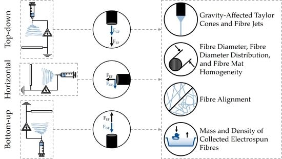
31]—horizontal, top-down, and bottom-up. In the horizontal system, the needle tip and collector are arranged in such a way that electrospinning happens parallel to the ground. Gravity, in this case, acts perpendicular to the electrical forces. In the top-down system, the fibre formation occurs in the direction of gravity. In the bottom-up system, the fibre formation occurs against the direction of gravity (
Figure 2).
To date, there are a startlingly low number of publications that even address the issue of apparatus orientation. Within this limited literature, the relative importance of gravity in different setups has been subject of considerable debate. Most research into electrospinning disregards the effect of gravity since its magnitude is negligible compared with other driving forces involved in electrospinning, and only very few analyses have taken gravity into account. However, experimental research into electrospinning setups contains evidence that the setup orientation and the effect of gravity have an influence on the final electrospun product. Until now, a clear basis of variability in differently electrospun (top-down, bottom-up, or horizontal) products has not yet been established. However, there have been some accounts of the influence of setup orientation on the electrospinning process and its outputs.
To the best of our knowledge, there is currently no review on experimental data obtained from studies comparing horizontal and vertical electrospinning. Therefore, this review aims to provide a concise but exhaustive overview on experimental insights into electrospinning in different setups. We will answer these questions: Is the orientation of the electrospinning setup a parameter to seriously consider when producing scaffolds for tissue engineering? Is further research into this area warranted? With basic research in the past, current endeavours into electrospinning are increasingly focusing on modified electrospinning setups for specialised scaffolds. At a time of significant interest in this area, we present a state-of-the-art review and hope it will fuel further research in this field.
2. State of the Art—Impact of Apparatus Orientation in Electrospinning
What we know about the impact of setup orientation on the electrospinning process is largely based on empirical data that investigate the formation of Taylor cones, morphology of jet trajectories, fibre deposition tendencies, and overall efficiency of the experimental approach. In the following subsections, qualitative and quantitative experiment-based research investigating electrospinning in different setup orientations has been detailed.
2.1. Gravity-Affected Taylor Cones and Fibre Jets
The Taylor cone is influenced by a multitude of factors—flow rate [
32,
33,
34], conductivity [
32], nozzle diameter [
32] and geometry (in coaxial spinning) [
35], viscosity [
32], polymer used [
36], surface charge [
37], charge density [
38], applied voltage [
33,
39], and solvent [
40]. Additionally, an interesting paper has investigated the effect of different setup orientations on the half-angle of the Taylor cone. Yarin et al. [
41] noted a smaller half-angle for top-down electrospinning (31°, 26°) than for bottom-up electrospinning (37.5°, 30.5°).
One of the most obvious and immediately observable differences between horizontal and vertical spinning is the shape of the extruded polymer droplet and subsequently formed Taylor cone. In vertical electrospinning, the pendant drop is perfectly spherical, and the Taylor cone forms at the centre of the needle tip. However, in the horizontal system, the polymer droplet and subsequent Taylor cone are affected by gravity and tend to sag in the vertical direction (
Figure 3). Gravity-affected Taylor cones have been reported in several studies. It has been noted that a tip-to-collector distance of more than 10 cm in a horizontal spinning setup can cause the effect of gravity on the fluid jet to become significant. This can in turn reduce effective yield because the fibre jet is dragged towards the bottom of the collector and can sometimes even be deposited below the collector [
42].
The jet trajectory in the vertical system is straight (i.e., the jet travels directly from the needle tip to the collector in a straight line). Specifically, in the bottom-up configuration, gravity plays a major role in jet initiation [
43] and seems to allow for more jet stability [
44]. In contrast, horizontal systems show parabolic jet paths. A detailed account of the occurrence of a gravity-affected Taylor cone and parabolic jet path in a horizontal setup was presented by Suresh [
28] in the electrospinning of a poly-ε-caprolactone (PCL)/gelatin blend.
In 2012, Rodoplu and Mutlu [
45] conducted a large parametric study of polyvinyl alcohol (PVA) electrospinning, part of which dealt with the effect of setup orientation (horizontal and top-down). They stated that gravity seems to have no effect on the final product because its magnitude is negligible compared with the electric field. However, there was evidence that gravity influences the actual spinning itself. For instance, the polymer droplet shape (and Taylor cone, on the application of voltage) is affected by gravity, leading to a difference in spinning parameters in the two setups. They also explained that, in the horizontal setup, the fibre jet travels a parabolic path to the collector regardless of how the Taylor cone is oriented, and the fibres are collected towards the bottom of the collector. It is plausible that some fibres were lost below the collector during this electrospinning process.
Khenoussi et al. [
46] considered the apparatus orientation when designing an electrospinning device for their experiments. They made a conscious decision to manufacture a top-down system because their first prototype, a horizontal system, showed gravity-affected jet trajectories. They considered this an imperfect setup. Since the effect of parabolic jets is not extensively studied, it is understandable that the group chose a top-down system in the interest of preserving the standardisation of their experiments.
Interestingly, the occurrence of gravity-affected jets in horizontal setups also means that the final product tends to have less artefacts, as drips and errant fibre bursts do not reach the collector due to their weight. Top-down vertical systems tend to produce slightly more imperfect electrospun products as these artefacts have nowhere to go but down to the collector. It has been noted that researchers sometimes prefer the horizontal system [
28,
47,
48] or the bottom-up system [
44,
49] to the top-down system for this specific reason, especially when the electrospinning process is not fully stable.
2.2. Fibre Diameter, Fibre Diameter Distribution, and Fibre Mat Homogeneity
In 2009, Yang et al. [
27] compared fibre diameters and fibre diameter distributions of electrospun polyvinylidene difluoride (PVDF) for a range of voltages in all three setup orientations—dubbed as shaft type (top-down), horizontal type, and converse type (bottom-up). They observed that the mean fibre diameter was lowest in the shaft type, medium in the horizontal type, and highest in the converse type. They also observed that the fibre diameter distribution was largest in the shaft type, medium in the horizontal type, and smallest in the converse type. The study finally concluded that the difference in fibre properties was due to gravity working with/strengthening (shaft), not influencing (horizontal) or working against/weakening (converse), the electric field. The bigger the combined resultant force of gravity and the electric field, the thinner the fibre and the larger the field disturbances, and vice versa.
More recently, with the advent of melt electrospinning and melt electrospinning writing (MEW), Wunner et al. [
50] notably researched the effect of gravity on MEW of PCL conducted in all three setup orientations. In contrast to the results reported by Yang et al., the average fibre diameter was seen to reduce from top-down to horizontal to bottom-up orientation in their account. Similarly, the results of the studies conducted by Khenoussi et al. are contradictory to what Yang et al. put forth. They claimed that the top-down system used in their experiments improved the homogeneity of the nonwoven mat when compared with the horizontal system.
In the study by Faissal et al. [
44] (where they experimentally validated bottom-up electrospinning), gravity was heavily cited as the reason for increased stretching of the jet and consequently thinner fibres. In addition, they explained that Rayleigh and whipping instabilities are eliminated because the gravitational and electrostatic forces acting on the jet act in opposing directions [
51].
2.3. Fibre Alignment
To our knowledge, there is only one prominent study in the literature till date relating apparatus setup, gravity, and fibre alignment. Pan et al. [
52] examined the differences in polyacrylonitrile (PAN) nanofibre alignment when electrospun in either the horizontal or top-down orientation. The aligned nanofibres were obtained using two plate electrodes (gap spinning). They demonstrated that although top-down vertical and horizontal spinning produced similar fibre alignment between the two electrodes, top-down spinning had a much higher angle distribution than the horizontal type. They claimed that this is most likely due to the effect of gravity. Eventually, it was concluded that horizontal gap spinning produces a more optimal parallel fibre-aligned product compared with top-down gap spinning.
2.4. Mass and Density of Collected Electrospun Fibres
It is known that adjusting certain parameters like applied voltage, solution conductivity, and flow rate can change the diameter of the extruded jet and by extension the resulting mass of deposited fibres. But how does the setup orientation influence this?
In general, the rate of fibre mass deposition is directly dependent on the charge density at the Taylor cone. According to Stranger et al. [
53], an increase in charge density at the Taylor cone causes the jet to be drawn from a smaller effective area or “virtual orifice.” This in turn results in a smaller jet diameter and a lower rate of fibre mass deposition.
However, assuming that the charge density in a top-down and horizontal system is the same, the rate of fibre mass deposition is also influenced by another factor—jet velocity. According to Taylor’s commentary on the electrospinning process [
6], jet velocity in the horizontal system is lower than in the top-down system because the only driving force of the jet is the electric field. In the top-down system, the jet is driven towards the collector not only by the electric field but also by gravity. This results in a slightly higher jet velocity and consequently a higher rate of fibre deposition. This means that at the end of a specified time period, assuming all other parameters are constant, a vertically (top-down) spun polymer would have more fibres on the collector than its horizontally spun and bottom-up spun counterparts.
In the study conducted by Pan et al. [
52] (mentioned in
Section 2.3), they pointed out that the number of fibres (or rather the density of the fibre mesh) collected at the end of the spinning time was higher in the top-down system than in the horizontal system. They stated that gravity-driven jets were responsible for higher speeds of fibre collection and therefore resulted in a higher mass of collected fibres.
In a similar vein, Tun et al. [
54] characterised the electrospinning of TiO
2, albeit in vacuum. This is an interesting study because it shows the effect of gravity on the spinning process when other environmental variables have been removed (i.e., the process in both orientations was carried out in a glass tube in an evacuated chamber). They also noted that the density and number of electrospun fibres were much more in the top-down system than in the horizontal system and claimed it was due to the effect of gravity.
2.5. Intermediate Angles for Spinning
The above subsections give an idea of how an electrospinning system behaves in a horizontal or vertical setup. But to what extent do these effects appear (or disappear) when we consider an intermediate angle?
Zargham et al. [
34] electrospun nylon 6 at an unusual angle of 45° from a horizontal baseline, on which the collector was placed. At a low flow rate of 0.5 mL/hr, the electrospinning was stable with very few unseen droplets on the collector. However, at higher flow rates of 1 and 1.5 mL/hr, they observed an increase in the effect of the gravitational force, resulting in distorted Taylor cones and more droplets being formed. Finally, at these rates, an electrospray phenomenon was observed where the electric field was unable to draw the fluid into a proper jet. They reported unstable spinning, which affected the mean droplet size and the distribution of droplet sizes.
Had the experiment been conducted in a top-down fashion, we would still see a pulsating Taylor cone at high flow rates but perhaps no electrospray phenomenon. The fibres would have a large size distribution, and the final product would have ribbonlike structures due to insufficient solvent evaporation. Had the experiment been conducted in a horizontal setup, the effects mentioned would have been exacerbated, resulting in an electrospray at lower flow rates than expected, especially considering that the tip-to-collector distance they used was 15 cm.
2.6. Melt Electrospinning
Just like solution electrospinning, melt electrospinning can be done in all three traditional configurations. It is important to note that it is not possible to use a transfusion line to transport the polymer melt from the plunger to the needle tip as the polymer will cool and solidify. Therefore, the plunger system has to be in line with the needle and connected directly. In the vertical configuration, such setup can be difficult to construct and significantly increase the height of the electrospinning device [
55]. Arranged horizontally [
56,
57], this issue is somewhat mitigated, and the length of the device can be adjusted easily on a laboratory bench [
55]. However, there are certain experiments that warrant a vertical setup, such as direct in vitro electrospinning. Liquids are used during cell culture, and it is not feasible to mount these dishes sideways without spills and sterility compromises [
58].
There have been conflicting reports on whether gravity is really a factor in melt electrospinning or not. While some studies acknowledge that the gravitational force plays a part in the spinning process [
49,
59,
60,
61], others believe that it is eclipsed by the electrostatic force [
62,
63,
64,
65].
Experimentalists doing bottom-up electrospinning typically report larger fibre diameters because the fibre has to overcome the gravitational force and reach the collector [
59]. In another notable study with top-down electrospinning where the researchers developed a “printability number” for electrospinning, gravity was considered one of the downward pulling forces that help to overcome the viscous and elastic stresses applied to the polymer melt [
61].
In the multiparametric study mentioned in
Section 2.2, Wunner et al. [
50] concluded that at low flow rates, melt electrospinning can be conducted without variability at any orientation. However, at high flow rates, gravity affects the Taylor cone more in horizontal and bottom-up electrospinning than in top-down spinning, resulting in a pulsating Taylor cone and subsequent distortion of the intended scaffold architecture [
50,
66] in these cases. By keeping the flow rate small, and therefore the effect of gravity, the same group was able to upscale the melt electrospinning process. With an innovative apparatus design, they were able to horizontally spin on both sides of the collector and produce large scaffolds [
67]. Therefore, they acknowledge that gravity can affect the electrospinning, but it is only an issue when accompanied by high flow rates.
As a side note, we would like to mention the effect of gravity in other aspects of melt electrospinning not directly related to the spinning process itself. It is commonly seen in multilayer melt electrospinning (and other additive manufacturing methods) that fibres spun in lattice formations tend to sometimes deform/sag in the direction of gravity between intersection points. This could be caused by either a slow cooling rate of the polymer, large distances between intersection points, or a combination of the two [
65,
68].
2.7. Coaxial and Blend Electrospinning
Nearly all the research conducted in this topic shows the use of only a single polymer (melt or solution) spun uniaxially. This section deals with other types of electrospinning involving more than one polymer.
In 2014, Li et al. [
47] explored this phenomenon in coaxial electrospinning. Their research agreed with Chakraborty et al. [
48] that horizontal electrospinning can reduce imperfections in electrospun scaffolds. They also reported that the Taylor cone may be distorted by the gravitational force in the horizontal setup. On performing further experiments, it was revealed that it was in fact more advantageous to use the vertical setup in case of coaxial spinning as the core–shell structure is not preserved in horizontal setups due to gravity-induced Taylor cone distortion.
Most recently, a study was conducted on blend electrospinning of PCL and gelatin [
69], investigating the effects of setup orientation on fibre diameter, pore size, and their respective distributions on flat fibre mats. Solutions of different polymer ratios were electrospun, and it was observed that horizontal electrospinning resulted in a homogeneous fibre diameter distribution. Top-down electrospinning, above a critical concentration of gelatin, resulted in an extremely large fibre diameter distribution. They observed no statistically significant variations in either spinning orientation both in pure PCL and in blend solutions with a low concentration of gelatin.
The associated PhD thesis by Suresh [
28] provides a hypothesis for the sudden appearance of extreme heterogeneity when the blend is spun in the top-down orientation with a high gelatin concentration. The thesis explained that viscous stress reversal of the polymer jet described by Taylor in 1969 [
6] occurs in both orientations but in different ways. The aerodynamic drag in the horizontal orientation is only balanced out by the electric field force. However, the drag is balanced out by gravity as well as the electric field force in the top-down orientation. This is the reason for slight differences in electrospinning parameters (voltage, TCD, etc.) between both orientations. A marginal discrepancy in spinning parameters was observed by Rodoplu and Mutlu as well [
45].
In this particular context of blend electrospinning, the following were thought to contribute to this final effect—the polyelectrolytic nature of gelatin, charge density fluctuations at the Taylor cone, and the oscillation range of voltages. Spinning in both orientations also showed small differences regarding where on the jet the bending instabilities began. In the horizontal setup, the start point of jet instability was seen to move back and forth over a small distance. In the top-down setup, the start point of jet instability fluctuated over a considerable distance.
The only parameter that was different in both setups was the direction of the electric field with respect to gravity. This means that gravity either exacerbated or dampened the combined effect of these aspects, depending on whether it acted in the same direction as the electric field or acted perpendicular to it. For the same blend (125 mg/mL PCL—50 mg/mL gelatin), the vertical setup caused a large fibre diameter distribution with pore sizes about four times than that of its horizontal counterpart (
Figure 4).
We can see from this study that while gravity has an effect on the spinning of all the different samples, the final effect of varied fibre diameter is ultimately a function of the polymer used. This effect is only observable because of the peculiar properties of a PCL/gelatin blend having gelatin above a critical concentration. Otherwise, the effect of gravity is not prominently observed. An investigation into the effect of apparatus orientation in blend electrospinning provides a gamut of future possibilities. By changing the ratio of the blend components and using polymers with vastly different characteristics together, we can possibly achieve a range of new scaffold morphologies just by changing the setup orientation.
2.8. Centrifugal Electrospinning
We have talked extensively about how the apparatus orientation and gravity can influence different types of electrospinning. But this review would be incomplete if we did not mention a scenario where gravity never has any significant contribution. Centrifugal electrospinning is very interesting because the primary driving force of the jet is the centrifugal force. This driving force is exacerbated when an electric field is applied. Several papers have addressed this topic, and it seems to be the only area where there is a consensus—regardless of whether it is solution or melt electrospinning, gravity is so weak compared with the centrifugal force that its effects are negligible [
70,
71,
72,
73,
74,
75,
76,
77,
78].
3. Discussion
Interlaboratory inconsistencies are expected to an extent in electrospinning because each experiment is unique in terms of materials used, equipment configuration, and environmental conditions. It is difficult to ascertain if the discrepancies arise from expected variations between labs or if they arise from basic differences in the experiment itself. For example, given the same experimental conditions, would there be similar results for average reported fibre diameter between Yang et al. (who used solution electrospinning) and Wunner et al. (who used melt electrospinning)? On a similar note, why did Yang et al. and Khenoussi et al. have different results for fibre diameter distribution when they both used solution electrospinning? Is it because they used different polymers, or is it because of random uncontrollable factors that vary with each lab? And why did Rodoplu and Mutlu see no more than Taylor cone distortion and parabolic jets in the horizontally oriented system? Had they used PTFE or PAN instead of PVA, would their results have aligned with Yang et al. or Khenoussi et al., respectively?
Nevertheless, despite the sometimes-conflicting results across the literature, it is clear (from the limited number of papers that address this issue) that there is some effect of gravity on the electrospinning process. Yes, the effect of gravity is a lot smaller than the effect of the electric field. But empirical observations suggest that despite this difference in magnitude, gravity does influence the final product. Yet it is very rarely the main topic of study. Even when addressed, it is usually mentioned as a secondary observation.
It is important that each researcher choose the setup best suited to their application. Any number of variables can factor into this decision. A key example would be the choice of polymer. Take, for instance, PCL. PCL requires a large tip-to-collector distance for stable spinning. In this case, a researcher may opt for a vertical setup to avoid the parabolic jet that is guaranteed to appear in a horizontal setup at this distance. A horizontal setup may be preferred when using poly(ethylene oxide) (PEO), where a short tip-to-collector distance is recommended. In this case, the effect of gravity on the jet trajectory is lesser, and the final product may have less artefacts. Another important factor is the flow rate, as demonstrated by several researchers, especially Wunner et al. The effect of gravity is not significant when the flow rate is low. Therefore, while building specialised electrospinning setups for specific applications, it would be prudent to consider how different parameters can subdue or exacerbate the effect of gravity on the spinning process.
4. Conclusions
With this review, we present a definite need for further research into the effect of setup orientation in electrospinning. In addition, there is a need to further investigate how blended polymer solutions or doped polymer solutions will behave in either orientation. Considering the differences in physical and chemical properties between the constituents of the blend, the spinning in vertical or horizontal orientation can be vastly different. It would also be compelling to see if the microstructure (fibre diameter and pore size distributions) of scaffolds can somehow be modified or guided by the angle of the electrospinning setup. If the microstructure could be easily manipulated that way, it would completely change (and simplify) the way the electrospinning community attempts to create mixed and multilayered scaffolds.
This review shows us that it is important to choose the electrospinning orientation carefully according to the objectives of each individual experiment. We have provided an exhaustive account of the minimal literature available on this topic. Depending on stipulated priorities, researchers can now use this review to identify the best setup for their research initiatives.
Author Contributions
Writing—original draft preparation, S.S., A.B.; writing—review and editing, S.S., A.B.; supervision, B.G.; project administration, B.G.; funding acquisition, S.S., A.B., B.G. All authors have read and agreed to the published version of the manuscript.
Funding
The work was funded by the Federal Ministry of Education and Research and the DFG for the Cluster of Excellence REBIRTH (EXC 62/3 valid until Dec. 2017, EXC 62/4 valid until Oct. 2019). IP@Leibniz of the Leibniz University Hannover promoted by the German Academic Exchange Service (DAAD) funded two exchange projects (project code—57156199). This work is also supported by the DFG in the framework of the Research Unit 2180 “Graded Implants for Tendon-Bone Junctions.” The publication of this article was funded by the Open Access Fund of the Leibniz Universität Hannover.
Acknowledgments
The authors thank Marc Müller and Michael Bode, for their valuable insight and discussions into the topic presented in this paper.
Conflicts of Interest
The authors declare no conflict of interest. The funders had no role in the design of the study; in the collection, analyses, or interpretation of data; in the writing of the manuscript; or in the decision to publish the results.
References
- Tucker, N.; Stanger, J.; Staiger, M.P.; Razzaq, H.; Hofman, K. The History of the Science and Technology of Electrospinning from 1600 to 1995. J. Eng. Fibers Fabr. 2012, 7. [Google Scholar] [CrossRef]
- Doshi, J.; Reneker, D.H. Electrospinning process and applications of electrospun fibers. J. Electrost. 1995, 35, 151–160. [Google Scholar] [CrossRef]
- Akins, R.; Rabolt, J. Electrospinning fundamentals and applications. In Biomaterials Science: An Introduction to Materials in Medicine, 3rd ed.; Ratner, B.D., Hoffman, A.S., Schoen, F.J., Lemons, J.E., Eds.; Academic Press: Cambridge, MA, USA, 2012; pp. 332–339. [Google Scholar]
- Bhardwaj, N.; Kundu, S.C. Electrospinning: A fascinating fiber fabrication technique. Biotechnol. Adv. 2010, 28, 325–347. [Google Scholar] [CrossRef] [PubMed]
- Reneker, D.H.; Yarin, A.L. Electrospinning jets and polymer nanofibers. Polymer 2008, 49, 2387–2425. [Google Scholar] [CrossRef]
- Taylor, G.I. Electrically driven jets. Proc. R. Soc. Lond. Ser. A. Math. Phys. Sci. 1969, 313, 453–475. [Google Scholar] [CrossRef]
- Peijs, T. Electrospun Polymer Nanofibers and Their Composites. In Comprehensive Composite Materials II; Beaumont, P.W.R., Zweben, C.H., Eds.; Academic Press: Oxford, UK, 2018; Volume 6, pp. 162–200. [Google Scholar]
- Chronakis, I.S. Micro- and Nano-fibers by Electrospinning Technology: Processing, Properties, and Applications. In Micromanufacturing Engineering and Technology; Qin, Y., Ed.; Elsevier Inc.: Amsterdam, The Netherlands, 2015; pp. 513–548. [Google Scholar]
- Laudenslager, M.J.; Sigmund, W.M. Electrospinning. In Encyclopedia of Nanotechnology; Bhushan, B., Ed.; Springer: Dordrecht, The Netherlands, 2012; pp. 769–775. [Google Scholar]
- Haider, A.; Haider, S.; Kang, I.-K. A comprehensive review summarizing the effect of electrospinning parameters and potential applications of nanofibers in biomedical and biotechnology. Arab. J. Chem. 2018, 11, 1165–1188. [Google Scholar] [CrossRef]
- Demir, M.M.; Yilgor, I.; Yilgor, E.; Erman, B. Electrospinning of polyurethane fibers. Polymer 2002, 43, 3303–3309. [Google Scholar] [CrossRef]
- Sill, T.J.; Von Recum, H.A. Electrospinning: Applications in drug delivery and tissue engineering. Biomaterials 2008, 29, 1989–2006. [Google Scholar] [CrossRef]
- Ki, C.-S.; Baek, D.H.; Gang, K.D.; Lee, K.H.; Um, I.C.; Park, Y.H. Characterization of gelatin nanofiber prepared from gelatin–formic acid solution. Polymer 2005, 46, 5094–5102. [Google Scholar] [CrossRef]
- Fong, H.; Chun, I.; Reneker, D. Beaded nanofibers formed during electrospinning. Polymer 1999, 40, 4585–4592. [Google Scholar] [CrossRef]
- Koski, A.; Yim, K.; Shivkumar, S. Effect of molecular weight on fibrous PVA produced by electrospinning. Mater. Lett. 2004, 58, 493–497. [Google Scholar] [CrossRef]
- Jiang, H.; Fang, D.; Hsiao, B.S.; Chu, A.B.; Chen, W. Optimization and Characterization of Dextran Membranes Prepared by Electrospinning. Biomacromolecules 2004, 5, 326–333. [Google Scholar] [CrossRef] [PubMed]
- Zheng, J.-Y.; Zhuang, M.-F.; Yu, Z.-J.; Zheng, G.; Zhao, Y.; Wang, H.; Sun, D.-H. The Effect of Surfactants on the Diameter and Morphology of Electrospun Ultrafine Nanofiber. J. Nanomater. 2014, 2014, 689298. [Google Scholar] [CrossRef]
- Abutaleb, A.A.; Lolla, D.; Aljuhani, A.; Shin, H.U.; Rajala, J.W.; Chase, G. Effects of Surfactants on the Morphology and Properties of Electrospun Polyetherimide Fibers. Fibers 2017, 5, 33. [Google Scholar] [CrossRef]
- De Vrieze, S.; Van Camp, T.; Nelvig, A.; Hagström, B.; Westbroek, P.; De Clerck, K. The effect of temperature and humidity on electrospinning. J. Mater. Sci. 2009, 44, 1357–1362. [Google Scholar] [CrossRef]
- Pelipenko, J.; Kristl, J.; Janković, B.; Baumgartner, S.; Kocbek, P. The impact of relative humidity during electrospinning on the morphology and mechanical properties of nanofibers. Int. J. Pharm. 2013, 456, 125–134. [Google Scholar] [CrossRef]
- Park, J.-Y.; Lee, I.-H. Relative humidity effect on the preparation of porous electrospun polystyrene fibers. J. Nanosci. Nanotechnol. 2010, 10, 3473–3477. [Google Scholar] [CrossRef]
- Bae, H.-S.; Haider, A.; Selim, K.M.K.; Kang, D.-Y.; Kim, E.-J.; Kang, I.-K. Fabrication of highly porous PMMA electrospun fibers and their application in the removal of phenol and iodine. J. Polymer Res. 2013, 20, 158. [Google Scholar] [CrossRef]
- Maleki, H.; A Gharehaghaji, A.; Moroni, L.; Dijkstra, P.J. Influence of the solvent type on the morphology and mechanical properties of electrospun PLLA yarns. Biofabrication 2013, 5, 035014. [Google Scholar] [CrossRef]
- Gadkari, S. Influence of Polymer Relaxation Time on the Electrospinning Process: Numerical Investigation. Polymer 2017, 9, 501. [Google Scholar] [CrossRef]
- Fricke, D.; Becker, A.; Heratizadeh, A.; Knigge, S.; Jütte, L.; Meinhardt-Wollweber, M.; Werfel, T.; Roth, B.; Glasmacher, B. Mueller Matrix Analysis of Collagen and Gelatin Containing Samples Towards More Objective Skin Tissue Diagnostics. Polymer 2020, 12, 1400. [Google Scholar] [CrossRef] [PubMed]
- Fricke, D.; Becker, A.; Jütte, L.; Bode, M.; De Cassan, D.; Meinhardt-Wollweber, M.; Glasmacher, B.; Roth, B. Mueller Matrix Measurement of Electrospun Fiber Scaffolds for Tissue Engineering. Polymer 2019, 11, 2062. [Google Scholar] [CrossRef] [PubMed]
- Yang, C.; Jia, Z.; Xu, Z.; Wang, K.; Guan, Z.; Wang, L. Comparisons of fibers properties between vertical and horizontal type electrospinning systems. In Proceedings of the 2009 IEEE Conference on Electrical Insulation and Dielectric Phenomena, Virginia Beach, VA, USA, 18–21 October 2009; pp. 204–207. [Google Scholar] [CrossRef]
- Suresh, S. Improving Cell Infiltration in Electrospun Scaffolds for Soft Tissue Engineering; Medizinische Hochschule: Hannover, Germany, 2020. [Google Scholar] [CrossRef]
- Hanumantharao, S.N.; Rao, S. Multi-Functional Electrospun Nanofibers from Polymer Blends for Scaffold Tissue Engineering. Fibers 2019, 7, 66. [Google Scholar] [CrossRef]
- Alghoraibi, I.; AlOmari, S. Different Methods for Nanofiber Design and Fabrication; Springer Science and Business Media LLC: Berlin, Germany, 2018; pp. 1–46. [Google Scholar]
- Munir, M.W.; Ali, U. Classification of Electrospinning Methods. In Nanorods and Nanocomposites; IntechOpen: London, UK, 2020. [Google Scholar]
- Scheideler, W.J.; Chen, C.-H. The minimum flow rate scaling of Taylor cone-jets issued from a nozzle. Appl. Phys. Lett. 2014, 104, 024103. [Google Scholar] [CrossRef]
- Sarkar, K.; Hoos, P.; Urias, A. Numerical Simulation of Formation and Distortion of Taylor Cones. J. Nanotechnol. Eng. Med. 2012, 3, 041001. [Google Scholar] [CrossRef]
- Zargham, S.; Bazgir, S.; Tavakoli, A.; Rashidi, A.S.; Damerchely, R. The Effect of Flow Rate on Morphology and Deposition Area of Electrospun Nylon 6 Nanofiber. J. Eng. Fibers Fabr. 2012, 7. [Google Scholar] [CrossRef]
- Li, M.; Zheng, Y.; Xin, B.; Xu, Y. Roles of Coaxial Spinneret in Taylor Cone and Morphology of Core–Shell Fibers. Ind. Eng. Chem. Res. 2018, 57, 17310–17317. [Google Scholar] [CrossRef]
- Rangkupan, R.; Reneker, D. Electrospinning Process of Molten Polypropylene in Vacuum. J. Met. Mater. Miner. 2003, 12, 81–87. [Google Scholar]
- Cherney, L.T. Structure of Taylor cone-jets: limit of low flow rates. J. Fluid Mech. 1999, 378, 167–196. [Google Scholar] [CrossRef]
- Stanger, J.; Tucker, N.; Kirwan, K.; Staiger, M.P. Effect of Charge Density on the taylor cone in electrospinning. Int. J. Mod. Phys. B 2009, 23, 1956–1961. [Google Scholar] [CrossRef]
- Thompson, C.; Chase, G.; Yarin, A.; Reneker, D. Effects of parameters on nanofiber diameter determined from electrospinning model. Polymer 2007, 48, 6913–6922. [Google Scholar] [CrossRef]
- Reyes, C.G.; Lagerwall, J.P.F. Disruption of Electrospinning due to Water Condensation into the Taylor Cone. ACS Appl. Mater. Interfaces 2020, 12, 26566–26576. [Google Scholar] [CrossRef]
- Yarin, A.L.; Koombhongse, S.; Reneker, D.H. Taylor cone and jetting from liquid droplets in electrospinning of nanofibers. J. Appl. Phys. 2001, 90, 4836–4846. [Google Scholar] [CrossRef]
- Williams, G.R.; Raimi-Abraham, B.T.; Luo, C.J. Electrospinning fundamentals. In Nanofibres in Drug Delivery; UCL Press: London, UK, 2018; pp. 24–59. [Google Scholar]
- Niu, H.; Wang, X.; Lin, T. Upward Needleless Electrospinning of Nanofibers. J. Eng. Fibers Fabr. 2012, 7. [Google Scholar] [CrossRef]
- Abdel-Hady, F.; Alzahrany, A.; Hamed, M. Experimental Validation of Upward Electrospinning Process. ISRN Nanotechnol. 2011, 2011, 851317. [Google Scholar] [CrossRef]
- Rodoplu, D.; Mutlu, M. Effects of Electrospinning Setup and Process Parameters on Nanofiber Morphology Intended for the Modification of Quartz Crystal Microbalance Surfaces. J. Eng. Fibers Fabr. 2012, 7. [Google Scholar] [CrossRef]
- Khenoussi, N.; Schacher, L.; Adolphe, D. Nanofiber Production: Study and Development of Electrospinning Device. Exp. Tech. 2011, 36, 32–39. [Google Scholar] [CrossRef]
- Li, Y.; Liu, J.; De Bruyn, J.R.; Wan, W. Optimization of the Electrospinning Process for Core–Shell Fiber Preparation. J. Biomater. Tissue Eng. 2014, 4, 973–980. [Google Scholar] [CrossRef]
- Chakraborty, S.; Liao, I.-C.; Adler, A.; Leong, K.W. Electrohydrodynamics: A facile technique to fabricate drug delivery systems. Adv. Drug Deliv. Rev. 2009, 61, 1043–1054. [Google Scholar] [CrossRef]
- Prabu, G.T.V.; Dhurai, B. A Novel Profiled Multi-Pin Electrospinning System for Nanofiber Production and Encapsulation of Nanoparticles into Nanofibers. Sci. Rep. 2020, 10, 1–11. [Google Scholar] [CrossRef]
- Wunner, F.M.; Maartens, J.; Bas, O.; Gottschalk, K.; De-Juan-Pardo, E.M.; Hutmacher, D.W. Electrospinning writing with molten poly (ε-caprolactone) from different directions – Examining the effects of gravity. Mater. Lett. 2018, 216, 114–118. [Google Scholar] [CrossRef]
- Yu, J.H.; Fridrikh, S.V.; Rutledge, G.C. The role of elasticity in the formation of electrospun fibers. Polymer 2006, 47, 4789–4797. [Google Scholar] [CrossRef]
- Pan, Y.J.; Yen, C.K.; Cheng, F.W.; Hsing, W.H.; Chuang, W.S. Uniformity of Nanofiber Alignment by Electrospinning. Adv. Mater. Res. 2011, 287, 2635–2639. [Google Scholar] [CrossRef]
- Stranger, J.; Staiger, M.; Tucker, N.; Kirwan, K. Effect of Charge Density on the Taylor Cone in Electrospinning. Solid State Phenom. 2009, 151, 54–59. [Google Scholar] [CrossRef]
- Tun, N.M.; Maung, M.Y.; Thar, W.W.; Soe, K.K.K. Preparation and Characterization of TiO2 Electrospun Nano Fibres. 2016. Available online: https://meral.edu.mm (accessed on 22 October 2020).
- Hutmacher, D.W.; Dalton, P.D. Melt Electrospinning. Chem. Asian J. 2010, 6, 44–56. [Google Scholar] [CrossRef] [PubMed]
- Dalton, P.D.; Grafahrend, D.; Klinkhammer, K.; Klee, D.; Möller, M. Electrospinning of polymer melts: Phenomenological observations. Polymer 2007, 48, 6823–6833. [Google Scholar] [CrossRef]
- Muerza-Cascante, M.L.; Haylock, D.; Hutmacher, D.W.; Dalton, P.D. Melt Electrospinning and Its Technologization in Tissue Engineering. Tissue Eng. Part B Rev. 2015, 21, 187–202. [Google Scholar] [CrossRef]
- Dalton, P.D.; Klinkhammer, K.; Salber, J.; Klee, D.; Möller, M. Direct in Vitro Electrospinning with Polymer Melts. Biomacromolecules 2006, 7, 686–690. [Google Scholar] [CrossRef]
- Li, Y.-M.; Wang, X.-X.; Yu, S.; Zhao, Y.-T.; Yan, X.; Zheng, J.; Yu, M.; Yan, S.-Y.; Long, Y.-Z. Bubble Melt Electrospinning for Production of Polymer Microfibers. Polymer 2018, 10, 1246. [Google Scholar] [CrossRef]
- Qin, C.-C.; Duan, X.-P.; Wang, L.; Zhang, L.-H.; Yu, M.; Dong, R.-H.; Yan, X.; He, H.-W.; Long, Y.-Z. Melt electrospinning of poly(lactic acid) and polycaprolactone microfibers by using a hand-operated Wimshurst generator. Nanoscale 2015, 7, 16611–16615. [Google Scholar] [CrossRef]
- Tourlomousis, F.; Ding, H.; Kalyon, D.M.; Chang, R.C. Melt Electrospinning Writing Process Guided by a “Printability Number”. J. Manuf. Sci. Eng. 2017, 139, 081004. [Google Scholar] [CrossRef]
- Robinson, T.M.; Hutmacher, D.W.; Dalton, P.D. The Next Frontier in Melt Electrospinning: Taming the Jet. Adv. Funct. Mater. 2019, 29. [Google Scholar] [CrossRef]
- Morikawa, K.; Vashisth, A.; Grimme, C.J.; Green, M.J.; Naraghi, M. Wire Melt Electrospinning of Thin Polymeric Fibers via Strong Electrostatic Field Gradients. Macromol. Mater. Eng. 2018, 304. [Google Scholar] [CrossRef]
- Brown, T.D.; Dalton, P.D.; Hutmacher, D.W. Melt electrospinning today: An opportune time for an emerging polymer process. Prog. Polymer Sci. 2016, 56, 116–166. [Google Scholar] [CrossRef]
- Hochleitner, G. Advancing Melt Electrospinning Writing for Fabrication of Biomimetic Structures: Julius-Maximilians-Universität Würzburg 2018. Available online: https://opus.bibliothek.uni-wuerzburg.de/opus4wuerzburg/frontdoor/deliver/index/docId/16219/file/Hochleitner_Gernot_Melt_Electrospinning_Writing.pdf (accessed on 9 October 2020).
- Hochleitner, G.; Youssef, A.; Hrynevich, A.; Haigh, J.N.; Jungst, T.; Groll, J.; Dalton, P.D. Fibre pulsing during melt electrospinning writing. BioNanoMaterials 2016, 17. [Google Scholar] [CrossRef]
- Wunner, F.M.; Eggert, S.; Maartens, J.; Bas, O.; Dalton, P.D.; De-Juan-Pardo, E.M.; Hutmacher, D.W. Design and Development of a Three-Dimensional Printing High-Throughput Melt Electrowriting Technology Platform. 3D Print. Addit. Manuf. 2019, 6, 82–90. [Google Scholar] [CrossRef]
- Haigh, J. Melt Electrospinning Writing as a Method to Form Novel Hydrogel Architectures and Constructs; Queensland University of Technology, Brisbane, Australia: 2017. Available online: https://eprints.qut.edu.au/103849/ (accessed on 9 October 2020).
- Suresh, S.; Gryshkov, O.; Glasmacher, B. Impact of setup orientation on blend electrospinning of poly-ε-caprolactone-gelatin scaffolds for vascular tissue engineering. Int. J. Artif. Organs 2018, 41, 801–810. [Google Scholar] [CrossRef]
- Angammana, C.J.; Jayaram, S.H. Fundamentals of electrospinning and processing technologies. Part. Sci. Technol. 2015, 34, 72–82. [Google Scholar] [CrossRef]
- Edmondson, D.; Cooper, A.; Jana, S.; Wood, D.; Zhang, M. Centrifugal electrospinning of highly aligned polymer nanofibers over a large area. J. Mater. Chem. 2012, 22, 18646–18652. [Google Scholar] [CrossRef]
- Li, K.; Xu, Y.; Liu, Y.; Mohideen, M.M.; He, H.; Ramakrishna, S. Dissipative particle dynamics simulations of centrifugal melt electrospinning. J. Mater. Sci. 2019, 54, 9958–9968. [Google Scholar] [CrossRef]
- Liao, C.-C.; Wang, C.-C.; Chen, C.-Y. Stretching-induced crystallinity and orientation of polylactic acid nanofibers with improved mechanical properties using an electrically charged rotating viscoelastic jet. Polymer 2011, 52, 4303–4318. [Google Scholar] [CrossRef]
- Liu, S.-L.; Long, Y.-Z.; Zhang, Z.-H.; Zhang, H.; Sun, B.; Zhang, J.-C.; Han, W.-P. Assembly of Oriented Ultrafine Polymer Fibers by Centrifugal Electrospinning. J. Nanomater. 2013, 2013, 713275. [Google Scholar] [CrossRef]
- Liu, Y.; Tan, J.; Yu, S.; Yousefzadeh, M.; Lyu, T.; Jiao, Z.; Li, H.; Ramakrishna, S. High-efficiency preparation of polypropylene nanofiber by melt differential centrifugal electrospinning. J. Appl. Polymer Sci. 2019, 137. [Google Scholar] [CrossRef]
- Norzain, N.A.; Lin, W.C. Electrostatic Force and Centrifugal Force for Fiber Fabrication. In Proceedings of the 2019 International Conference on Electrical Engineering and Computer Science (ICECOS), Institute of Electrical and Electronics Engineers (IEEE), Batam Island, Indonesia, 2–3 October 2019; pp. 112–116. [Google Scholar]
- Peng, H.; Liu, Y.; Ramakrishna, S. Recent development of centrifugal electrospinning. J. Appl. Polymer Sci. 2016, 134. [Google Scholar] [CrossRef]
- Zhmayev, Y.; Divvela, M.J.; Ruo, A.-C.; Huang, T.; Joo, Y.L. The jetting behavior of viscoelastic Boger fluids during centrifugal spinning. Phys. Fluids 2015, 27, 123101. [Google Scholar] [CrossRef]
| Publisher’s Note: MDPI stays neutral with regard to jurisdictional claims in published maps and institutional affiliations. |
© 2020 by the authors. Licensee MDPI, Basel, Switzerland. This article is an open access article distributed under the terms and conditions of the Creative Commons Attribution (CC BY) license (http://creativecommons.org/licenses/by/4.0/).


