Nanoparticles Functionalized by Conducting Polymers and Their Electrorheological and Magnetorheological Applications


Abstract
1. Introduction
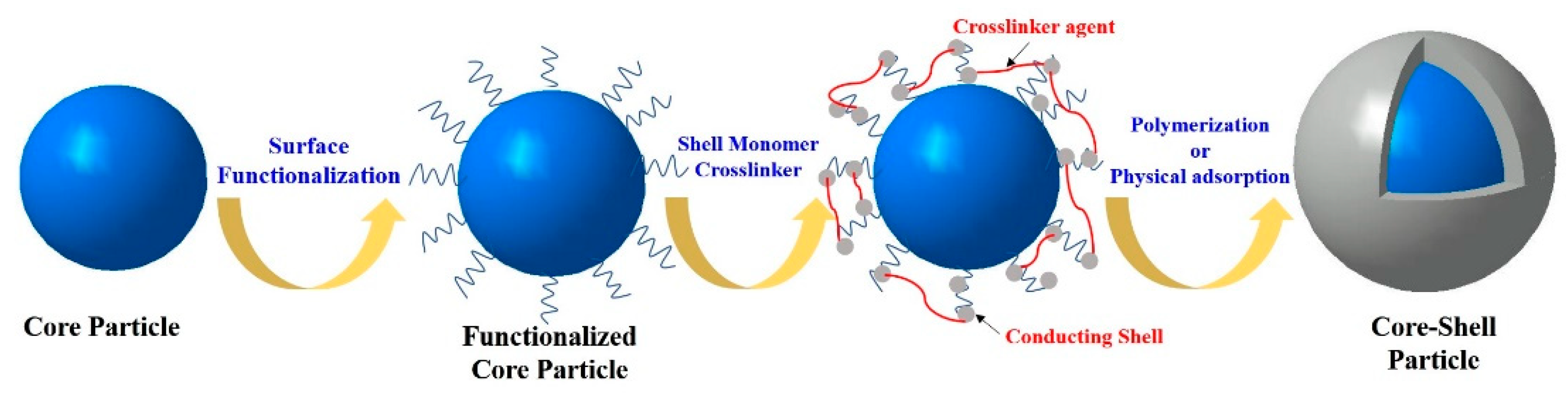
2. Fabrication and Morphologies
2.1. PANI and Its Derivatives
2.1.1. PANI
Polymeric Core
Inorganic Core
2.1.2. Polyaniline Derivatives
2.2. Other Conducting Polymers
3. Thermal Properties
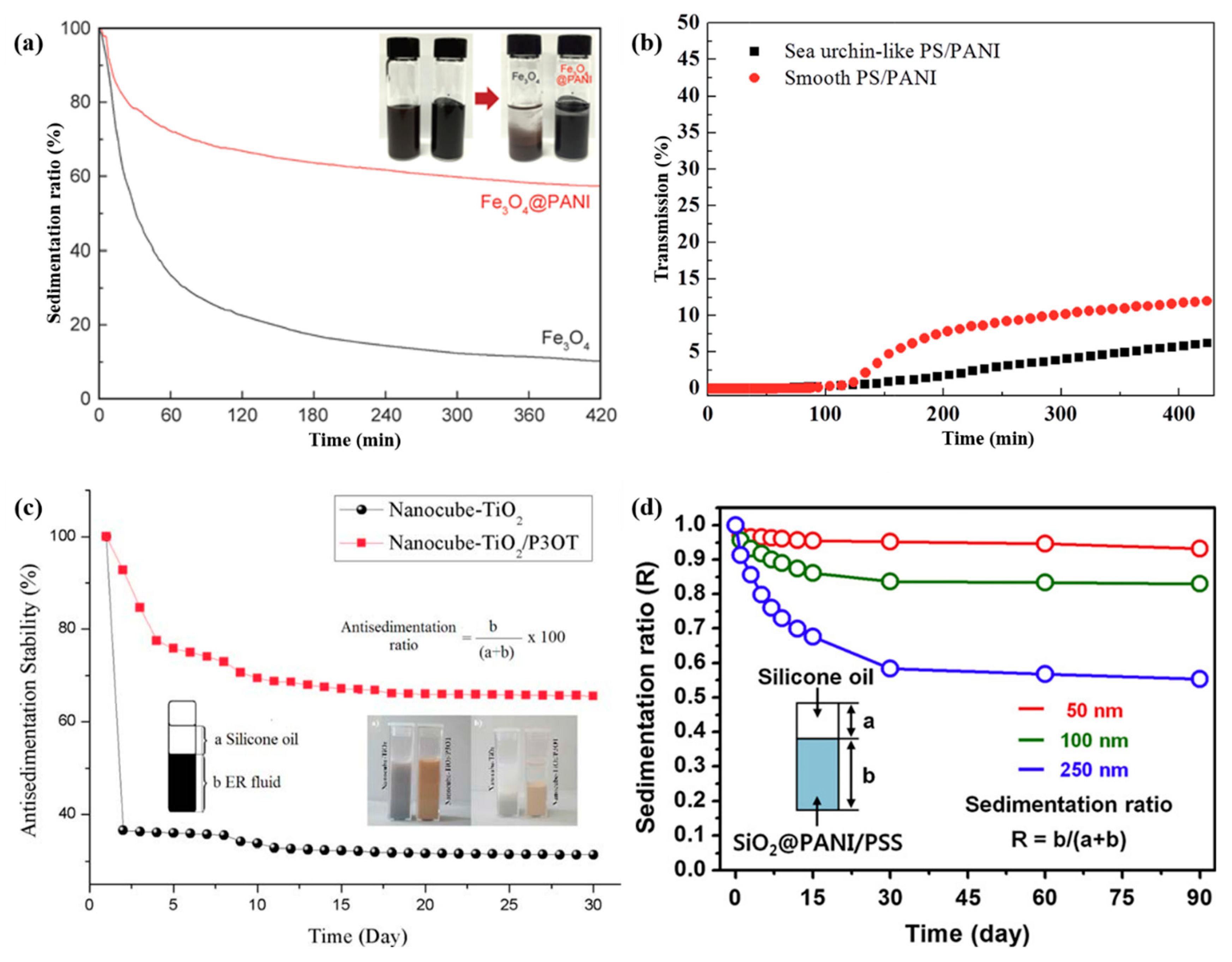
4. Sedimentation Stability
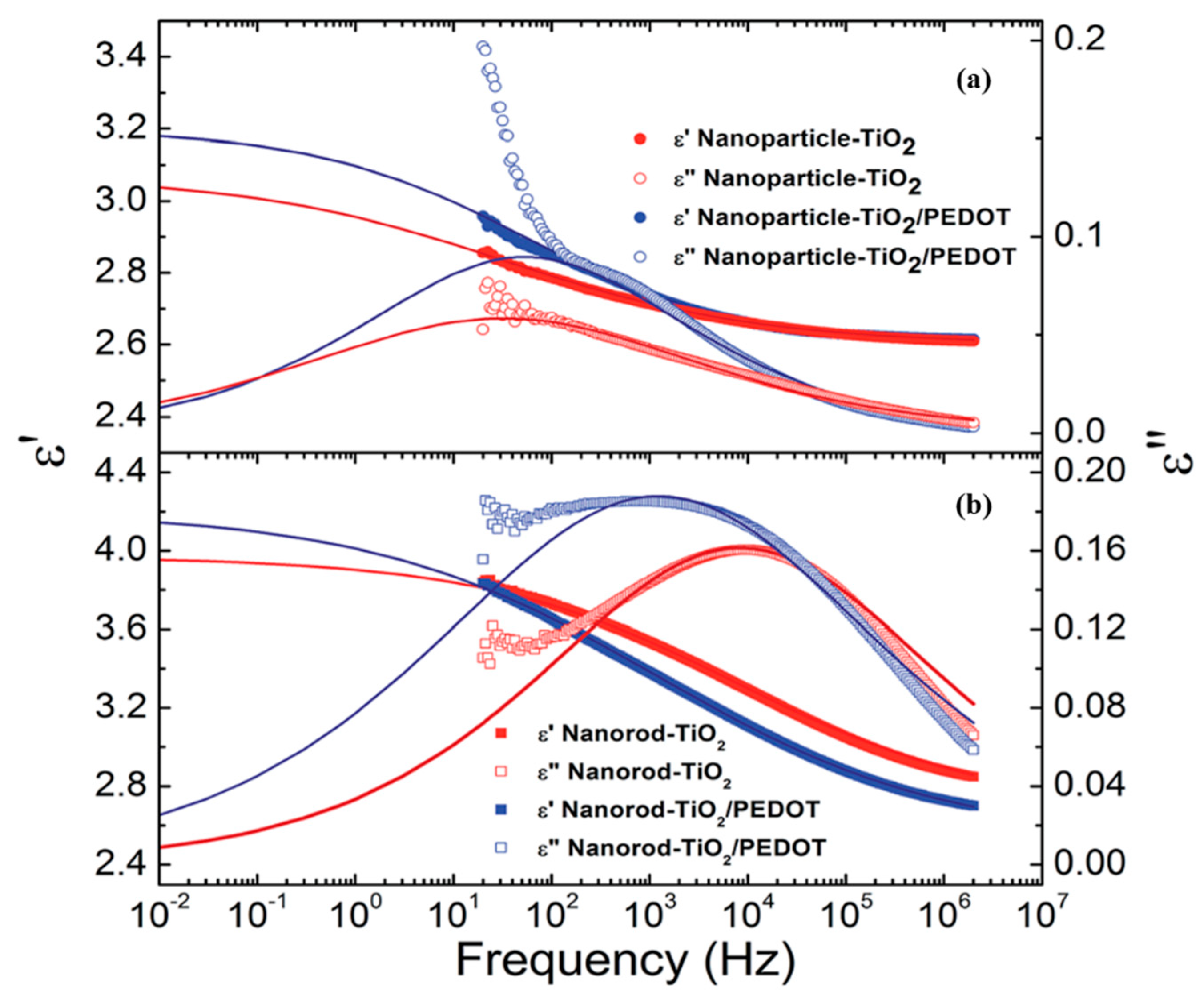
5. Dielectric Properties
6. Electrorheological Characteristics
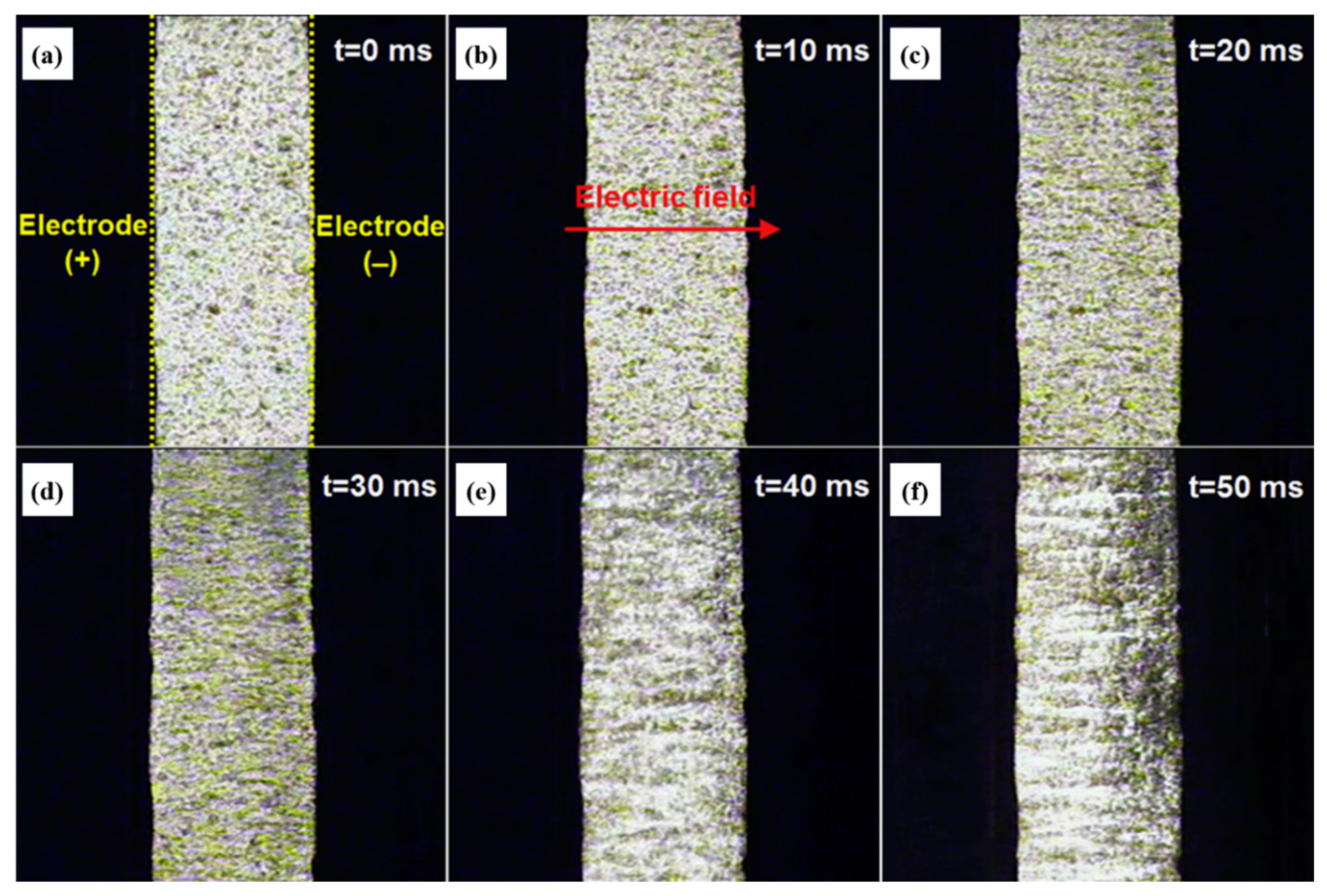
6.1. Electrorheological Phenomenon
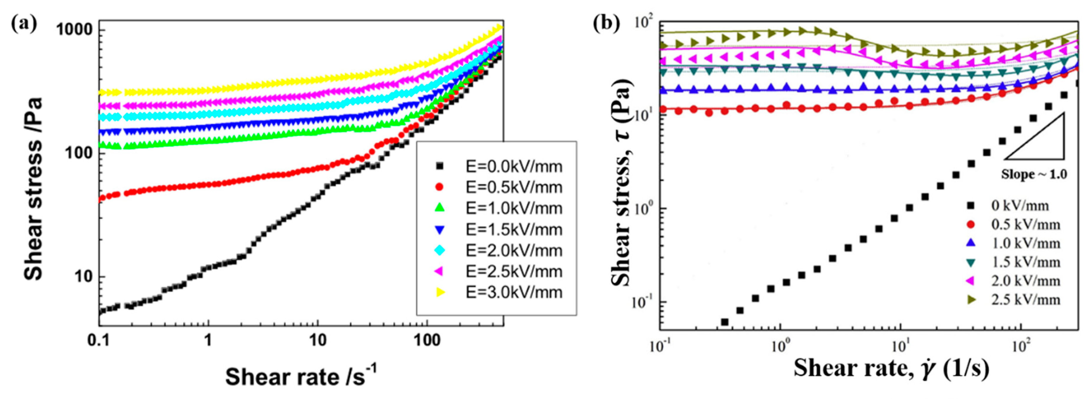
6.2. Steady Shear Tests
6.3. Dynamic Oscillation Tests
7. Magnetorheological Characteristics
7.1. Magnetic Particles
7.2. Magnetic Properties
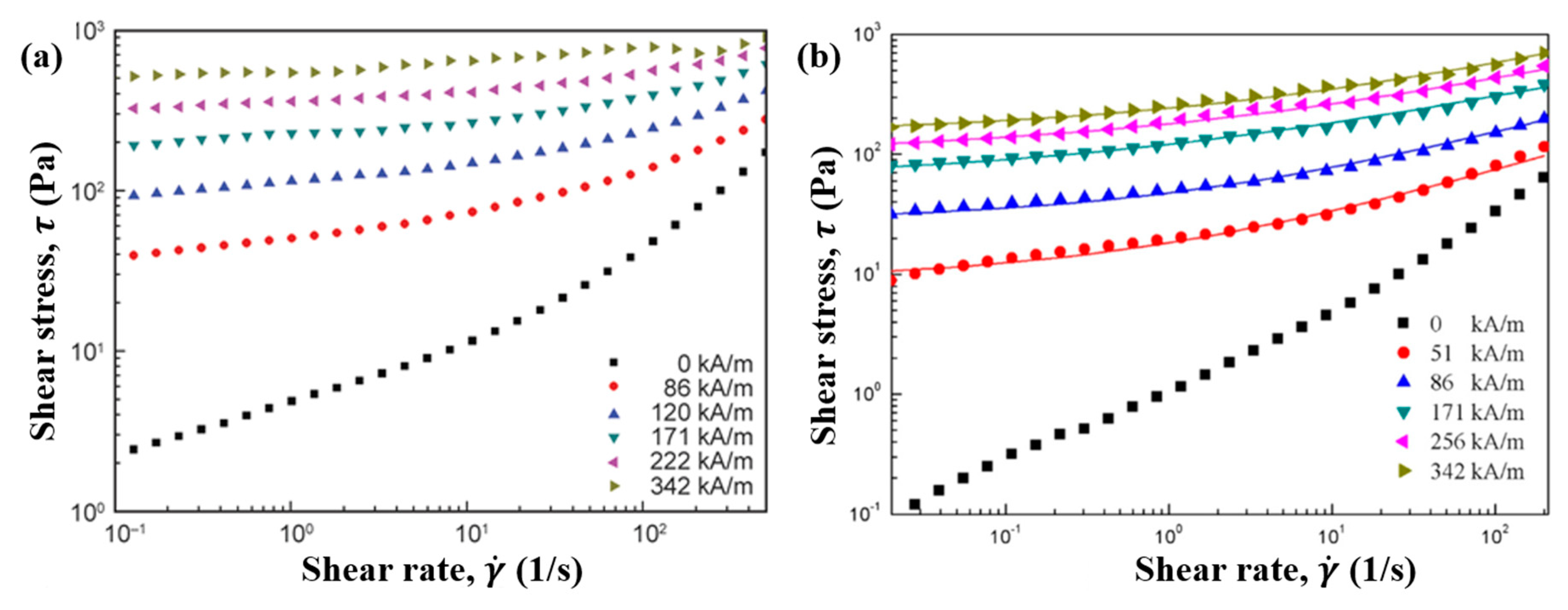
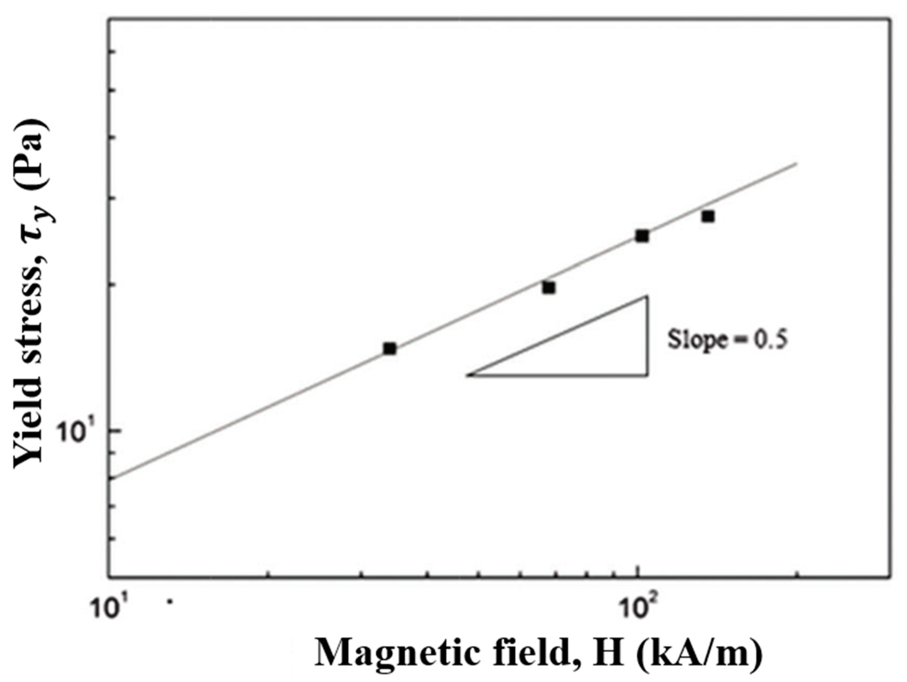
7.3. Steady Shear Tests
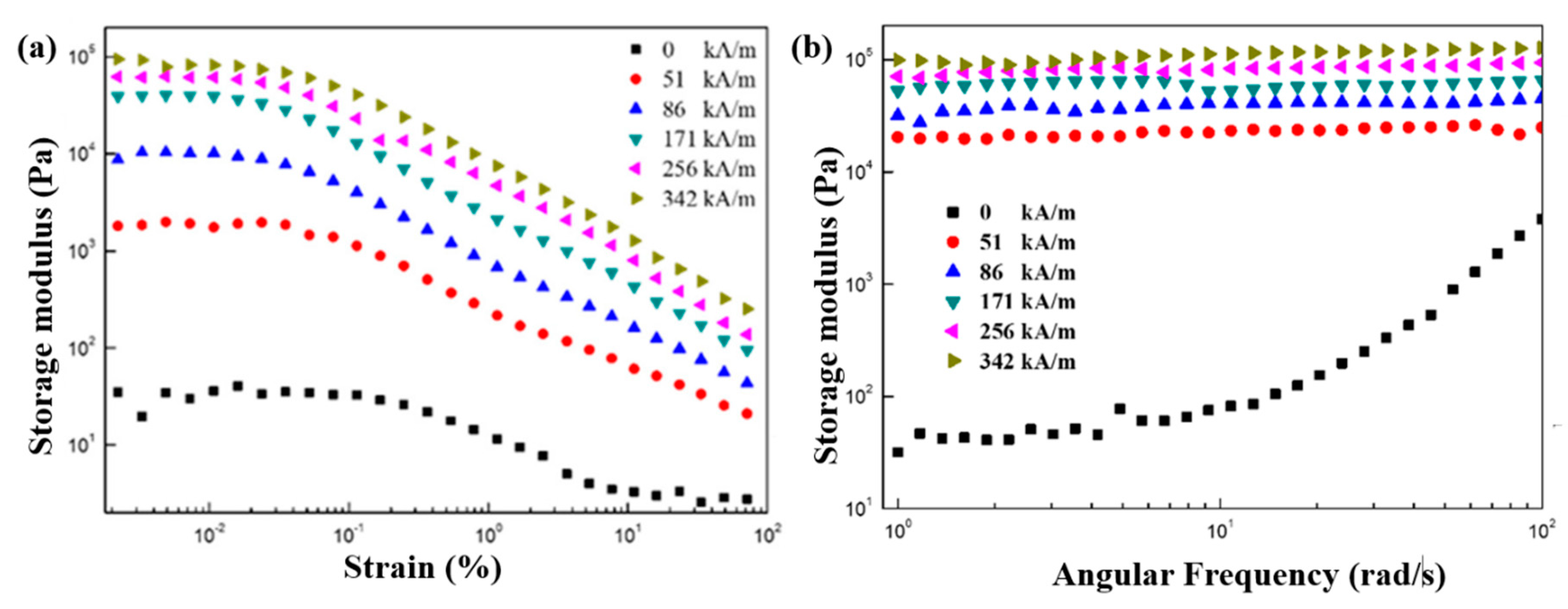
7.4. Dynamic Oscillation Tests
8. Conclusions
Author Contributions
Funding
Conflicts of Interest
References
- Gamerith, C.; Luschnig, D.; Ortner, A.; Pietrzik, N.; Guse, J.-H.; Burnet, M.; Haalboom, M.; van der Palen, J.; Heinzle, A.; Sigl, E.; et al. pH-responsive materials for optical monitoring of wound status. Sens. Actuators B Chem. 2019, 301, 126966. [Google Scholar] [CrossRef]
- Abdollahi, A.; Roghani-Mamaqani, H.; Razavi, B.; Salami-Kalajahi, M. The light-controlling of temperature-responsivity in stimuli-responsive polymers. Polym. Chem. 2019, 10, 5686–5720. [Google Scholar] [CrossRef]
- Li, M.; Zhang, H.; Gao, F.; Tang, Z.; Zeng, D.; Pan, Y.; Su, P.; Ruan, Y.; Xu, Y.; Weng, W. A cyclic cinnamate dimer mechanophore for multimodal stress responsive and mechanically adaptable polymeric materials. Polym. Chem. 2019, 10, 905–910. [Google Scholar] [CrossRef]
- Martin, J.E.; Odinek, J.; Halsey, T.C.; Kamien, R. Structure and dynamics of electrorheological fluids. Phys. Rev. E 1998, 57, 756–775. [Google Scholar] [CrossRef]
- Choi, H.J.; Jhon, M.S. Electrorheology of polymers and nanocomposites. Soft Matter 2009, 5, 1562–1567. [Google Scholar] [CrossRef]
- Yin, J.; Zhao, X. Electrorheology of nanofiber suspensions. Nanoscale Res. Lett. 2011, 6, 256. [Google Scholar] [CrossRef]
- Sheng, P.; Wen, W. Electrorheology: Statics and dynamics. Solid State Commun. 2010, 150, 1023–1039. [Google Scholar] [CrossRef]
- Yamaguchi, H.; Zhang, X.-R.; Niu, X.-D.; Nishioka, K. Investigation of impulse response of an ER fluid viscous damper. J. Intell. Mater. Syst. Struct. 2010, 21, 423–435. [Google Scholar] [CrossRef]
- Lee, I.S.; Lee, J.Y.; Sung, J.H.; Choi, H.J. Synthesis and electrorheological characteristics of polyaniline-titanium dioxide hybrid suspension. Synth. Met. 2005, 152, 173–176. [Google Scholar] [CrossRef]
- Kim, Y.D.; Song, I.C. Electrorheological and dielectric properties of polypyrrole dispersions. J. Mater. Sci. 2002, 37, 5051–5055. [Google Scholar] [CrossRef]
- Seo, Y.P.; Seo, Y. Modeling and analysis of electrorheological suspensions in shear flow. Langmuir 2012, 28, 3077–3084. [Google Scholar] [CrossRef] [PubMed]
- Ashour, O.; Rogers, C.A.; Kordonsky, W. Magnetorheological fluids: Materials, characterization, and devices. J. Intell. Mater. Syst. Struct. 1996, 7, 123–130. [Google Scholar] [CrossRef]
- Wang, G.; Zhao, D.; Li, N.; Zeng, Y.; Han, S.; Ma, Y.; Dong, X.; Yu, R. Facile synthesis of hierarchically structured flower-like Fe3O4 microspheres for high-performance magnetorheological fluids. J. Ind. Eng. Chem. 2019, 79, 217–225. [Google Scholar] [CrossRef]
- Bilyk, V.A.; Korobko, E.V. Research of the influence of dissipative heating on the performance characteristics of electrorheological shock absorbers. J. Intell. Mater. Syst. Struct. 2015, 26, 1906–1912. [Google Scholar] [CrossRef]
- Liu, Y.; Davidson, R.; Taylor, P. Touch sensitive electrorheological fluid based tactile display. Smart Mater. Struct. 2005, 14, 1563–1568. [Google Scholar] [CrossRef]
- Niu, X.; Liu, L.; Wen, W.; Sheng, P. Microfluidic manipulation in lab-chips using electrorheological fluid. J. Intell. Mater. Syst. Struct. 2007, 18, 1187–1190. [Google Scholar] [CrossRef]
- Nanthakumar, A.J.D.; Jancirani, J. Design optimization of magnetorheological damper geometry using response surface method for achieving maximum yield stress. J. Mech. Sci. Technol. 2019, 33, 4319–4329. [Google Scholar] [CrossRef]
- Keshav, M.; Chandramohan, S. Geometric optimisation of magnetorheological valve using feedforward neural networks for distribution of magnetic flux density inside the valve. Smart Mater. Struct. 2019, 28, 105018. [Google Scholar] [CrossRef]
- Hwang, Y.-H.; Kang, S.-R.; Cha, S.-W.; Choi, S.-B. A robot-assisted cutting surgery of human-like tissues using a haptic master operated by magnetorheological clutches and brakes. Smart Mater. Struct. 2019, 28, 065016. [Google Scholar] [CrossRef]
- Huo, L.; Liao, F.-H.; Li, J.-R. Synthesis and electrorheological performance of nanosized composite with polar inorganic compounds. Compos. Sci. Technol. 2011, 71, 1639–1643. [Google Scholar] [CrossRef]
- Plachy, T.; Sedlacik, M.; Pavlínek, V.; Stejskal, J. The observation of a conductivity threshold on the electrorheological effect of p-phenylenediamine oxidized with p-benzoquinone. J. Mater. Chem. C 2015, 3, 9973–9980. [Google Scholar] [CrossRef]
- Stejskal, J.; Mrlík, M.; Plachý, T.; Trchová, M.; Kovářová, J.; Li, Y. Molybdenum and tungsten disulfides surface-modified with a conducting polymer, polyaniline, for application in electrorheology. React. Funct. Polym. 2017, 120, 30–37. [Google Scholar] [CrossRef]
- Kim, D.-H.; Kim, Y.D. Electrorheological properties of polypyrrole and its composite ER fluids. J. Ind. Eng. Chem. 2007, 13, 879–894. [Google Scholar]
- Hong, J.-Y.; Kwon, E.; Jang, J. Fabrication of silica/polythiophene core/shell nanospheres and their electrorheological fluid application. Soft Matter 2009, 5, 951–953. [Google Scholar] [CrossRef]
- Sim, I.S.; Kim, J.W.; Choi, H.J.; Kim, C.A.; Jhon, M.S. Preparation and electrorheological characteristics of poly (p-phenylene)-based suspensions. Chem. Mater. 2001, 13, 1243–1247. [Google Scholar] [CrossRef]
- Quadrat, O.; Stejskal, J. Polyaniline in electrorheology. J. Ind. Eng. Chem. 2006, 12, 352–361. [Google Scholar]
- Gercek, B.; Yavuz, M.; Yilmaz, H.; Sari, B.; Unal, H.I. Comparison of electrorheological properties of some polyaniline derivatives. Colloids Surf. A 2007, 299, 124–132. [Google Scholar] [CrossRef]
- Kim, S.H.; Choi, H.J.; Leong, Y.-K. Flow curve analysis of a Pickering emulsion polymerized PEDOT:PSS/PS-based electrorheological fluid. Smart Mater. Struct. 2017, 26, 117001. [Google Scholar] [CrossRef]
- Oh, S.Y.; Kang, T.J. Electrorheological response of inorganic-coated multi-wall carbon nanotubes with core–shell nanostructure. Soft Matter 2014, 10, 3726–3737. [Google Scholar] [CrossRef]
- Wang, B.; Zhao, X. Core/shell nanocomposite based on the local polarization and its electrorheological behavior. Langmuir 2005, 21, 6553–6559. [Google Scholar] [CrossRef]
- Pavlínek, V.; Sáha, P.; Kitano, T.; Stejskal, J.; Quadrat, O. The effect of polyaniline layer deposited on silica particles on electrorheological and dielectric properties of their silicone–oil suspensions. Physica A 2005, 353, 21–28. [Google Scholar] [CrossRef]
- Ji, X.; Zhang, W.; Jia, W.; Wang, X.; Tian, Y.; Deng, L.; Liu, J. Cactus-like double-shell structured SiO2@ TiO2 microspheres: Fabrication, electrorheological performances and microwave absorption. J. Ind. Eng. Chem. 2017, 56, 203–211. [Google Scholar] [CrossRef]
- Choi, H.J.; Zhang, W.L.; Kim, S.; Seo, Y. Core-shell structured electro-and magneto-responsive materials: Fabrication and characteristics. Materials 2014, 7, 7460–7471. [Google Scholar] [CrossRef] [PubMed]
- Bellucci, S.; Bolesta, I.; Guidi, M.C.; Karbovnyk, I.; Lesivciv, V.; Micciulla, F.; Pastore, R.; Popov, A.; Velgosh, S. Cadmium clusters in CdI2 layered crystals: The influence on the optical properties. J. Phys. Condens. Matter 2007, 19, 395015. [Google Scholar] [CrossRef]
- Cao, L.; Park, H.; Dodbiba, G.; Fujita, T. Dispersion of submicron Ni particles into liquid gallium. Magnetohydrodynamics 2008, 44, 97–104. [Google Scholar] [CrossRef]
- Lee, J.Y.; Kwon, S.H.; Choi, H.J. Magnetorheological characteristics of carbonyl iron microparticles with different shapes. Korea Aust. Rheol. J. 2019, 31, 41–47. [Google Scholar] [CrossRef]
- Seo, Y.P.; Kwak, S.; Choi, H.J.; Seo, Y. Static yield stress of a magnetorheological fluid containing Pickering emulsion polymerized Fe2O3/polystyrene composite particles. J. Colloid Interface Sci. 2016, 463, 272–278. [Google Scholar] [CrossRef]
- Abe, H.; Naka, T.; Sato, K.; Suzuki, Y.; Nakano, M. Shape-controlled syntheses of magnetite microparticles and their magnetorheology. Int. J. Mol. Sci. 2019, 20, 3617. [Google Scholar] [CrossRef]
- Jiang, W.; Cao, Z.; Gu, R.; Ye, X.; Jiang, C.; Gong, X. A simple route to synthesize ZnFe2O4 hollow spheres and their magnetorheological characteristics. Smart Mater. Struct. 2009, 18, 125013. [Google Scholar] [CrossRef]
- Kim, M.W.; Han, W.J.; Kim, Y.H.; Choi, H.J. Effect of a hard magnetic particle additive on rheological characteristics of microspherical carbonyl iron-based magnetorheological fluid. Colloids Surf. A 2016, 506, 812–820. [Google Scholar] [CrossRef]
- Dong, Y.Z.; Choi, H.J. Synthesis of organic–inorganic poly (diphenylamine)/magnetite composite particles and their magnetorheological response. IEEE Trans. Magn. 2018, 54, 1–4. [Google Scholar] [CrossRef]
- Abshinova, M.A.; Kazantseva, N.E.; Sáha, P.; Sapurina, I.; Kovářová, J.; Stejskal, J. The enhancement of the oxidation resistance of carbonyl iron by polyaniline coating and consequent changes in electromagnetic properties. Polym. Degrad. Stab. 2008, 93, 1826–1831. [Google Scholar] [CrossRef]
- Cvek, M.; Mrlík, M.; Ilčíková, M.; Mosnáček, J.; Babayan, V.; Kuceková, Z.; Humpolíček, P.; Pavlínek, V. The chemical stability and cytotoxicity of carbonyl iron particles grafted with poly(glycidyl methacrylate) and the magnetorheological activity of their suspensions. RSC Adv. 2015, 5, 72816–72824. [Google Scholar] [CrossRef]
- Liu, Y.D.; Zhang, K.; Zhang, W.L.; Choi, H.J. Conducting material-incorporated electrorheological fluids: Core-shell structured spheres. Aust. J. Chem. 2012, 65, 1195–1202. [Google Scholar] [CrossRef]
- Cho, Y.H.; Cho, M.S.; Choi, H.J.; Jhon, M.S. Electrorheological characterization of polyaniline-coated poly (methyl methacrylate) suspensions. Colloid Polym. Sci. 2002, 280, 1062–1066. [Google Scholar]
- Li, Y.; Wang, Z.; Wang, C.; Zhao, Z.; Xue, G. Controlling the morphology of micrometre-size polystyrene/polyaniline composite particles by swelling-diffusion-interfacial-polymerization method. Polymer 2011, 52, 409–414. [Google Scholar] [CrossRef]
- Trlica, J.; Sáha, P.; Quadrat, O.; Stejskal, J. Electrorheology of polyaniline-coated silica particles in silicone oil. J. Phys. D Appl. Phys. 2000, 33, 1773–1780. [Google Scholar] [CrossRef]
- Fang, Q.; Zhang, J.; Bai, L.; Duan, J.; Xu, H.; Cham-Fai Leung, K.; Xuan, S. In situ redox-oxidation polymerization for magnetic core-shell nanostructure with polydopamine-encapsulated-Au hybrid shell. J. Hazard. Mater. 2019, 367, 15–25. [Google Scholar] [CrossRef]
- Xuan, S.; Wang, Y.-X.J.; Yu, J.C.; Leung, K.C.-F. Preparation, Characterization, and catalytic activity of core/shell Fe3O4@polyaniline@Au nanocomposites. Langmuir 2009, 25, 11835–11843. [Google Scholar] [CrossRef]
- Zhang, J.; Fang, Q.; Duan, J.; Xu, H.; Xu, H.; Xuan, S. Magnetically separable nanocatalyst with the Fe3O4 core and polydopamine-sandwiched Au nanocrystal Shell. Langmuir 2018, 34, 4298–4306. [Google Scholar] [CrossRef]
- Park, I.H.; Choi, H.J. Fabrication of p-aminobenzoic acid grafted carbonyl iron/polyindole composite particles and their magnetorheological response. J. Ind. Eng. Chem. 2018, 64, 102–106. [Google Scholar] [CrossRef]
- Min, T.H.; Choi, H.J.; Kim, N.-H.; Park, K.; You, C.-Y. Effects of surface treatment on magnetic carbonyl iron/polyaniline microspheres and their magnetorheological study. Colloids Surf. A 2017, 531, 48–55. [Google Scholar] [CrossRef]
- Yang, G.; Takei, T.; Yanagida, S.; Kumada, N. Hexagonal tungsten oxide-polyaniline hybrid electrodes for high-performance energy storage. Appl. Surf. Sci. 2019, 498, 143872. [Google Scholar] [CrossRef]
- Yang, Y.-F.; Meng, F.-Y.; Li, X.-H.; Wu, N.-N.; Deng, Y.-H.; Wei, L.-Y.; Zeng, X.-P. Magnetic Graphene Oxide-Fe3O4-PANI Nanoparticle Adsorbed Platinum Drugs as Drug Delivery Systems for Cancer Therapy. J. Nanosci. Nanotechnol. 2019, 19, 7517–7525. [Google Scholar] [CrossRef]
- Faisal, M.; Harraz, F.A.; Ismail, A.A.; Alsaiari, M.A.; Al-Sayari, S.A.; Al-Assiri, M.S. Novel synthesis of Polyaniline/SrSnO3 nanocomposites with enhanced photocatalytic activity. Ceram. Int. 2019, 45, 20484–20492. [Google Scholar] [CrossRef]
- Fang, F.F.; Dong, Y.-Z.; Choi, H.J. Effect of oxidants on morphology of interfacial polymerized polyaniline nanofibers and their electrorheological response. Polymer 2018, 158, 176–182. [Google Scholar] [CrossRef]
- Sim, B.; Choi, H.J. Facile synthesis of polyaniline nanotubes and their enhanced stimuli-response under electric fields. RSC Adv. 2015, 5, 11905–11912. [Google Scholar] [CrossRef]
- Dong, H.; Prasad, S.; Nyame, V.; Jones, W.E. Sub-micrometer conducting polyaniline tubes prepared from polymer fiber templates. Chem. Mater. 2004, 16, 371–373. [Google Scholar] [CrossRef]
- Otsubo, Y.; Sekine, M.; Katayama, S. Effect of surface modification of colloidal silica on the electrorheology of suspensions. J. Colloid Interface Sci. 1991, 146, 395–404. [Google Scholar] [CrossRef]
- Voorn, D.; Ming, W.; Van Herk, A. Clay platelets encapsulated inside latex particles. Macromolecules 2006, 39, 4654–4656. [Google Scholar] [CrossRef]
- Piao, S.H.; Gao, C.Y.; Choi, H.J. Sulfonated polystyrene nanoparticles coated with conducting polyaniline and their electro-responsive suspension characteristics under electric fields. Polymer 2017, 127, 174–181. [Google Scholar] [CrossRef]
- Hiamtup, P.; Sirivat, A.; Jamieson, A.M. Electrorheological properties of polyaniline suspensions: Field-induced liquid to solid transition and residual gel structure. J. Colloid Interface Sci. 2006, 295, 270–278. [Google Scholar] [CrossRef] [PubMed]
- Yin, J.; Xia, X.; Xiang, L.; Qiao, Y.; Zhao, X. The electrorheological effect of polyaniline nanofiber, nanoparticle and microparticle suspensions. Smart Mater. Struct. 2009, 18, 095007. [Google Scholar] [CrossRef]
- Marins, J.A.; Giulieri, F.; Soares, B.G.; Bossis, G. Hybrid polyaniline-coated sepiolite nanofibers for electrorheological fluid applications. Synth. Met. 2013, 185, 9–16. [Google Scholar] [CrossRef]
- Liu, Y.D.; Park, B.J.; Kim, Y.H.; Choi, H.J. Smart monodisperse polystyrene/polyaniline core–shell structured hybrid microspheres fabricated by a controlled releasing technique and their electro-responsive characteristics. J. Mater. Chem. 2011, 21, 17396–17402. [Google Scholar] [CrossRef]
- Kim, D.; Tian, Y.; Choi, H.J. Seeded swelling polymerized sea urchin-like core–shell typed polystyrene/polyaniline particles and their electric stimuli-response. RSC Adv. 2015, 5, 81546–81553. [Google Scholar] [CrossRef]
- Lee, I.S.; Cho, M.S.; Choi, H.J. Preparation of polyaniline coated poly(methyl methacrylate) microsphere by graft polymerization and its electrorheology. Polymer 2005, 46, 1317–1321. [Google Scholar] [CrossRef]
- Liu, Y.D.; Fang, F.F.; Choi, H.J. Core−shell structured semiconducting PMMA/polyaniline snowman-like anisotropic microparticles and their electrorheology. Langmuir 2010, 26, 12849–12854. [Google Scholar] [CrossRef]
- Park, D.E.; Choi, H.J.; Manh Vu, C. Stimuli-responsive polyaniline coated silica microspheres and their electrorheology. Smart Mater. Struct. 2016, 25, 055020. [Google Scholar] [CrossRef]
- Lee, S.; Hong, J.-Y.; Jang, J. Synthesis and electrical response of polyaniline/poly(styrene sulfonate)-coated silica spheres prepared by seed-coating method. J. Colloid Interface Sci. 2013, 398, 33–38. [Google Scholar] [CrossRef]
- Wang, B.; Liu, C.; Yin, Y.; Yu, S.; Chen, K.; Liu, P.; Liang, B. Double template assisting synthesized core–shell structured titania/polyaniline nanocomposite and its smart electrorheological response. Compos. Sci. Technol. 2013, 86, 89–100. [Google Scholar] [CrossRef]
- Sim, B.; Chae, H.S.; Choi, H.J. Fabrication of polyaniline coated iron oxide hybrid particles and their dual stimuli-response under electric and magnetic fields. Express Polym. Lett. 2015, 9, 736–743. [Google Scholar] [CrossRef]
- Tian, X.; He, K.; Wang, B.; Yu, S.; Hao, C.; Chen, K.; Lei, Q. Flower-like Fe2O3/polyaniline core/shell nanocomposite and its electroheological properties. Colloids Surf. A 2016, 498, 185–193. [Google Scholar] [CrossRef]
- Jang, D.S.; Choi, H.J. Conducting polyaniline-wrapped sepiolite composite and its stimuli-response under applied electric fields. Colloids Surf. A 2015, 469, 20–28. [Google Scholar] [CrossRef]
- Liu, Y.; Liu, P.; Su, Z. Core-shell attapulgite@polyaniline composite particles via in situ oxidative polymerization. Synth. Met. 2007, 157, 585–591. [Google Scholar] [CrossRef]
- Chae, H.S.; Zhang, W.L.; Piao, S.H.; Choi, H.J. Synthesized palygorskite/polyaniline nanocomposite particles by oxidative polymerization and their electrorheology. Appl. Clay Sci. 2015, 107, 165–172. [Google Scholar] [CrossRef]
- Moon, I.J.; Kim, H.Y.; Choi, H.J. Conducting poly(N-methylaniline)-coated cross-linked poly(methyl methacrylate) nanoparticle suspension and its steady shear response under electric fields. Colloids Surf. A 2015, 481, 506–513. [Google Scholar] [CrossRef]
- Kim, H.Y.; Choi, H.J. Core–shell structured poly (2-ethylaniline) coated crosslinked poly (methyl methacrylate) nanoparticles by graft polymerization and their electrorheology. RSC Adv. 2014, 4, 28511–28518. [Google Scholar] [CrossRef]
- Kwon, S.H.; Liu, Y.D.; Choi, H.J. Monodisperse poly (2-methylaniline) coated polystyrene core–shell microspheres fabricated by controlled releasing process and their electrorheological stimuli-response under electric fields. J. Colloid Interface Sci. 2015, 440, 9–15. [Google Scholar] [CrossRef]
- Lee, C.J.; Choi, H.J. Fabrication of poly(o-anisidine) coated silica core–shell microspheres and their electrorheological response. Mater. Res. Express 2017, 4, 116310. [Google Scholar] [CrossRef]
- Lee, H.J.; Lu, Q.; Lee, Y.J.; Choi, J.H. Polymer-Magnetic Composite Particles of Fe3O4/Poly(o-anisidine) and Their Suspension Characteristics under Applied Magnetic Fields. Polymers 2019, 11, 219. [Google Scholar] [CrossRef] [PubMed]
- Krztoń-Maziopa, A.; Wyciślik, H.; Płocharski, J. Study of electrorheological properties of poly(p-phenylene) dispersions. J. Rheol. 2005, 49, 1177–1192. [Google Scholar] [CrossRef]
- Wei, C.; Zhu, Y.; Jin, Y.; Yang, X.; Li, C. Fabrication and characterization of mesoporous TiO2/polypyrrole-based nanocomposite for electrorheological fluid. Mater. Res. Bull. 2008, 43, 3263–3269. [Google Scholar] [CrossRef]
- Chotpattananont, D.; Sirivat, A.; Jamieson, A.M. Electrorheological properties of perchloric acid-doped polythiophene suspensions. Colloid Polym. Sci. 2004, 282, 357–365. [Google Scholar] [CrossRef]
- Cabuk, M.; Yavuz, M.; Unal, H.I. Electrokinetic, electrorheological and viscoelastic properties of Polythiophene-graft-Chitosan copolymer particles. Colloids Surf. A 2016, 510, 231–238. [Google Scholar] [CrossRef]
- Corradi, R.; Armes, S. Chemical synthesis of poly (3,4-ethylenedioxythiophene). Synth. Met. 1997, 84, 453–454. [Google Scholar] [CrossRef]
- An, J.S.; Moon, I.J.; Kwon, S.H.; Choi, H.J. Swelling-diffusion-interfacial polymerized core-shell typed polystyrene/poly(3,4-ethylenedioxythiophene) microspheres and their electro-responsive characteristics. Polymer 2017, 115, 137–145. [Google Scholar] [CrossRef]
- Erol, O.; Unal, H. Core/shell-structured, covalently bonded TiO2/poly(3,4-ethylenedioxythiophene) dispersions and their electrorheological response: The effect of anisotropy. RSC Adv. 2015, 5, 103159–103171. [Google Scholar] [CrossRef]
- Park, D.E.; Dong, Y.Z.; Choi, H.J. Fabrication and electric stimuli-response of semiconducting poly(3,4-ethylenedioxythiophene)/silica nanocomposite particles. Eur. Polym. J. 2018, 101, 255–261. [Google Scholar] [CrossRef]
- Sever, E.; Unal, H.I. Colloidal properties of surface functionalized nanocube-TiO2/poly (3-octylthiophene) core/shell conducting nanocomposite. Appl. Surf. Sci. 2015, 355, 1028–1036. [Google Scholar] [CrossRef]
- Groenendaal, L.; Jonas, F.; Freitag, D.; Pielartzik, H.; Reynolds, J.R. Poly (3,4-ethylenedioxythiophene) and its derivatives: Past, present, and future. Adv. Mater. 2000, 12, 481–494. [Google Scholar] [CrossRef]
- Liu, Y.D.; Kim, J.E.; Choi, H.J. Core-shell structured monodisperse poly(3,4-Ethylenedioxythiophene)/poly(styrenesulfonic acid) coated polystyrene microspheres and their electrorheological response. Macromol. Rapid Commun. 2011, 32, 881–886. [Google Scholar] [CrossRef] [PubMed]
- Kim, S.H.; Kim, J.H.; Choi, H.J.; Park, J. Pickering emulsion polymerized poly (3,4-ethylenedioxythiophene): Poly (styrenesulfonate)/polystyrene composite particles and their electric stimuli-response. RSC Adv. 2015, 5, 72387–72393. [Google Scholar] [CrossRef]
- Sever, E.; Unal, H.I. Electrorheological, viscoelastic, and creep-recovery behaviors of covalently bonded nanocube-TiO2/Poly (3-octylthiophene) colloidal dispersions. Polym. Compos. 2018, 39, 351–359. [Google Scholar] [CrossRef]
- Kim, M.W.; Moon, I.J.; Choi, H.J.; Seo, Y. Facile fabrication of core/shell structured SiO2/polypyrrole nanoparticles with surface modification and their electrorheology. RSC Adv. 2016, 6, 56495–56502. [Google Scholar] [CrossRef]
- Hong, J.-Y.; Jang, J. A comparative study on electrorheological properties of various silica–conducting polymer core–shell nanospheres. Soft Matter 2010, 6, 4669–4671. [Google Scholar] [CrossRef]
- Park, D.E.; Chae, H.S.; Choi, H.J.; Maity, A. Magnetite–polypyrrole core–shell structured microspheres and their dual stimuli-response under electric and magnetic fields. J. Mater. Chem. C 2015, 3, 3150–3158. [Google Scholar] [CrossRef]
- Kim, M.H.; Choi, H.J. Core–shell structured semiconducting poly (diphenylamine)-coated polystyrene microspheres and their electrorheology. Polymer 2017, 131, 120–131. [Google Scholar] [CrossRef]
- Kim, M.H.; Bae, D.H.; Choi, H.J.; Seo, Y. Synthesis of semiconducting poly (diphenylamine) particles and analysis of their electrorheological properties. Polymer 2017, 119, 40–49. [Google Scholar] [CrossRef]
- Dong, Y.Z.; Choi, H.J. Electrorheological characteristics of poly (diphenylamine)/magnetite composite-based suspension. Materials 2019, 12, 2911. [Google Scholar] [CrossRef]
- Fang, F.F.; Liu, Y.D.; Lee, I.S.; Choi, H.J. Well controlled core/shell type polymeric microspheres coated with conducting polyaniline: Fabrication and electrorheology. RSC Adv. 2011, 1, 1026–1032. [Google Scholar] [CrossRef]
- Zhang, W.L.; Piao, S.H.; Choi, H.J. Facile and fast synthesis of polyaniline-coated poly(glycidyl methacrylate) core–shell microspheres and their electro-responsive characteristics. J. Colloid Interface Sci. 2013, 402, 100–106. [Google Scholar] [CrossRef] [PubMed]
- Abdullah, M.F.; Hashim, A.M. Improved coverage of rGO film on Si inverted pyramidal microstructures for enhancing the photovoltaic of rGO/Si heterojunction solar cell. Mater. Sci. Semicond. Process. 2019, 96, 137–144. [Google Scholar] [CrossRef]
- Yin, J.; Xia, X.; Xiang, L.; Zhao, X. Conductivity and polarization of carbonaceous nanotubes derived from polyaniline nanotubes and their electrorheology when dispersed in silicone oil. Carbon 2010, 48, 2958–2967. [Google Scholar] [CrossRef]
- Cabuk, S.; Unal, H.I. Enhanced electrokinetic, dielectric and electrorheological properties of covalently bonded nanosphere-TiO2/polypyrrole nanocomposite. React. Funct. Polym. 2015, 95, 1–11. [Google Scholar] [CrossRef]
- Shearer, S.A.; Hudson, J.R. Fluid mechanics: stokes’ law and viscosity. Meas. Lab. 2008, 3, 1–7. [Google Scholar]
- Liu, Y.D.; Quan, X.; Hwang, B.; Kwon, Y.K.; Choi, H.J. Core–shell-structured monodisperse copolymer/silica particle suspension and its electrorheological response. Langmuir 2014, 30, 1729–1734. [Google Scholar] [CrossRef]
- Tang, X.; Wu, C.; Conrad, H. On the conductivity model for the electrorheological effect. J. Rheol. 1995, 39, 1059–1073. [Google Scholar] [CrossRef]
- Seo, Y. A new yield stress scaling function for electrorheological fluids. J. Non-Newton. Fluid Mech. 2011, 166, 241–243. [Google Scholar] [CrossRef]
- Cho, M.; Choi, H.; Jhon, M. Shear stress analysis of a semiconducting polymer based electrorheological fluid system. Polymer 2005, 46, 11484–11488. [Google Scholar] [CrossRef]
- Mallick, K.; Witcomb, M.J.; Dinsmore, A.; Scurrell, M.S. Polymerization of aniline by auric acid: Formation of gold decorated polyaniline nanoballs. Macromol. Rapid Commun. 2005, 26, 232–235. [Google Scholar] [CrossRef]
- Sim, B.; Bae, D.H.; Choi, H.J.; Choi, K.; Islam, M.S.; Kao, N. Fabrication and stimuli response of rice husk-based microcrystalline cellulose particle suspension under electric fields. Cellulose 2016, 23, 185–197. [Google Scholar] [CrossRef]
- Emri, I.; Von Bernstorff, B.; Cvelbar, R.; Nikonov, A. Re-examination of the approximate methods for interconversion between frequency-and time-dependent material functions. J. Non-Newton. Fluid Mech. 2005, 129, 75–84. [Google Scholar] [CrossRef]


| ER Fluids (1.25 vol %) | (s) | ||||
|---|---|---|---|---|---|
| Nanoparticle-TiO2 | 3.07 | 2.60 | 0.47 | 5 × 10⁻³ | 0.69 |
| Nanoparticle-TiO2/PEDOT | 3.20 | 2.60 | 0.60 | 3 × 10⁻³ | 0.63 |
| Nanorod-TiO2 | 3.97 | 2.67 | 1.30 | 1.9 × 10⁻⁵ | 0.69 |
| Nanorod-TiO2/PEDOT | 4.20 | 2.52 | 1.68 | 1.3 × 10⁻⁴ | 0.72 |
| Material | Synthesis | Morphology | Core | Shell | Concentration | Slope | Δε | λ (s) | |||||
|---|---|---|---|---|---|---|---|---|---|---|---|---|---|
| PS/PANI [61] | Electrostatic interaction (sulfuric acid treatment) | Spherical | 360 nm | 70 nm | 1.13 | 10−3 | 10−8 | 10 vol % | 2.5 | 420 | 2.0 | 1.24 | 3 × 10⁻⁵ |
| PS/PANI [66] | π-π stacking interaction | Sea urchin-like | 1.0 μm | 50 nm | 1.29 | 1.13 × 10⁻² | 2.24 × 10⁻¹¹ | 10 vol % | 3.0 | 102 | 1.5 | 2.27 | 5.7 × 10⁻³ |
| SiO2/PANI [69] | π-π stacking interaction (aniline group modification) | Spherical | ~1.0 μm | 50 nm | 1.87 | 1.8 × 10⁻² | 5.8 × 10⁻¹² | 20 vol % | 3.0 | 187 | 2.0 | 0.98 | 1.5 × 10⁻² |
| PANI/PSS-coated SiO2 [70] | Seed-coating method (amino modification) | Spherical | 50 nm | 2 nm | 2.57 | _ | _ | 5–30 vol % | 3.0 | ~7200 (30 vol %) | 2.0–1.5 | _ | _ |
| 100 nm | 2 nm | 2.62 | _ | _ | 5–30 vol % | 3.0 | ~5300 (30 vol %) | 2.0–1.5 | _ | _ | |||
| 250 nm | 2 nm | 2.64 | _ | _ | 5–30 vol % | 3.0 | ~3200 (30 vol %) | 2.0–1.5 | _ | _ | |||
| Fe3O4/PANI [72] | Electrostatic interaction (HCl modification) | Spherical | 0.7–1.0 μm | ~100 nm | 2.76 | _ | 5.56 × 10⁻⁸ | 20 wt % | 3.0 | 20 | 2.0 | _ | _ |
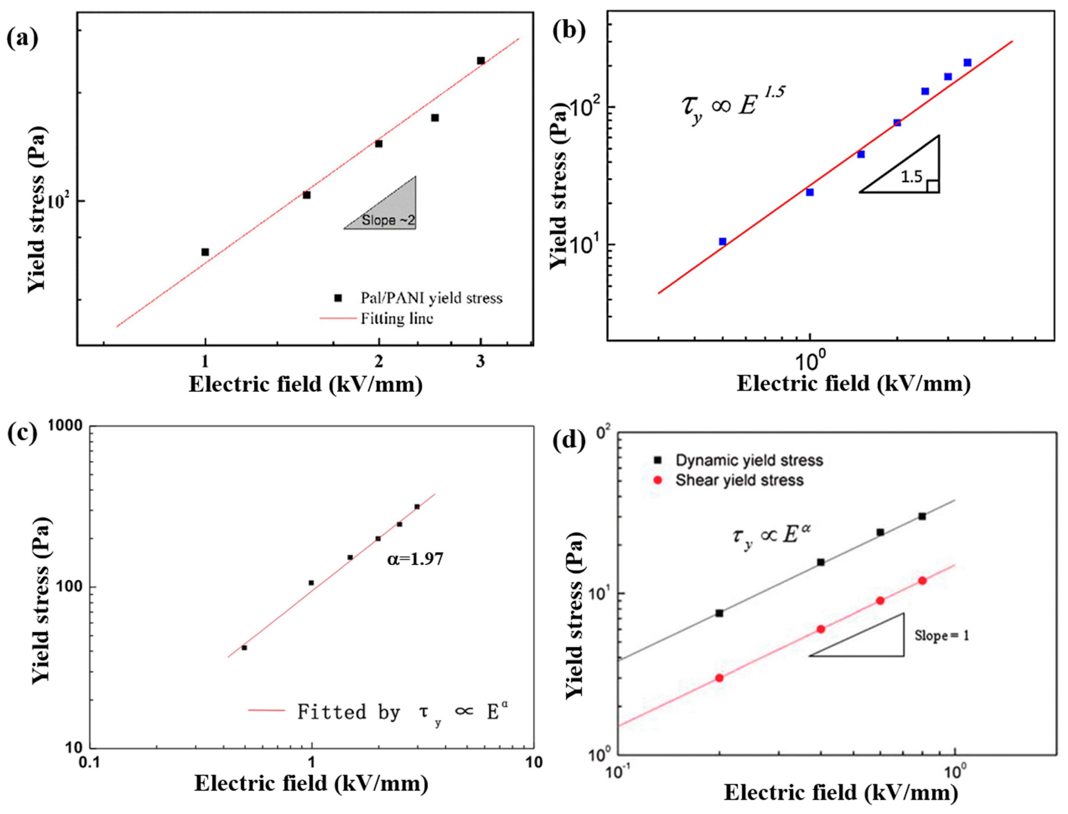
| Fe2O3/PANI [73] | Surfactant (CTAB) | Flower-like | _ | _ | _ | _ | De-doping | 20 wt % | 3.0 | ~300 | 1.97 | _ | _ |
| PANI/SPL [74] | Electrostatic interaction | Nano-needle | Length: 1–2.5 μm Diameter: 20-25 nm | _ | _ | _ | De-doping | 8 vol % | 1.6 | 242 | 1.5 | 2.12 | 1.65 × 10⁻⁴ |
| Pal/PANI [76] | Electrostatic interaction | Nano-fibrous | Length: ~μm Diameter: ~20 nm | _ | 1.77 | 10−3 | 10−8 | 10 vol % | 2.5 | 512 | 2.0 | 2.04 | 2.1 × 10⁻⁴ |
| PMMA-PNMA [77] | Chemical grafting (epoxy-amine reaction) | Spherical | 700 nm | 100 nm | _ | 9.319 × 10⁻⁴ | 5.35 × 10⁻¹⁰ | 10 vol % | 3.5 | 212 | 1.5 | _ | _ |
| PEAN-PMMA [78] | Chemical grafting (epoxy-amine reaction) | Spherical | 700 nm | 90 nm | _ | _ | without de-doping | 10 vol % | 3.5 | 458 | 2.0 | 0.89 | 9 × 10⁻⁷ |
| SiO2/POA [80] | π-π stacking interaction (aniline group modification) | Spherical | ~1.0 μm | 50 nm | _ | 3.6 × 10⁻⁷ | 7.2 × 10⁻¹⁰ | 10 vol % | 2.3 | ~100 | 1.5 | 3.9 | 1.7 × 10⁻³ |
| PS/PEDOT [87] | Swelling-diffusion-interfacial polymerization | Spherical | 1.05 μm | 10 nm | 10−4 | 10−8 | 10 vol % | 1.8 | 13.4 | 1.5 | _ | _ | |
| TiO2/PEDOT [88] | Covalent bonding (amino modification-thiophene grafting) | Nano-rod | Length: ~μm Diameter: 30–100 nm | 6–7 nm | 2.253 | 2.69 | 7.8 × 10⁻² | 1–5 vol % | 3.0 | 640 (5 vol %) | _ | 1.68 | 1.3 × 10⁻⁴ |
| Spherical | _ | _ | 2.558 | 2.63 | 6.8 × 10⁻² | 1–5 vol % | 3.0 | 15 (5 vol %) | _ | 0.6 | 3 × 10⁻³ | ||
| PEDOT/SiO2 [89] | In situ polymerization without surfactant | Spherical -like | ~300 nm | _ | 1.81 | 10−6 | 10−8 | 10 vol % | 2.5 | 200 | 2.0 | 0.38 | 4 × 10⁻⁶ |
| TiO2/P3OT [94] | Covalent bonding (amino modification-thiophene grafting) | Nano-cube | 300–700 nm | 12-30 nm | 3.37 | 1.16 × 10⁻⁵ | _ | 1.25–7.5 vol % | 3.5 | 360 (7.5 vol %) | _ | 0.092 | 2.7 × 10⁻⁴ |
| SiO2/PPy [95] | In situ polymerization (MPS modification) | Spherical | 500 nm | 90 nm | 1.98 | 2.3 × 10⁻⁸ | without de-doping | 10 vol % | 1.7 | 151 | 1.5 | 0.94 | 1.5 × 10⁻⁴ |
| SiO2/PT [24] | Seeded polymerization (Oxidation treatment by Fe3+) | Spherical | 7 nm | 2 nm | _ | 1.0 × 10⁻⁷ | without de-doping | 5–30 vol % | 3.0 | 3900 (30 vol %) | _ | _ | _ |
| 11 nm | 2 nm | _ | 1.0 × 10⁻⁷ | without de-doping | 5–30 vol % | 3.0 | ~2300 (30 vol %) | _ | _ | _ | |||
| 22 nm | 2 nm | _ | 1.0 × 10⁻⁷ | without de-doping | 5–30 vol % | 3.0 | ~1500 (30 vol %) | _ | _ | _ | |||
| SiO2/PT [96] | Electrostatic interaction (Oxidation treatment by Fe3+) | Spherical | 22 nm | 2 nm | _ | _ | _ | 30 vol % | 3.0 | ~1900 | _ | _ | _ |
| SiO2/PPy [96] | 22 nm | 2 nm | _ | _ | _ | 30 vol % | 3.0 | ~2800 | _ | _ | _ | ||
| SiO2/PEDOT [96] | 22 nm | 2 nm | _ | _ | _ | 30 vol % | 3.0 | ~3900 | _ | _ | _ | ||
| SiO2/PANI [96] | 22 nm | 2 nm | _ | _ | _ | 30 vol % | 3.0 | ~4400 | _ | _ | _ | ||
| Fe3O4/PPy [97] | In situ polymerization (sonication assisted) | Spherical | 456.6 nm | 60 nm | 2.24 | 10−2 | 10−7 | 10 vol % | 0.8 | ~30 | 1.0 | 2.49 | 5 × 10⁻³ |
| PS/PDPA [98] | π-π stacking interaction | Spherical | 1.05 μm | 16.12 nm | 1.127 | 10−11 | without de-doping | 5 vol % | 2.5 | 54.7 | 1.5 | 0.508 | 5.5 × 10⁻⁴ |
| Material | Synthesis | Morphology | Core | Shell | Ms | Concentration | Hmax (kA/m) | Slope | Enhanced Sedimentation Ratio | ||
|---|---|---|---|---|---|---|---|---|---|---|---|
| Fe3O4/PANI [72] | Electrostatic interactions (HCl modification) | spherical | 0.7–1.0 μm | ~100 nm | 2.76 | 38 | 20 wt % | 342 | 437 | 2.0 | ~45% |
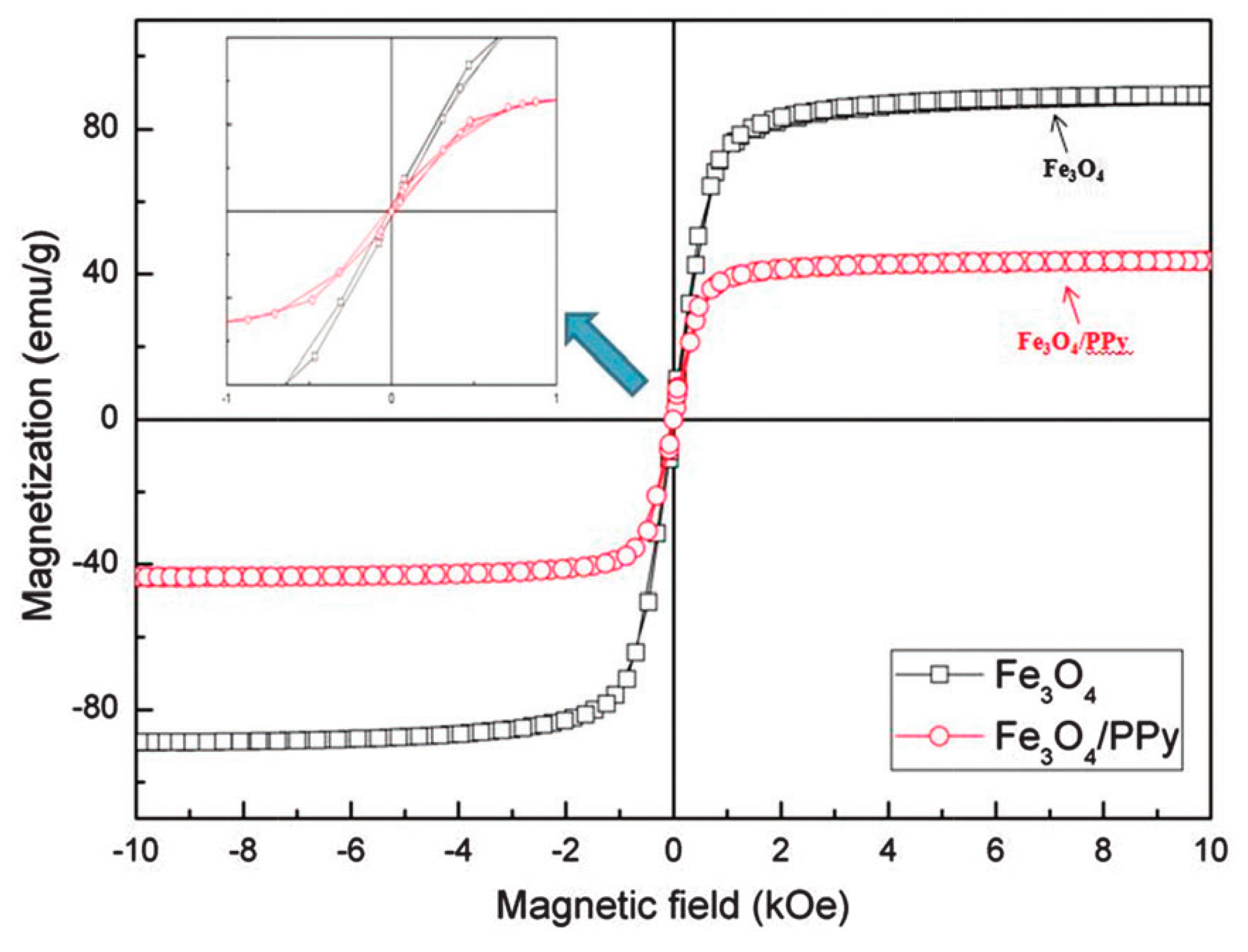
| Fe3O4/PPy [97] | In situ polymerization (sonication assisted) | spherical | 456.6 nm | 60 nm | 2.24 | 41 | 10 vol % | 136 | ~30 | 0.5 | _ |
| Fe3O4/POA [81] | Electrostatic interactions (HCl modification) | spherical | 445 nm | 60 nm | 2.52 | 36 | 10 vol % | 342 | ~200 | 1.5 | 50% |
© 2020 by the authors. Licensee MDPI, Basel, Switzerland. This article is an open access article distributed under the terms and conditions of the Creative Commons Attribution (CC BY) license (http://creativecommons.org/licenses/by/4.0/).
Share and Cite
Dong, Y.Z.; Choi, K.; Kwon, S.H.; Nam, J.-D.; Choi, H.J. Nanoparticles Functionalized by Conducting Polymers and Their Electrorheological and Magnetorheological Applications. Polymers 2020, 12, 204. https://doi.org/10.3390/polym12010204
Dong YZ, Choi K, Kwon SH, Nam J-D, Choi HJ. Nanoparticles Functionalized by Conducting Polymers and Their Electrorheological and Magnetorheological Applications. Polymers. 2020; 12(1):204. https://doi.org/10.3390/polym12010204
Chicago/Turabian StyleDong, Yu Zhen, Kisuk Choi, Seung Hyuk Kwon, Jae-Do Nam, and Hyoung Jin Choi. 2020. "Nanoparticles Functionalized by Conducting Polymers and Their Electrorheological and Magnetorheological Applications" Polymers 12, no. 1: 204. https://doi.org/10.3390/polym12010204
APA StyleDong, Y. Z., Choi, K., Kwon, S. H., Nam, J.-D., & Choi, H. J. (2020). Nanoparticles Functionalized by Conducting Polymers and Their Electrorheological and Magnetorheological Applications. Polymers, 12(1), 204. https://doi.org/10.3390/polym12010204