Review

A Review on Porous Polymeric Membrane Preparation. Part II: Production Techniques with Polyethylene, Polydimethylsiloxane, Polypropylene, Polyimide, and Polytetrafluoroethylene

1
College of Environment and Resources, Chongqing Technology and Business University, No.19, Xuefu Ave, Nan’an District, Chongqing 400067, China
2
Department of Chemical Engineering, Laval University, 1065 Avenue de la Médecine, Quebec, QC G1V 0A6, Canada
*
Authors to whom correspondence should be addressed.
Polymers 2019, 11(8), 1310; https://doi.org/10.3390/polym11081310
Submission received: 1 July 2019 / Revised: 30 July 2019 / Accepted: 31 July 2019 / Published: 5 August 2019
(This article belongs to the Collection Silicon-Containing Polymeric Materials)

Abstract

:
The development of porous polymeric membranes is an important area of application in separation technology. This article summarizes the development of porous polymers from the perspectives of materials and methods for membrane production. Polymers such as polyethylene, polydimethylsiloxane, polypropylene, polyimide, and polytetrafluoroethylene are reviewed due to their outstanding thermal stability, chemical resistance, mechanical strength, and low cost. Six different methods for membrane fabrication are critically reviewed, including thermally induced phase separation, melt-spinning and cold-stretching, phase separation micromolding, imprinting/soft molding, manual punching, and three-dimensional printing. Each method is described in details related to the strategy used to produce the porous polymeric membranes with a specific morphology and separation performances. The key factors associated with each method are presented, including solvent/non-solvent system type and composition, polymer solution composition and concentration, processing parameters, and ambient conditions. Current challenges are also described, leading to future development and innovation to improve these membranes in terms of materials, fabrication equipment, and possible modifications.

1. Introduction

In the field of membrane technology, a successful membrane is a barrier to selectively transport substances of interest. Since the core concept of an excellent membrane performance lies in its final morphology, the selection of materials and fabrication techniques have a significant effect on membrane morphology. Thus, the optimization of membrane performances must go through precise control of the interactions between morphology, materials, and fabrication technology [1,2,3].
With respect to materials, porous polymeric membranes have been widely applied for industrial processes due to a combination of specific properties such as permeability, selectivity, fouling resistance, chemical and thermal stability, low cost, and easy manufacturing. To date, the most popular membranes for separation processes include polyethylene (PE), polysulfone (PSU), poly (vinylidene fluoride) (PVDF), polydimethylsiloxane (PDMS), polypropylene (PP), polyimide (PI), and polytetrafluoroethylene (PTFE) membranes. For specific materials, the membrane morphology can be tailored by the precise control of the fabrication methods and processing conditions.
For their production, porous polymeric membranes can be made by several methods. Usual approaches include phase inversion, melt-spinning and cold-stretching (MSCS), electro-spinning, track etching, and sintering, while novel technologies include phase separation micromolding (PSµM), imprinting/soft molding, manual punching, and three-dimensional (3D) printing. Each method has its own advantages, limitations, and different pore formation mechanisms to produce porous polymeric membranes. Table 1 provides a comprehensive overview of the techniques used for membrane fabrication.
Over the past half century, significant knowledge has been generated regarding membrane technology. However, to the best of our knowledge, the majority of the literature focused on a specific preparation method or a given material. As a result, understanding the relationships between the membrane morphology and the fabrication parameters is very difficult. Thus, the main objective of this review paper is to summarize the existing and the potential principles to select appropriate methods and membrane fabrication systems to produce membranes with a desired morphology, performance, and stability, as well as to select the best method(s) to obtain these properties in an efficient way for future research. In the first part of this work, PSU and PVDF membranes produced by non-solvent induced phase separation (NIPS), vapor-induced phase separation (VIPS), electrospinning, track etching, and sintering [10]. In this second part, other methods for porous membrane fabrication are presented, and a focus on two other polymers is made: PE and PDMS. Nevertheless, polymers such as PP, PI, and PTFE are also introduced.
The main contribution of this article is to emphasize the methods and the processing conditions to achieve desired morphology, performance, and stability. The paper is organized as follows. Section 2 describes the membrane characterizations, including morphological and separation performances. Section 3 presents PE membranes, while Section 4 describes PDMS membranes. Section 5 presents an overview on PP, PI, and PTFE membranes. Each polymer is described in detail with respect to its key manufacturing parameters, providing the relationships between processing (methods and conditions) and morphology control. Finally, Section 6 presents some concluding remarks and insights for future studies.

2. Morphological and Performance Characterization of Membranes

2.1. Morphological Characterization

In general, the most important morphological parameters for a membrane are porosity, pore size, pore size distribution, tortuosity, surface roughness, molecular weight cutoff, and thickness. For example, the pore size plays a critical role in the membrane classification [40,41,42]: microfiltration (50–500 nm) [42,43], ultra-filtration (2–50 nm) [42,43], nano-filtration (≤2 nm) [42,43], reverse osmosis (0.3–0.6 nm) [42,44], and forward osmosis (0.3–0.6 nm) [42,44]. Furthermore, the membrane performances directly depend on its morphology (pore size and distribution), thus morphology control is the key factor in membrane fabrication.

2.2. Performance Characterization

Generally, the membrane performances can be evaluated by their productivity (rate) and separation ability (selectivity). Parameters such as flux (J), permeability (P), and permeance (P’) play essential roles in the evaluation of the membrane productivity, while efficiency (separation performance) is determined by the selectivity (α) and the separation (β) factors [45,46]. However, when polarization effects are present, the observed retention coefficient (Robs) and the true retention coefficient (R) must be measured [47,48]. More details on membrane performance and characterization can be found in the first part of this work [10].

3. PE Membranes

Microporous PE membranes have stable chemical properties, good mechanical strength, appropriate permeability, rejection properties, and low cost. As one of the most commonly used microporous membranes, PE is widely used in sterile filtration for food processing, pre-filters for the production of drinking water, advanced sewage treatment, and separators for rechargeable batteries [49,50,51,52,53,54].

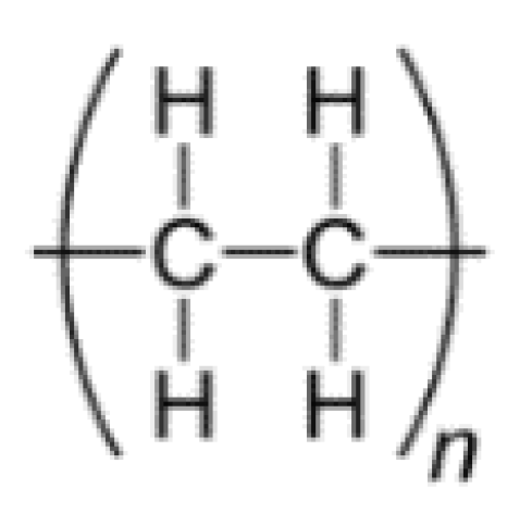
3.1. Properties of PE Membranes

In general, PE is composed of a –C2H4–repeating unit (Figure 1). The polymer is an odorless and non-toxic semi-crystalline polymer with good acid and alkali corrosion resistance, low water absorption, and excellent electrical insulation. However, PE has a relatively low melting point (around 120 °C) and low temperature resistance [continuous service temperature (CST)] of 60–80 °C for low density (LDPE) and 80–100 °C for high density (HDPE). Based on these properties, the two main methods to prepare PE microporous membranes are thermally induced phase separation (TIPS) and MSCS [20].

3.2. TIPS

As the main method to produce microporous PE membranes, TIPS is distinguished from other methods because the membrane microstructure can be more easily controlled [52,55,56,57,58,59,60,61,62]. For example, compared to NIPS, the homogeneous solution from which the membrane is formed is converted into a two-phase mixture via thermal energy removal, which is faster than by non-solvent exchange from the solvent, as described later [5].

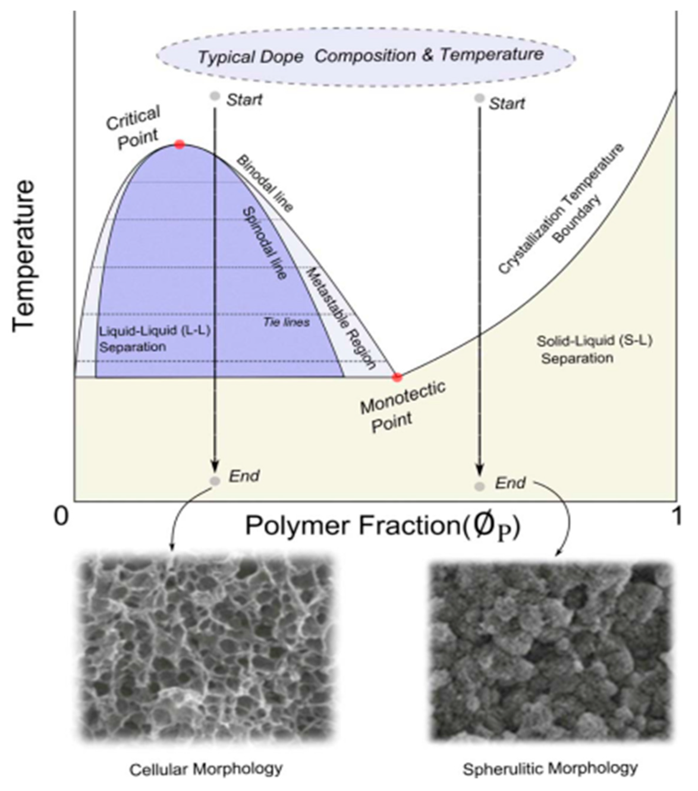
3.2.1. TIPS Processing

The general procedure for TIPS is as follows. Firstly, to form a homogeneous mixture, a certain amount of a high-melting point polymer and a low molecular weight diluent (liquid or solid) mixture is placed between a pair of stainless steel plates. A Teflon film with a square opening in the center is inserted between them to adjust the membrane thickness, as shown in Figure 2. The sample is melted by heating at elevated temperature with pressure. It should be pointed out that during this step, the initial temperature (T1) must be lower than the boiling point of the diluent and is typically 25–100 °C higher than the melting temperature (Tm) or the glass transition temperature (TG) of the neat polymer. Secondly, a homogeneous mixture is formed into the desired shape, which is usually a flat sheet, tube, or hollow fiber. Thirdly, a phase separation is induced by cooling at a controlled rate (thermal quenching). Then, the diluent is typically removed by solvent extraction. Finally, a micro-porous structure is produced by removing the extractant (typically by evaporation) [4]. The key point of the technology is to induce a phase separation in the membrane fabrication by removing the thermal energy of a homogeneous dope solution. Hence, the TIPS process is a balance between phase inversion path, polymer-solvent thermodynamics (interaction), cooling kinetics, extractant selection, and drying condition.

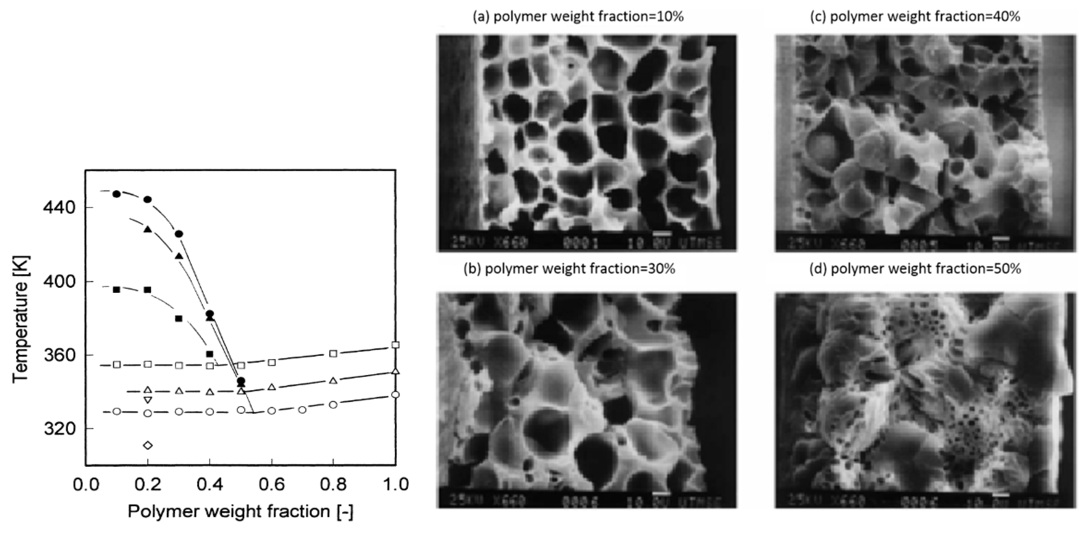
3.2.2. Effect of TIPS Conditions on the Membrane Morphology

The TIPS process for membrane formation can be represented in terms of a temperature–composition phase diagram. As shown in Figure 3 [63,64], the membranes produced via TIPS often follow two different paths: a solid–liquid (S–L) or liquid–liquid (L–L) separation with subsequent crystallization [65]. Several investigations showed that the phase separation mechanism significantly alters the resulting membrane structure [4,5,65,66]. At the same time, the membrane performance strongly depends on the membrane pore size and porosity. As a consequence, a good control of the microporous structure is of the utmost importance in membrane fabrication [52].
Usually, when the polymer concentration is above the monotectic point (typically >30%), the dope solution goes through the crystallization temperature boundary then directly enters the solid–liquid (S–L) separation region. Conversely, the phase separation proceeds via liquid–liquid separation with subsequent crystallization at relatively lower polymer fractions. Note that if the initial polymer content in the casting solution is lower than the critical point, a continuous solvent-rich phase and a discontinuous polymer-rich phase could be formed. As a result, the final products are powders instead of a solid membrane. If a suitable polymer concentration is selected, the separation path plays a critical role on the membrane morphology [63].
Solid–liquid phase separations (S–L or L–S) are usually initiated by the formation of crystal nuclei via primary heterogeneous nucleation following stable nuclei growth through secondary nucleation. During the crystallization process, the amorphous polymer and the diluent are rejected by the growing crystals [5,67,68]. The microporous structures are then produced by removing the diluent between the lamellae or the spherulites. As discussed above, the driving force is the different polymer chemical potential in the crystalline and the solution phases [65], but crystallization thermodynamics and kinetics also play important roles for this phase separation to occur.
Liquid–liquid phase separation (L–L) is induced by the thermodynamic instability of the polymer–diluent system. The homogeneous polymer–diluent mixture is produced at a relatively high temperature and then undergoes an upper critical solution temperature (UCST)-type phase behavior by cooling the system entering an unstable region. The microstructure can be developed at the early stage of phase separation, and then the two-phase system enters the coarsening process. The kinetics continue to evolve in response to a tendency to reduce the surface energy associated with the interfacial area. This results in a reduction of the number of diluent droplets combined with an increase in droplet size [66,69,70,71,72,73,74]. The growth of diluent droplets finally stops when the polymer solution is solidified by further cooling under the crystallization temperature [66]. This means that, for semi-crystalline polymers, liquid–liquid phase separation is related to polymer crystallization, either simultaneously or subsequently [65]. Two important factors have mainly been considered to determine the relation between the final diluent droplets sizes and the membrane porosity: the phase separation temperature and the coarsening mechanism.
As mentioned above, different separation mechanisms are associated with the porous structure formation. When a specific route is selected, the final membrane pore size and pore structure strongly depend on the cooling conditions; rapid cooling provides several nuclei and leaves shorter time for crystal growth, while slow cooling provides longer times for crystal growth, resulting in membranes prepared via the L–L separation, which usually exhibit a porous, cellular-like and/or bicontinuous structure. Conversely, membranes formed via S–L separation show fuzzy spherulitic (sphere-like) structures. The parameters affecting the final membrane morphology are summarized in Table 2.

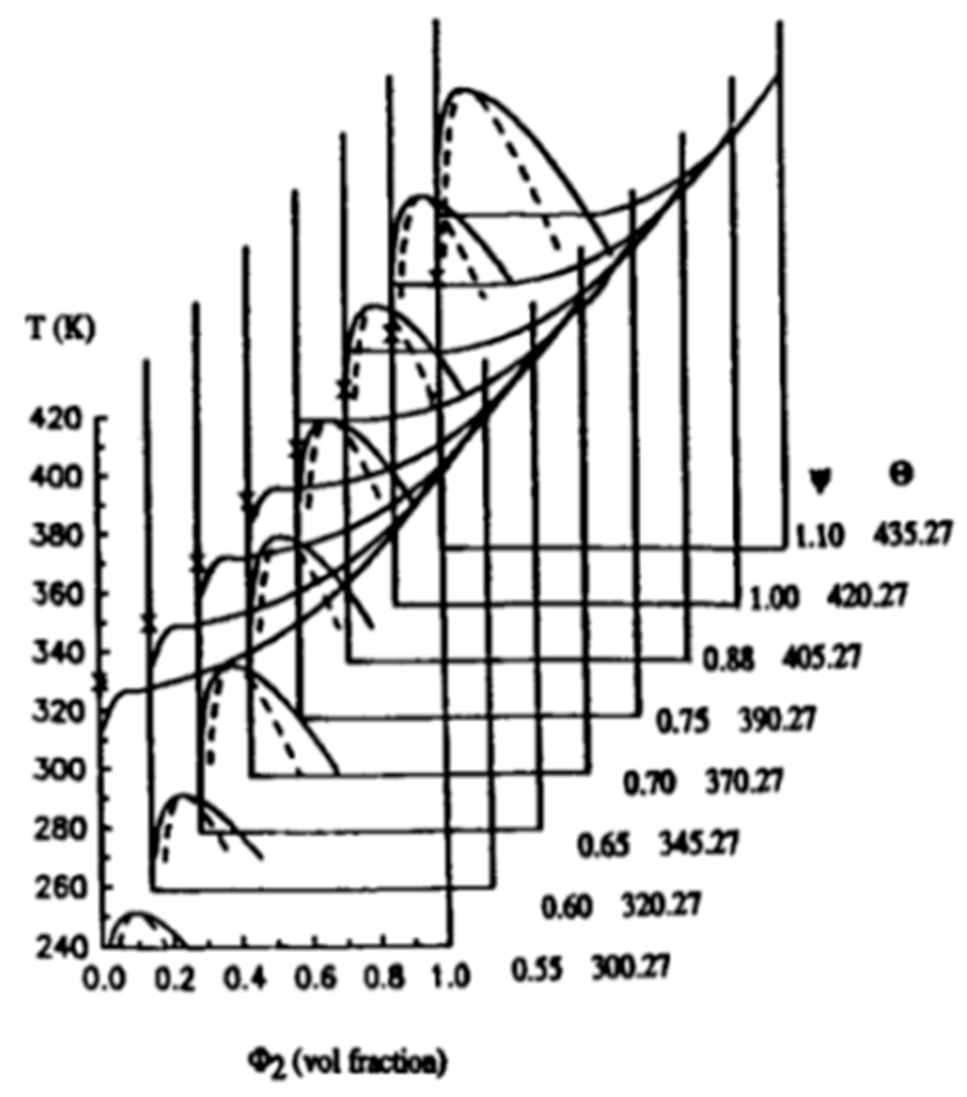
3.2.3. Effect of the Polymer–Diluent Thermodynamics on the Membrane Morphology

For a semi-crystalline polymer–diluent system, miscibility is the main factor to determine whether a solid–liquid or liquid–liquid phase separation occurs. Miscibility can be quantified by the interaction parameter (χ) [4]. As shown in Figure 4a, the interactions between the blends are favorable when χ is negative and minimum. When cooled, the semi-crystalline polymer–diluent system has no liquid–liquid phase separation and only undergoes a solid–liquid phase separation throughout most of the composition range [65]. Figure 4b shows an unstable region below the melting point depression curve, where the interactions are less favorable (χ increasing). The blend becomes unstable, and both crystallization and liquid–liquid phase separation can take place [4,5,65,80]. According to Figure 4c, when the interactions are weak (high χ), a liquid–liquid phase separation may precede the crystallization of semi-crystalline polymers [65,81,82]. In this case, the possibility of phase separation is determined by the initial polymer concentration and the relative crystallization kinetics. Figure 4d presents a case where χ is always positive, and the amorphous phase can only occur via liquid–liquid phase separation [65,83,84,85]. This means that the phase separation process can be successfully controlled by systematically varying χ for the semi-crystalline polymer–diluent mixture. According to the Flory–Huggins lattice theory, the following relation is available [8]:
χ = ½ + Ψ θ/(T − 1)
where Ψ is the entropy parameter, and θ is the theta temperature of the polymer solution. By changing the interaction parameter χ (variation of Ψ and θ separately), it is clearly observed in Figure 5 that the reduction of the L–L phase separation temperature curve is more significant than that of the melting point [8]. This may provide a situation where the L–L phase separation can occur below the L–S boundary. It is important to note that the position of the polymer–diluent mixture phase boundary is the most important factor controlling the droplet size of TIPS membranes [59].
In general, by changing the polymer–diluent composition, various interaction parameter χ can be obtained. Three methods are generally used:
  • by varying the diluent types,
  • by varying the components molecular weights,
  • by varying the polymer concentrations.
However, for PE membranes, limitations exist for the different diluents that can be used, since only a few diluents’ molecular weight and melting points are close to PE. This results in only a few diluents being available to prepare PE membranes. The most common ones are phthalates, esters, mineral oils, normal paraffins, or isoparaffins [52,55,58]. Nevertheless, introducing a third component in the solution can change the position of the binodal line, resulting in a wide range of membrane morphology. Hence, several researchers used solvent mixtures to obtain tailor-made membrane structure and performance. However, most of these diluents are toxic (especially phthalates and esters), further limiting the range of possible options. An interesting trend for TIPS is that potential green and sustainable solvents are gaining interest to meet the increasingly stringent government regulations [86,87].
Components molecular weight is also a narrow range to choose from. For example, PE can be classified into four main classes: linear low density polyethylene (LLDPE), low density polyethylene (LDPE), high density polyethylene (HDPE), and ultra-high molecular weight polyethylene (UHMWPE). Thus, for each molecular weight range, matching diluents are required.
Table 3 summarizes the recent works related to the effect of polymer–diluent composition on the PE membrane morphology. It can be seen that, although the range of choice is narrower by varying the diluent types or varying the components molecular weight, the morphology of PE membranes is effectively controlled because the membrane fabrication process is determined by the interaction parameter χ.
The third method is by controlling the polymer concentration, because the blend composition determines the phase boundaries of the system. The mixture undergoes a liquid–liquid phase separation with subsequent crystallization of the polymer at low initial polymer concentrations and solid–liquid phase separation at high initial polymer concentrations [4,65,80]. As shown in Figure 6, liquid–liquid TIPS occurs prior to crystallization for the range of 10 to 40 wt. %, while at 50 wt. %, the crystallization occurs prior to the liquid–liquid separation, and spherulites are formed. It can clearly be seen that different separation processes play a critical role in the membrane morphology. In the 10–40 wt. % range, spherical pores are well connected, and these structures are suitable for membrane separation applications. On the other hand, isolated spherical pores are produced at 50 wt. % [66].

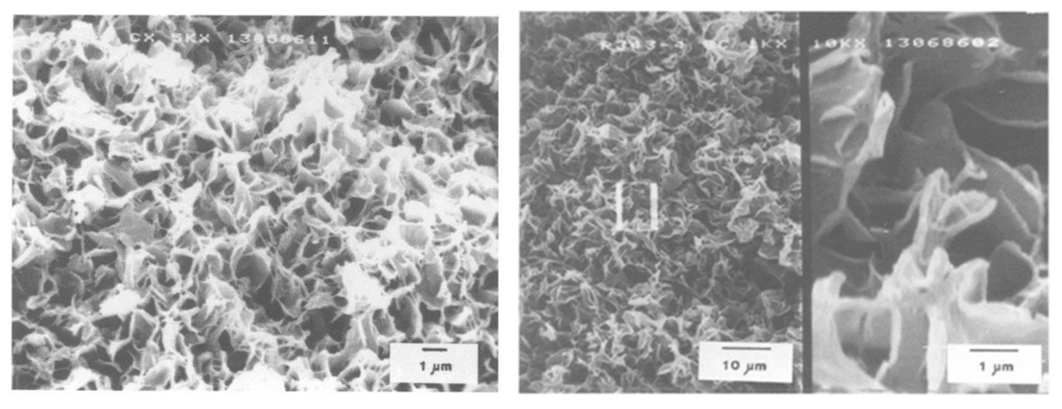
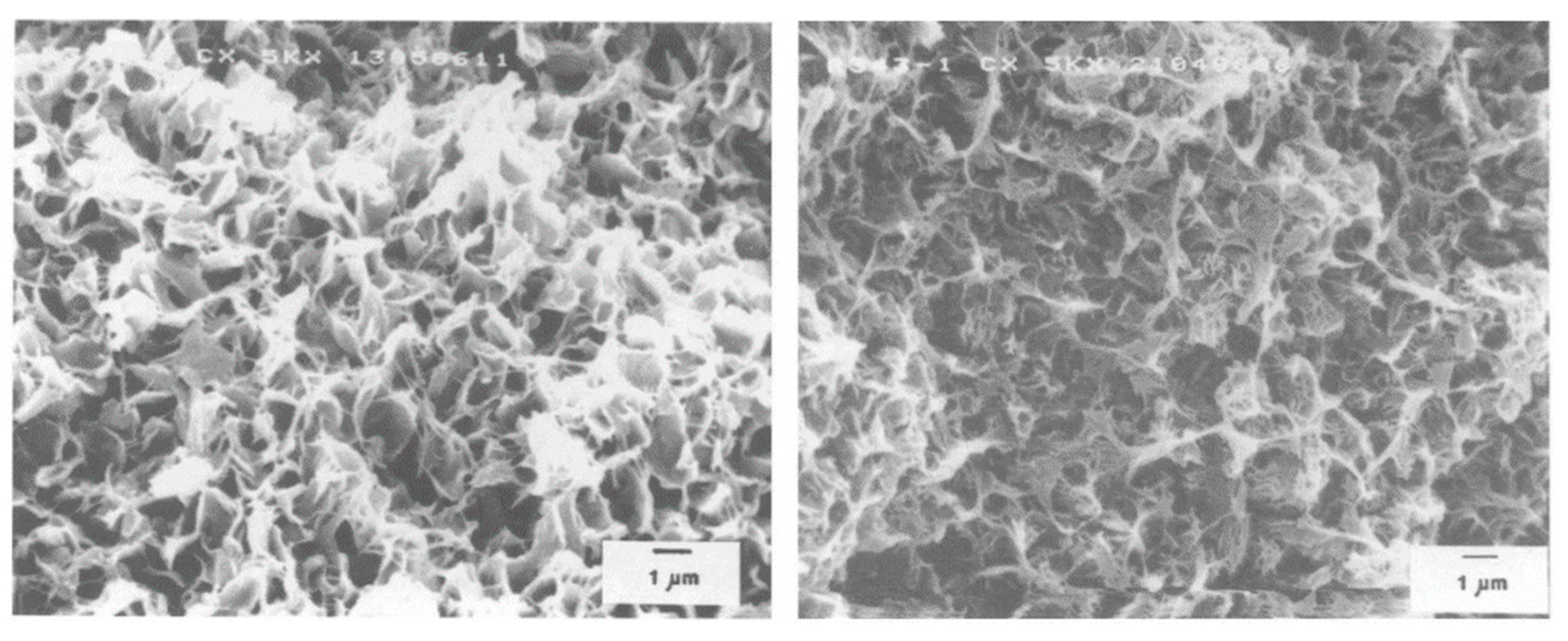
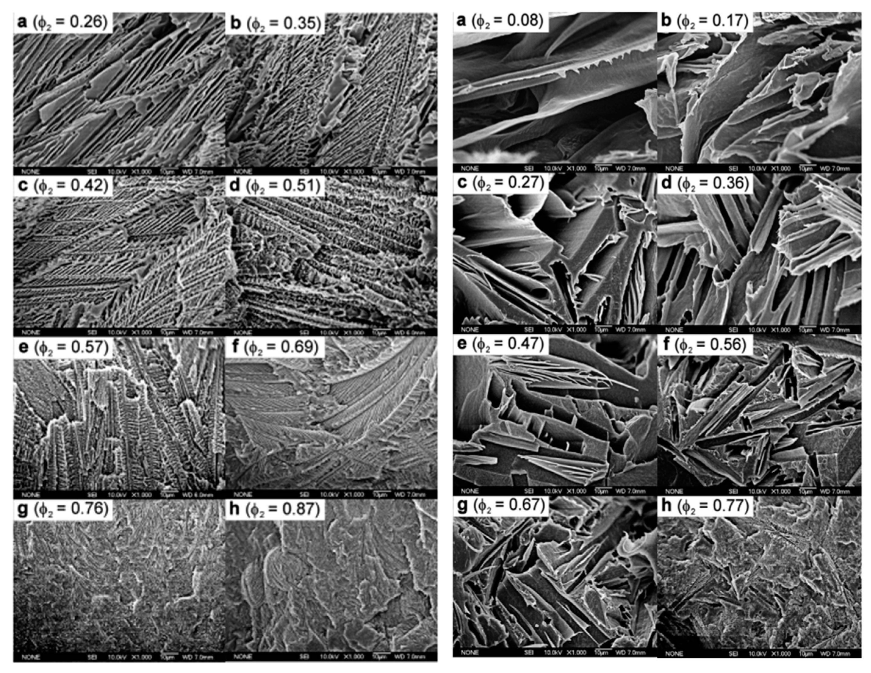
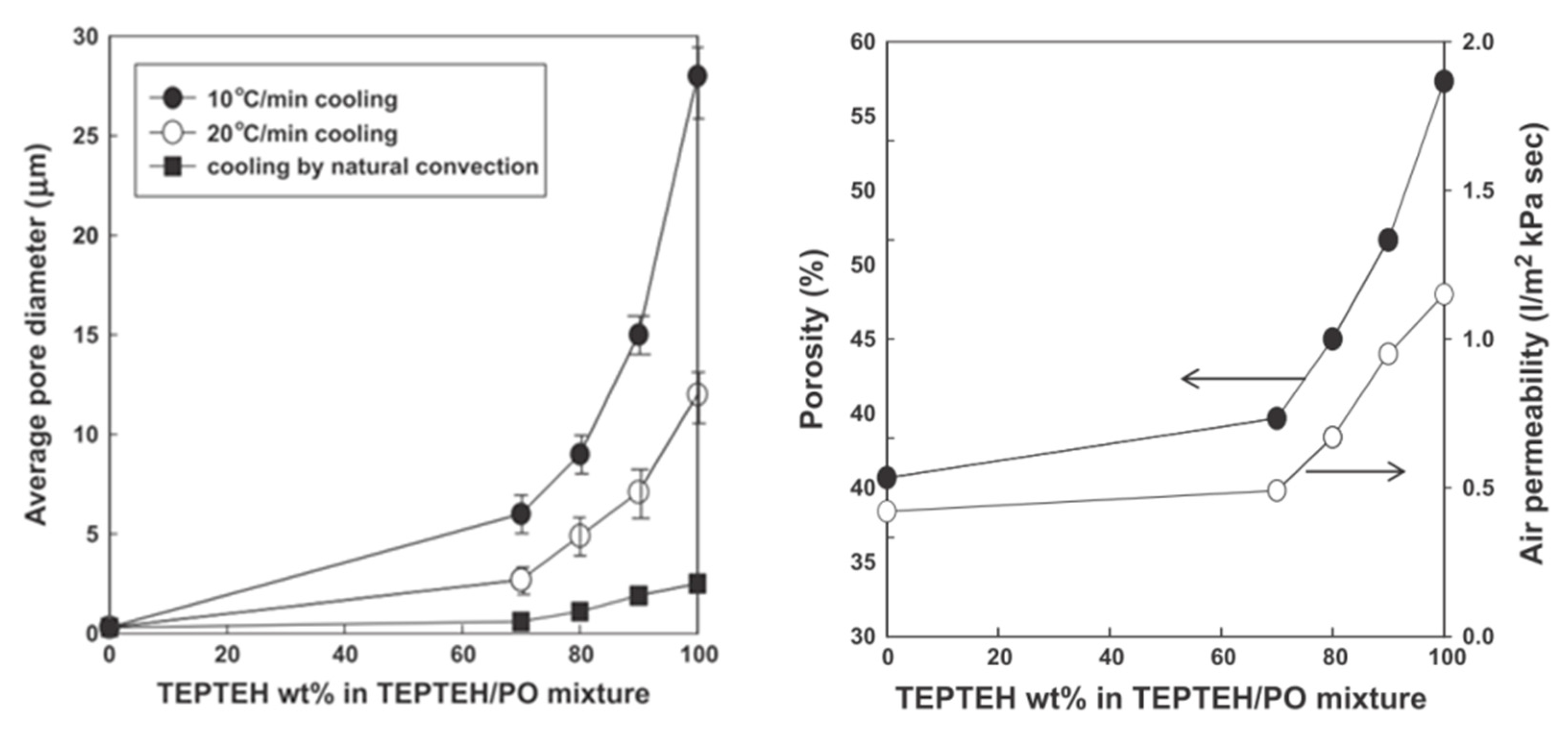
3.2.4. Effect of Phase Separation Kinetics on the Membrane Morphology

An upper critical solution temperature (UCST) is defined as a system undergoing phase separation as the temperature is lowered. As the temperature is increased, systems undergoing phase separation are said to have a lower critical solution temperature (LCST) [65]. A focus on TIPS for UCST systems is made next.

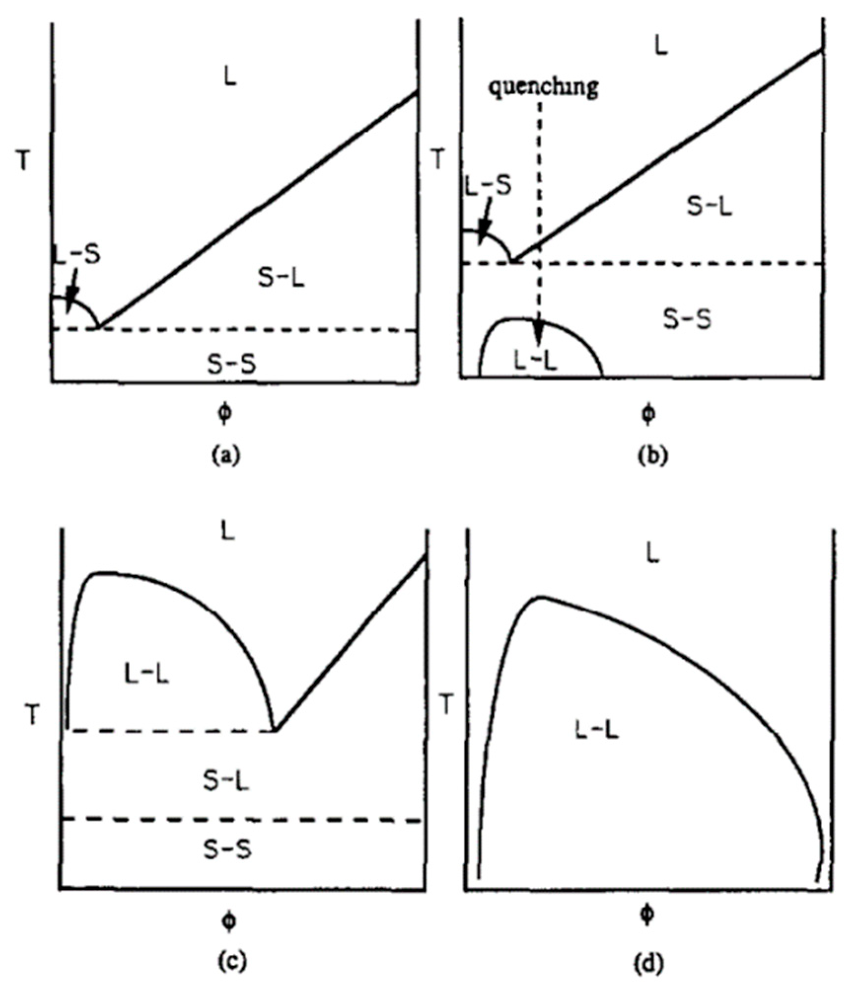
Solid–Liquid Phase Separation

In L–S separation, since the membrane micropores are produced by removing the diluent expelled from the growing crystal, polymer crystallization kinetics—and in some cases, that of solvent crystallization—play a major role. It can be shown that the pore size in L–S separation follows specific trends:
(I) Decreases with increasing quench temperature and cooling rate
Since lower nucleation rate and longer growth period are associated with slower cooling, this allows more time for PE crystal growth without qualitatively altering the structure. Consequently, the membrane pores morphology after extraction is directly affected. Comparison of the SEM results (Figure 7) from the S–L phase separation of a 19 wt. % HDPE in mineral oil solution quenched in water via controlled cooling from 175 to 30 °C shows that the membrane morphology was clearly affected by the cooling rate. In the quenched sample, the homogeneous mixture is virtually frozen, i.e., the spherulites position is fixed, leading to the pores formed by extracting droplets densely distributed with smaller pore sizes. For slowly cooled samples, the diluent is expelled from the growing spherulites, then the diluent diffuses to the surface, leading to a local concentration gradient and some lamellae gradually crystallizing from the polymer–diluent mixture [5].
(II) Decreases with increasing polymer concentration
In the highly polymer-rich case, since the initial composition is beyond the eutectic composition, the L–S phase separation is triggered by the polymer crystallization. As shown in Figure 8, pore sizes decrease with increasing polymer concentration. There are two main reasons for this phenomenon. Firstly, a change in the phase separation temperature is consistent with polymer concentration change, as reported in Figure 4. The temperature difference between the phase separation temperature and the crystallization temperature increases with increasing polymer concentration. This results in greater driving force and longer time for crystal growth. Thus, spherulite size increases as the polymer concentration increases, as less space is available for the exuded dilute droplets. Secondly, the viscosity of the polymer-rich matrix phase increases with the polymer concentration. Thus, it is more difficult for the diluent droplets to flow and aggregate. After the extraction of the diluent droplets, the membrane has a corresponding pore size distribution.
Figure 9 shows that, for some diluents, when their crystallization temperature is higher than the polymer, diluent crystallization occurs before the polymer. This phenomenon continues until the eutectic solidification begins. This induces a fixed structure—an integrally skinned porous membrane produced by extracting the diluent crystals from the solidified samples [90].
(III) Decreases with the presence of nucleating agents
Due to the extremely high nucleation density, the polymer crystals size is much smaller with the presence of a nucleating agent (heterogeneous nucleation). This substantially affects the membrane porosity in terms of higher pore numbers and smaller pore sizes [5,94].

Liquid–Liquid Phase Separation

As shown in Figure 10, the phase diagram of LDPE palm-oil determines the L–L phase separation prior to polymer crystallization. SEM can provide some information about the type of porous structure and how the polymer volume fraction affects the pore size, which has a high influence on the membrane performance, such as water vapor flux [7].
As shown in Figure 11, the PE/(TEPTEH (triethylolpropane tris(2-ethylhexanoate))/PO) mixture exhibits a UCST type phase separation; the average pore size and the membrane porosity increase with increasing TEPTEH concentration in the diluent mixture, leading to increased air permeability [52]. Moreover, the pore size increases more when the system is slowly cooled—as opposed to fast cooling—confirming the influence of cooling kinetics.
In L–L separation, microporous structures are produced by removing the diluent droplets with an extractant. Thus, the membrane morphology is determined by the final diluent droplets’ size. A summary of the droplet growth process is described in Section 3.2.2. It can be concluded that the droplet growth rate in liquid–liquid TIPS is dependent on the polymer–diluent interfacial tension, which is influenced by several parameters as follows [4,6,52,55,56,58,59,66,69,70,71,72,73,74,83,88,95]:
  • increasing with increasing volume fraction of the droplet phase,
  • decreasing with increasing viscosity of the polymer-rich matrix phase,
  • decreasing with decreasing the temperature difference between the phase separation temperature and the crystallization temperature,
  • decreasing with increasing cooling rate.

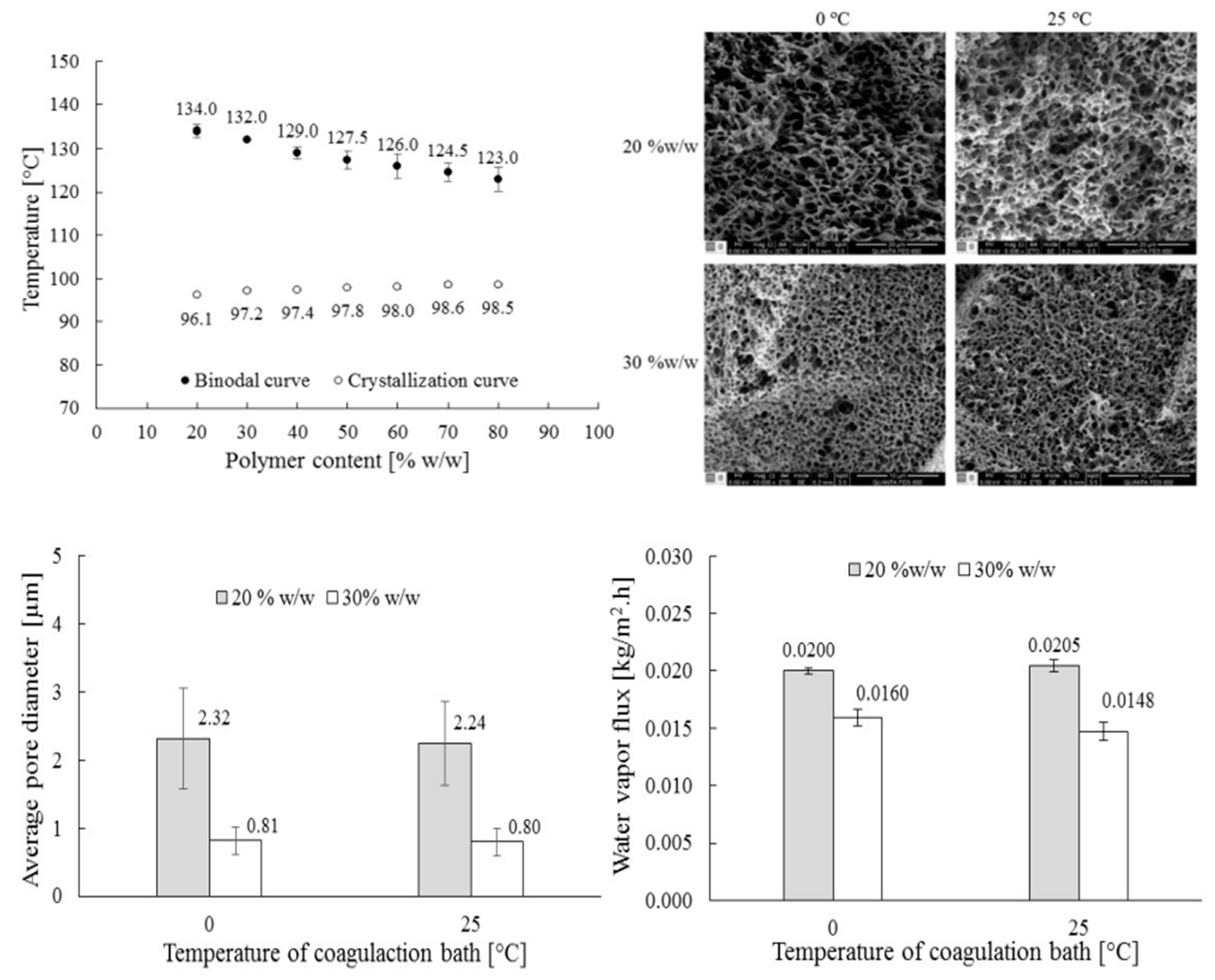
3.2.5. Effect of Extractant Selection and Drying Conditions on the Membrane Morphology

As shown in Table 4, 10 extractants were used to remove the diluent in the TIPS process to produce microporous PE membranes [89]. The membrane dimensions decreased with increasing surface tension and boiling point, leading to decreasing porosity, pore size, and permeability. Obviously, by varying the diluent and the extractant in the TIPS process, it is possible to control the membrane morphology and performance [89].

3.3. MSCS

In 1974, a polyolefin microporous flat membrane via melt-spinning coupled with cold stretching process was firstly reported by the Celanese Corporation. To commercialize the membranes and increase the water flux [20], changes to the membranes configuration was proposed by the Mitsubishi Rayon Corporation in 1977 [96]. The MSCS technique to fabricate hollow fiber membranes was developed, and these microporous membranes gained popularity by being used in several applications such as blood oxygenators, desalination equipments, biosensors, ultra-pure water purifiers, and membrane distillators [20,22,96,97,98].
In the MSCS process, a neat hard-elastic polymer melt is firstly spun. The precursor material must have specific properties such as high initial elastic modulus and elastic recovery [99]. In a subsequent cold-stretching step, the material is characterized by a “row nucleated crystalline lamellar” structure composed of stacked crystalline lamellae aligned parallel to the drawing direction and formed by elongational stress and then recrystallized [100]. Finally, micropores are produced by the mechanical force acting on the material and are completed during the cold-stretching step. The mechanism of micropore formation via MSCS has been reported [101,102]. It was shown that, upon stretching, the crystalline lamellae separates due to the rows of crystalline lamellae, which are in turn arranged normal to the drawing direction, and several voids are formed and interconnected. As a result, the micropores are formed in the membranes. This means that the effect of external forces is the main origin for the porous structure formation [20,22].
Compared with TIPS, the MSCS process is more difficult to control the pore size. It also requires that the precursor materials for preparing the microporous membrane are crystalline polymers such as PP [20,103,104,105], PS [106] and PE [97,98,101,107,108,109]. Furthermore, since PP has more side groups on its molecular chains, PE is a better choice in view of chemical stability and membranes properties. However, the use of diluents and extractants in the TIPS process results in waste solvent problems. Thus, the MSCS process is more environmentally friendly, since MSCS only uses a neat polymer. This also means that there is no phase separation, and its control is relatively easy [20,22].

3.3.1. Effect of Temperature

In the MSCS process, the annealing temperature is an important factor affecting the micropores formation process and the pore structure of PE hollow fiber membranes [99]. It is known that the crystalline structure is reorganized when PE membranes are annealed. The aligned PE crystallinity is effectively characterized by birefringence (BR) measurements. When recrystallization occurs, more “perfect” crystalline structures are produced, and the BR increases [99,110]. Some researchers quantitatively examined the BR variation with respect to the annealing temperature [20,99]. It was shown that increasing the annealing temperature increased the BR, indicating that the micropores became more oriented. It was also found that the lamellar thickness further increased at higher annealing temperature.
As shown in Figure 12, the unique microporous structures showing a slit-like shape in a pocket fashion are highly affected by the annealing temperatures. Lee et al. [99] suggested that the effect of annealing temperature on the pore structure is mainly by changing the concentration and the strength between the stressed tie molecules in the amorphous region and the crystallites lamellae. By increasing the annealing temperature, the segments of loose tie chains can be drawn into the crystallites, leading to thicker lamellae and higher overall degree of crystallinity. Elyashevich et al. [111] suggested that higher annealing temperature results in narrower length distribution of tie chains, meaning that more stretched tie chains are produced in the inter-lamellar regions. Chen et al. [110] also confirmed that the lamellae thickness increased with increasing annealing temperature up to the peak melting temperature, but higher temperature led to the formation of long-period lamellar spacing.
It is assumed that the application of an annealing temperature during the stretching process can control the final structure. Xi et al. [22] suggested that it is necessary to control the stretching process with a proper temperature in MSCS, such as the application of a two-step stretching process. In the first stretching step, the interaction between the lamellae is mainly broken under the stretching of annealed hollow fibers, and then microvoids are created on the fiber wall. Subsequently, the second stretching step results in the formation of larger micropores. In order to smoothly develop the microvoids into larger micropores, a suitable temperature below the PE melting point is the main factor to prevent microvoids collapse during the second stretching process.
As a next step, the morphology (porosity) and the permeability (Gurley value, N2 permeation) of PE hollow fibers are used to determine the performance variation by increasing the stretching temperature, as shown in Figure 13, where the Gurley value is an indicator of air permeability. Low Gurley values are associated with high air permeability. In Figure 13, the Gurley values are normalized by film thickness [112]. It is known that flexible molecular chains in the amorphous region of crystalline polymers have less resistance; therefore, molecular chains have higher mobility and orientation possibility under the applied external force and temperature. At a relatively high temperature, more molecular chains would be drawn out from the amorphous region and rearranged into fibrils along the stretching direction. Thus, higher porosity is developed by bridging the separated lamellae. This significant improvement can offer higher air permeability by optimizing the annealing temperature. This is suitable for applications such as distillation and seawater desalination [22].
In addition to the annealing temperature, the spinning temperature also affects the crystallinity and the degree of orientation of the hollow fibers. For a polymer melt, the viscosity increases with decreasing temperature, which is necessary to increase the stress in the spinning process, leading to a higher level of orientation in the fibers. Therefore, hollow fibers spun at higher temperature have lower birefringence, higher bubble point pressure, smaller pore size, and more uniform pore distribution [20].

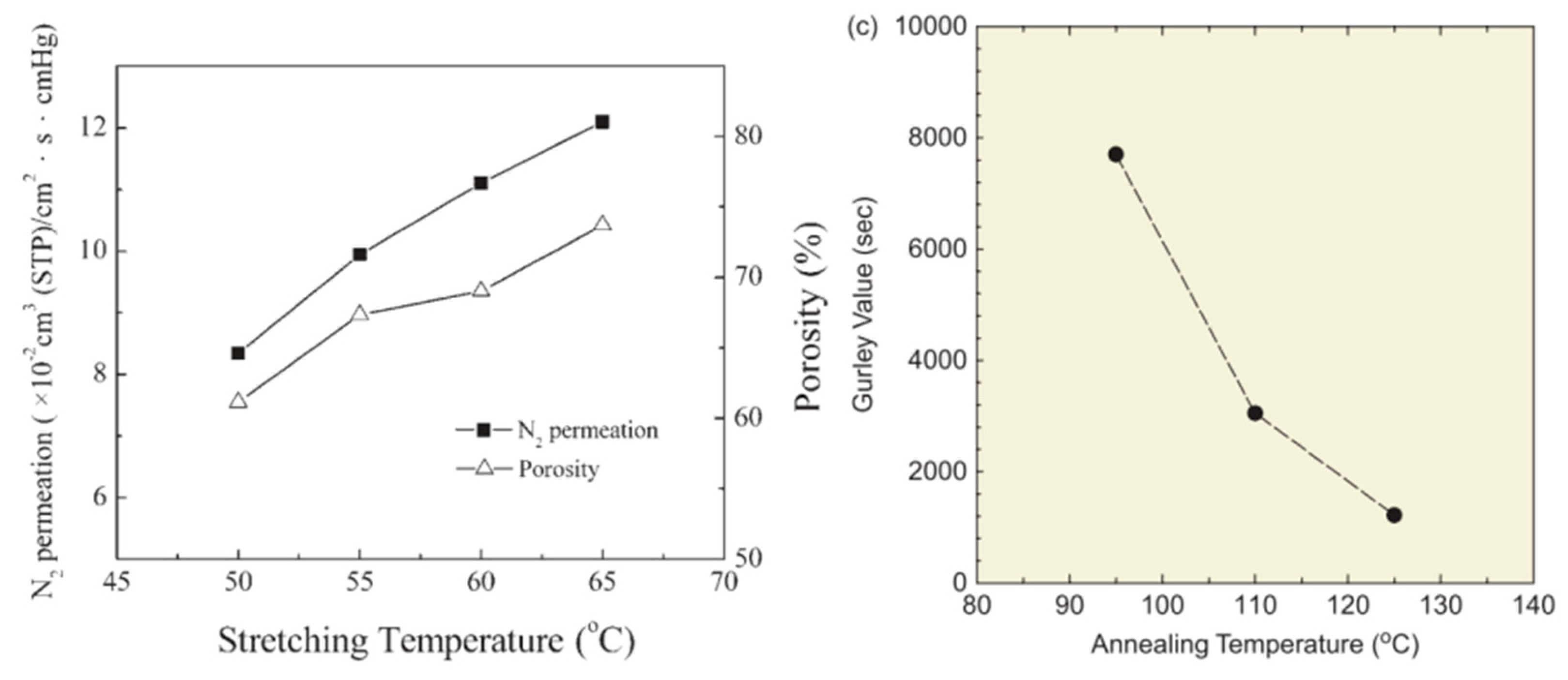
3.3.2. Effect of the Stretching Ratio

The degree of melt extension can be described by the stretching ratio (R = V2/V1) defined as the ratio between the extrusion speed (V1) and the take-up speed (V2). This parameter mainly governs the morphology in terms of pore size, distribution, orientation, geometry, etc.
The stretching ratio has been reported to affect the stress along the fiber direction [99,102]. For example, increasing the stretching ratio from 1.35 to 2.28 led to more elongated fibrils, and the space between the separated lamellar crystals became larger [22]. Also, increasing the stretching ratio from 2.3 to 3.3 led to more uniform pore size distributions, and the amount of pores (diameter < 1 µm) rapidly increased to become the main part of the pore size distribution. Several theories were proposed to explain these results [113,114]. Firstly, from a position originally perpendicular to the fiber direction, the lamellae rotated to a position parallel to the fiber direction. Secondly, molecular chains in the lamellae were oriented, and then the microvoids linked by fibrils were formed. Thus, higher stretching ratio means that more fibrils bridging the separated crystalline lamellae are developed. Therefore, microvoids or micropores continuously grow in size. However, there is a critical stretching ratio for which the fibrils in the microvoids break, resulting in the formation of cracks and leading to poor structures [22].
By increasing the stretching ratio within a reasonable range, higher porosity and permeability of PE microporous hollow fiber membranes can be produced. Experimental results confirmed that the relationship between the stretching ratio, the porosity, and the N2 permeation of PE membranes is directly correlated to the stress range. When the ratio increased from 100 to 170%, the N2 permeation increased by 31%, while the porosity increased by 13% [102].

3.3.3. Effect of the Stretching Rate

To get a better understanding of the stretching rate effect on the PE hollow fiber membrane structure and properties, the mechanism of resistance to stress cracking is used. During the stretching process, the formation of fibrils recovered in the PE hollow fiber wall and break-up in the hollow fiber wall occur at the same time. With an increased stretching rate, more fibrils are formed and destroyed. As a result, the amount of smaller size pore (average pore size < 1 µm) increases. As shown in Table 5, under a relatively high stretching rate, the average pore sizes slightly decreases, and the pore size distribution gets more uniform, and the N2 permeation and the porosity further increase with a more uniform porous structure, leading to better performance of the PE hollow fiber membranes with increased stretching rate [22].

3.3.4. Effect of Cooling Ways

Luo et al. [21] prepared hollow fiber membranes by MSCS and selected air, water, and di-isononyl-cyclohexane-1,2-dicarb-oxylate (DINCH) as the cooling media to investigate the effect of various cooling methods and cooling rates on the membrane morphology. The results showed that when water and DINCH were used as the heat transfer medium, a layer of amorphous phase and fewer uniform pores—which only had a small part of the slit-shaped pores—were obtained on the surface, because the fast cooling rate froze the surface molecules and decreased the crystallinity and orientation. However, when air was used as the cooling medium, higher crystallinity and better orientation of the annealed hollow fibers were obtained, mainly due to the slow cooling rate. As a result, hollow fiber membranes prepared by slow cooling had better pore interconnectivity and performances [21].
As demonstrated above, although several parameters must be controlled in MSCS, the key factors significantly influencing the membrane morphology can be classified into temperature, stretching ratio, stretching rate, and cooling conditions. The stretching ratio and the stretching rate mainly govern the crystalline lamellae alignment, while the stretching temperature and the cooling conditions significantly influence the number of stretched tie chains and fibrils bridging the narrow cracks [22,99,102,103,110]. It is possible to control these four key parameters inside an optimum range during the stretching process to improve the porous structure and the overall performances of hollow fiber membranes. For higher membrane porosity and more uniform pore distribution, the following strategies can be used:
  • increasing the annealing temperature within the peak melting temperature range,
  • increasing the stretching ratio within a reasonable range,
  • increasing the stretching rate below a critical value (membrane break-up),
  • decreasing the cooling rate.

4. PDMS Membranes

Based on the outstanding advantages of PDMS, such as non-toxicity, high hydrophobicity, chemical resistance, gas permeability, optical transparency, environmental friendliness that does not bio-accumulate, flexibility, low costs, and good molding capability [34,115], through-hole PDMS membranes found wide applications in the biomedical and chemical fields, such as sterile filtration, cell sorting, biomolecular separation, termed organs-on-a-chip systems, microfluidic devices, thin film extraction, lab-on-a-chip devices, micro total analysis systems, and permeation passive samplers [34,115,116,117,118].
A number of methods have been reported to fabricate PDMS through-hole membranes [33,34,119,120]. A focus on micromolding, imprinting/soft molding, manual punching, and the novel three-dimensional (3D) printing technique is presented here.

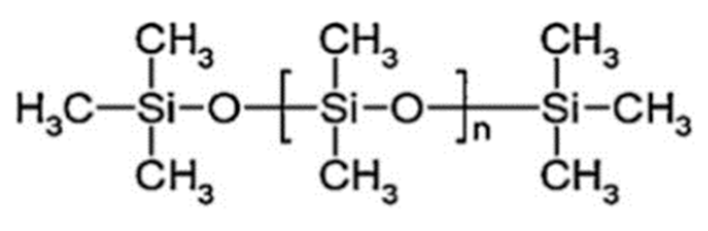
4.1. Properties of PDMS Membranes

PDMS is made of a flexible (Si–O) backbone and a repeating (Si(CH3)2O) unit (see Figure 14). For PDMS, the molecular weight varies from 1 × 10⁴ to 6 × 10⁴ gmol−1 due to the amount of (Si(CH3)2O) repeating units. Consequently, several material properties, such as viscoelasticity, are affected [121]. Furthermore, these viscoelastic properties can be modified by cross-linking (vinyl cross-linking) [122] or by filler addition (silicon dioxide) to the polymer network to meet the requirements of the current applications [123]. Table 6 lists some typical PDMS properties, especially because it is hydrophobic and translucent [115,124]. Today, PDMS is widely used in nanomembranes because of its remarkable advantages, such as chemical resistance, mechanical properties, gas permeability, optical transparency and biocompatibility, as well as its high molding capacity, leading to the production of nanomembranes and micro/nanofluidic systems [34,37,120,125].

4.2. PSμM

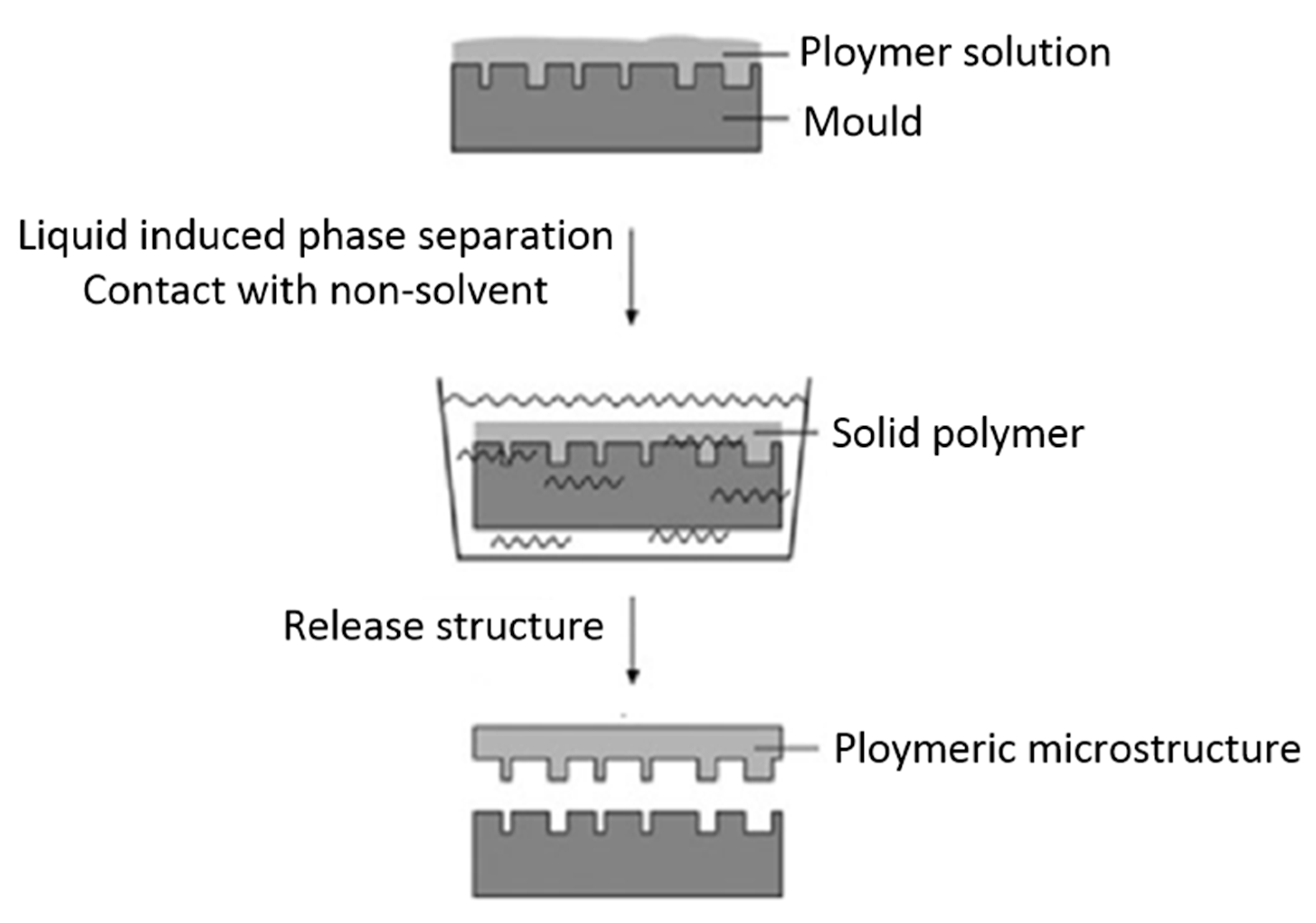
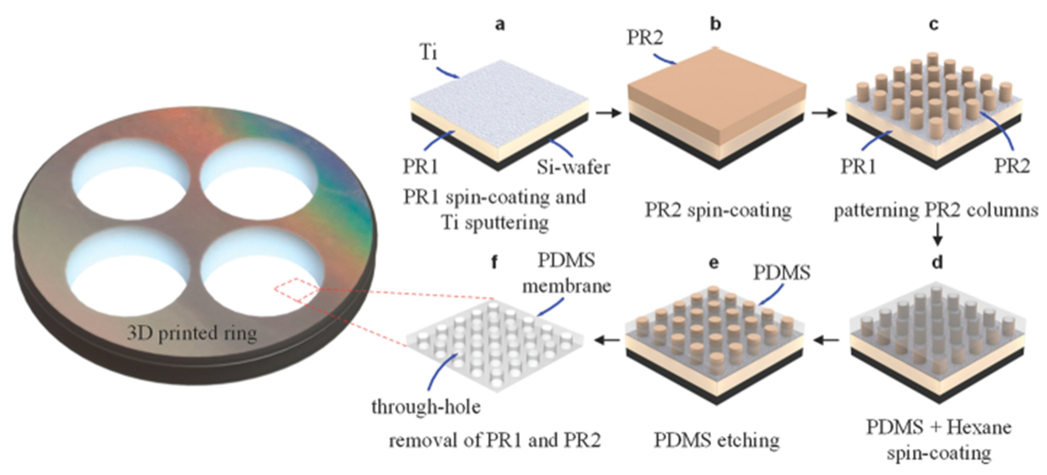
4.2.1. PSµM Processing

A novel micromolding process based on polymer phase separation has received increasing attention in recent years, and Figure 15 presents a schematic representation of this method. The main process of spin-coating on molds consists of four steps as follows [32,33,34]:
  • Firstly, fabrication of dedicated patterning systems occurs. In most case, an additional coating of anti-sticking layers on the molds prior to the injection of the pre-polymer is needed to release the nano-membrane from the mold.
  • Subsequently, there is prepation of a PDMS solution with a specific composition, and then the solution is spin-coated over the fabricated molds.
  • To open the through-holes, the cured PDMS membranes are further processed via etching or thermal compression.
  • Finally, remove the photoresist posts to expose the through-holes.
Although various methods such as conventional photolithography processes (soft-lithography), electron-beam lithography [127], laser interference lithography [128], or focused ion-beam milling [129,130] can be used to pattern the nano-columns in step 1, the difficulty in the fabrication of patterned columns (SU-8) at sub-μm diameter ranges limits the use of PDMS membranes for nanometer-sized through-holes. Furthermore, patterning such molds is labor intensive and requires dedicated patterning systems, which are expensive [34].
For step 2, the solution composition and concentration play critical roles in the PDMS membrane morphology. Thangawng et al. [131] reported on the effect of different PDMS ratios in hexane on the membrane thickness. The spin rate and the duration were kept constant at 6000 RPM and 150 s, respectively, but they used three different substrates: silicon, a Si coated photoresist, and a Teflon (AF) coated Si. The results in Figure 16 show that the membrane thickness was independent of the substrate types. However, the thickness decreased with an increasing amount of hexane in the solution. Lötters et al. [132] obtained similar results by showing that the membrane thickness could only be reduced down to 3 μm if the PDMS was not diluted with a curing agent. Thus, in most samples, a PDMS pre-polymer:curing agent ratio of 10:1 was used to achieve highy flexible and ultra-thin PDMS membranes.
For step 3, the first task is to select a method to open the through-holes and cure the membrane. This can be done via dry etching, plasma etching, chemical etching, thermal compression, and blowing. The processing parameters (time, pressure, and power) must be controlled to obtain the tailor-made PDMS membranes.
For step 4, the through-hole PDMS membrane can be obtained by demolding the cured PDMS layer from the mold using chemical reagent and completely dissolving the sacrificial photoresist (PR) structures [34]. Another method for a perforated membrane is to directly peel off the membrane from the molds [33,133].

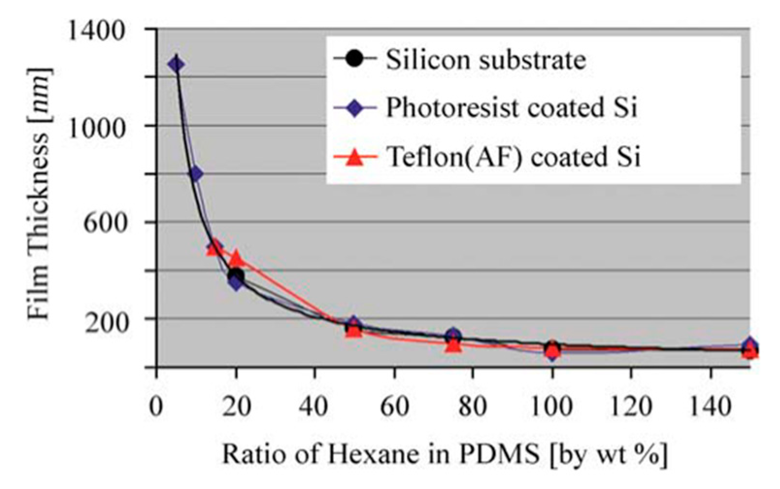
4.2.2. Effect of Processing Parameters on Membrane Morphology

Etching Time

Tibbe et al. [34] used the soft-lithography method to fabricate sacrificial PR arrays with different hole interspacings of 3, 5, and 10 μm as molds. Secondly, a 1:10 PDMS:hexane solution was spin-coated over the fabricated PR column arrays at 6000 RPM for 3 min and subsequently left to cure. As a result, a PDMS layer thinner than the column height was produced. Thirdly, reactive plasma etching of the PDMS membrane was conducted in a reactive ion etching system by precisly controlling the etching time and the etching rate by tuning the amount of gas mixture and power. Finally, the PDMS through-hole membrane was released in acetone using a 3D-printed ring as a support. By doing so, they sucessfully prepared free-standing PDMS membranes at various sub-μm thicknesses down to 600 ± 20 nm with nanometer-sized through-hole (810 ± 20 nm diameter) and over areas as large as 3 cm in diameter. The whole fabrication process is described in Figure 17. During the membrane fabrication, the researchers mainly investigated the etching time as the main parameter, which has a significant effect on the membrane morphology. Figure 18 presents the evolution of the PDMS through-hole membranes etched for various times. The average thicknesses of the PDMS through-hole membranes at 0, 15, 30, 45, and 60 s were 1345, 1170, 940, 749, and 600 nm, respectively. By increasing the etching time, the membrane thickness was thinned down to sub-μm dimensions. In addition, when spin-coating a PDMS solution over a patterned nano-column array, some unexpected breaking of the PDMS thin film is typical [134,135]. It can be concluded that the ductility of the PDMS thin films is important and related to the intrinsic flexibility of the PDMS selected.

Effect of the Power, Oxygen Partial Pressure, and Etching Time

Jo et al. [32] reported a robust and simple method for thin PDMS membrane. Firstly, the mold master was formed on a silicon wafer using an epoxy-based photoresist (SU 8) and standard photolithography procedures. Secondly, a curing agent and PDMS prepolymer (Sylgard 184 Silicone Elastomer Kit, Dow Corning) were thoroughly mixed in a 1:10 weight ratio, and the PDMS prepolymer mixture was poured onto the master mold. Then, a transparency film was placed over the poured prepolymer mixture. Next, a multilayer stack of aluminum plates, the mold master, the PDMS prepolymer mixture, a transparency film, a rigid Pyrex wafer, and a rubber sheet were used to form a compression mold. All the layers were clamped tightly during the cure. Then, the individual components were bonded together with a reactive ion etching (RIE) system. Finally, the thin PDMS membranes were peeled off from the master mold after curing. To determine the optimum conditions, the experiments studied the effect of three processing parameters: power, oxygen partial pressure, and etching time. The results showed that low power and short etching time were better than high RF power and long etching time. The optimum pressure range was 75–120 mTorr [32].

Effect of Gas Stream Pressure

Kang et al. [135] reported a simple method using spin-coating of the PDMS pre-polymer on the Si wafer followed by gas blowing followed by a recovery process to obtain well-defined, flat PDMS membranes. This method can make well-defined holes in a PDMS membrane prepared at both high and low RPM. Furthermore, it can be repeatedly and selectively used, even with the PR mold fabricated by the single-step lithography as well as two-step lithography. The air-blowing process through the nozzle was maintained for several seconds on the SU-8 patterns to remove the PDMS prepolymer from the pattern. The results showed that 8–15 kPa was the optimum pressure range. For air pressures above 15 kPa, damages on the PDMS surface for 40 μm thickness membranes were observed, while pressures below 8 kPa were too low to blow off the residual prepolymer from the PR post.
As presented above, the key parameters controlling the structure include etching time, power, and pressure. By increasing the etching time, the membrane thickness decreased. Low power and the pressure within an optimum range were better than high power with very high or very low pressure. For a clearer understanding, Figure 19 presents a schematic representation of the different factors that control the PDMS membrane morphology via PSµM.

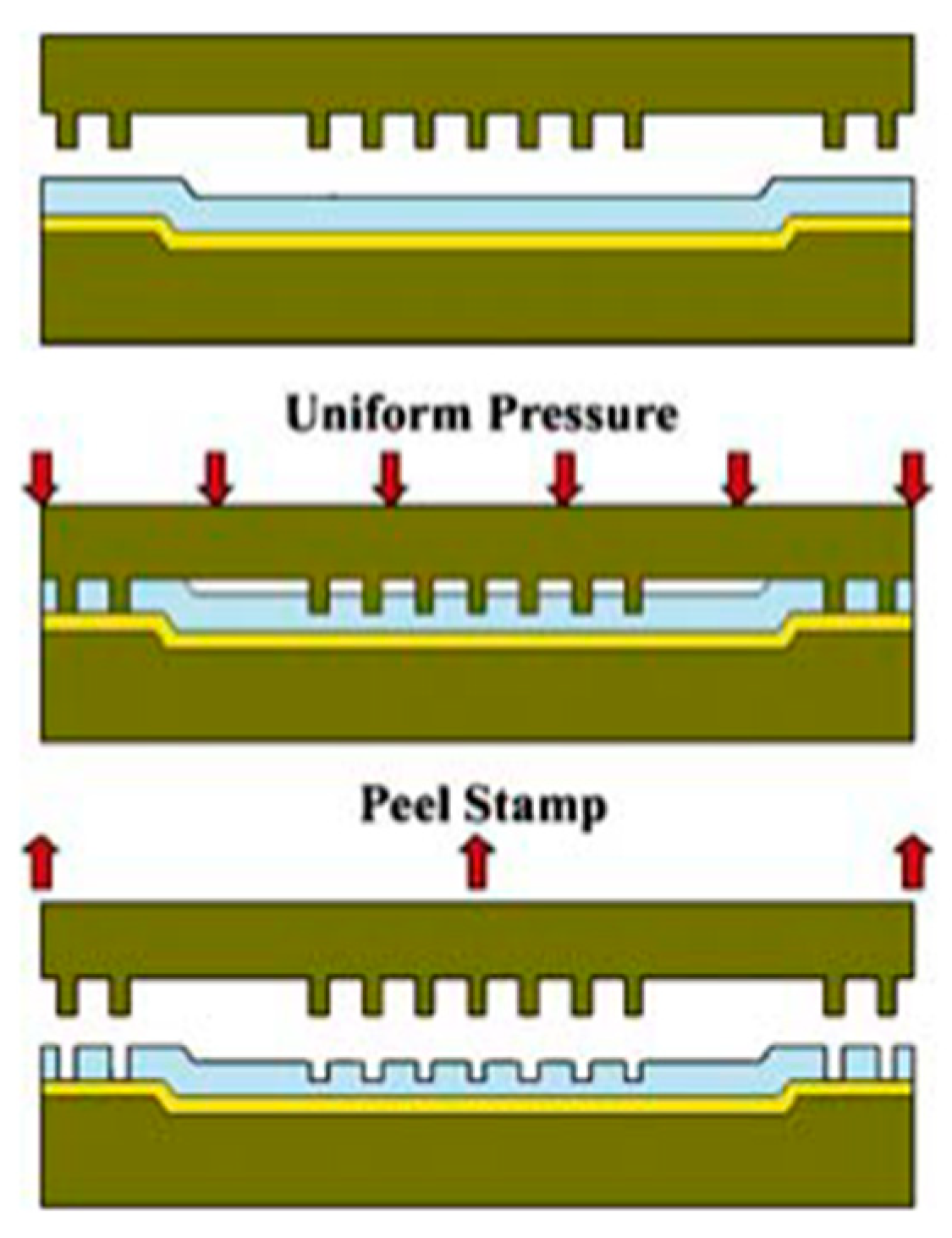
4.3. Imprinting/Soft Molding

A technique of transferring imprinting pattern is called soft molding [35,36]. Figure 20 presents the process of through-hole pattern on a flat PDMS membrane via imprinting/soft molding. Firstly, the PDMS solution was spin-coated to a specific thickness on a substrate with an adhesion reduction layer. Then, a selected mold was carefully placed on the PDMS membrane with an appropriate pressure to displace and penetrate through the uncured PDMS membrane to form the desired patterns. Susquently, the membrane with the mold was fully cured while maintaining the load, hence a desired perforated membrane was sucessfully produced [131]. It is worth mentioning that the volume shrinkage of the photopolymerizable polymer used for imprinting during the photopolymerization was different, resulting in the mold being easily released after imprinting, hence a polymeric membrane with the desired through-holes was obtained [119,136].
The imprinting process consists of pressing a positive pillar mold into a pre-polymer layer coated on a flat surface. Based on the formation process of through-hole PDMS membranes, some researchers reported that the main parameters include the imprinting pressure and the drying method [119,131,136,137]. However, this method is not suitable to produce uniform PDMS nanomembranes over large areas due to increased pre-polymer viscosity, which leads to the difficulty of achieving the required pressure to produce the complete through-holes. Moreover, excessive pressure leads to higher production costs [34].

4.4. Manual Punching

Heo et al. [37] used the method of manual punching to produce through-hole PDMS membranes. They prepared the casting prepolymer (Sylgard 184, Dow-Corning) at a 1:10 curing agent-to-base ratio. The prepolymer was then poured on the positive side of SU-8 (MicroChem) using the backside diffused-light photolithography method to produce the required features. Subsequently, the membrane was cured at 60 °C for 60 min, and the holes were punched in by a sharpened 14-gauge blunt needle.
A manual punching process is merely suitable for low yield patterning PDMS through-hole nanomembranes over small footprints. One reason is the process of punching a needle through a continuous PDMS membrane is time consuming. Another reason is the rather difficult membrane handling at the nanoscale for the punching process [34].

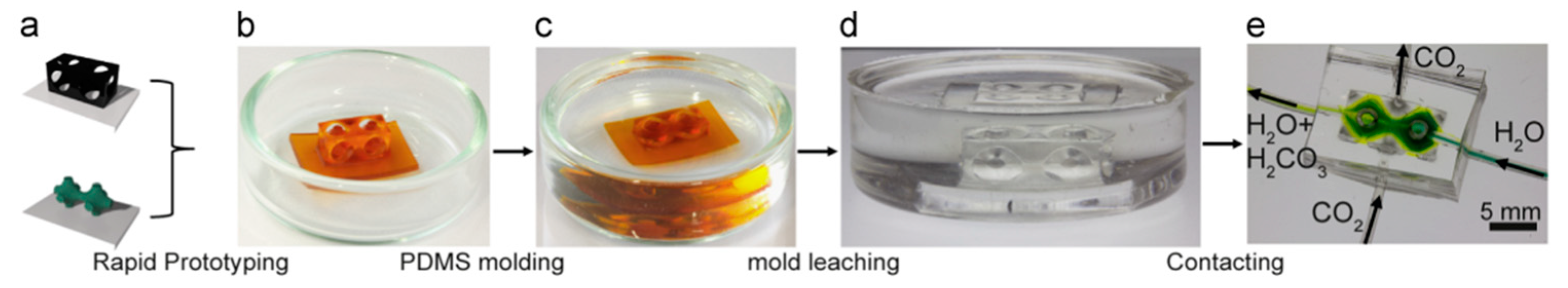
4.5. D Printing Technique

Femmer et al. [38] developed a new sacrificial lithography technique to produce three-dimensional membrane geometries using rapid prototyping (Figure 21). The approach is to print an acrylate-based sacrificial negative mold and use it as a template for the membrane fabrication. Based on “triply periodic minimal surfaces” (TPMS) structures, the molds were designed as Schwarz-D, Schoen-G, and Schoen-P. The molds were then immersed in a PDMS prepolymer formulation (Sylgard 184, silicone/crosslinker 7:1), degassed in vacuum, and subsequently cured at 65 °C for 30 min. Later, the molds were treated with 1 M NaOH at 70 °C. Finally, 1 mm thick micro-structured TPMS-PDMS membranes were obtained, which were thick enough to withstand pressure differences of 2 bar. It was shown that these membranes had 30–60% higher CO2 diffusion coefficients than common hollow-fiber membranes with similar dimensions.
An alternative approach was proposed by printing a PDMS membrane using a direct light processing (DLP) printer to print silicone structures. For optimum compatibilization, the silicone and the photoinitiator were mixed in tetrahydrofuran and then removed in vacuum. The results showed that the printed PDMS membranes had similar selectivity performance as standard PDMS membranes. Conversely, 15% lower permeability than common membranes was related to their larger thickness (840 µm) [39].
Gernally, because of the high cost and the limited hardware available for printing, limited studies have been published on obtaining nanometer resolution in 3D builds to produce perforated PDMS membranes. However, the 3D printing technique could allow an unprecedented control over membrane morphology by allowing both the micro- and the macro-structure of the membrane to be designed and produced in one step, even allowing membrane module fabrication to be controlled in a single machine/process from membrane material to membrane module. Thus, the use of 3D printing in membrane fabrication is a promising method for the near future [138].

5. PP, PI, and PTFE Membranes

5.1. Properties and Applications of PP, PI, and PTFE

Besides PE, PDMS, PSU, and PVDF membranes, numerous studies reported the developments and the applications of other commonly used microporous polymeric membranes such as PP, PI, and PTFE. Table 7 lists the composition and the properties of these polymers.
Microporous polymeric membranes based on PP, PI, and PTFE have been widely used in several fields due to their outstanding properties and low cost. The main areas include both hydrophilic and hydrophobic applications. For hydrophilic applications, water treatment and reuse [143], biochemical and biomedical applications [144,145], battery separators [146,147], and chemical valve applications [148,149,150,151] were developed. However, fouling is the main challenge for hydrophilic microporous polymeric membranes with high performance applications [152], but hydrophilic modification can improve the fouling-resistant properties of polymeric membrane [153]. For hydrophilic applications, membrane distillation and emulsification [154,155,156,157,158] as well as membrane gas absorption [159,160,161] and membrane crystallization [162,163] are available, but other applications such as solvent extraction [164], water-oil separation [165] and vegetable oil membrane filtration [166,167] are investigated. However, it is necessary to prepare super-hydrophobic polymeric membranes with appropriate pore size to deal with the wetting issues and obtain long term performance [153].

5.2. Preparation Methods

To fabricate membranes using PP, PI, and PTFE, the most common methods are TIPS, stretching, electrospinning, NIPS, and a new method that was recently developed, i.e., auxiliary-assisted pore forming. Typical properties of these methods are compared in Table 8. It is important to note that the final polymer membrane morphology and performance are optimized by the combined effects of all the processing parameters.

6. Conclusions and Recommendations

The development of porous polymeric membrane is an important research application in separation technology. This article reviewed the development of porous polymeric membranes from the perspectives of membrane materials and fabrication methods. Polymers such as PE, PDMS, PP, PI, and PTFE were reviewed due to their outstanding thermal stability, chemical resistance, mechanical strength, and low cost. Different fabrication methods such as TIPS, MSCS, PSµM, imprinting/soft molding, manual punching, and three-dimensional printing were also presented and discussed in terms of the strategy to produce porous polymeric membranes with a controlled membrane morphology and performance via key factors associated with each processing method. This included the system, the solution, the processing, and the ambient parameters/conditions. Nevertheless, some challenges still remain, which are subject for future innovation. For example, better materials (properties and stabilities), better fabrication processes (simpler and cost efficient), and applications (new areas) are of interest. Investigations should also aim at improving our understanding of the fouling and the wetting mechanisms, as well as the transport phenomena related to the membrane preparation and use to further accelerate the progress in membrane technology, especially for long term properties.

Author Contributions

Writing—original draft preparation & editing and correction, X.M.T.; supervision & correction, D.R.

Funding

The authors disclosed receipt of the following financial support for the research, authorship, and/or publication of this article: This research was funded by the China Scholarship Council, grant number 201708505089, the Scientific and Technological Research Program of Chongqing Municipal Education Commission, grant number KJ1600631, the Science Foundation for the Excellent Youth Scholars of Chongqing Technology and Business University, grant number 1752007, Open Research Fund of Chongqing Technology and Business University Research Platform, grant number KFJJ2018049 and Scientific Research Foundation for Scholars, Chongqing Technology and Business University, grant number 2016-56-05.

Acknowledgments

The authors would like to thank Sättar Ezzati for his scientific advices and assistance.

Conflicts of Interest

The authors declare no conflict of interest.

Abbreviations

3D3-dimensional
BRbirefringence
CSTcontinuous service temperature
DIDPdiisodecyl phthalate
DINCHdi-isononyl-cyclohexane-1,2-dicarb-oxylate
DLPdirect light processing
DOPdioctyl phthalate
DPEdi-phenylether
EVAethylene vinyl acetate
HDPEhigh density polyethylene
HMBhexamethylbenzene
Jflux
LCSTlower critical solution temperature
LDPElow density polyethylene
L–Lliquid–liquid separation
LLDPElinear low density polyethylene
LPliquid paraffin
MSCSmelt-spinning combined with cold-stretching
NIPSnon-solvent induced phase inversion
OPEoxidized polyethylene
Ppermeability
P’permeance
PDMSpolydimethylsiloxane
PEpolyethylene
PE-b-PEGpolyethylene-block-poly(ethylene glycol)
PIpolyimide
PPpolypropylene
PRphotoresist
PSpolystyrene
PSUpolysulfone
PSµMphase separation micromolding
PTFEpolytetrafluoroethylene
PTMGpolytetramethyleneglycol
PVDFpoly (vinylidene fluoride)
Rtrue retention coefficient
RIEreactive ion etching
Robsobserved retention coefficient
SBOsoybean oil
SEPSpolystyrene-block-poly(ethylene-ran-propylene)-block-polystyrene
S–L or L-Ssolid–liquid separation
T1initial temperature
TCEtrichloroethylene
TEPTEHtriethylolpropanetris (2-ethylhexanoate)
TGglass transition temperature
TIPSthermally induced phase separation
Tmmelting temperature
TPMStriply periodic minimal surfaces
UCSTupper critical solution temperature
UHMWPEultra-high molecular weight polyethylene
V1extrusion speed
V2take-up speed
VIPSvapor-induced phase separation
αselectivity factor
βseparation factor
χinteraction parameter

References

  1. Güell, C.; Ferrando, M.; López, F. Monitoring and Visualizing Membrane-Based Processes; John Wiley & Sons: Hoboken, NJ, USA, 2009. [Google Scholar]
  2. Kanellopoulos, N. Nanoporous Materials: Advanced Techniques for Characterization, Modeling, and Processing; CRC Press: Boca Raton, FL, USA, 2016. [Google Scholar]
  3. Abdelrasoul, A.; Doan, H.; Lohi, A.; Cheng, C.H. Morphology control of polysulfone membranes in filtration processes: A critical review. ChemBioEng Rev. 2015, 2, 22–43. [Google Scholar] [CrossRef]
  4. Lloyd, D.R.; Kim, S.S.; Kinzer, K.E. Microporous membrane formation via thermally-induced phase separation. II. Liquid—Liquid phase separation. J. Membr. Sci. 1991, 64, 1–11. [Google Scholar] [CrossRef]
  5. Lloyd, D.R.; Kinzer, K.E.; Tseng, H. Microporous membrane formation via thermally induced phase separation. I. Solid-liquid phase separation. J. Membr. Sci. 1990, 52, 239–261. [Google Scholar] [CrossRef]
  6. Matsuyama, H.; Okafuji, H.; Maki, T.; Teramoto, M.; Kubota, N. Preparation of polyethylene hollow fiber membrane via thermally induced phase separation. J. Membr. Sci. 2003, 223, 119–126. [Google Scholar] [CrossRef]
  7. Tobo-Niño, O.M.; García-Jiménez, C.D.; Muvdi-Nova, C.J. Flat sheet membrane elaboration by TIPS method using palm oil as solvent and its application in membrane distillation. Ingeniería y Competitividad 2017, 19, 81–90. [Google Scholar]
  8. Vadalia, H.C.; Lee, H.K.; Myerson, A.S.; Levon, K. Thermally induced phase separation in ternary crystallizable polymer solutions. J. Membr. Sci. 1994, 89, 37–50. [Google Scholar] [CrossRef]
  9. Zhang, C.; Bai, Y.; Sun, Y.; Gu, J.; Xu, Y. Preparation of hydrophilic HDPE porous membranes via thermally induced phase separation by blending of amphiphilic PE-b-PEG copolymer. J. Membr. Sci. 2010, 365, 216–224. [Google Scholar] [CrossRef]
  10. Tan, X.M.; Rodrigue, D. A Review on Porous Polymeric Membrane Preparation. Part I: Production Techniques with Polysulfone and Poly (Vinylidene Fluoride). Ploymers 2019, 11, 1160. [Google Scholar] [CrossRef]
  11. Dong, X.; Al-Jumaily, A.; Escobar, I. Investigation of the use of a bio-derived solvent for non-solvent-induced phase separation (NIPS) fabrication of polysulfone membranes. Membranes 2018, 8, 23. [Google Scholar] [CrossRef]
  12. Radovanovic, P.; Thiel, S.W.; Hwang, S.-T. Formation of asymmetric polysulfone membranes by immersion precipitation. Part I. Modelling mass transport during gelation. J. Membr. Sci. 1992, 65, 213–229. [Google Scholar] [CrossRef]
  13. Radovanovic, P.; Thiel, S.W.; Hwang, S.-T. Formation of asymmetric polysulfone membranes by immersion precipitation. Part II. The effects of casting solution and gelation bath compositions on membrane structure and skin formation. J. Membr. Sci. 1992, 65, 231–246. [Google Scholar] [CrossRef]
  14. Ren, J.; Zhou, J.; Deng, M. Morphology transition of asymmetric polyetherimide flat sheet membranes with different thickness by wet phase-inversion process. Sep. Purif. Technol. 2010, 74, 119–129. [Google Scholar] [CrossRef]
  15. Guillen, G.R.; Pan, Y.; Li, M.; Hoek, E.M.V. Preparation and Characterization of Membranes Formed by Nonsolvent Induced Phase Separation: A Review. Ind. Eng. Chem. Res. 2011, 50, 3798–3817. [Google Scholar] [CrossRef]
  16. Park, H.C.; Kim, Y.P.; Kim, H.Y.; Kang, Y.S. Membrane formation by water vapor induced phase inversion. J. Membr. Sci. 1999, 156, 169–178. [Google Scholar] [CrossRef]
  17. Su, Y.; Kuo, C.; Wang, D.; Lai, J.; Deratani, A.; Pochat, C.; Bouyer, D. Interplay of mass transfer, phase separation, and membrane morphology in vapor-induced phase separation. J. Membr. Sci. 2009, 338, 17–28. [Google Scholar] [CrossRef]
  18. Tsai, H.; Kuo, C.; Lin, J.; Wang, D.; Deratani, A.; Pochat-Bohatier, C.; Lee, K.; Lai, J. Morphology control of polysulfone hollow fiber membranes via water vapor induced phase separation. J. Membr. Sci. 2006, 278, 390–400. [Google Scholar] [CrossRef]
  19. Venault, A.; Chang, Y.; Wang, D.-M.; Bouyer, D. A review on polymeric membranes and hydrogels prepared by vapor-induced phase separation process. Polym. Rev. 2013, 53, 568–626. [Google Scholar] [CrossRef]
  20. Kim, J.-J.; Jang, T.-S.; Kwon, Y.-D.; Kim, U.Y.; Kim, S.S. Structural study of microporous polypropylene hollow fiber membranes made by the melt-spinning and cold-stretching method. J. Membr. Sci. 1994, 93, 209–215. [Google Scholar] [CrossRef]
  21. Luo, D.J.; Wei, F.J.; Shao, H.J.; Zhang, K.Z.; Cui, Z.Y.; Yu, J.; Qin, S.H. Effects of Cooling Ways on the Structure of Polypropylene Hollow Fiber Membranes Prepared by Stretching. Int. Polym. Process. 2019, 34, 172–181. [Google Scholar] [CrossRef]
  22. Xi, Z.Y.; Xu, Y.Y.; Zhu, L.P.; Du, C.H.; Zhu, B.K. Effect of stretching on structure and properties of polyethylene hollow fiber membranes made by melt-spinning and stretching process. Polym. Adv. Technol. 2008, 19, 1616–1622. [Google Scholar] [CrossRef]
  23. Bhardwaj, N.; Kundu, S.C. Electrospinning: A fascinating fiber fabrication technique. Biotechnol. Adv. 2010, 28, 325–347. [Google Scholar] [CrossRef]
  24. Huang, L.; Bui, N.N.; Manickam, S.S.; McCutcheon, J.R. Controlling Electrospun Nanofiber Morphology and Mechanical Properties Using Humidity. J. Polym. Sci. Part B-Polym. Phys. 2011, 49, 1734–1744. [Google Scholar] [CrossRef]
  25. Raghavan, P.; Lim, D.-H.; Ahn, J.-H.; Nah, C.; Sherrington, D.C.; Ryu, H.-S.; Ahn, H.-J. Electrospun polymer nanofibers: The booming cutting edge technology. React. Funct. Polym. 2012, 72, 915–930. [Google Scholar] [CrossRef] [Green Version]
  26. Yao, Y.; Zhu, P.; Ye, H.; Niu, A.; Gao, X.; Wu, D. Polysulfone nanofibers prepared by electrospinning and gas/jet-electrospinning. Front. Chem. China 2006, 1, 334–339. [Google Scholar] [CrossRef]
  27. Apel, P. Track etching technique in membrane technology. Radiat. Meas. 2001, 34, 559–566. [Google Scholar] [CrossRef]
  28. Daubresse, C.; Sergent-Engelen, T.; Ferain, E.; Schneider, Y.J.; Legras, R. Characterisation of energetic heavy ion track in PVDF: Production of PVDF track-etched membrane and application. Nucl. Instrum. Methods Phys. Res. Sect. B Beam Interact. Mater. Atoms 1995, 105, 126–129. [Google Scholar] [CrossRef]
  29. Grasselli, M.; Betz, N. Making porous membranes by chemical etching of heavy-ion tracks in β-PVDF films. Nucl. Inst. Methods Phys. Res. B 2005, 236, 501–507. [Google Scholar] [CrossRef]
  30. Guo, J.; Berbano, S.S.; Guo, H.; Baker, A.L.; Lanagan, M.T.; Randall, C.A. Cold Sintering Process of Composites: Bridging the Processing Temperature Gap of Ceramic and Polymer Materials. Adv. Funct. Mater. 2016, 26, 7115–7121. [Google Scholar] [CrossRef]
  31. Jon-Paul, M.; Kang, X.; Floyd, R.; Dickey, E.; Guo, H.; Guo, J.; Baker, A.; Funihashi, S.; Randall, C. Cold sintering: Current status and prospects. J. Mater. Res. 2017, 32, 3205–3218. [Google Scholar] [CrossRef] [Green Version]
  32. Jo, B.H.; Van Lerberghe, L.M.; Motsegood, K.M.; Beebe, D.J. Three-dimensional micro-channel fabrication in polydimethylsiloxane (PDMS) elastomer. J. Microelectromech. Syst. 2000, 9, 76–81. [Google Scholar] [CrossRef]
  33. Luo, Y.; Zare, R.N. Perforated membrane method for fabricating three-dimensional polydimethylsiloxane microfluidic devices. Lab Chip 2008, 8, 1688–1694. [Google Scholar] [CrossRef]
  34. Tibbe, M.; Loessberg-Zahl, J.; Do Carmo, M.P.; Van Der Helm, M.; Bomer, J.; Van Den Berg, A.; Leferink, A.; Segerink, L.; Eijkel, J. Large-scale fabrication of free-standing and sub-μm PDMS through-hole membranes. Nanoscale 2018, 10, 7711–7718. [Google Scholar]
  35. Kim, Y.S.; Suh, K.Y.; Lee, H.H. Fabrication of three-dimensional microstructures by soft molding. Appl. Phys. Lett. 2001, 79, 2285–2287. [Google Scholar] [CrossRef] [Green Version]
  36. Thangawng, A.L.; Lee, J. Fabrication of a Micro/Nano Integrated Roughened Structure using Nanosphere Lithography (NSL). In Proceedings of the ASME 2004 International Mechanical Engineering Congress and Exposition, Anaheim, CA, USA, 13–19 November 2004; pp. 463–468. [Google Scholar]
  37. Heo, Y.S.; Cabrera, L.M.; Song, J.W.; Futai, N.; Tung, Y.-C.; Smith, G.D.; Takayama, S. Characterization and resolution of evaporation-mediated osmolality shifts that constrain microfluidic cell culture in poly(dimethylsiloxane) devices. Anal. Chem. 2007, 79, 1126. [Google Scholar] [CrossRef]
  38. Femmer, T.; Kuehne, A.J.C.; Torres-Rendon, J.; Walther, A.; Wessling, M. Print your membrane: Rapid prototyping of complex 3D-PDMS membranes via a sacrificial resist. J. Membr. Sci. 2015, 478, 12–18. [Google Scholar] [CrossRef]
  39. Femmer, T.; Kuehne, A.J.C.; Wessling, M. Print your own membrane: Direct rapid prototyping of polydimethylsiloxane. Lab Chip 2014, 14, 2610–2613. [Google Scholar] [CrossRef]
  40. Warsinger, D.M.; Chakraborty, S.; Tow, E.W.; Plumlee, M.H.; Bellona, C.; Loutatidou, S.; Karimi, L.; Mikelonis, A.M.; Achilli, A.; Ghassemi, A. A review of polymeric membranes and processes for potable water reuse. Progress Polym. Sci. 2018, 81, 209–237. [Google Scholar] [CrossRef]
  41. Peter-Varbanets, M.; Zurbrügg, C.; Swartz, C.; Pronk, W. Decentralized systems for potable water and the potential of membrane technology. Water Res. 2009, 43, 245–265. [Google Scholar] [CrossRef]
  42. Pendergast, M.M.; Hoek, E.M. A review of water treatment membrane nanotechnologies. Energy Environ. Sci. 2011, 4, 1946–1971. [Google Scholar] [CrossRef] [Green Version]
  43. Ulbricht, M. Advanced functional polymer membranes. Polymer 2006, 47, 2217–2262. [Google Scholar] [CrossRef] [Green Version]
  44. Kesting, R.E. The four tiers of structure in integrally skinned phase inversion membranes and their relevance to the various separation regimes. J. Appl. Polym. Sci. 1990, 41, 2739–2752. [Google Scholar] [CrossRef]
  45. Ong, Y.K.; Shi, G.M.; Le, N.L.; Tang, Y.P.; Zuo, J.; Nunes, S.P.; Chung, T.-S. Recent membrane development for pervaporation processes. Progress Polym. Sci. 2016, 57, 1–31. [Google Scholar] [CrossRef] [Green Version]
  46. Zwolinski, B.J.; Eyring, H.; Reese, C.E. Diffusion and Membrane Permeability. J. Phys. Colloid Chem. 1949, 53, 1426–1453. [Google Scholar] [CrossRef]
  47. Platt, S.; Mauramo, M.; Butylina, S.; Nyström, M. Retention of pegs in cross-flow ultrafiltration through membranes. Desalination 2002, 149, 417–422. [Google Scholar] [CrossRef]
  48. Ochoa, N.A.; Prádanos, P.; Palacio, L.; Pagliero, C.; Marchese, J.; Hernández, A. Pore size distributions based on AFM imaging and retention of multidisperse polymer solutes: Characterisation of polyethersulfone UF membranes with dopes containing different PVP. J. Membr. Sci. 2001, 187, 227–237. [Google Scholar] [CrossRef]
  49. Bae, B.; Chun, B.H.; Kim, D. Surface characterization of microporous polypropylene membranes modified by plasma treatment. Polymer 2001, 42, 7879–7885. [Google Scholar] [CrossRef]
  50. Croce, F.; Appetecchi, G.B.; Persi, L.; Scrosati, B. Nanocomposite polymer electrolytes for lithium batteries. Nature 1998, 394, 456. [Google Scholar] [CrossRef]
  51. Mulder, J. Basic Principles of Membrane Technology; Springer Science & Business Media: Berlin/Heidelberg, Germany, 2012. [Google Scholar]
  52. Park, M.J.; Kim, C. Fabrication of polyethylene microporous membranes using triethylolpropane tris (2-ethylhexanoate) as a novel diluent by a thermally induced phase separation process. J. Membr. Sci. 2014, 449, 127–135. [Google Scholar] [CrossRef]
  53. Baker, R.W.; Cussler, E.L.; Eykamp, W.; Koros, W.J.; Riley, R.L.; Strathmann, H. Membrane Separation System: Recent Developments Future Directions; Noyes Publications: Park Ridge, NJ, USA, 1991; pp. 100–150. [Google Scholar]
  54. Roh, S.C.; Song, K.W.; Kim, C. Effects of nonsolvent molecular structure and its content on the formation of the macroporous polyarylate layer coated onto the polyethylene separator. Ind. Eng. Chem. Res. 2011, 50, 12596–12605. [Google Scholar] [CrossRef]
  55. Jeon, M.Y.; Kim, C.K. Phase behavior of polymer/diluent/diluent mixtures and their application to control microporous membrane structure. J. Membr. Sci. 2007, 300, 172–181. [Google Scholar] [CrossRef]
  56. Kim, W.K.; Char, K.; Kim, C.K. Control of droplet size of polymer–diluent blends through thermally induced phase separation. J. Polym. Sci. B Polym. Phys. 2000, 38, 3042–3052. [Google Scholar] [CrossRef]
  57. Liu, S.; Zhou, C.; Yu, W. Phase separation and structure control in ultra-high molecular weight polyethylene microporous membrane. J. Membr. Sci. 2011, 379, 268–278. [Google Scholar] [CrossRef]
  58. Matsuyama, H.; Kudari, S.; Kiyofuji, H.; Kitamura, Y. Kinetic studies of thermally induced phase separation in polymer–diluent system. J. Appl. Polym. Sci. 2000, 76, 1028–1036. [Google Scholar] [CrossRef]
  59. Roh, S.; Park, M.; Yoo, S.; Kim, C. Changes in microporous structure of polyethylene membrane fabricated from PE/PTMG/paraffin ternary mixtures. J. Membr. Sci. 2012, 411, 201–210. [Google Scholar] [CrossRef]
  60. Shang, M.; Matsuyama, H.; Teramoto, M.; Okuno, J.; Lloyd, D.R.; Kubota, N. Effect of diluent on poly(ethylene-co-vinyl alcohol) hollow-fiber membrane formation via thermally induced phase separation. J. Appl. Polym. Sci. 2005, 95, 219–225. [Google Scholar] [CrossRef]
  61. Matsuyama, H.; Yuasa, M.; Kitamura, Y.; Teramoto, M.; Lloyd, D.R. Structure control of anisotropic and asymmetric polypropylene membrane prepared by thermally induced phase separation. J. Membr. Sci. 2000, 179, 91–100. [Google Scholar] [CrossRef]
  62. Matsuyama, H.; Maki, T.; Teramoto, M.; Asano, K. Effect of polypropylene molecular weight on porous membrane formation by thermally induced phase separation. J. Membr. Sci. 2002, 204, 323–328. [Google Scholar] [CrossRef]
  63. Kim, J.F.; Kim, J.H.; Lee, Y.M.; Drioli, E. Thermally induced phase separation and electrospinning methods for emerging membrane applications: A review. Adv. Mater. Sep. Mater. Devices Process. 2016, 62, 461–490. [Google Scholar] [CrossRef]
  64. Liu, F.; Hashim, N.A.; Liu, Y.; Abed, M.R.M.; Li, K. Progress in the production and modification of PVDF membranes. J. Membr. Sci. 2011, 375, 1–27. [Google Scholar] [CrossRef]
  65. Kim, S.S.; Lloyd, D.R. Microporous membrane formation via thermally-induced phase separation. III. Effect of thermodynamic interactions on the structure of isotactic polypropylene membranes. J. Membr. Sci. 1991, 64, 13–29. [Google Scholar] [CrossRef]
  66. Matsuyama, H.; Berghmans, S.; Lloyd, D.R. Formation of hydrophilic microporous membranes via thermally induced phase separation. J. Membr. Sci. 1998, 142, 213–224. [Google Scholar] [CrossRef]
  67. Van Krevelen, D. Crystallinity of polymers and means to influence crystallization process. Chimia 1978, 32, 279–294. [Google Scholar]
  68. Keith, H.; Padden, F. Spherulitic crystallization from the melt. I. Fractionation and impurity segregation and their influence on crystalline morphology. J. Appl. Phys. 1964, 35, 1270–1285. [Google Scholar] [CrossRef]
  69. Chiang, C.-Y. Poly(phenylene Sulfide)(pps) Membrane Formation via Solid-Liquid Thermally Induced Phase Separation. Ph.D. Thesis, The University of Texas at Austin, Austin, TX, USA, 1995. [Google Scholar]
  70. Laxminarayan, A. The Kinetics of Membrane Formation via Thermally Induced Liquid-Liquid Phase Separation. Ph.D. Thesis, The University of Texas at Austin, Austin, TX, USA, 1996. [Google Scholar]
  71. Laxminarayan, A.; McGuire, K.S.; Kim, S.S.; Lloyd, D.R. Effect of initial composition, phase separation temperature and polymer crystallization on the formation of microcellular structures via thermally induced phase separation. Polymer 1994, 35, 3060–3068. [Google Scholar] [CrossRef]
  72. McGuire, K.S. Membrane Formation via Liquid-Liquid Thermally Induced Phase Separation. Ph.D. Thesis, The University of Texas at Austin, Austin, TX, USA, 1995. [Google Scholar]
  73. McGuire, K.S.; Laxminarayan, A.; Martula, D.S.; Lloyd, D.R. Kinetics of droplet growth in liquid–liquid phase separation of polymer–diluent systems: Model development. J. Colloid Interface Sci. 1996, 182, 46–58. [Google Scholar] [CrossRef]
  74. Chiang, C.-Y.; Starov, V.; Lloyd, D. Crystallization kinetics of a polymer-solvent system. I: Derivation of model equations. Colloid J. Russ. Acad. Sci. 1995, 57, 715–724. [Google Scholar]
  75. Ji, G.-L.; Du, C.-H.; Zhu, B.-K.; Xu, Y.-Y. Preparation of porous PVDF membrane via thermally induced phase separation with diluent mixture of DBP and DEHP. J. Appl. Polym. Sci. 2007, 105, 1496–1502. [Google Scholar] [CrossRef]
  76. Hassankiadeh, N.T.; Cui, Z.; Kim, J.H.; Shin, D.W.; Sanguineti, A.; Arcella, V.; Lee, Y.M.; Drioli, E. PVDF hollow fiber membranes prepared from green diluent via thermally induced phase separation: Effect of PVDF molecular weight. J. Membr. Sci. 2014, 471, 237–246. [Google Scholar] [CrossRef]
  77. Gu, M.; Zhang, J.; Xia, Y.; Wang, X. Poly(vinylidene fluoride) crystallization behavior and membrane structure formation via thermally induced phase separation with benzophenone diluent. J. Macromol. Sci. Part B 2007, 47, 180–191. [Google Scholar] [CrossRef]
  78. Ghasem, N.; Al-Marzouqi, M.; Duaidar, A. Effect of quenching temperature on the performance of poly(vinylidene fluoride) microporous hollow fiber membranes fabricated via thermally induced phase separation technique on the removal of CO2 from CO2-gas mixture. Int. J. Greenh. Gas Control 2011, 5, 1550–1558. [Google Scholar] [CrossRef]
  79. Yang, J.; Li, D.W.; Lin, Y.K.; Wang, X.L.; Tian, F.; Wang, Z. Formation of a bicontinuous structure membrane of polyvinylidene fluoride in diphenyl ketone diluent via thermally induced phase separation. J. Appl. Polym. Sci. 2008, 110, 341–347. [Google Scholar] [CrossRef]
  80. Burghardt, W. Phase diagrams for binary polymer systems exhibiting both crystallization and limited liquid-liquid miscibility. Macromolecules 1989, 22, 2482–2486. [Google Scholar] [CrossRef]
  81. Castro, A.J. Methods for Making Microporous Products. U.S. Patent 4247498A, 27 January 1981. [Google Scholar]
  82. Shipman, G.H. Microporous Sheet Material, Method of Making and Articles Made Therewith. U.S. Patent 4539256A, 3 September 1985. [Google Scholar]
  83. Caneba, G.T.; Soong, D.S. Polymer membrane formation through the thermal-inversion process. 1. Experimental study of membrane structure formation. Macromolecules 1985, 18, 2538–2545. [Google Scholar] [CrossRef]
  84. Caneba, G.T.; Soong, D.S. Polymer membrane formation through the thermal-inversion process. 2. Mathematical modeling of membrane structure formation. Macromolecules 1985, 18, 2545–2555. [Google Scholar] [CrossRef]
  85. Tsai, F.J.; Torkelson, J.M. The roles of phase separation mechanism and coarsening in the formation of poly (methyl methacrylate) asymmetric membranes. Macromolecules 1990, 23, 775–784. [Google Scholar] [CrossRef]
  86. Hassankiadeh, N.T.; Cui, Z.; Kim, J.H.; Shin, D.W.; Lee, S.Y.; Sanguineti, A.; Arcella, V.; Lee, Y.M.; Drioli, E. Microporous poly(vinylidene fluoride) hollow fiber membranes fabricated with PolarClean as water-soluble green diluent and additives. J. Membr. Sci. 2015, 479, 204–212. [Google Scholar] [CrossRef]
  87. Cui, Z.; Hassankiadeh, N.T.; Lee, S.Y.; Woo, K.T.; Lee, J.M.; Sanguineti, A.; Arcella, V.; Lee, Y.M.; Drioli, E. Tailoring novel fibrillar morphologies in poly(vinylidene fluoride) membranes using a low toxic triethylene glycol diacetate (TEGDA) diluent. J. Membr. Sci. 2015, 473, 128–136. [Google Scholar] [CrossRef]
  88. Kim, L.U.; Kim, C.K. A novel method for the pore size control of the battery separator using the phase instability of the ternary mixtures. J. Polym. Sci. Part B Polym. Phys. 2006, 44, 2025–2034. [Google Scholar] [CrossRef]
  89. Matsuyama, H.; Kim, M.-M.; Lloyd, D.R. Effect of extraction and drying on the structure of microporous polyethylene membranes prepared via thermally induced phase separation. J. Membr. Sci. 2002, 204, 413–419. [Google Scholar] [CrossRef]
  90. Yoon, J.; Lesser, A.J.; McCarthy, T.J. Locally anisotropic porous materials from polyethylene and crystallizable diluents. Macromolecules 2009, 42, 8827–8834. [Google Scholar] [CrossRef]
  91. Hemmati, F.; Garmabi, H.; Modarress, H. Phase behavior of polyethylene/ethylene vinyl acetate blends: Studies on miscibility window, composition dependency of interfacial interactions, and enhanced toughness. J. Plast. Film Sheeting 2015, 31, 8–26. [Google Scholar] [CrossRef]
  92. Dhibar, A.K.; Kim, J.K.; Khatua, B.B. Cocontinuous phase morphology of asymmetric compositions of polypropylene/high-density polyethylene blend by the addition of clay. J. Appl. Polym. Sci. 2011, 119, 3080–3092. [Google Scholar] [CrossRef]
  93. Iqbal, M.Z.; Abdala, A.A.; Liberatore, M.W. Synthesis and characterization of polyethylene/oxidized polyethylene miscible blends and role of OPE as a viscosity control. Appl. Polym. 2016, 133. [Google Scholar] [CrossRef]
  94. Lloyd, D.R.; Lim, G.B. Microporous membrane formation via thermally-induced phase separation. VII. Effect of dilution, cooling rate, and nucleating agent addition on morphology. J. Membr. Sci. 1993, 79, 27–34. [Google Scholar]
  95. Cha, B.J.; Char, K.; Kim, J.J.; Kim, S.S.; Kim, C.K. The effects of diluent molecular weight on the structure of thermally-induced phase separation membrane. J. Membr. Sci. 1995, 108, 219–229. [Google Scholar] [CrossRef]
  96. Kamada, K.; Minami, S.; Yoshida, K. Porous Polypropylene Hollow Filaments and Method Making the Same. U.S. Patent 4055696A, 25 October 1977. [Google Scholar]
  97. Druin, M.L.; Loft, J.T.; Plovan, S.G. Novel Open-Celled Microporous Film. U.S. Patent 3679538A, 25 July 1972. [Google Scholar]
  98. Yoshida, K. Structural feature and membrane properties of microporous hollow fibers. Kobunshi 1988, 37, 142–151. [Google Scholar] [CrossRef]
  99. Lee, S.-Y.; Park, S.-Y.; Song, H.-S. Lamellar crystalline structure of hard elastic HDPE films and its influence on microporous membrane formation. Polymer 2006, 47, 3540–3547. [Google Scholar] [CrossRef]
  100. Keller, A.; Machin, M.J. Oriented crystallization in polymers. J. Macromol. Sci. Part B 1967, 1, 41–91. [Google Scholar] [CrossRef]
  101. Bierenbaum, H.S.; Isaacson, R.B.; Druin, M.L.; Plovan, S.G. Microporous polymeric films. Ind. Eng. Chem. Prod. Res. Dev. 1974, 13, 2–9. [Google Scholar] [CrossRef]
  102. Shen, L.-Q.; Xu, Z.-K.; Xu, Y.-Y. Preparation and characterization of microporous polyethylene hollow fiber membranes. J. Appl. Polym. Sci. 2002, 84, 203–210. [Google Scholar] [CrossRef]
  103. Ding, Z.; Bao, R.; Zhao, B.; Yan, J.; Liu, Z.; Yang, M. Effects of annealing on structure and deformation mechanism of isotactic polypropylene film with row-nucleated lamellar structure. J. Appl. Polym. Sci. 2013, 130, 1659–1666. [Google Scholar] [CrossRef]
  104. Sahraeian, R.; Davachi, S.M.; Heidari, B.S. The effect of nanoperlite and its silane treatment on thermal properties and degradation of polypropylene/nanoperlite nanocomposite films. Compos. Part B Eng. 2019, 162, 103–111. [Google Scholar] [CrossRef]
  105. Ferrer-Balas, D.; Maspoch, M.L.; Martinez, A.; Santana, O. Influence of annealing on the microstructural, tensile and fracture properties of polypropylene films. Polymer 2001, 42, 1697–1705. [Google Scholar] [CrossRef]
  106. Gu, F.; Bu, H.; Zhang, Z. New Observations on the Formation of “Row-Nucleated” Structures of Isotactic Polystyrene. Macromolecules 2000, 33, 5490–5494. [Google Scholar] [CrossRef]
  107. Elyashevich, G.; Sazanov, Y.N.; Rozova, E.Y.; Lavrentyev, V.; Kuryndin, I.; Praslova, O.; Fedorova, G. Thermal stability of polyethylene microporous films with a poly (pyrrole) conducting layer. Polym. Sci. Ser. AC/C Vysokomol. Soedin. 2001, 43, 970–975. [Google Scholar]
  108. Hoffman, J.; Davis, G.T.; Lauritzen, J. Treatise on Solid State Chemistry; Plenum Press: New York, NY, USA, 1976; Volume 3, p. 497. [Google Scholar]
  109. Zhang, M.; Zhang, C.-F.; Yao, Z.-K.; Shi, J.-L.; Zhu, B.-K.; Xu, Y.-Y. Preparation of high density polyethylene/polyethylene-block-poly (ethylene glycol) copolymer blend porous membranes via thermally induced phase separation process and their properties. Chin. J. Polym. Sci. 2010, 28, 337–346. [Google Scholar] [CrossRef]
  110. Chen, R.; Saw, C.; Jamieson, M.; Aversa, T.; Callahan, R. Structural characterization of Celgard® microporous membrane precursors: Melt-extruded polyethylene films. J. Appl. Polym. Sci. 1994, 53, 471–483. [Google Scholar] [CrossRef]
  111. Elyashevich, G.K.; Karpov, E.; Rosova, E.Y.; Streltses, B.V.; Marikhin, V.A.; Myasnikova, L.P. Orientational crystallization and orientational drawing as strengthening methods for polyethylene. Polym. Eng. Sci. 1993, 33, 1341–1351. [Google Scholar] [CrossRef]
  112. Takemura, D.; Aihara, S.; Hamano, K.; Kise, M.; Nishimura, T.; Urushibata, H.; Yoshiyasu, H. A powder particle size effect on ceramic powder based separator for lithium rechargeable battery. J. Power Sources 2005, 146, 779–783. [Google Scholar] [CrossRef]
  113. Wool, R.P. Morphological mechanics of springy polymers. J. Polym. Sci. Polym. Phys. Ed. 1976, 14, 603–618. [Google Scholar] [CrossRef]
  114. Samuels, R.J. High strength elastic polypropylene. J. Polym. Sci. Polym. Phys. Ed. 1979, 17, 535–568. [Google Scholar] [CrossRef]
  115. Seethapathy, S.; Górecki, T. Applications of polydimethylsiloxane in analytical chemistry: A review. Anal. Chim. Acta 2012, 750, 48–62. [Google Scholar] [CrossRef]
  116. Kim, H.J.; Huh, D.; Hamilton, G.; Ingber, D.E. Human gut-on-a-chip inhabited by microbial flora that experiences intestinal peristalsis-like motions and flow. Lab Chip 2012, 12, 2165–2174. [Google Scholar] [CrossRef]
  117. Huh, D.; Kim, H.J.; Fraser, J.P.; Shea, D.E.; Khan, M.; Bahinski, A.; Hamilton, G.A.; Ingber, D.E. Microfabrication of human organs-on-chips. Nat. Protoc. 2013, 8, 2135. [Google Scholar] [CrossRef]
  118. van der Helm, M.W.; Odijk, M.; Frimat, J.-P.; van der Meer, A.D.; Eijkel, J.C.T.; van den Berg, A.; Segerink, L.I. Direct quantification of transendothelial electrical resistance in organs-on-chips. Biosens. Bioelectron. 2016, 85, 924–929. [Google Scholar] [CrossRef] [Green Version]
  119. Yanagishita, T.; Nishio, K.; Masuda, H. Polymer through-hole membrane fabricated by nanoimprinting using metal molds with high aspect ratios. J. Vac. Sci. Technol. B 2007, 25, L35–L38. [Google Scholar] [CrossRef]
  120. Mosadegh, B.; Agarwal, M.; Torisawa, Y.-S.; Takayama, S. Simultaneous fabrication of PDMS through-holes for three-dimensional microfluidic applications. Lab Chip 2010, 10, 1983. [Google Scholar] [CrossRef]
  121. Izuka, A.; Winter, H.H.; Hashimoto, T. Molecular weight dependence of viscoelasticity of polycaprolactone critical gels. Macromolecules 1992, 25, 2422–2428. [Google Scholar] [CrossRef]
  122. Zhao, Y.; Zhang, X. Mechanical Properties Evolution of Polydimethylsiloxane During Crosslinking Process. MRS Proc. 2006, 975, 0975-DD0906-0907. [Google Scholar] [CrossRef]
  123. Hanson, D.E. An explicit polymer and node network model to compute micromechanical properties of silica-filled polydimethylsiloxane. Polymer 2004, 45, 1055–1062. [Google Scholar] [CrossRef]
  124. Dittrich, P.S.; Manz, A. Lab-on-a-chip: Microfluidics in drug discovery. Nat. Rev. Drug Discov. 2006, 5, 210. [Google Scholar] [CrossRef]
  125. Wei, H.; Chueh, B.-H.; Wu, H.; Hall, E.W.; Li, C.-W.; Schirhagl, R.; Lin, J.-M.; Zare, R.N. Particle sorting using a porous membrane in a microfluidic device. Lab Chip 2011, 11, 238–245. [Google Scholar] [CrossRef]
  126. Vogelaar, L.; Barsema, J.N.; Van Rijn, C.J.M.; Nijdam, W.; Wessling, M. Phase Separation Micromolding—PSμM. Adv. Mater. 2003, 15, 1385–1389. [Google Scholar] [CrossRef]
  127. Neklyudova, M.; Erdamar, A.K.; Vicarelli, L.; Heerema, S.J.; Rehfeldt, T.; Pandraud, G.; Kolahdouz, Z.; Dekker, C.; Zandbergen, H.W. Through-membrane electron-beam lithography for ultrathin membrane applications. Appl. Phys. Lett. 2017, 111. [Google Scholar] [CrossRef]
  128. Neils, C.; Tyree, Z.; Finlayson, B.; Folch, A. Combinatorial mixing of microfluidic streams. Lab Chip 2004, 4, 342–350. [Google Scholar] [CrossRef]
  129. Li, J.; Stein, D.; McMullan, C.; Branton, D.; Aziz, M.J.; Golovchenko, J.A. Ion-beam sculpting at nanometre length scales. Nature 2001, 412, 166–169. [Google Scholar] [CrossRef] [Green Version]
  130. Firpo, G.; Angeli, E.; Repetto, L.; Valbusa, U. Permeability thickness dependence of polydimethylsiloxane (PDMS) membranes. J. Membr. Sci. 2015, 481, 1–8. [Google Scholar] [CrossRef] [Green Version]
  131. Thangawng, A.; Ruoff, R.; Swartz, M.; Glucksberg, M. An ultra-thin PDMS membrane as a bio/micro–nano interface: Fabrication and characterization. Biomed. Microdevices 2007, 9, 587–595. [Google Scholar] [CrossRef]
  132. Lötters, J.C. The mechanical properties of the rubber elastic polymer polydimethylsiloxane for sensor applications. J. Micromech. Microeng. 1997, 7, 145–147. [Google Scholar] [CrossRef]
  133. Tahk, D.; Paik, S.-M.; Lim, J.; Bang, S.; Oh, S.; Ryu, H.; Jeon, N.L. Rapid large area fabrication of multiscale through-hole membranes. Lab Chip 2017, 17, 1817–1825. [Google Scholar] [CrossRef]
  134. Atsuta, K.; Noji, H.; Takeuchi, S. Micro patterning of active proteins with perforated PDMS sheets (PDMS sieve). Lab Chip 2004, 4, 333–336. [Google Scholar] [CrossRef]
  135. Kang, J.H.; Um, E.; Park, J.-K. Fabrication of a poly(dimethylsiloxane) membrane with well-defined through-holes for three-dimensional microfluidic networks. J. Micromech. Microeng. 2009, 19, 045027. [Google Scholar] [CrossRef]
  136. Yanagishita, T.; Nishio, K.; Masuda, H. Antireflection Polymer Hole Array Structures by Imprinting Using Metal Molds from Anodic Porous Alumina. Appl. Phys. Express 2008, 1, 067004. [Google Scholar] [CrossRef]
  137. Grimm, S.; Lange, A.; Enke, D.; Steinhart, M. Imprinting macropore arrays into mesoporous silica monoliths. J. Mater. Chem. 2012, 22, 9490–9493. [Google Scholar] [CrossRef]
  138. Low, Z.-X.; Chua, Y.T.; Ray, B.M.; Mattia, D.; Metcalfe, I.S.; Patterson, D.A. Perspective on 3D printing of separation membranes and comparison to related unconventional fabrication techniques. J. Membr. Sci. 2017, 523, 596–613. [Google Scholar] [CrossRef] [Green Version]
  139. Mark, J.E. Physical Properties of Polymers Handbook; Springer: Berlin/Heidelberg, Germany, 2007; Volume 1076. [Google Scholar]
  140. Luo, B.; Li, Z.; Zhang, J.; Wang, X. Formation of anisotropic microporous isotactic polypropylene (iPP) membrane via thermally induced phase separation. Desalination 2008, 233, 19–31. [Google Scholar] [CrossRef]
  141. Vanherck, K.; Koeckelberghs, G.; Vankelecom, I.F.J. Crosslinking polyimides for membrane applications: A review. Progress Polym. Sci. 2012, 38. [Google Scholar] [CrossRef]
  142. Feng, S.; Zhong, Z.; Wang, Y.; Xing, W.; Drioli, E. Progress and perspectives in PTFE membrane: Preparation, modification, and applications. J. Membr. Sci. 2018, 549, 332–349. [Google Scholar] [CrossRef]
  143. Yin, J.; Deng, B. Polymer-matrix nanocomposite membranes for water treatment. J. Membr. Sci. 2015, 479, 256–275. [Google Scholar] [CrossRef]
  144. Yang, Q.; Xu, Z.-K.; Dai, Z.-W.; Wang, J.-L.; Ulbricht, M. Surface Modification of Polypropylene Microporous Membranes with a Novel Glycopolymer. Chem. Mater. 2005, 17, 3050–3058. [Google Scholar] [CrossRef]
  145. Wang, Y.J.; Chen, C.H.; Yeh, M.L.; Hsiue, G.H.; Yu, B.C. A one-side hydrophilic polypropylene membrane prepared by plasma treatment. J. Membr. Sci. 1990, 53, 275–286. [Google Scholar] [CrossRef]
  146. Arora, P.; Zhang, Z. Battery Separators. Chem. Rev. 2004, 104, 4419–4462. [Google Scholar] [CrossRef]
  147. Ciszewski, A.; Rydzyńska, B. Studies on self-assembly phenomena of hydrophilization of microporous polypropylene membrane by acetone aldol condensation products: New separator for high-power alkaline batteries. J. Power Sources 2007, 166, 526–530. [Google Scholar] [CrossRef]
  148. Liang, L.; Shi, M.; Viswanathan, V.V.; Peurrung, L.M.; Young, J.S. Temperature-sensitive polypropylene membranes prepared by plasma polymerization. J. Membr. Sci. 2000, 177, 97–108. [Google Scholar] [CrossRef]
  149. Wan, L.-S.; Yang, Y.-F.; Tian, J.; Hu, M.-X.; Xu, Z.-K. Construction of comb-like poly(N-isopropylacrylamide) layers on microporous polypropylene membrane by surface-initiated atom transfer radical polymerization. J. Membr. Sci. 2009, 327, 174–181. [Google Scholar] [CrossRef]
  150. Guo, H.; Ulbricht, M. Preparation of thermo-responsive polypropylene membranes via surface entrapment of poly(N-isopropylacrylamide)-containing macromolecules. J. Membr. Sci. 2011, 372, 331–339. [Google Scholar] [CrossRef]
  151. Yu, H.-Y.; Li, W.; Zhou, J.; Gu, J.-S.; Huang, L.; Tang, Z.-Q.; Wei, X.-W. Thermo- and pH-responsive polypropylene microporous membrane prepared by the photoinduced RAFT-mediated graft copolymerization. J. Membr. Sci. 2009, 343, 82–89. [Google Scholar] [CrossRef]
  152. McDonogh, R.M.; Bauser, H.; Stroh, N.; Chmiel, H. Concentration polarisation and adsorption effects in cross-flow ultrafiltration of proteins. Desalination 1990, 79, 217–231. [Google Scholar] [CrossRef]
  153. Himma, N.; Anisah, S.; Prasetya, N.; Wenten, I. Advances in preparation, modification, and application of polypropylene membrane. J. Polym. Eng. 2016, 36, 329–362. [Google Scholar] [CrossRef]
  154. Gryta, M. Wettability of polypropylene capillary membranes during the membrane distillation process. Chem. Pap. 2012, 66, 92–98. [Google Scholar] [CrossRef]
  155. Khayet, M.; Matsuura, T. Membrane Distillation: Principles and Applications; Elsevier: Amsterdam, The Netherlands, 2011. [Google Scholar]
  156. Li, X.; Wang, C.; Yang, Y.; Wang, X.; Zhu, M.; Hsiao, B.S. Dual-Biomimetic Superhydrophobic Electrospun Polystyrene Nanofibrous Membranes for Membrane Distillation. ACS Appl. Mater. Interfaces 2014, 6, 2423–2430. [Google Scholar] [CrossRef]
  157. van der Graaf, S.; Schroën, C.G.P.H.; Boom, R.M. Preparation of double emulsions by membrane emulsification—A review. J. Membr. Sci. 2005, 251, 7–15. [Google Scholar] [CrossRef]
  158. Vladisavljević, G.T.; Tesch, S.; Schubert, H. Preparation of water-in-oil emulsions using microporous polypropylene hollow fibers: Influence of some operating parameters on droplet size distribution. Chem. Eng. Proc. Process. Intensif. 2002, 41, 231–238. [Google Scholar] [CrossRef]
  159. Mosadegh-Sedghi, S.; Rodrigue, D.; Brisson, J.; Iliuta, M.C. Wetting phenomenon in membrane contactors—Causes and prevention. J. Membr. Sci. 2014, 452, 332–353. [Google Scholar] [CrossRef]
  160. Scholes, C.A.; Simioni, M.; Qader, A.; Stevens, G.W.; Kentish, S.E. Membrane gas–solvent contactor trials of CO2 absorption from syngas. Chem. Eng. J. 2012, 195–196, 188–197. [Google Scholar] [CrossRef]
  161. Simons, K.; Nijmeijer, K.; Wessling, M. Gas–liquid membrane contactors for CO2 removal. J. Membr. Sci. 2009, 340, 214–220. [Google Scholar] [CrossRef]
  162. Curcio, E.; Simone, S.; Profio, G.D.; Drioli, E.; Cassetta, A.; Lamba, D. Membrane crystallization of lysozyme under forced solution flow. J. Membr. Sci. 2005, 257, 134–143. [Google Scholar] [CrossRef]
  163. Brito Martínez, M.; Jullok, N.; Rodríguez Negrín, Z.; Van der Bruggen, B.; Luis, P. Membrane crystallization for the recovery of a pharmaceutical compound from waste streams. Chem. Eng. Res. Des. 2014, 92, 264–272. [Google Scholar] [CrossRef]
  164. Kiani, A.; Bhave, R.R.; Sirkar, K.K. Solvent extraction with immobilized interfaces in a microporous hydrophobic membrane. J. Membr. Sci. 1984, 20, 125–145. [Google Scholar] [CrossRef]
  165. Li, X.; Hu, D.; Huang, K.; Yang, C. Hierarchical rough surfaces formed by LBL self-assembly for oil–water separation. J. Mater. Chem. A 2014, 2, 11830–11838. [Google Scholar] [CrossRef]
  166. Purwasasmita, M.; Juwono, P.B.; Karlina, A.M.; Khoiruddin, K.; Wenten, I.G. Non-dissolved solids removal during palm kernel oil ultrafiltration. Reaktor 2014. [Google Scholar] [CrossRef]
  167. Tres, M.V.; Ferraz, H.C.; Dallago, R.M.; Di Luccio, M.; Oliveira, J.V. Characterization of polymeric membranes used in vegetable oil/organic solvents separation. J. Membr. Sci. 2010, 362, 495–500. [Google Scholar] [CrossRef]
  168. Tang, N.; Jia, Q.; Zhang, H.; Li, J.; Cao, S. Preparation and morphological characterization of narrow pore size distributed polypropylene hydrophobic membranes for vacuum membrane distillation via thermally induced phase separation. Desalination 2010, 256, 27–36. [Google Scholar] [CrossRef]
  169. Yave, W.; Quijada, R.; Ulbricht, M.; Benavente, R. Syndiotactic polypropylene as potential material for the preparation of porous membranes via thermally induced phase separation (TIPS) process. Polymer 2005, 46, 11582–11590. [Google Scholar] [CrossRef]
  170. Vanegas, M.E.; Quijada, R.; Serafini, D. Microporous membranes prepared via thermally induced phase separation from metallocenic syndiotactic polypropylenes. Polymer 2009, 50, 2081–2086. [Google Scholar] [CrossRef]
  171. Wu, S.; Lei, C.; Cai, Q.; Xu, R.; Hu, B.; Shi, W.; Peng, X. Study of structure and properties of polypropylene microporous membrane by hot stretching. Polym. Bull. 2014, 71, 2205–2217. [Google Scholar] [CrossRef]
  172. Mulder, M. Basic Principles of Membrane Technology, 2nd ed.; Kluwer Academic Publishers: Boston, MA, USA, 1996. [Google Scholar]
  173. Tabatabaei, S.H.; Carreau, P.J.; Ajji, A. Microporous membranes obtained from polypropylene blend films by stretching. J. Membr. Sci. 2008, 325, 772–782. [Google Scholar] [CrossRef]
  174. Kim, B.; Song, K.; Kim, S. Effects of nucleating agents on preparation of polypropylene hollow fiber membranes by melt spinning process. Macromol. Res. 2002, 10, 127–134. [Google Scholar] [CrossRef]
  175. Cao, L.; Su, D.; Su, Z.; Chen, X. Fabrication of Multiwalled Carbon Nanotube/Polypropylene Conductive Fibrous Membranes by Melt Electrospinning. Ind. Eng. Chem. Res. 2014, 53, 2308–2317. [Google Scholar] [CrossRef]
  176. Watanabe, K.; Kim, B.-S.; Kim, I.-S. Development of Polypropylene Nanofiber Production System. Polym. Rev. 2011, 51, 288–308. [Google Scholar] [CrossRef]
  177. Yanagishita, H.; Maejima, C.; Kitamoto, D.; Nakane, T. Preparation of asymmetric polyimide membrane for water/ethanol separation in pervaporation by the phase inversion process. J. Membr. Sci. 1994, 86, 231–240. [Google Scholar] [CrossRef]
  178. Wang, H.; Wang, T.; Yang, S.; Fan, L. Preparation of thermal stable porous polyimide membranes by phase inversion process for lithium-ion battery. Polymer 2013, 54, 6339–6348. [Google Scholar] [CrossRef]
  179. Ranjbarzadeh-Dibazar, A.; Shokrollahi, P.; Barzin, J.; Rahimi, A. Lubricant facilitated thermo-mechanical stretching of PTFE and morphology of the resulting membranes. J. Membr. Sci. 2014, 470, 458–469. [Google Scholar] [CrossRef]
  180. Huang, L.-T.; Hsu, P.-S.; Kuo, C.-Y.; Chen, S.-C.; Lai, J.-Y. Pore size control of PTFE membranes by stretch operation with asymmetric heating system. Desalination 2008, 233, 64–72. [Google Scholar] [CrossRef]
  181. Feng, Y.; Xiong, T.; Jiang, S.; Liu, S.; Hou, H. Mechanical properties and chemical resistance of electrospun polyterafluoroethylene fibres. RSC Adv. 2016, 6, 24250–24256. [Google Scholar] [CrossRef]
  182. Huang, Y.; Huang, Q.-L.; Liu, H.; Zhang, C.-X.; You, Y.-W.; Li, N.-N.; Xiao, C.-F. Preparation, characterization, and applications of electrospun ultrafine fibrous PTFE porous membranes. J. Membr. Sci. 2017, 523, 317–326. [Google Scholar] [CrossRef]
  183. Zhang, Y.; Yu, L.; Li, K.; Pi, H.; Diao, J.; Wang, X.; Shen, Y.; Zhang, C.; Hu, W.; Song, W.; et al. The improvement of deep-ultraviolet light-emitting diodes with gradually decreasing Al content in AlGaN electron blocking layers. Superlattices Microstruct. 2015, 82, 151–157. [Google Scholar] [CrossRef]
  184. Bottino, A.; Capannelli, G.; Comite, A.; Costa, C.; Calvo, J.I.; Saelee, R. Novel polytetrafluoroethylene tubular membranes for membrane distillation. Desalin. Water Treat. 2014, 53, 1–6. [Google Scholar] [CrossRef]
Figure 1. The structure of polyethylene (PE) (CAS number 9002-88-4).
Polymers 11 01310 g001
Figure 2. Scheme of the membrane preparation set-up via TIPS, adapted from [9].
Polymers 11 01310 g002
Figure 3. Phase diagram of the TIPS process, adapted from [63].
Polymers 11 01310 g003
Figure 4. Schematic representation of the different TIPS phase diagrams, (a) the interaction parameter is negative and minimum, (b) the interaction parameter is less favorable, (c) the interaction parameter is high, (d) the interaction parameter is positive, adapted from [65].
Polymers 11 01310 g004
Figure 5. Effect of the interaction parameter (χ) on the phase diagram, adapted from [8].
Polymers 11 01310 g005
Figure 6. The effect of polymer concentration on the final membrane morphology. (Left) Dynamic phase diagrams of the polymer–diluent systems. (■) PE-DPE, (▲) Iotek7030-DPE and (●) Iotek4200-DPE. (Right) Micrographs of the resulting PE membranes cross-sections with a cooling rate of 10 °C/min, adapted from [66].
Polymers 11 01310 g006
Figure 7. Scanning electron micrograph of the membrane structure resulting from the S–L phase separation of a 19 wt. % HDPE solution in mineral oil. The diluent was extracted with trichloroethylene (TCE) and quenched from 175 to 30 °C in water (left) or cooled from 175 to 30 °C at 10 °C/min (right), adapted from [5].
Polymers 11 01310 g007
Figure 8. Scanning electron micrographs of the membrane structure resulting from the solid–liquid phase separation of HDPE in a mineral oil solution. The diluent was extracted with TCE from a 19 wt. % (left) or 34 wt. % (right) HDPE solution, adapted from [5].
Polymers 11 01310 g008
Figure 9. SEM micrographs showing the morphology of the fractured cross-sections of PE-diluent mixtures after extraction. Φ2 represents the volume fraction of LLDPE: (left) LLDPE/pyrene and (right) LLDPE/hexamethylbenzene (HMB), reprinted (adapted) with permission from [90]. Copyright (2009) American Chemical Society.
Polymers 11 01310 g009
Figure 10. The effect of L–L phase separation kinetics on the LDPE-palm oil membrane morphology. (Top left) phase diagram, (top right) SEM images of the LDPE membrane cross-section, (bottom left) average pore diameter of the membrane as a function of the coagulation bath temperature, and (bottom right) water vapor flux through the membrane as a function of the coagulation bath temperature, adapted from [7].
Polymers 11 01310 g010
Figure 11. Changes in the membrane morphology and the performance when fabricated from PE//(TEPTEH/PO) = 30/70 blends as a function of triethylolpropane-tris(2-ethylhexanoate) (TEPTEH) content in the diluent mixture: (left) average pore diameters and (right) porosity and air permeability, adapted from [52].
Polymers 11 01310 g011
Figure 12. FE-SEM micrographs of HDPE microporous membranes as a function of annealing temperature: (left) 95 °C and (right) 125 °C, adapted from [99].
Polymers 11 01310 g012
Figure 13. (Left): Effect of the stretching temperature on N2 permeation flux and porosity [22]. (Right): Effect of the annealing temperature on the Gurley value, adapted from [99].
Polymers 11 01310 g013
Figure 14. The structure of PDMS (CAS number 63148-62-9), adapted from [115].
Polymers 11 01310 g014
Figure 15. Schematic representation of the PSμM by the wet method, adapted from [126].
Polymers 11 01310 g015
Figure 16. PDMS film thickness on three different substrates with different dilution ratios in hexane, adapted from [131].
Polymers 11 01310 g016
Figure 17. Fabrication process of a free-standing and sub-µm thick PDMS through-hole membrane. Photoresist (PR) layer (OiR 907-17i, Fujifilm, Japan) of 1.71 ± 0.04 µm in thickness is used as the sacrificial layer. Si wafer (525 µm thick, Okmetic, Finland) is used as a support base, adapted from [34].
Polymers 11 01310 g017
Figure 18. Cross-section HR-SEM images of the PDMS-coated PR column arrays with different pitches of: (a) 3 µm, (b) 5 µm, and (c) 10 µm with various etching times, adapted from [34].
Polymers 11 01310 g018
Figure 19. Schematic representation of the different parameters controlling the PDMS membrane morphology via PSµM.
Polymers 11 01310 g019
Figure 20. Schematic representation of the PDMS through-hole membrane fabrication steps via imprinting/soft molding, adapted from [131].
Polymers 11 01310 g020
Figure 21. Step-by-step fabrication of a tricontinuous PDMS membrane based on Schwarz-P geometry, adapted from [38].
Polymers 11 01310 g021
Table 1. Various preparation methods for porous polymeric membranes.
MethodPore Formation MechanismAdvantagesDisadvantagesRefs.
TIPSThe sites occupied by the diluent become micropores after their removal.1. Suitable for various polymers, especially for semi-crystalline polymers that cannot be easily dissolved by solvents.
2. Membranes are inherently reproducible and less prone to defects than other phase inversion methods.
1. Low mutual affinity between the solvent and the non-solvent, resulting in the surface pore hardly being tuned.
2. Expensive and the organic solvents used are usually not environmentally friendly.
[4,5,6,7,8,9]
NIPSResulting from liquid–liquid phase demixing.NIPS can effectively control the pore size and other surface characteristics of the membranes with the help of additives.Difficult to precisely control the phase inversion process.[10,11,12,13,14,15]
VIPSResulting from the transfer at the interface, non-solvent (gas) inflow and solvent outflow.VIPS enables modifying and tailoring both flat-sheet and hollow-fiber polymer membrane morphologies.The development of commercial polymer membranes still remains limited.[10,16,17,18,19]
MSCSResulting from mechanical forces acting on the membranes in a subsequent cold-stretching step.1. Simple and economical process, suitable for large scale fabrication.
2. No solvent, diluents, or additives in process.
3. Extremely high mechanical strength.
Highly oriented membrane structure results in low tear resistance in the transverse direction.[20,21,22]
Electro-spinningResulting from the evaporation of the diluent.Directly produce superhydrophobic polymer membranes and highly porous structures of smooth non-woven nanofibers, it is simple, inexpensive, and high productivity.Limited production capacity and low reproducibility.[10,23,24,25,26]
Track etchingIrradiation produces tracks in the foils and pore formation via chemical etching.The membrane pore size, shape, and density can be precisely determined in a controllable manner.Limited for some particular uses and large-scale applications. It is also highly cost extensive.[10,27,28,29]
SinteringResulting from the sintering transformation driven by high temperatures.Widely used in the commercial production of inorganic membranes and some polymer membranes.Sintering is costly, processing has materials limitation, material synthesis, and phase stability.[10,30,31]
PSµMResulting from the polymer phase separation.The method can fabricate a structure in the sub-micrometer range and can prepare a surface with two-tier hierarchical structures featuring a super-hydrophobic property.Limited processing/production capacity.[32,33,34]
Imprinting/soft moldingResulting from the molding with an appropriate pressure.The method can produce uniform porous membranes with a desired through-hole pattern.The method is not suitable for fabricating polymeric nano-membranes over large areas.[35,36]
Manual punchingResulting from the combination of backside diffused-light photolithography and needle punching.The method can fabricate polymeric nano-membranes with uniform relief features.The method is merely suitable for low yield patterning through-hole membranes over small footprints.[37]
3D printing techniqueResulting from printing an acrylate-based sacrificial negative mold and using it as a template.Possible to create almost any geometrically complex shape or feature in a range of materials across different scales.1. The technique is currently in its infancy, thus limited resolution and printing materials are available,
2. The technique has high cost.
[38,39]
TIPS = thermally induced phase separation, NIPS = non-solvent induced phase separation, VIPS = vapor-induced phase separation, MSCS = melt-spinning combined with cold-stretching, PSµM = phase separation micromolding.
Table 2. Effect of TIPS conditions on the membrane morphology.
Separation RouteCooling ConditionsDescription of Membrane MorphologyRefs.
S–Lrapid cooling Yield small spherulites with small pore sizes and high mechanical strength.[63,75,76,77,78]
slow cooling Yield larger fuzzy spherulitic structures.
L–L with subsequent crystallizationlong time period in the L–L regionYield larger pores with a cellular structure.[79]
short time period in the L–L regionYield smaller pores with a porous cellular-like and/or bicontinuous structures.[75,79]
Table 3. Recent investigations on the effect of polymer–diluent composition on PE membrane morphology.
PEDiluentExtractantMembrane MorphologyControlled ParametersRef.
HDPEDOP/isoparaffin Pore sizePE/DOP: 0.17 μmDiluent mixing ratio.[88]
PE/isoparaffin: 0.07 μm
PE/(DOP/isoparaffin): 0.07–0.5 µm
HDPEparaffin/PTMGacetonePore size0.2–12 μmParaffin/PTMG mixing ratio and molecular weight of PTMG.[59]
Porosity 34–57%
PEmineral oilTrichloroethylenePorosity 5.9–53%Pore dimensions increased by decreasing the surface tension and boiling point of the extractant.[89]
PELPethanolPore sizes3–5 µmPore size and porosity increased with higher quenching temperature and longer annealing time.[57]
Porosity50–60%
Thickness100 µm
HDPE1. DIDP
2. LP
ethanol/DIDP,
hexane/LP
StructureAsymmetric; hollow fiberPore size controlled by diluent type, increasing with higher molecular weight, shorter air gap distance and higher bath temperature.[6]
Thickness160 µm
Pore sizeHDPE25/DIDP: 0.35–0.40 µm
HDPE13/DIDP: 0.23 µm
HDPE25/LP: -
1. Pyrene
2. HMB
methanol for pyrene, acetone for HMBStructureLLDPE/pyrene: locally aligned layersMicroporous structure can be controlled by the type of the crystallizable diluents as well as the composition of the mixtures.[90]
LLDPE/HMB: plate-like
Pore sizeLLDPE/HMB > LLDPE/pyrene
LDPEPalm oil hexanePore size0.8–2.3 µmIncreasing the polymer content decreases the pore size and water vapor permeability.[7]
Thickness≤400 µm
HDPE1. TEPTEH
2. paraffin oil
ethanolThickness300 µmDiluent composition and its mixing ratio[52]
Pore sizePE/TEPTEH: 2.5 µm
PE/PO: 0.3 µm
PE//(TEPTEH/PO): 0.3–2.5 µm
PorosityPE/TEPTEH: 42.5%
PE/PO: 32%
PE//(TEPTEH/PO): 32–42.5%
HDPE1. SBO
2. DOP
acetonePore sizePE/DOP: 0.2 µmPore size increases with increasing phase separation temperature and by controlling the diluent mixture.[55]
PE/SBO: 0.6 µm
PE/SBO/DOP: 1.2 µm
HDPE EVAxyleneStructurePE: EVA (60:40): interpenetrating networkBlend composition, final process temperature, and cooling rate.[91]
PE: EVA (50:50): co-continuous
PE: EVA (30:70): domain/matrix
HDPEPP/clay platelets/SEPS Structureasymmetric and co-continuousTwo melt blending methods and diluent-mixture.[92]
Pore size PP/HDPE: 6.46 µm
PP/HDPE/SEPS: 3.82 µm
PP/HDPE/SEPS/clay: 2.02–2.96 µm
LLDPEOPE/p-xylene StructurePE: smooth surfaceViscosity (increasing OPE led to viscosity reduction of the blends).[93]
PE/OPE: fibrous
HDPEPE-b-PEG/DPE ethanolThickness100 µmMixing ratio of PE-b-PEG.[9]
Pore sizeHDPE/DPE: 1.32 μm
HDPE/DPE/PE-b-PEG (5 wt.%): 2.25 μm
HDPE/DPE/PE-b-PEG (10 wt.%): 2.67 μm
HDPE/DPE/PE-b-PEG (20 wt.%): 3.80 μm
HDPE = high density polyethylene, LDPE = low density polyethylene, LLDPE = linear low density polyethylene, DOP = dioctyl phthalate, PTMG = polytetramethyleneglycol, DIDP = diisodecyl phthalate, LP = liquid paraffin, HMB = hexamethylbenzene, TEPTEH = triethylolpropanetris (2-ethylhexanoate), SBO = soybean oil, EVA = ethylene vinyl acetate, PP = polypropylene, SEPS = polystyrene-block-poly(ethylene-ran-propylene)-block-polystyrene, OPE = oxidized polyethylene, PE-b-PEG = polyethylene-block-poly(ethylene glycol), DPE = di-phenylether.
Table 4. Membrane dimensions using 10 extractants to remove the diluent and produce microporous PE membranes [89].
ComponentSolubility Parameter (MPa1/2)Boiling Point (K)Surface Tension at 298 K (mN/m)Dimension in the Extrusion Direction (cm)Dimension in the Perpendicular Direction (cm)Thickness (µm)Porosity (%)
TotalDispersive
PE16.216.2------
Trichloroethylene18.711.736028.704.443.6021024.0
p-Xylene18.116.541128.014.023.001955.9
Toluene18.316.438327.934.323.2020017.0
Tetrahydrofuran18.513.333926.404.863.40217.540.0
Cyclohexane16.816.435424.654.803.40217.539.0
2-Butanone19.314.135323.975.043.52222.540.0
Ethyl acetate18.213.435023.395.163.5222548.0
Heptane15.315.337119.654.983.5222545.0
Hexane14.914.934217.895.343.68232.550.0
Pentane14.414.430815.495.463.7624053.0
Table 5. Properties of microporous hollow fibers produced using different stretching rates [22].
Stretching Rate
(mm/min)
Porosity
(%)
Average Pore Size
(µm)
N2 Permeation
(cm3(STP)/cm2∙s∙cmHg)
200700.624.96 × 10−2
280750.587.05 × 10−2
320800.557.09 × 10−2
360810.578.10 × 10−2
400820.5010.00 × 10−2
Table 6. Typical properties of polydimethylsiloxane (PDMS).
PropertiesPDMS
Density (kgm−3)965
Melting point (°C)N/A
Glass transition temperature (°C)−127
Elastic modulus (kPa)250
Dielectric constant2.72–2.75
Table 7. The composition and properties of polypropylene (PP), polyimide (PI), and polytetrafluoroethylene (PTFE).
PolymerCompositionProperties Refs.
PP–CH2CH(CH3)–repeating unitsMelting point (°C): 151–166
Thermal decomposition temperature (°C): >240
[139,140]
PICharacterized by the presence of the imide group in the polymer backboneGlass transition temperature (°C): 280–400[141]
PTFE–CF2CF2–repeating unitsMelting point (°C): 327
Thermal conductivity (W/(m·K)): 0.25
Density (kg/m3): 2200
[142]
Table 8. Properties of PP, PI, and PTFE polymer membranes.
MaterialsMethodsPore Size (µm) Flux (L/m2·h)Ref.
PPTIPS0.02–0.89937–7875[168,169,170]
Stretching0.1–3240–5400[171,172,173]
Electrospinning 0.55–0.95600–5400[174,175,176]
PINIPS0.06–0.20.2–6.4[177,178]
PTFEStretching0.1–101440–142,632[179,180]
Spinning0.01–14.2–14.59[181,182]
Auxiliary-assistant pore forming0.01–1N/A[183,184]

