Additive Manufacturing of Information Carriers Based on Shape Memory Polyester Urethane


Abstract
1. Introduction
2. Experimental Section
2.1. Material
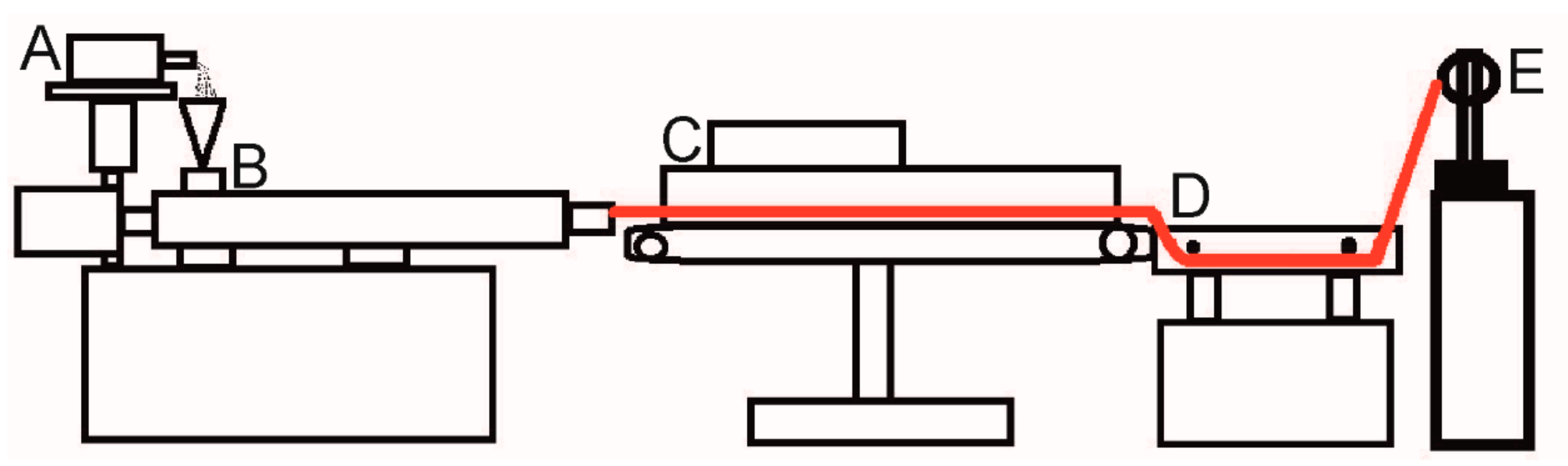
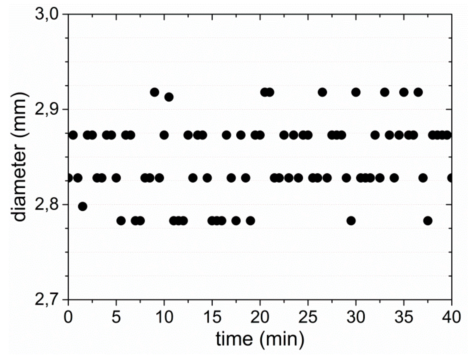
2.2. Extrusion
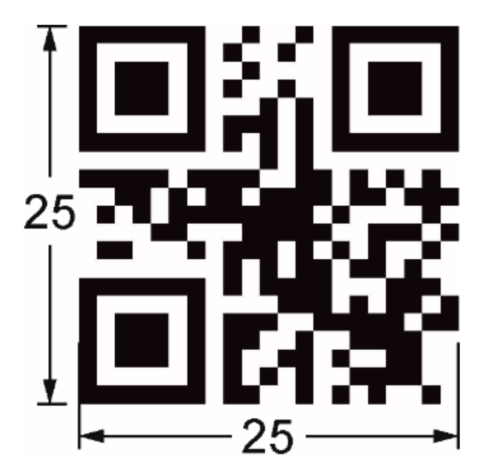
2.3. Virtual Design
2.4. Fused Filament Fabrication (3D Printing)
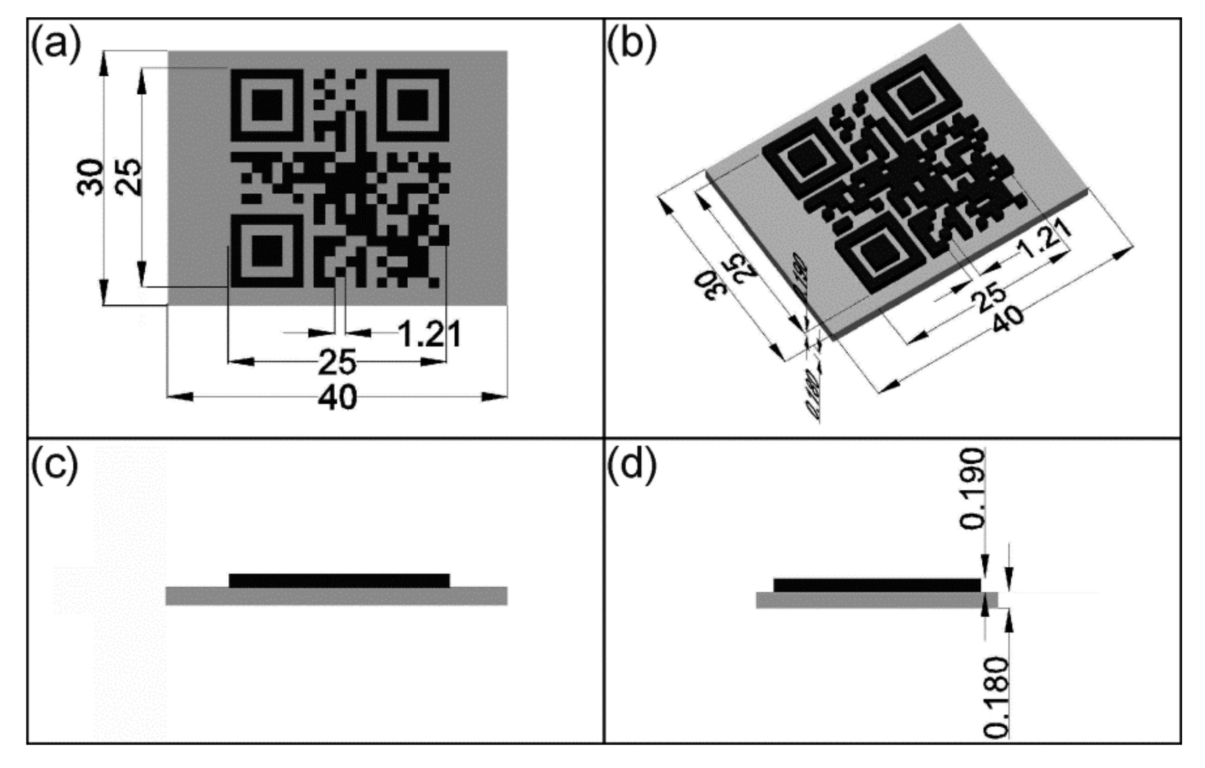
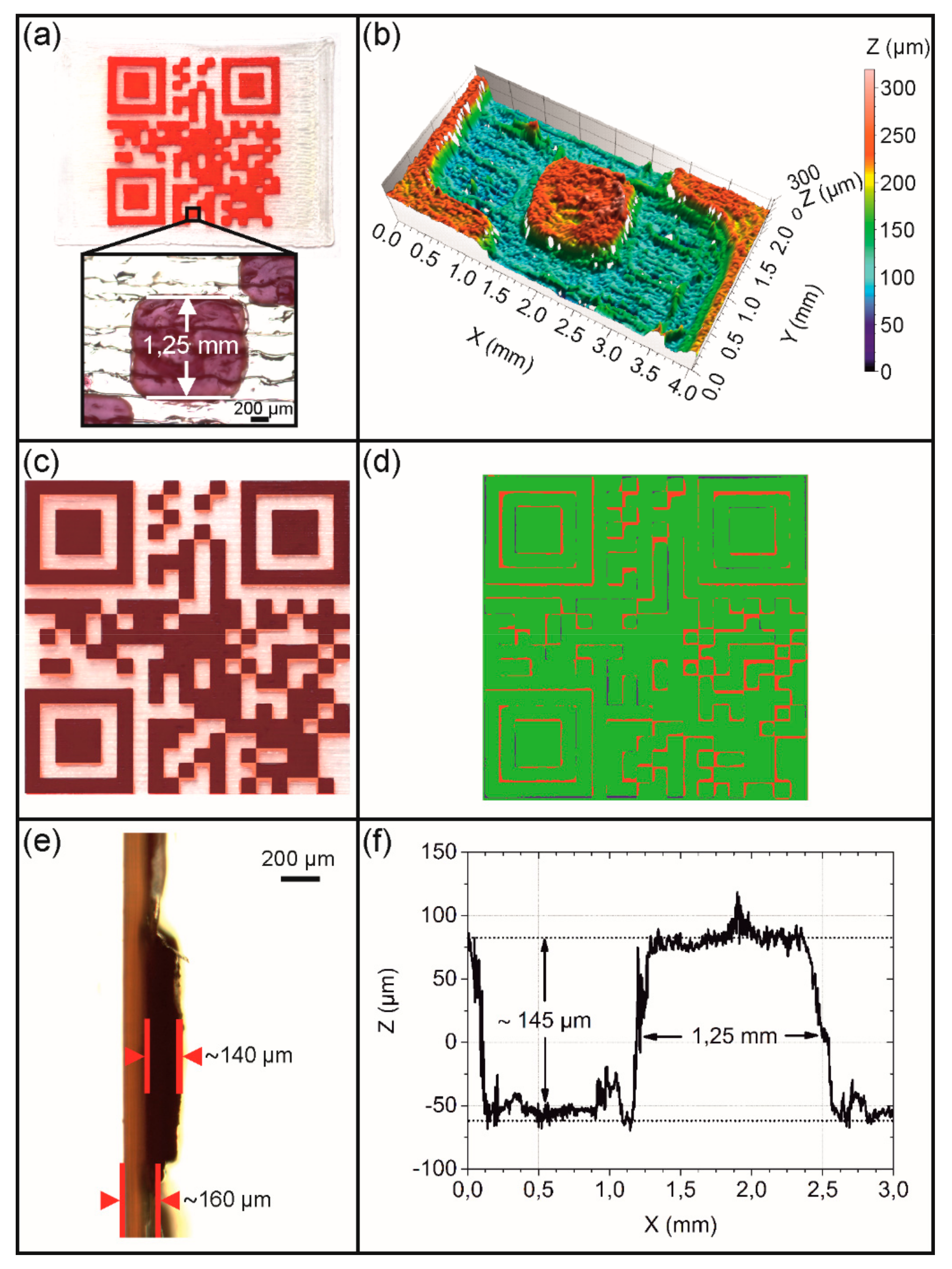
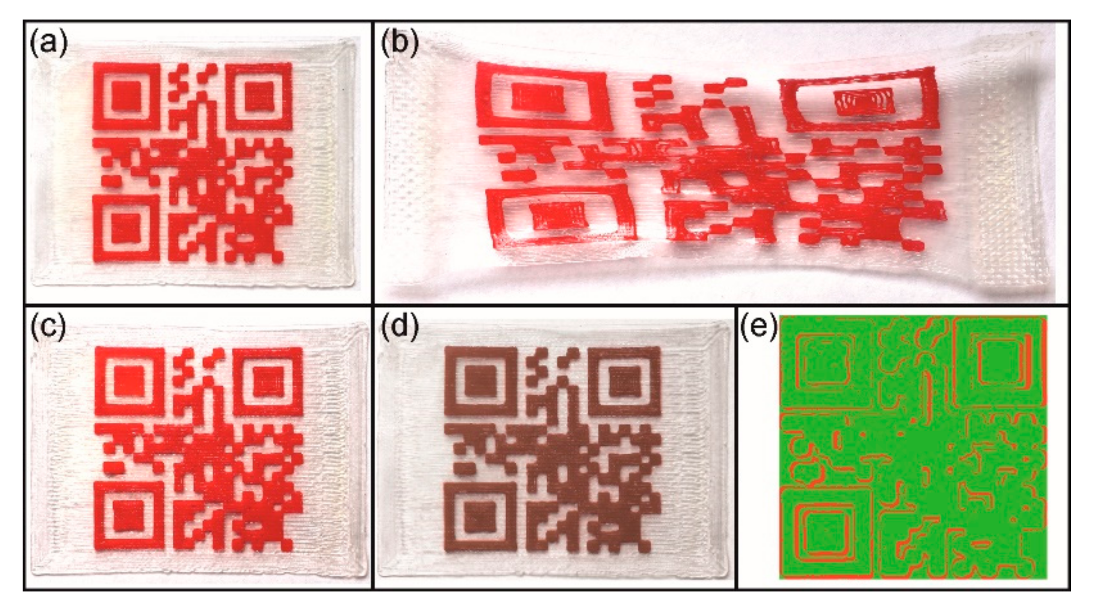
- Type 1: The substrate was printed with non-dyed PEU using a 400 µm nozzle and a target layer thickness of 180 µm. The elevation was built from red PEU with a 100 µm nozzle.
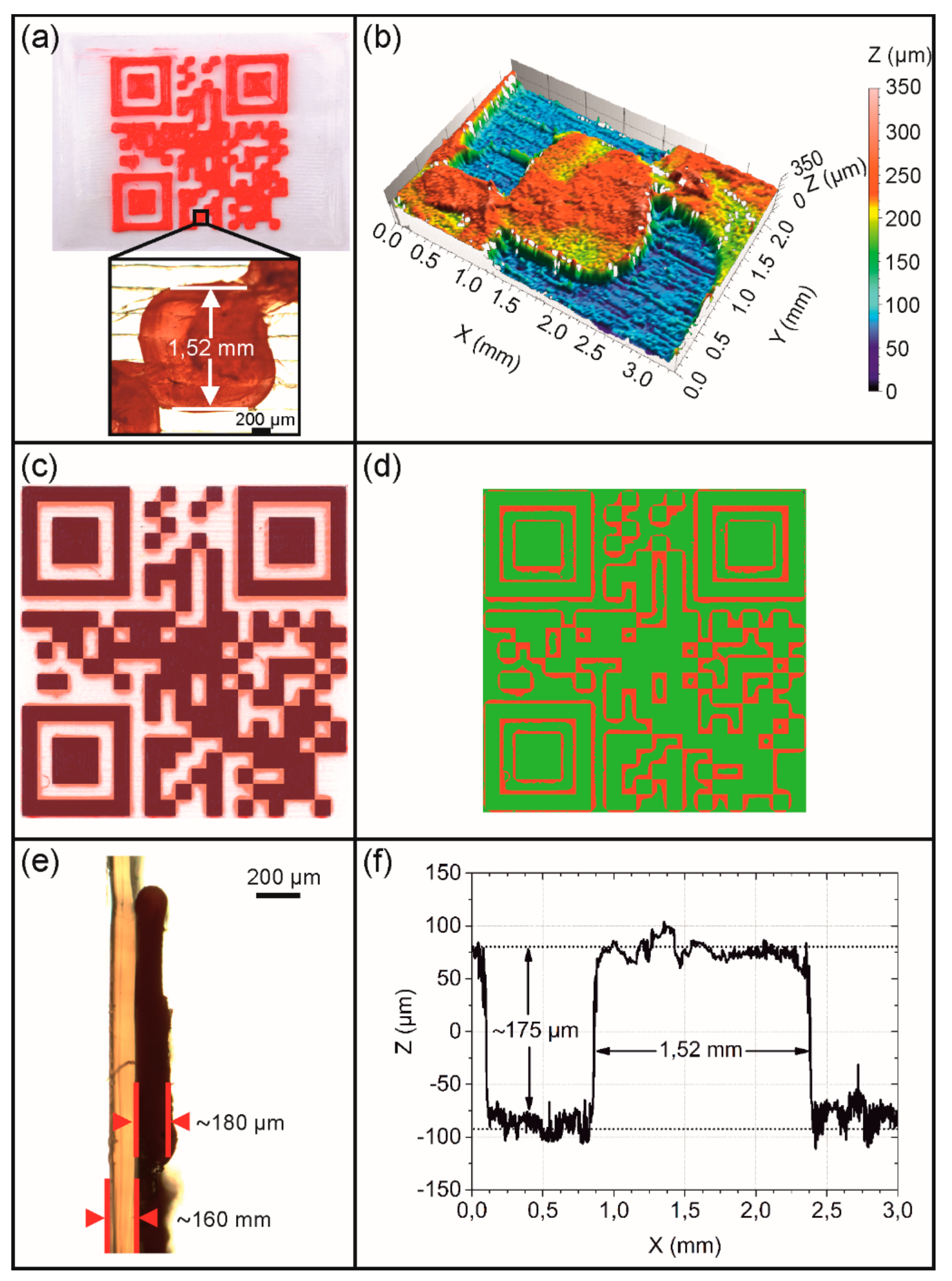
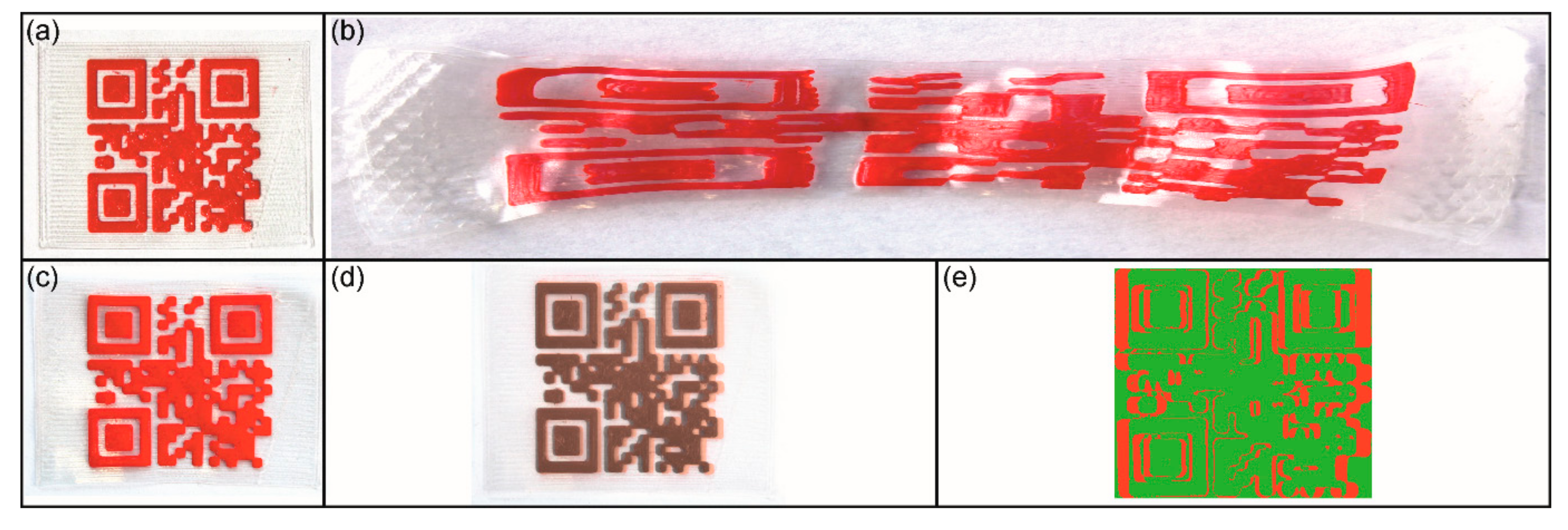
- Type 2: In analogy to the type 1 QR code carrier, the substrate was printed with non-dyed PEU using a 400 µm nozzle. Again, a target layer thickness of 180 µm was selected for the substrate, but the elevation was built with red PEU employing a 400 µm nozzle.
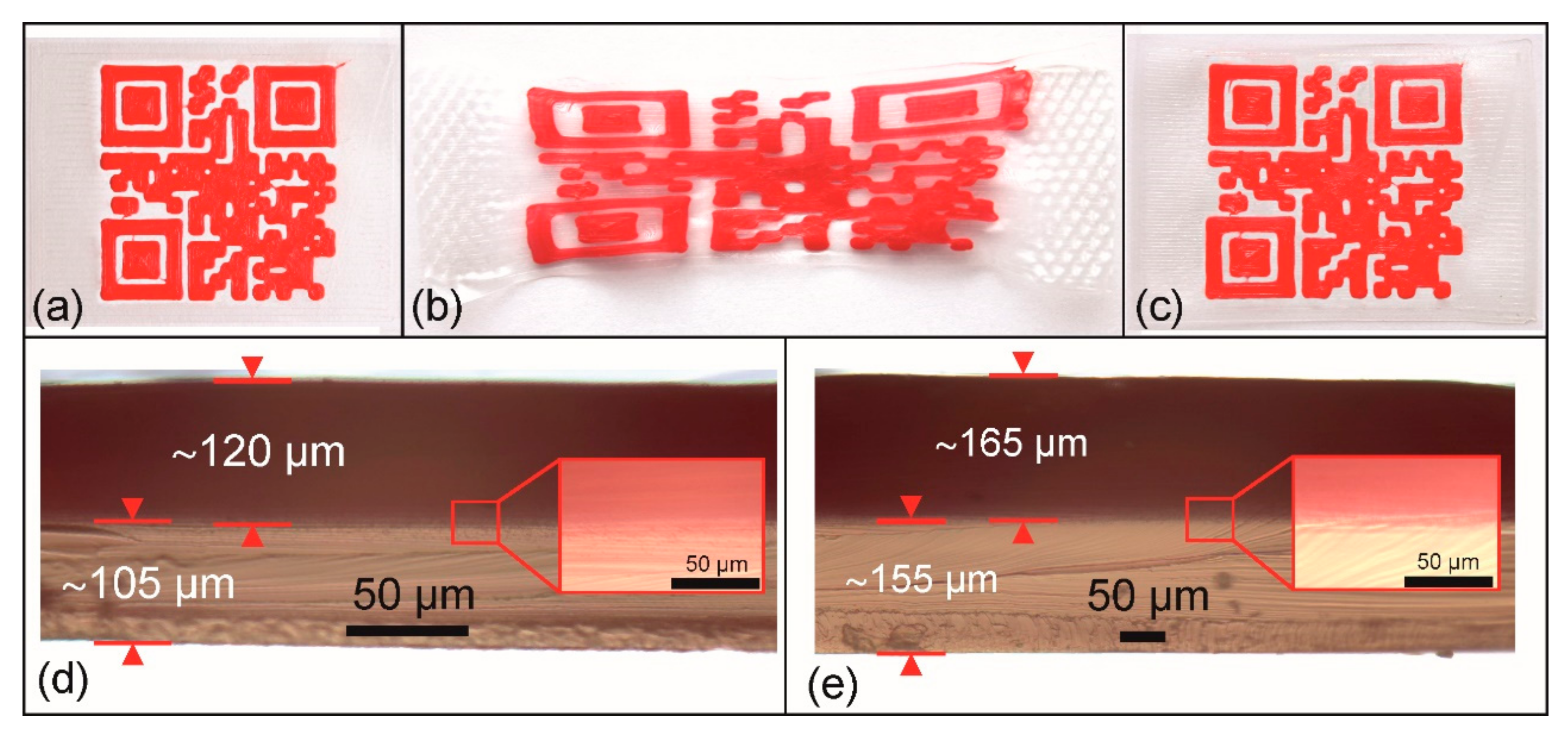
- Type 3: Similar as in the previous cases, the substrate was printed with non-dyed PEU using a 400 µm nozzle, but this time a reduced target layer thickness of 15 µm was selected. The elevation was built with red PEU using a 400 µm nozzle.
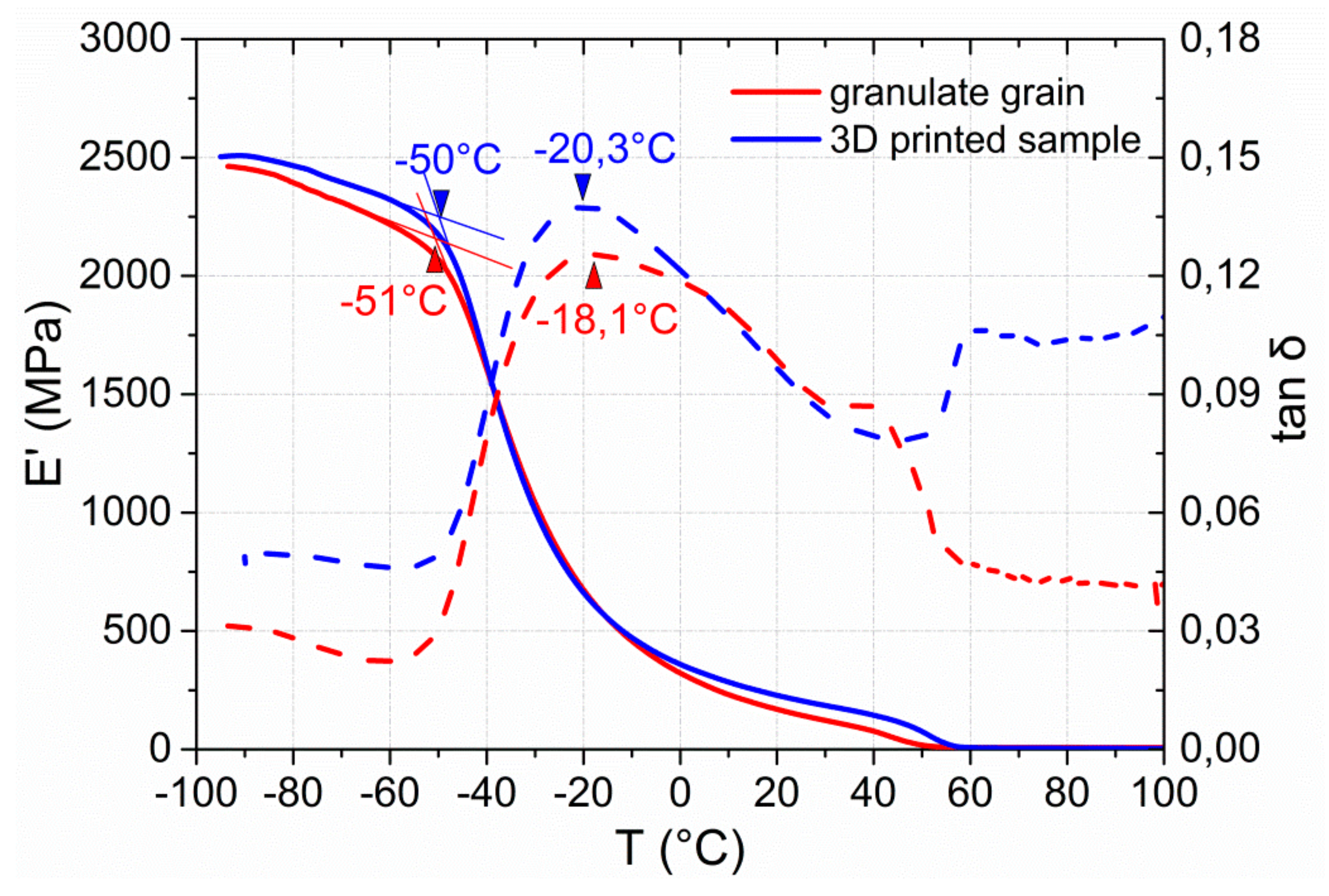
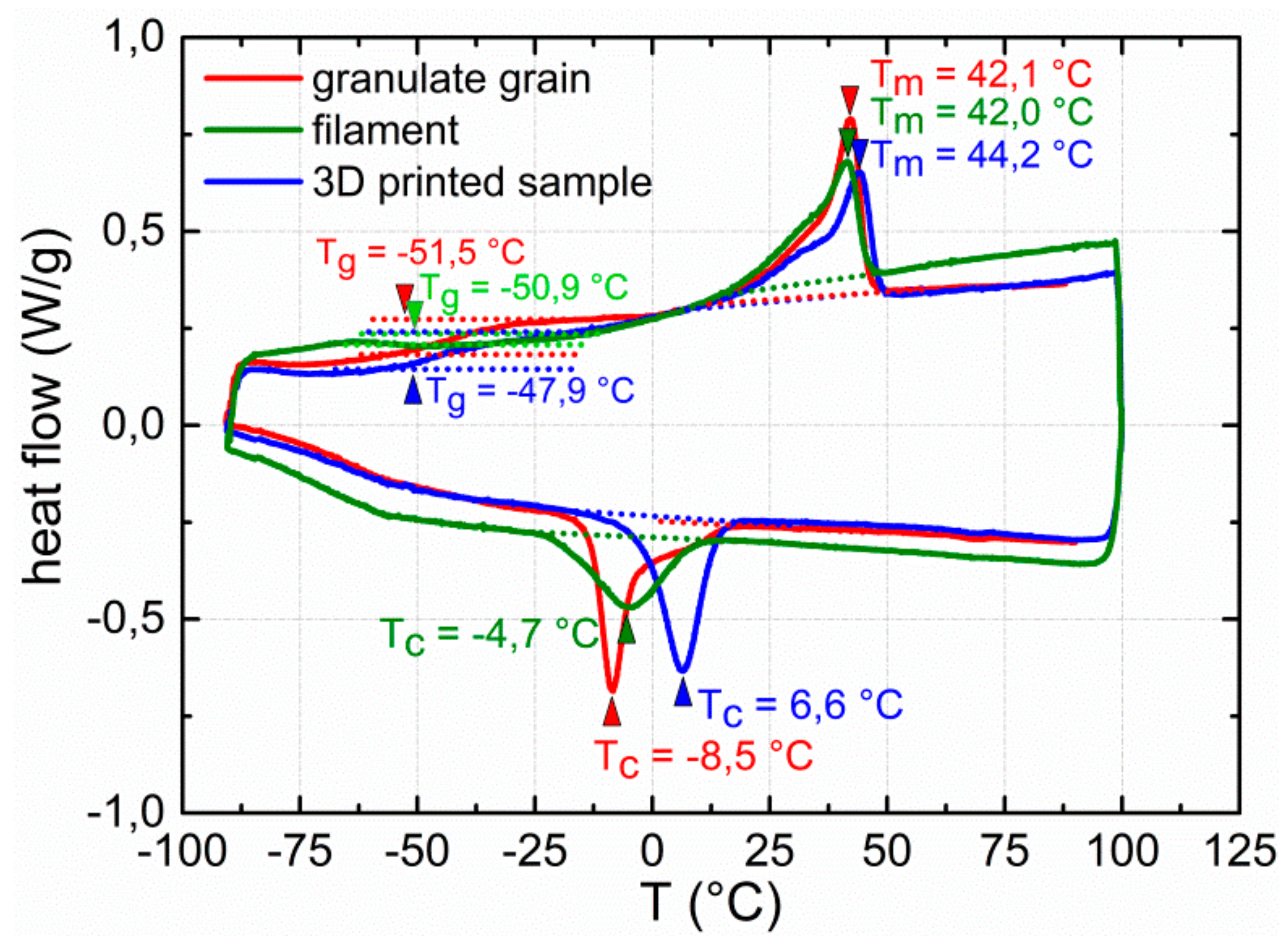
2.5. Characterization of Thermal Properties
2.6. Characterization of Print Quality
2.7. Programming and Characterization of Shape Memory Properties
3. Results and Discussion
4. Conclusions
Author Contributions
Funding
Acknowledgments
Conflicts of Interest
References
- Wendel, B.; Rietzel, D.; Kühnlein, F.; Feulner, R.; Hülder, G.; Schmachtenberg, E. Additive Processing of Polymers. Macromol. Mater. Eng. 2008, 293, 799–809. [Google Scholar] [CrossRef]
- Mohamed, O.A.; Masood, S.H.; Bhowmik, J.L. Optimization of fused deposition modeling process parameters: A review of current research and future prospects. Adv. Manuf. 2015, 3, 42–53. [Google Scholar] [CrossRef]
- Ligon, S.C.; Liska, R.; Stampfl, J.; Gurr, M.; Mülhaupt, R. Polymers for 3D Printing and Customized Additive Manufacturing. Chem. Rev. 2017, 117, 10212–10290. [Google Scholar] [CrossRef] [PubMed]
- Lee, A.Y.; An, J.; Chua, C.K. Two-Way 4D Printing: A Review on the Reversibility of 3D-Printed Shape Memory Materials. Engineering 2017, 3, 663–674. [Google Scholar] [CrossRef]
- Boydston, A.J.; Cao, B.; Nelson, A.; Ono, R.J.; Saha, A.; Schwartz, J.J.; Thrasher, C.J. Additive manufacturing with stimuli-responsive materials. J. Mater. Chem. A 2018, 6, 20621–20645. [Google Scholar] [CrossRef]
- Lendlein, A.; Kelch, S. Shape-Memory Polymers. Angew. Chem. Int. Ed. 2002, 41, 2034–2057. [Google Scholar] [CrossRef]
- Dietsch, B.; Tong, T. A review—features and benefits of shape memory polymers (SMPs). J. Adv. Mater. 2007, 39, 3–12. [Google Scholar]
- Liu, C.; Qin, H.; Mather, P.T. Review of progress in shape-memory polymers. J. Mater. Chem. 2007, 17, 1543–1558. [Google Scholar] [CrossRef]
- Ratna, D.; Karger-Kocsis, J. Recent advances in shape memory polymers and composites: A review. J. Mater. Sci. 2008, 43, 254–269. [Google Scholar] [CrossRef]
- Pretsch, T. Review on the functional determinants and durability of shape memory polymers. Polymers 2010, 2, 120–158. [Google Scholar] [CrossRef]
- Sun, L.; Huang, W.M.; Ding, Z.; Zhao, Y.; Wang, C.C.; Purnawali, H.; Tang, C. Stimulus-responsive shape memory materials: A review. Mater. Des. 2012, 33, 577–640. [Google Scholar] [CrossRef]
- Kim, B.K.; Lee, S.Y.; Xu, M. Polyurethanes having shape memory effects. Polymer 1996, 37, 5781–5793. [Google Scholar] [CrossRef]
- Li, F.; Zhang, X.; Hou, J.; Xu, M.; Luo, X.; Ma, D.; Kim, B.K. Studies on thermally stimulated shape memory effect of segmented polyurethanes. J. Appl. Polym. Sci. 1997, 64, 1511–1516. [Google Scholar] [CrossRef]
- Lee, B.S.; Chun, B.C.; Chung, Y.-C.; Sul, K.I.; Cho, J.W. Structure and thermomechanical properties of polyurethane block copolymers with shape memory effect. Macromolecules 2001, 34, 6431–6437. [Google Scholar] [CrossRef]
- Ji, F.L.; Hu, J.L.; Li, T.C.; Wong, Y.W. Morphology and shape memory effect of segmented polyurethanes. Part І: With crystalline reversible phase. Polymer 2007, 48, 5133–5145. [Google Scholar] [CrossRef]
- Pereira, I.M.; Oréfice, R.L. The morphology and phase mixing studies on poly(ester–urethane) during shape memory cycle. J. Mater. Sci. 2010, 45, 511–522. [Google Scholar] [CrossRef]
- Huang, W.M.; Yang, B.; Zhao, Y.; Ding, Z. Thermo-moisture responsive polyurethane shape-memory polymer and composites: A review. J. Mater. Chem. 2010, 20, 3367–3381. [Google Scholar] [CrossRef]
- Wang, W.; Jin, Y.; Ping, P.; Chen, X.; Jing, X.; Su, Z. Structure evolution in segmented poly(ester urethane) in shape-memory process. Macromolecules 2010, 43, 2942–2947. [Google Scholar] [CrossRef]
- Pretsch, T.; Müller, W.W. Shape memory poly(ester urethane) with improved hydrolytic stability. Polym. Degrad. Stab. 2010, 95, 880–888. [Google Scholar] [CrossRef]
- Müller, W.W.; Pretsch, T. Hydrolytic aging of crystallizable shape memory poly(ester urethane): Effects on the thermo-mechanical properties and visco-elastic modeling. Eur. Polym. J. 2010, 46, 1745–1758. [Google Scholar] [CrossRef]
- Petchsuk, A.; Klinsukhon, W.; Sirikittikul, D.; Prahsarn, C. Parameters affecting transition temperatures of poly(lactic acid-co-polydiols) copolymer-based polyester urethanes and their shape memory behavior. Polym. Adv. Technol. 2012, 23, 1166–1173. [Google Scholar] [CrossRef]
- Bothe, M.; Emmerling, F.; Pretsch, T. Poly(ester urethane) with varying polyester chain length: polymorphism and shape-memory behavior. Macromol. Chem. Phys. 2013, 214, 2683–2693. [Google Scholar] [CrossRef]
- Liu, W.; Zhang, R.; Huang, M.; Dong, X.; Xu, W.; Wang, Y.; Hu, G.-H.; Zhu, J. Synthesis and shape memory property of segmented poly(ester urethane) with poly(butylene 1,4-cyclohexanedicarboxylate) as the soft segment. RSC Adv. 2016, 6, 95527–95534. [Google Scholar] [CrossRef]
- Ren, H.; Mei, Z.; Chen, S.; Zhuo, H.; Chen, S.; Yang, H.; Zuo, J.; Ge, Z. A new strategy for designing multifunctional shape memory polymers with amine-containing polyurethanes. J. Mater. Sci 2016, 51, 9131–9144. [Google Scholar] [CrossRef]
- Mirtschin, N.; Pretsch, T. Programming of one- and two-step stress recovery in a poly(ester urethane). Polymers 2017, 9, 98. [Google Scholar] [CrossRef] [PubMed]
- Hendrikson, W.J.; Rouwkema, J.; Clementi, F.; van Blitterswijk, C.A.; Farè, S.; Moroni, L. Towards 4D printed scaffolds for tissue engineering: Exploiting 3D shape memory polymers to deliver time-controlled stimulus on cultured cells. Biofabrication 2017, 9, 31001. [Google Scholar] [CrossRef]
- Raasch, J.; Ivey, M.; Aldrich, D.; Nobes, D.S.; Ayranci, C. Characterization of polyurethane shape memory polymer processed by material extrusion additive manufacturing. Addit. Manuf. 2015, 8, 132–141. [Google Scholar] [CrossRef]
- Yang, Y.; Chen, Y.; Wei, Y.; Li, Y. 3D printing of shape memory polymer for functional part fabrication. Int. J. Adv. Manuf. Technol. 2016, 84, 2079–2095. [Google Scholar] [CrossRef]
- Villacres, J.; Nobes, D.; Ayranci, C. Additive manufacturing of shape memory polymers: Effects of print orientation and infill percentage on mechanical properties. Rapid Prototyp. J. 2018, 24, 744–751. [Google Scholar] [CrossRef]
- Monzón, M.D.; Paz, R.; Pei, E.; Ortega, F.; Suárez, L.A.; Ortega, Z.; Alemán, M.E.; Plucinski, T.; Clow, N. 4D printing: Processability and measurement of recovery force in shape memory polymers. Int. J. Adv. Manuf. Technol. 2017, 89, 1827–1836. [Google Scholar] [CrossRef]
- Jung, Y.C.; Cho, J.W. Application of shape memory polyurethane in orthodontic. J. Mater. Sci. Mater. Med. 2010, 21, 2881–2886. [Google Scholar] [CrossRef] [PubMed]
- Nardo, L.D.; Bertoldi, S.; Tanzi, M.C.; Haugen, H.J.; Farè, S. Shape memory polymer cellular solid design for medical applications. Smart Mater. Struct. 2011, 20, 035004. [Google Scholar] [CrossRef]
- Hu, J.; Meng, H.; Li, G.; Ibekwe, S.I. A review of stimuli-responsive polymers for smart textile applications. Smart Mater. Struct. 2012, 21, 053001. [Google Scholar] [CrossRef]
- Ahmad, M.; Luo, J.; Miraftab, M. Feasibility study of polyurethane shape-memory polymer actuators for pressure bandage application. Sci. Technol. Adv. Mater. 2012, 13, 015006. [Google Scholar] [CrossRef] [PubMed]
- Liu, Y.; Du, H.; Liu, L.; Leng, J. Shape memory polymers and their composites in aerospace applications: A review. Smart Mater. Struct. 2014, 23, 023001. [Google Scholar] [CrossRef]
- Pilate, F.; Toncheva, A.; Dubois, P.; Raquez, J.-M. Shape-memory polymers for multiple applications in the materials world. Eur. Polym. J. 2016, 80, 268–294. [Google Scholar] [CrossRef]
- Zhao, Q.; Qi, H.J.; Xie, T. Recent progress in shape memory polymer: New behavior, enabling materials, and mechanistic understanding. J. Prog. Polym. Sci. 2015, 49–50, 79–120. [Google Scholar] [CrossRef]
- Wang, K.; Strandman, S.; Zhu, X.X. A mini review: Shape memory polymers for biomedical applications. Front. Chem. Sci. Eng. 2017, 11, 143–153. [Google Scholar] [CrossRef]
- Patil, D.; Song, G. A review of shape memory material’s applications in the offshore oil and gas industry. Smart Mater. Struct. 2017, 26, 093002. [Google Scholar] [CrossRef]
- Hosseini, S.M.; Rihani, R.; Batchelor, B.; Stiller, A.M.; Pancrazio, J.J.; Voit, W.E.; Ecker, M. Softening Shape Memory Polymer Substrates for Bioelectronic Devices with Improved Hydrolytic Stability. Front. Mater. 2018, 5, 66. [Google Scholar] [CrossRef]
- Pretsch, T.; Ecker, M.; Schildhauer, M.; Maskos, M. Switchable information carriers based on shape memory polymer. J. Mater. Chem. 2012, 22, 7757. [Google Scholar] [CrossRef]
- Ecker, M.; Pretsch, T. Durability of switchable QR code carriers under hydrolytic and photolytic conditions. Smart Mater. Struct. 2013, 22, 094005. [Google Scholar] [CrossRef]
- Li, W.; Liu, Y.; Leng, J. Programmable and shape-memorizing information carriers. ACS Appl. Mater. Interfaces 2017, 9, 44792–44798. [Google Scholar] [CrossRef] [PubMed]
- Fritzsche, N.; Pretsch, T. Programming of temperature-memory onsets in a semicrystalline polyurethane elastomer. Macromolecules 2014, 47, 5952–5959. [Google Scholar] [CrossRef]
- Ecker, M.; Pretsch, T. Multifunctional poly(ester urethane) laminates with encoded information. RSC Adv. 2014, 4, 286–292. [Google Scholar] [CrossRef]
- Ecker, M.; Pretsch, T. Novel design approaches for multifunctional information carriers. RSC Adv. 2014, 4, 46680–46688. [Google Scholar] [CrossRef]
- Mirtschin, N.; Pretsch, T. Designing temperature-memory effects in semicrystalline polyurethane. RSC Adv. 2015, 5, 46307–46315. [Google Scholar] [CrossRef]
- QR Code Generator—Create QR Codes for Free (Logo, T-Shirt, vCard, EPS). Available online: http://goqr.me/ (accessed on 19 March 2019).
- ISO/IEC 18004:2006. Available online: https://www.iso.org/standard/43655.html (accessed on 19 March 2019).
- AutoCAD For Mac & Windows | CAD Software | Autodesk. Available online: https://www.autodesk.eu/products/autocad/overview (accessed on 19 March 2019).
- Ultimaker Cura: Advanced 3D Printing Software, Made Accessible | Ultimaker. Available online: https://ultimaker.com/en/products/ultimaker-cura-software (accessed on 19 March 2019).
- Ultimaker 3 Specifications | Ultimaker. Available online: https://ultimaker.com/en/products/ultimaker-3/specifications (accessed on 19 March 2019).
- Scanning Probe Microscopy. Available online: https://www.digitalsurf.com/software-solutions/scanning-probe-microscopy/ (accessed on 19 March 2019).
- Free Microscope Software ZEN Lite from ZEISS Microscopy. Available online: https://www.zeiss.com/microscopy/int/products/microscope-software/zen-lite.html (accessed on 19 March 2019).
- ImageJ. Available online: https://imagej.nih.gov/ij/ (accessed on 29 March 2019).
- ParaView. Available online: https://www.paraview.org/ (accessed on 29 March 2019).
- SamMobile. Optical Reader 4.4.07. Available online: https://www.sammobile.com/apk/optical-reader/optical-reader-4-4-07/ (accessed on 19 March 2019).
- Fuenmayor, E.; Forde, M.; Healy, A.V.; Devine, D.M.; Lyons, J.G.; McConville, C.; Major, I. Material Considerations for Fused-Filament Fabrication of Solid Dosage Forms. Pharmaceutics 2018, 10, 44. [Google Scholar] [CrossRef]
- Chen, S.; Hu, J.; Liu, Y.; Liem, H.; Zhu, Y.; Meng, Q. Effect of molecular weight on shape memory behavior in polyurethane films. Polym. Int. 2007, 56, 1128–1134. [Google Scholar] [CrossRef]
- Chen, S.; Hu, J.; Liu, Y.; Liem, H.; Zhu, Y.; Liu, Y. Effect of SSL and HSC on morphology and properties of PHA based SMPU synthesized by bulk polymerization method. J. Polym. Sci. B Polym. Phys. 2007, 45, 444–454. [Google Scholar] [CrossRef]
- Petrović, Z.S.; Milić, J.; Zhang, F.; Ilavsky, J. Fast-Responding Bio-Based Shape Memory Thermoplastic Polyurethanes. Polymer 2017, 121, 26–37. [Google Scholar] [CrossRef] [PubMed]
- Takahashi, T.; Hayashi, N.; Hayashi, S. Structure and properties of shape-memory polyurethane block copolymers. J. Appl. Polym. Sci. 1996, 60, 1061–1069. [Google Scholar] [CrossRef]
- Ecker, M.; Pretsch, T. Freely configurable Functionalization Tool for switchable Information Carriers. In Materials Challenges and Testing for Manufacturing, Mobility, Biomedical Applications and Climate; Udomkichdecha, W., Böllinghaus, T., Manonukul, A., Lexow, J., Eds.; Springer: New York, NY, USA, 2014; pp. 25–35. ISBN 978-3-319-11339-5. [Google Scholar]
- Quinlan, H.E.; Hasan, T.; Jaddou, J.; Hart, A.J. Industrial and Consumer Uses of Additive Manufacturing: A Discussion of Capabilities, Trajectories, and Challenges. J. Ind. Ecol. 2017, 21, S15–S20. [Google Scholar] [CrossRef]
- Garces, I.T.; Aslanzadeh, S.; Boluk, Y.; Ayranci, C. Effect of Moisture on Shape Memory Polyurethane Polymers for Extrusion-Based Additive Manufacturing. Materials 2019, 12, 244. [Google Scholar] [CrossRef] [PubMed]
- Kashyap, D.; Kishore Kumar, P.; Kanagaraj, S. 4D printed porous radiopaque shape memory polyurethane for endovascular embolization. Addit. Manuf. 2018, 24, 687–695. [Google Scholar] [CrossRef]
- Berwind, M.F.; Kamas, A.; Eberl, C. A Hierarchical Programmable Mechanical Metamaterial Unit Cell Showing Metastable Shape Memory. Adv. Eng. Mater. 2018, 20, 1800771. [Google Scholar] [CrossRef]


| Specifications | Substrate (Non-Dyed PEU) | Elevation (Red PEU) | ||
|---|---|---|---|---|
| Type of QR code carrier | 1, 2 | 3 | 1 | 2, 3 |
| Diameter of the nozzle (µm) | 400 | 400 | 100 | 400 |
| Temperature of the nozzle (°C) | 225 | 225 | 190 | 190 |
| Speed of print head (mm·s−1) | 50 | 50 | 4 | 7 |
| Build rate (ml·h−1) | 34.2 | 34.2 | 5.4 | 22.8 |
| Build platform temperature (°C) | 23 | 23 | 23 | 23 |
| Number of layers | 1 | 1 | 3 | 1 |
| Layer height (µm) | 180 | 15 | 63 | 190 |
© 2019 by the authors. Licensee MDPI, Basel, Switzerland. This article is an open access article distributed under the terms and conditions of the Creative Commons Attribution (CC BY) license (http://creativecommons.org/licenses/by/4.0/).
Share and Cite
Chalissery, D.; Pretsch, T.; Staub, S.; Andrä, H. Additive Manufacturing of Information Carriers Based on Shape Memory Polyester Urethane. Polymers 2019, 11, 1005. https://doi.org/10.3390/polym11061005
Chalissery D, Pretsch T, Staub S, Andrä H. Additive Manufacturing of Information Carriers Based on Shape Memory Polyester Urethane. Polymers. 2019; 11(6):1005. https://doi.org/10.3390/polym11061005
Chicago/Turabian StyleChalissery, Dilip, Thorsten Pretsch, Sarah Staub, and Heiko Andrä. 2019. "Additive Manufacturing of Information Carriers Based on Shape Memory Polyester Urethane" Polymers 11, no. 6: 1005. https://doi.org/10.3390/polym11061005
APA StyleChalissery, D., Pretsch, T., Staub, S., & Andrä, H. (2019). Additive Manufacturing of Information Carriers Based on Shape Memory Polyester Urethane. Polymers, 11(6), 1005. https://doi.org/10.3390/polym11061005