Stabilization of Electrospun Nanofiber Mats Used for Filters by 3D Printing


1
Faculty of Mechatronics and Mechanical Engineering, Kielce University of Technology, 25-314 Kielce, Poland
2
Faculty of Engineering and Mathematics, Bielefeld University of Applied Sciences, 33619 Bielefeld, Germany
3
Ecole Nationale d’Ingénieurs de Sfax, Sfax 3038, Tunisia
*
Author to whom correspondence should be addressed.
Polymers 2019, 11(10), 1618; https://doi.org/10.3390/polym11101618
Submission received: 12 September 2019
/
Revised: 3 October 2019
/
Accepted: 4 October 2019
/
Published: 6 October 2019
(This article belongs to the Special Issue 3D and 4D Printing of (Bio)Materials)
Abstract
:Electrospinning is a well-known technology used to create nanofiber mats from diverse polymers and other materials. Due to their large surface-to-volume ratio, such nanofiber mats are often applied as air or water filters. Especially the latter, however, have to be mechanically highly stable, which is challenging for common nanofiber mats. One of the approaches to overcome this problem is gluing them on top of more rigid objects, integrating them in composites, or reinforcing them using other technologies to avoid damage due to the water pressure. Here, we suggest another solution. While direct 3D printing with the fused deposition modeling (FDM) technique on macroscopic textile fabrics has been under examination by several research groups for years, here we report on direct FDM printing on nanofiber mats for the first time. We show that by choosing the proper height of the printing nozzle above the nanofiber mat, printing is possible for raw polyacrylonitrile (PAN) nanofiber mats, as well as for stabilized and even more brittle carbonized material. Under these conditions, the adhesion between both parts of the composite is high enough to prevent the nanofiber mat from being peeled off the 3D printed polymer. Abrasion tests emphasize the significantly increased mechanical properties, while contact angle examinations reveal a hydrophilicity between the original values of the electrospun and the 3D printed materials.

1. Introduction
Electrospinning can be used to create continuous nanofibers or nanofiber mats, typically with diameters in the range of tens to hundreds of nanometers [1,2,3]. In needle-based technology, a polymer solution or melt is pressed out of a syringe through a fine needle and stretched in a strong electric field, building a so-called Taylor cone while being drawn to a substrate [4]. Needleless technologies often apply rotating cylinders or wires, which are constantly coated with polymer melt or solution [5].
Due to their large surface space, such nanofiber mats are often used in applications that necessitate a large contact area of the material with the environment, such as catalyzers [6], medical wound dressing [7,8,9], biotechnological applications [10,11,12], or novel filter materials [13,14,15,16,17,18].
These fine nanofiber mats with typical areal weights of a few grams per square meter or even less, however, are mechanically not very stable [19], making an additional stabilization necessary in many cases. This is of special relevance in the case of electrospun water or oil filters [20]. Diverse approaches have been reported in the literature to solve this problem, such as heat pressing [14,21], ultrasonic welding of several nanofiber mats [22], coating the nanofiber mats [23], laminating the nanofiber mats [24], crosslinking of neighboring fibers [25], or embedding the nanofiber mats into textile composites [26].
Additive manufacturing technologies have many applications, both in the aerospace, automotive, and prototyping industries. At present, however, many research works focus on the study of mechanical properties and the dimensional accuracy of manufactured models [27,28,29]. Here, we report on a novel approach to combine both of the aforementioned technologies, using 3D printing on nanofiber mats to increase their mechanical stability.
Generally, 3D printing by fused deposition modeling (FDM) on macroscopic textile fabrics is under investigation in many research groups, aiming at increasing the adhesion between both parts of the composite by mechanical, thermal, or chemical methods [30,31,32,33,34,35,36,37,38]. Direct 3D printing on electrospun nanofiber mats prepared with different equipment, however, has, to the best of our knowledge, not yet been reported in the scientific literature. Reports of combinations of both technologies by electrospinning on 3D printed objects [39,40,41], on objects for which 3D printed negative forms were created [42], or by creating 3D printing inks from electrospun nanofibers [43], have been recently published. Only one report on a special self-built machine, created to produce alternatingly 3D-printed and electrospun layers by a needle-based method, can be found in the scientific literature [44]. Our results reported here go without such specialized equipment, but evaluate 3D printing by a common FDM printer on needleless electrospun nanofiber mats.
2. Materials and Methods
For electrospinning, the needleless electrospinning machine “Nanospider Lab” (Elmarco Ltd., Liberec, Czech Republic) was used by applying the following spinning parameters: high voltage 50–80 kV, nozzle diameter 0.8–0.9 mm, carriage speed 100 mm/s, bottom electrode/substrate distance 240 mm, ground electrode/substrate distance 50 mm, temperature in the chamber 22–23 °C, and relative humidity in the chamber 32–33%. As substrates, either a polypropylene nonwoven or an aluminum foil was used. On the latter, PAN nanofibers mats adhere strongly [45], allowing one to use the aluminum foil as a relatively rigid substrate during 3D printing. Spinning was carried out for 10 min (on aluminum), 20 min (in case of 70 kV), or 30 min (in case of 50 kV) to create sufficiently thick nanofiber mats.
The spinning solution was prepared from 16% polyacrylonitrile (PAN) dissolved in dimethyl sulphoxide (DMSO, min. 99.9%, purchased from S3 Chemicals, Bad Oeynhausen, Germany). PAN was used for this proof-of-concept, since it can be electrospun from the low-toxic DMSO [46] and has been investigated in detail during stabilization and carbonization before [47].
Some nanofiber mats were stabilized in a muffle furnace B150 (Nabertherm, Lilienthal, Germany), at a typical stabilization temperature of 280 °C approached with a heating rate of 1 K/min, followed by isothermal treatment at this temperature for 1 h. Carbonization was performed in a furnace (Carbolite Gero, Neuhausen, Germany) at a temperature of 500 °C, reached with a heating rate of 10 K/min in a nitrogen flow of 150 mL/min (STP) and isothermal treatment at this temperature for 1 h.
On these nanofiber mats, 3D printing was performed using the FDM printer Orcabot XXL (Prodim, The Netherlands) with a nozzle diameter of 0.4 mm, using a layer thickness of 0.2 mm, a nozzle temperature of 190 °C to 210 °C, and different printing bed temperatures between room temperature and 80 °C. The polymer material was poly(lactic acid) (PLA) (purchased from Filamentworld, Neu-Ulm, Germany). A sketch of this process is presented in Figure 1.
For the optical and chemical evaluation of the composites, we used a digital microscope VHX-600D (Keyence, Neu-Isenburg, Germany), a confocal laser scanning microscope (CLSM) VK-8710 (Keyence), and an Excalibur 3100 (Varian, Inc., USA) FTIR spectrometer.
Contact angles were investigated by placing drops of distilled water with a volume of 15 µL onto the samples under examination, taking microscopic images with the aforementioned digital microscope and fitting the angles between the drop contour and the baseline between object and drop.
The abrasion resistance of the nanofiber mats on the 3D printed polymer surface was investigated by a Martindale abrasion tester, working according to ISO 12947, and evaluating the damage on the surface by eye, as defined in the standard, as well as with the aforementioned digital microscope.
3. Results and Discussion
Generally, 3D printing on nanofiber mats was found to require that the distance between printing nozzle and nanofiber mat was controlled exactly. On the one hand, the nanofiber mat breaks at once if the distance is too small or the nozzle even touches the mat, which is opposite to 3D printing on woven, warp knitted, or weft knitted fabrics, where it can be advantageous in terms of adhesion for pressing the filament into the textile by printing “below” the textile surface [31]. On the other hand, if the distance is too large, the contact between both materials is lost, resulting in a very uneven surface (Figure 2a). It must be mentioned that gluing the nanofiber mat onto the printing bed over its entire area results in severe problems to detach the composite from the printing bed afterwards (Figure 2b) and thus cannot be recommended.
In a first test series, nanofiber mats were glued along their borders onto the printing bed, and the printing bed temperature was modified from room temperature to 40 °C, 60 °C, and 80 °C. While a temperature of 60 °C or higher strongly supports the adhesion of a 3D printed PLA layer on the printing bed, here we found that printing at room temperature or at 40 °C showed similar results to using a printing bed temperature of 60 °C, while a temperature of 80 °C resulted in severe problems, prohibiting us from finding a suitable nozzle-nanofiber mat distance in which none of the aforementioned problems occurred. Since heating the printing bed did not show any advantage, the results depicted here were gained with the printing bed at room temperature.
Similarly, different nozzle temperatures between 190 °C and 210 °C were tested, which are well-suited to print PLA. Former experiments revealed that higher temperatures allowed for 3D printing on textile fabrics in a larger distance to reach the same adhesion [48]. Here, however, the possible distance range that was sufficient to create reliable adhesion without breaking the nanofiber mat could not be extended in this way.
Detailed observation of the printing process if the nozzle is slightly too high suggests that the problem of missing adhesion for too large distances between nanofiber mat and printing nozzle may be based on electrostatic repulsion between the 3D printing polymer and the nanofiber mat. In a previous experiment, the electrostatic charging could be significantly reduced by soaking the nanofiber mat into water with a surfactant that was typically negatively charged [49]. Thus, 3D printing was also tested on a nanofiber mat that was soaked in soap water and dried in the air.
In this experiment, however, we found that controlling the distance between nozzle and nanofiber mat was not easier, and the danger of reduced contact between 3D printed polymer and nanofiber mat could not be reduced in this way. Figure 3 depicts an example of a slightly too high nozzle, resulting in a rough surface or even open areas in the 3D printed surface for the longest lines near the diagonal of the sample.
On the other hand, soaking and drying the sample in pure water or soap water before printing on it supports relaxation [49]. In this way, fixing it in a slightly stretched position was simpler than in case of not watered samples, in order to ensure that no elongation of the specimen was possible due to thermal and mechanical impact during printing. Apparently, in spite of the unreached original goal, this pre-treatment is clearly advantageous and should thus always be performed before 3D printing on nanofiber mats.
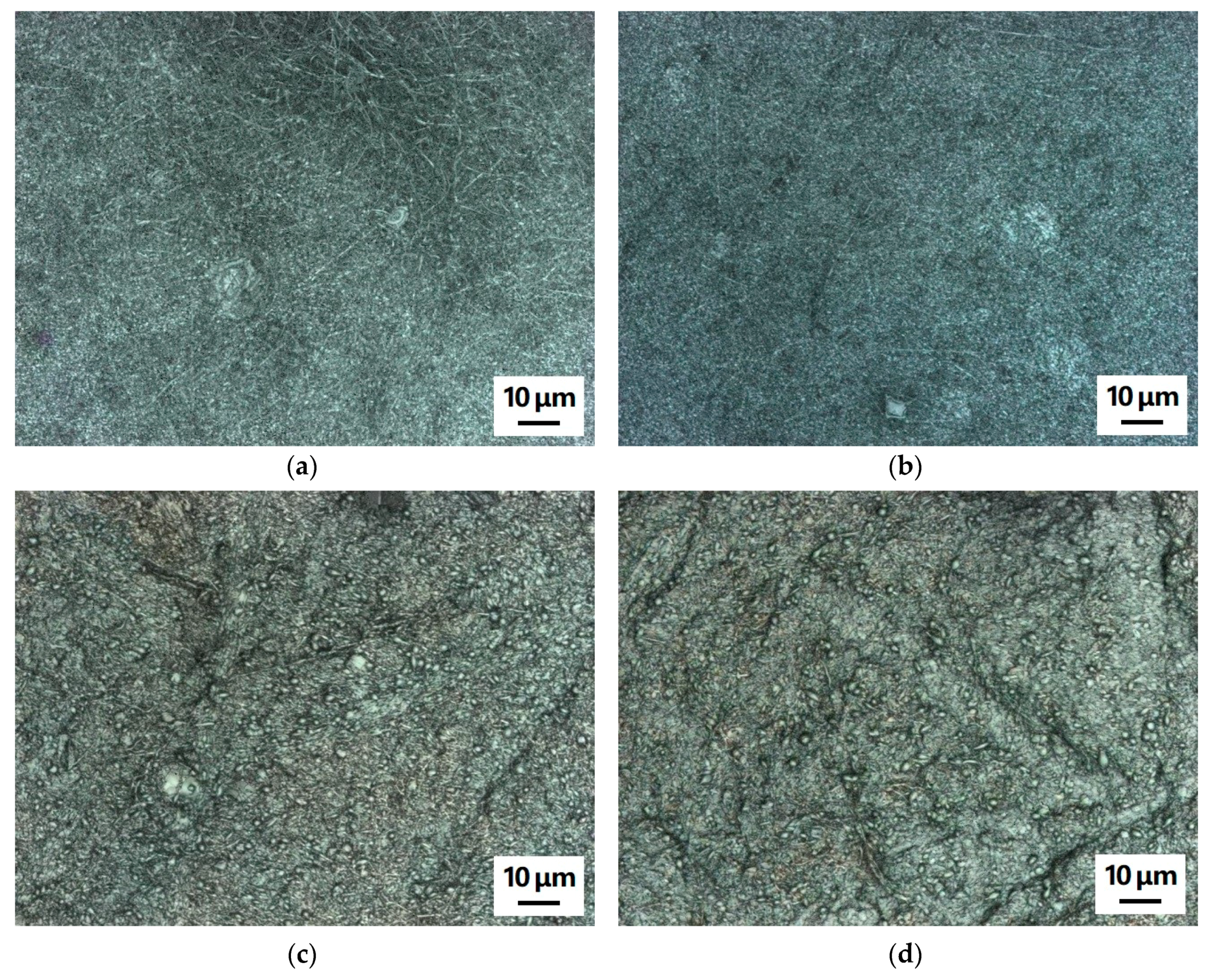
Next, the question arises whether 3D printing with a nozzle temperature of approx. 200 °C may influence the morphology of the nanofiber mat. This is important for the possible application of the nanofiber composites as filter materials. Figure 4 depicts examples of CLSM images, taken on pure nanofiber mats and on nanofiber mats after 3D printing on their backsides to enable comparison. Neither the pure PAN nanofiber mats (Figure 4a,b) or the carbonized ones (Figure 4c,d) show any difference in the morphology. In addition, no color change is visible for the pure PAN nanofiber mat, which might occur for temperature treatment at 180 °C or higher due to the stabilization of the nanofibers [50]. Here, however, either the duration of the temperature treatment is not long enough or the polymer melt touching the nanofiber mat has a temperature below 180 °C so that no stabilization process can start.
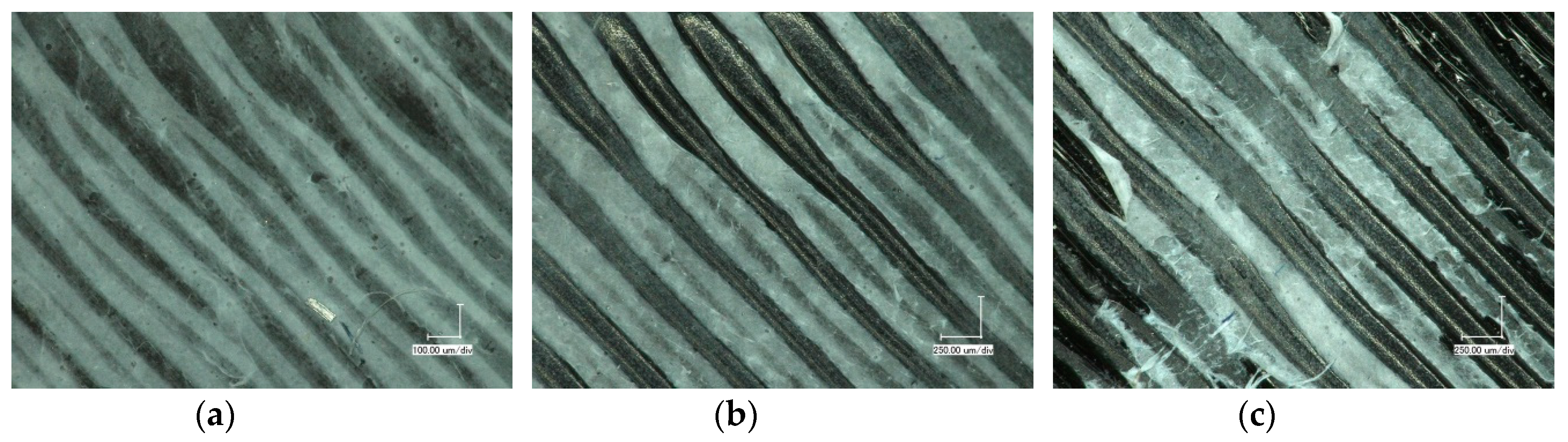
After 3D printing on the nanofiber mats, the composites were detached from the printing bed, and, starting at the edges, the nanofiber mats were carefully peeled from the 3D printed polymer to investigate whether the adhesion between 3D printing polymer and nanofiber mat was stronger or smaller than the adhesion of the layers inside the nanofiber mat. Figure 5 depicts exemplary images of the residues of the nanofiber mats, showing areas with thicker or thinner nanofiber layers left after peeling them off. In the case of the pure PAN nanofiber mats (Figure 5a,b), it is clearly visible that the nanofiber mats were separated inside the fabrics, while even in the areas with the thinnest nanofiber coatings, no positions were found where the nanofiber mats were fully separated from the 3D printing polymer.
This shows clearly that the adhesion between 3D printing polymer and nanofiber mat is uncritical. For better bonding of the fibers inside the mat, either stabilization at higher heating rates than used here [45,50] or crosslinking of the fiber connection points by exposing the nanofiber mat to a solvent vapor [25] can be applied.
The impact of stabilization—even for the small heating rate used here, which does not significantly modify the nanofiber morphology and does not lead to visible conglutinations at the crossing points of neighboring nanofibers—is visible in Figure 5c,d. Thick layers of the stabilized and the carbonized nanofiber mats remain after trying to peel them off, which are, on the other hand, prone to showing micro-cracks, as visible in Figure 5. This suggests either using a chemical method to bond the nanofibers inside the mats better [25] or to fix the whole nanofiber mats on the 3D printed polymer by printing an open grid on the nanofiber mats after the first printing step. Due to the strong relaxation of nanofiber mats during evaporation of residual solvent [49], the opposite procedure of electrospinning on 3D printed layers does not seem to be suitable, but can be expected to result in breaking of the nanofiber mats, which may also happen during electrospinning on the commonly used polypropylene nonwoven.
Next, Figure 6b shows FTIR measurements of PAN nanofiber mats on 3D printed PLA. Figure 6a gives an overview of typical peaks of PLA [51,52,53,54] (grey lines) and PAN [55] (red lines), respectively.
In Figure 6b, the curve measured for the raw PAN nanofiber mat clearly shows peaks of both PLA (grey lines) and PAN (red lines), indicating the composite character of the surface under examination. For the stabilized samples, new peaks can be expected at 1582 cm−1, 1660 cm−1, and approx. 800 cm−1 [55,56,57]. Here, these peaks are clearly visible (blue arrows), while no PLA peaks can be recognized due to the thick nanofiber mat on top of the PLA layer. Finally, for the carbonized layer, the characteristic peaks of the stabilized material are usually nearly completely vanished due to the high absorbance of carbon, leaving only very few functional groups [58]. Again, the peaks resulting from PLA are nearly vanished due to the almost complete carbon nanofiber mat on top of the PLA material.
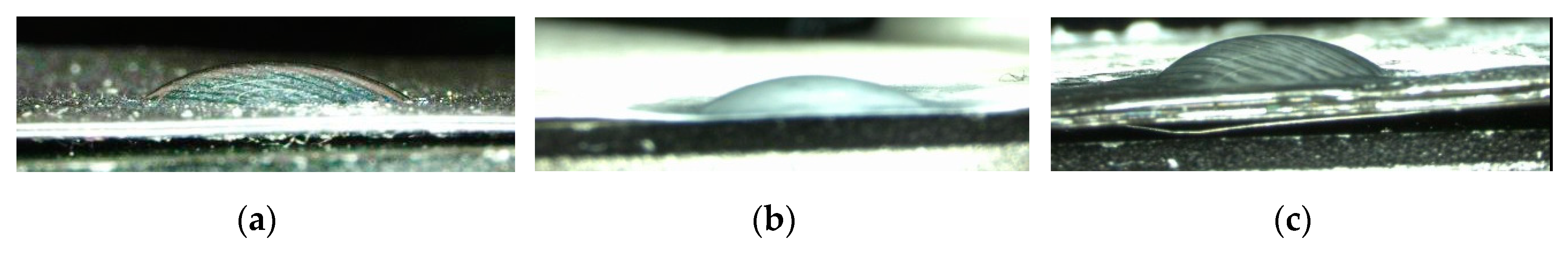
To investigate the hydrophobic properties of the original PAN nanofiber mat, the PLA 3D printing material and the composite contact angle measurements are performed (Figure 7). Since all materials are strongly hydrophilic, the most crucial point is the time between setting the drop on the object under examination and taking the photograph. Contact angles measured approx. 1 s after setting the drop are (34 ± 3)° for PLA, (31 ± 3)° for PAN, and (32 ± 4)° for the PAN/PLA composite surface.
While the contact angles thus do not show a significant difference, it should be mentioned that the drop vanishes slightly faster on the pure PAN nanofiber mat, as compared to the composite, and stays constant for the closed PLA surface. It is observed that spreading of the water inside the nanofiber mat was unidirectional for the pure PAN nanofiber mat, while it was guided along the printing lines in case of the composite. This underlines that care must be taken to position such a composite filter in the optimal orientation with respect to the water flow.
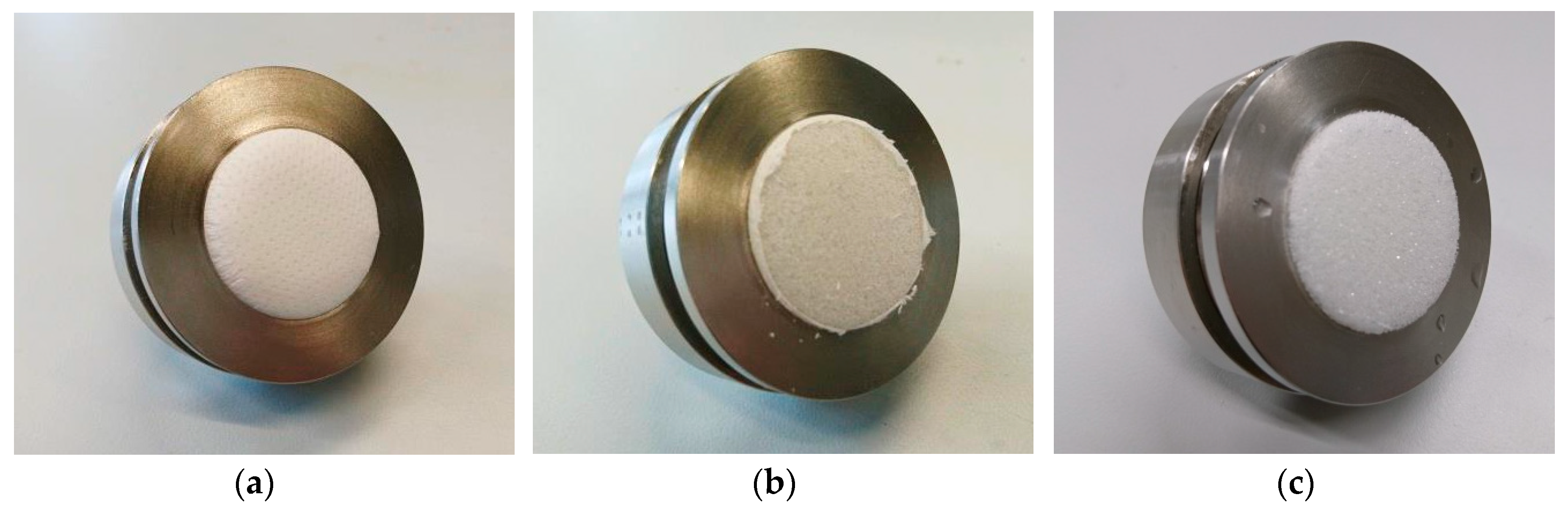
Finally, the mechanical properties of the composites are investigated by a Martindale abrasion test (Figure 8a). This test is usually performed with macroscopic textiles; thus, it destroyed the nanofiber mat in the dry state between 5 and 10 Martindale cycles (Figure 8b) and in the wet state after the first cycle (Figure 8c).
This changed dramatically for the composites surfaces. Figure 9 depicts exemplary images of these surfaces before the tests, after 10, and after 50 Martindale cycles. While after 10 cycles, first protruding areas are abraded, after 50 cycles parts of the nanofiber mats on narrower areas that were not properly fixed there are torn apart; thus, the test was stopped. It should be mentioned that this behavior was quantitatively identical for tests on wet composites. In addition, several areas were still fully coated with the nanofiber mat after 500 Martindale cycles.
These experiments underline that fixing the nanofiber mats by 3D printing on them is generally possible. Nevertheless, further investigations are necessary to optimize the adhesion between both materials over the whole contact area without increasing the danger of touching and thus destroying the nanofiber mat with the 3D printing nozzle.
4. Conclusions
To conclude, we have successfully tested the possibility to prepare composites by 3D printing on raw, stabilized, or carbonized PAN nanofiber mats, thus mechanically stabilizing the nanofiber mats. Optical and chemical examinations revealed that the nanofiber mats were not measurably modified by the 3D printing process. Contact angle examinations did not show significant differences in hydrophilicity, comparing the pure nanofiber mat and the composite surface. Martindale abrasion tests underlined the significantly increased abrasion resistance of the composite.
While in this first proof-of-principle, a full layer was 3D printed on the nanofiber mats, as the composites could be used in filter applications with the liquid flow parallel to them, future experiments have to be conducted to investigate the possibility to print open mesh-like structures on nanofiber mats to also enable utilization in filters through which the liquid flows.
Author Contributions
Conceptualization, T.K.; methodology, T.K. and A.E.; validation, T.K. and A.E.; investigation, T.K., A.M., M.T., L.S., and A.E.; writing—original draft preparation, A.E.; writing—review and editing, all authors.
Funding
This research was funded by the DAAD, funding program number 57440917 – Research Grant and by the Erasmus+ program of the European Union. The APC is funded by the Open Access Publication Fund of Bielefeld University of Applied Sciences and the Deutsche Forschungsgemeinschaft (DFG, German Research Foundation) – 414001623.
Conflicts of Interest
The authors declare no conflict of interest. The funders had no role in the design of the study; in the collection, analyses, or interpretation of data; in the writing of the manuscript; or in the decision to publish the results.
References
- Nakajima, T.; Kajiwara, K.; McIntyre, J.E. Advanced Fiber Spinning Technology; Woodhead Publishing: Sawston, Cambridge, UK, 1994. [Google Scholar]
- Greiner, A.; Wendorff, J.H. Electrospinning: A fascinating method for the preparation of ultrathin fibers. Angew. Chem. Int. Ed. 2007, 46, 5670–5703. [Google Scholar] [CrossRef] [PubMed]
- Li, D.; Xia, Y. Electrospinning of nanofibers: Reinventing the wheel? Adv. Mater. 2004, 16, 1151–1170. [Google Scholar] [CrossRef]
- Rutledge, G.C.; Shin, Y.M.; Brenner, M.P.; Hohman, M.M. Experimental characterization of electrospinning: The electrically forced jet and instabilities. Polymer 2001, 42, 9955–9967. [Google Scholar]
- Döpke, C.; Grothe, T.; Steblinski, P.; Klöcker, M.; Sabantina, L.; Kosmalska, D.; Blachowicz, T.; Ehrmann, A. Magnetic nanofiber mats for data storage and transfer. Nanomaterials 2019, 9, 92. [Google Scholar] [CrossRef]
- Lin, K.-Y.A.; Yang, M.-T.; Lin, J.-T.; Du, Y.C. Cobalt ferrite nanoparticles supported on electrospun carbon fiber as a magnetic heterogeneous catalyst for activating peroxymonosulfate. Chemosphere 2018, 208, 502–511. [Google Scholar] [CrossRef]
- Maver, T.; Kurecic, M.; Smrke, D.M.; Kleinschek, K.S.; Maver, U. Electrospun nanofibrous CMC/PEO as a part of an effective pain-relieving wound dressing. J. Sol.-Gel Sci. Technol. 2016, 79, 475–486. [Google Scholar] [CrossRef]
- Ebrahimi-Hosseinzadeh, B.; Pedram, M.; Hatamian-Zarmi, A.; Salahshour-Kordestani, S.; Rasti, M.; Mokhtari-Hosseini, Z.B.; Mir-Derikvand, M. In vivo evaluation of gelatin/hyaluronic acid nanofiber as Burn-wound healing and its comparison with ChitoHeal gel. Fibers Polym. 2016, 17, 820–826. [Google Scholar] [CrossRef]
- Mamun, A. Review of possible applications of nanofibrous mats for wound dressing. Tekstilec 2019, 62, 89–100. [Google Scholar] [CrossRef]
- Dalton, P.D.; Klinkhammer, K.; Salber, J.; Klee, D.; Möller, M. Direct in vitro electrospinning with polymer melts. Biomacromolecules 2006, 7, 686–690. [Google Scholar] [CrossRef]
- Großerhode, C.; Wehlage, D.; Grothe, T.; Grimmelsmann, N.; Fuchs, S.; Hartmann, J.; Mazur, P.; Reschke, V.; Siemens, H.; Rattenholl, A.; et al. Investigation of microalgae growth on electrospun nanofiber mats. AIMS Bioeng. 2017, 4, 376–385. [Google Scholar] [CrossRef]
- Wehlage, D.; Blattner, H.; Sabantina, L.; Böttjer, R.; Grothe, T.; Rattenholl, A.; Gudermann, F.; Lütkemeyer, D.; Ehrmann, A. Sterilization of PAN/gelatin nanofibrous mats for cell growth. Tekstilec 2019, 62, 78–88. [Google Scholar] [CrossRef]
- Lemma, S.M.; Esposito, A.; Mason, M.; Brusetti, L.; Cesco, S.; Scampicchio, M. Removal of Bacteria and Yeast in Water and Beer by Nylon Nanofibrous Membranes. J. Food Eng. 2015, 137, 1–6. [Google Scholar] [CrossRef]
- Boyraz, E.; Yalcinkaya, F.; Hruza, J.; Maryska, J. Surface-modified nanofibrous PVDF membranes for liquid separation technology. Materials 2019, 12, 2702. [Google Scholar] [CrossRef] [PubMed]
- Yalcinkaya, F.; Siekierka, A.; Bryjak, M. Preparation of fouling-resistant nanofibrous composite membranes for separation of oily wastewater. Polymers 2017, 9, 679. [Google Scholar] [CrossRef] [PubMed]
- Lv, D.; Wang, R.; Tang, G.S.; Mou, Z.P.; Lei, J.D.; Han, J.Q.; de Smedt, S.; Xiong, R.H.; Huang, C.B. Ecofriendly Electrospun Membranes Loaded with Visible-Light-Responding Nanoparticles for Multifunctional Usages: Highly Efficient Air Filtration, Dye Scavenging, and Bactericidal Activity. ACS Appl. Mater. Interfaces 2019, 11, 13. [Google Scholar]
- Zhu, M.M.; Han, J.Q.; Wang, F.; Shao, W.; Xiong, R.H.; Zhang, Q.; Pan, H.; Yang, Y.; Samal, S.K.; Zhang, F.; et al. Electrospun nanofiber membranes for effective air filtration. Macromol. Mater. Eng. 2017, 302, 1600353–1600380. [Google Scholar] [CrossRef]
- Lv, D.; Zhu, M.M.; Jiang, Z.C.; Jiang, S.H.; Zhang, Q.; Xiong, R.H.; Huang, C.B. Green electrospun nanofibers and their application in air filtration. Macromol. Mater. Eng. 2018, 303, 1800336–1800354. [Google Scholar] [CrossRef]
- Huang, Z.-M.; Zhang, Y.Z.; Ramakrishna, S.; Lim, C.T. Electrospinning and mechanical characterization of gelatin nanofibers. Polymer 2004, 45, 5361–5368. [Google Scholar] [CrossRef]
- Fan, L.; Yan, J.; He, H.; Deng, N.; Zhao, Y.; Kang, W.; Cheng, B. Electro-blown spun PS/PAN fibrous membrane for highly efficient oil/water separation. Fibers Polym. 2017, 18, 1988–1994. [Google Scholar] [CrossRef]
- Roche, R.; Yalcinkaya, F. Electrospun polyacrylonitrile nanofibrous membranes for point-of-use water and air cleaning. ChemistryOpen 2019, 8, 97–103. [Google Scholar] [CrossRef]
- Wirth, E.; Sabantina, L.; Weber, M.; Finsterbusch, K.; Ehrmann, A. Preliminary study of ultrasonic welding as a joining process for electrospun nanofiber mats. Nanomaterials 2018, 8, 746. [Google Scholar] [CrossRef] [PubMed]
- Charles, L.F.; Shaw, M.T.; Olson, J.R.; Wei, M. Fabrication and mechanical properties of PLLA/PCL/HA composites via a biomimetic, dip coating, and hot compression procedure. J. Mater. Sci. Mater. Med. 2010, 21, 1845–1854. [Google Scholar] [CrossRef] [PubMed]
- Roche, R.; Yalcinkaya, F. Incorporation of PVDF nanofibre multilayers into functional structure for filtration applications. Nanomaterials 2018, 8, 771. [Google Scholar] [CrossRef] [PubMed]
- Fu, Q.S.; Lin, G.; Chen, X.D.; Yu, Z.X.; Yang, R.S.; Li, M.T.; Zeng, X.G.; Chen, J. Mechanically Reinforced PVdF/PMMA/SiO2 Composite Membrane and Its Electrochemical Properties as a Separator in Lithium-Ion Batteries. Energy Technol. 2018, 6, 144–152. [Google Scholar] [CrossRef]
- Qin, X.-H.; Wang, S.-Y. Electrospun nanofibers from crosslinked poly(vinyl alcohol) and its filtration efficiency. Appl. Polym. Sci. 2008, 109, 951–956. [Google Scholar] [CrossRef]
- Kozior, T.; Kundera, C. Surface Texture of Models Manufactured by FDM Technology. AIP Conf. Proc. 2018, 2017, 020011. [Google Scholar]
- Kundera, C.; Martsynkowskyy, V.; Gudkov, S.; Kozior, T. Effect of rheological parameters of elastomeric ring materials on dynamic of face seals. Procedia Eng. 2017, 177, 307–313. [Google Scholar] [CrossRef]
- Uysal, R.; Stubbs, J.B. A new method of printing multi-material textiles by fused deposition modelling (FDM). Tekstilec 2019, 62, 248–257. [Google Scholar]
- Calvo, J.O.; Martin, A.C.; Ferradas, M.I.R.; Morcillo, P.L.F.; Munoz, L.M.; Camo, P.M. Additive manufacturing on textiles with low-cost extrusion devices: Adhesion and deformation properties. Dyna 2019, 64, 8893. [Google Scholar]
- Grimmelsmann, N.; Lutz, M.; Korger, M.; Meissner, H.; Ehrmann, A. Adhesion of 3D printed material on textile substrates. Rapid Prototyp. J. 2018, 24, 166–170. [Google Scholar] [CrossRef]
- Sanatgar, R.H.; Campagne, C.; Nierstraz, V. Investigation of the adhesion properties of direct 3D printing of polymers and nanocomposites on textiles: Effect of FDM printing process parameters. Appl. Surf. Sci. 2017, 403, 551–563. [Google Scholar] [CrossRef]
- Malengier, B.; Hertleer, C.; Cardon, L.; van Langenhove, L. 3D Printing on Textiles: Testing of Adhesion. J. Fash. Technol. Text. Eng. 2017, S4, 013. [Google Scholar]
- Mpofu, N.S.; Wasiagi, J.I.; Nkiwane, L.C.; Njuguna, D. Use of regression to study the effect of fabric parameters on the adhesion of 3D printed PLA polymer onto woven fabrics. Fash. Text. 2019, 6, 24. [Google Scholar] [CrossRef]
- Pei, E.; Shen, J.; Watling, J. Direct 3D printing of polymers onto textiles: Experimental studies and applications. Rapid Prototyp. J. 2015, 21, 556–571. [Google Scholar] [CrossRef]
- Korger, M.; Bergschneider, J.; Lutz, M.; Mahltig, B.; Finsterbusch, K.; Rabe, M. Possible applications of 3D printing technology on textile substrates. IOP Conf. Ser. Mater. Sci. Eng. 2016, 141, 012011. [Google Scholar] [CrossRef]
- Kozior, T.; Döpke, C.; Grimmelsmann, N.; Juhász Junger, I.; Ehrmann, A. Influence of fabric pretreatment on adhesion of 3D printed material on textile substrates. Adv. Mech. Eng. 2018, 10. [Google Scholar] [CrossRef]
- Unger, L.; Scheideler, M.; Meyer, P.; Harland, J.; Görzen, A.; Wortmann, M.; Dreyer, A.; Ehrmann, A. Increasing Adhesion of 3D Printing on Textile Fabrics by Polymer Coating. Tekstilec 2018, 61, 265–271. [Google Scholar] [CrossRef]
- Yeo, M.; Kim, G. Nano/microscale topographically designed alginate/PCL scaffolds for inducing myoblast alignment and myogenic differentiation. Carbohydr. Polym. 2019, 223, 115041. [Google Scholar] [CrossRef]
- Rajzer, I.; Kurowska, A.; Jablonski, A.; Jatteau, S.; Sliwka, M.; Ziabka, M.; Menaszek, E. Layered gelatin/PLLA scaffolds fabricated by electrospinning and 3D printing- for nasal cartilages and subchondral bone reconstruction. Mater. Des. 2018, 155, 297–306. [Google Scholar] [CrossRef]
- Naghieh, S.; Foroozmehr, E.; Badrossamay, M.; Kharaziha, M. Combinational processing of 3D printing and electrospinning of hierarchical poly(lactic acid)/gelatin-forsterite scaffolds as a biocomposite: Mechanical and biological assessment. Mater. Des. 2017, 133, 128–135. [Google Scholar] [CrossRef]
- Ngadiman, N.H.A.; Yusof, N.M.; Idris, A.; Fallahiarezoudar, E.; Kurniawan, D. Novel Processing Technique to Produce Three Dimensional Polyvinyl Alcohol/Maghemite Nanofiber Scaffold Suitable for Hard Tissues. Polymers 2018, 10, 353. [Google Scholar] [CrossRef] [PubMed]
- Chen, W.M.; Xu, Y.; Liu, Y.Q.; Wang, Z.X.; Li, Y.Q.; Jiang, G.N.; Mo, X.M.; Zhou, G.D. Three-dimensional printed electrospun fiber-based scaffold for cartilage regeneration. Mater. Des. 2019, 179, 107886. [Google Scholar] [CrossRef]
- Mendoza-Buenrostro, C.; Lara, H.; Rodriguez, C. Hybrid fabrication of a 3D printed geometry embedded with PCL nanofibers for tissue engineering applications. Procedia Eng. 2015, 110, 128–134. [Google Scholar] [CrossRef]
- Sabantina, L.; Rodríguez-Cano, M.Á; Klöcker, M.; García-Mateos, F.J.; Ternero-Hidalgo, J.J.; Mamun, A.; Beermann, F.; Schwakenberg, M.; Voigt, A.-L.; Rodríguez-Mirasol, J.; et al. Fixing PAN Nanofiber Mats during Stabilization for Carbonization and Creating Novel Metal/Carbon Composites. Polymers 2018, 10, 735. [Google Scholar] [CrossRef] [PubMed]
- Grothe, T.; Wehlage, D.; Böhm, T.; Remche, A.; Ehrmann, A. Needleless Electrospinning of PAN Nanofibre Mats. Tekstilec 2017, 60, 290–295. [Google Scholar] [CrossRef]
- Sabantina, L.; Böttjer, R.; Wehlage, D.; Grothe, T.; Klöcker, M.; García-Mateos, F.J.; Rodríguez-Mirasol, J.; Cordero, T.; Ehrmann, A. Morphological study of stabilization and carbonization of polyacrylonitrile/TiO2 nanofiber mats. J. Eng. Fibers Fabr. 2019, 14, 77. [Google Scholar] [CrossRef]
- Spahiu, T.; Al-Arabiyat, M.; Martens, Y.; Ehrmann, A.; Piperi, E.; Shehi, E. Adhesion of 3D printing polymers on textile fabrics for garment production. IOP Conf. Ser. Mater. Sci. Eng. 2018, 459, 012065. [Google Scholar] [CrossRef]
- Grothe, T.; Sabantina, L.; Klöcker, M.; Juhász Junger, I.; Döpke, C.; Ehrmann, A. Wet relaxation of electrospun nanofiber mats. Technologies 2019, 7, 23. [Google Scholar] [CrossRef]
- Sabantina, L.; Klöcker, M.; Wortmann, M.; Rodríguez-Mirasol, J.; Cordero, T.; Moritzer, E.; Finsterbusch, K.; Ehrmann, A. Stabilization of polyacrylonitrile nanofiber mats obtained by needleless electrospinning using dimethyl sulfoxide as solvent. J. Ind. Text. 2019. online first. [Google Scholar] [CrossRef]
- Suarez-Franco, J.L.; Vázquez-Vázquez, F.C.; Pozoz-Guillen, A.; Montesinos, J.J.; Alvarez-Fregoso, O.; Alvarez-Perez, M.A. Influence of diameter of fiber membrane scaffolds on the biocompatibility of hPDL mesenchymal stromal cells. Dental Mater. J. 2018, 37, 465–473. [Google Scholar] [CrossRef]
- Rocca-Smith, J.R.; Lagorce-Tachon, A.; Iaconelli, C.; Bellat, J.P.; Marcuzzo, E.; Sensidoni, A.; Piasente, F.; Debeaufort, F.; Karbowiak, T. How high pressure CO2 impacts PLA film properties. eXPRESS Polym. Lett. 2017, 11, 320–333. [Google Scholar] [CrossRef]
- Silva Murakami, L.M.; Baracho Azevedo, J.; Diniz, M.F.; Silva, L.M.; de Cássia Lazzarini Dutra, R. Characterization of additives in NR formulations by TLC-IR (UATR). Polímeros 2018, 28, 205–214. [Google Scholar] [CrossRef]
- Palacio, J.; Orozco, V.H.; López, B.L. Effect of the molecular weight on the physicochemical properties of poly(lactic acid) nanoparticles and on the amount of ovalbumin adsorption. J. Braz. Chem. Soc. 2011, 22, 2304–2311. [Google Scholar] [CrossRef] [Green Version]
- Mólnar, K.; Szolnoki, B.; Toldy, A.; Vas, L.M. Thermochemical stabilization and analysis of continuously electrospun nanofibers. J. Therm. Anal. Calorim. 2014, 117, 1123–1135. [Google Scholar] [CrossRef]
- Gergin, I.; Ismar, E.; Sarac, A.S. Oxidative stabilization of polyacrylonitrile nanofibers and carbon nanofibers containing graphene oxide (GO): A spectroscopic and electrochemical study. Beilstein J. Nanotechnol. 2017, 8, 1616–1628. [Google Scholar] [CrossRef] [PubMed]
- Cipriani, E.; Zanetti, M.; Bracco, P.; Brunella, V.; Luda, M.P.; Costa, L. Crosslinking and carbonization processes in PAN films and nanofibers. Polym. Degrad. Stab. 2016, 123, 178–188. [Google Scholar] [CrossRef]
- Arshad, S.N.; Naraghi, M.; Chasiotis, I. Strong carbon nanofibers from electrospun polyacrylonitrile. Carbon 2011, 49, 1710–1719. [Google Scholar] [CrossRef]
Figure 1.
3D printing with fused deposition modeling (FDM) technology on a polyacrylonitrile (PAN) nanofiber mat. The printing polymer PLA (here green) is delivered as a filament into the nozzle in a molten state and placed on the nanofiber mat.
Figure 1.
3D printing with fused deposition modeling (FDM) technology on a polyacrylonitrile (PAN) nanofiber mat. The printing polymer PLA (here green) is delivered as a filament into the nozzle in a molten state and placed on the nanofiber mat.
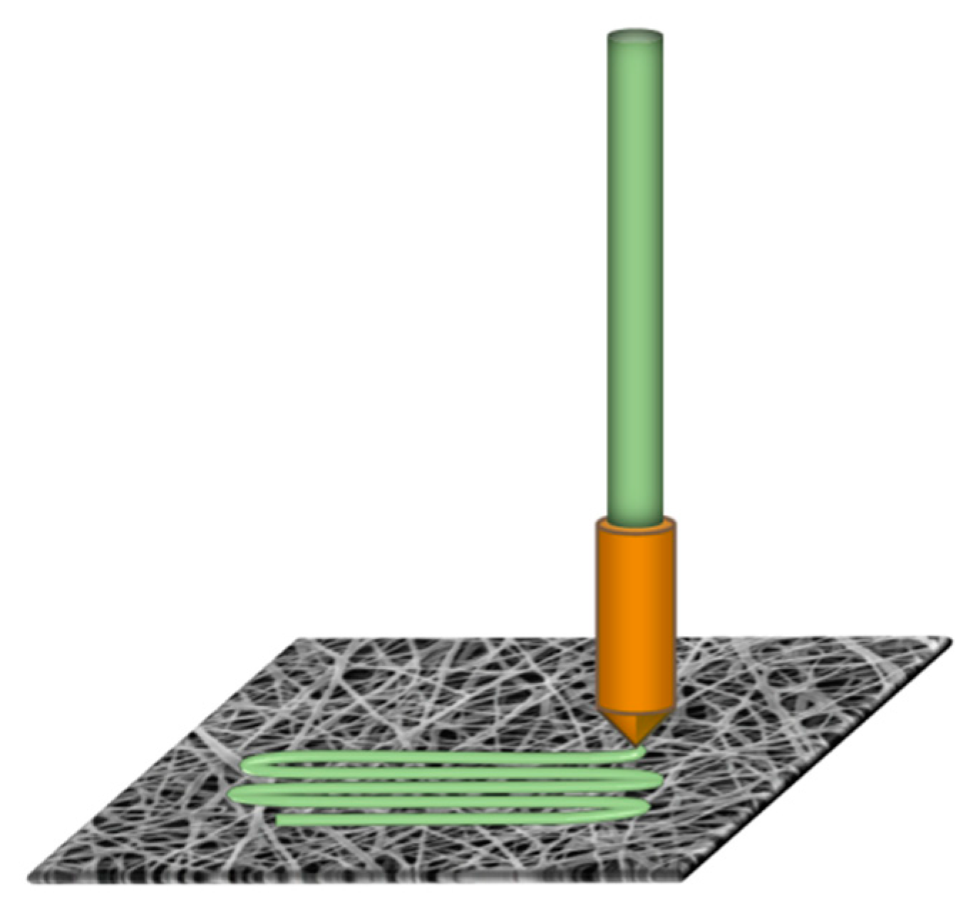
Figure 2.
3D printing squares of dimensions 40 mm × 40 mm on nanofiber mats: (a) rough surface for a too large distance between nanofiber mat and printing nozzle and (b) composite strongly sticking on the double-sided adhesive tape used for gluing the nanofiber mat over its entire area.
Figure 2.
3D printing squares of dimensions 40 mm × 40 mm on nanofiber mats: (a) rough surface for a too large distance between nanofiber mat and printing nozzle and (b) composite strongly sticking on the double-sided adhesive tape used for gluing the nanofiber mat over its entire area.
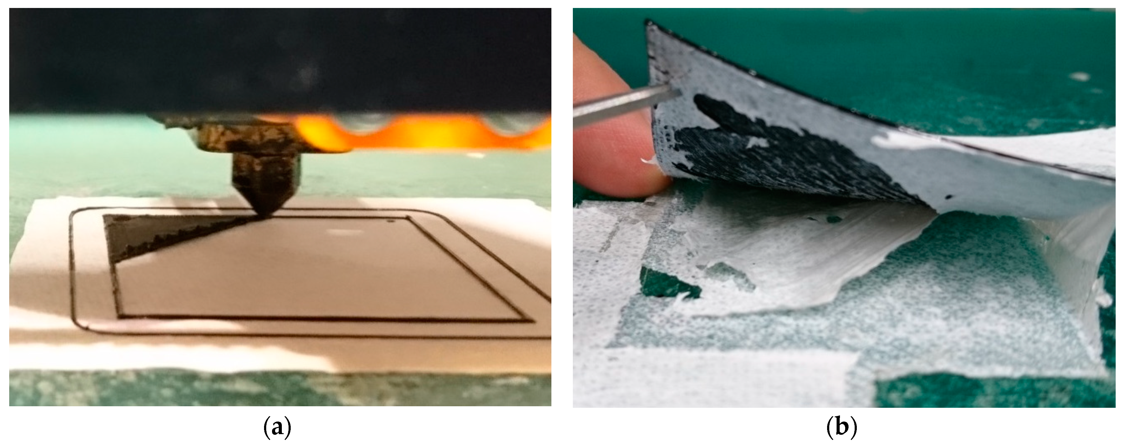
Figure 3.
3D printing squares of dimensions 40 mm × 40 mm on nanofiber mats previously dipped in soap water: (a) rough surface for a too large distance between nanofiber mat and printing nozzle; (b) 3D printed layer with uneven surface and even several not closed areas near the diagonal, i.e., along the longest lines, due to a too large distance between nozzle and nanofiber mat.
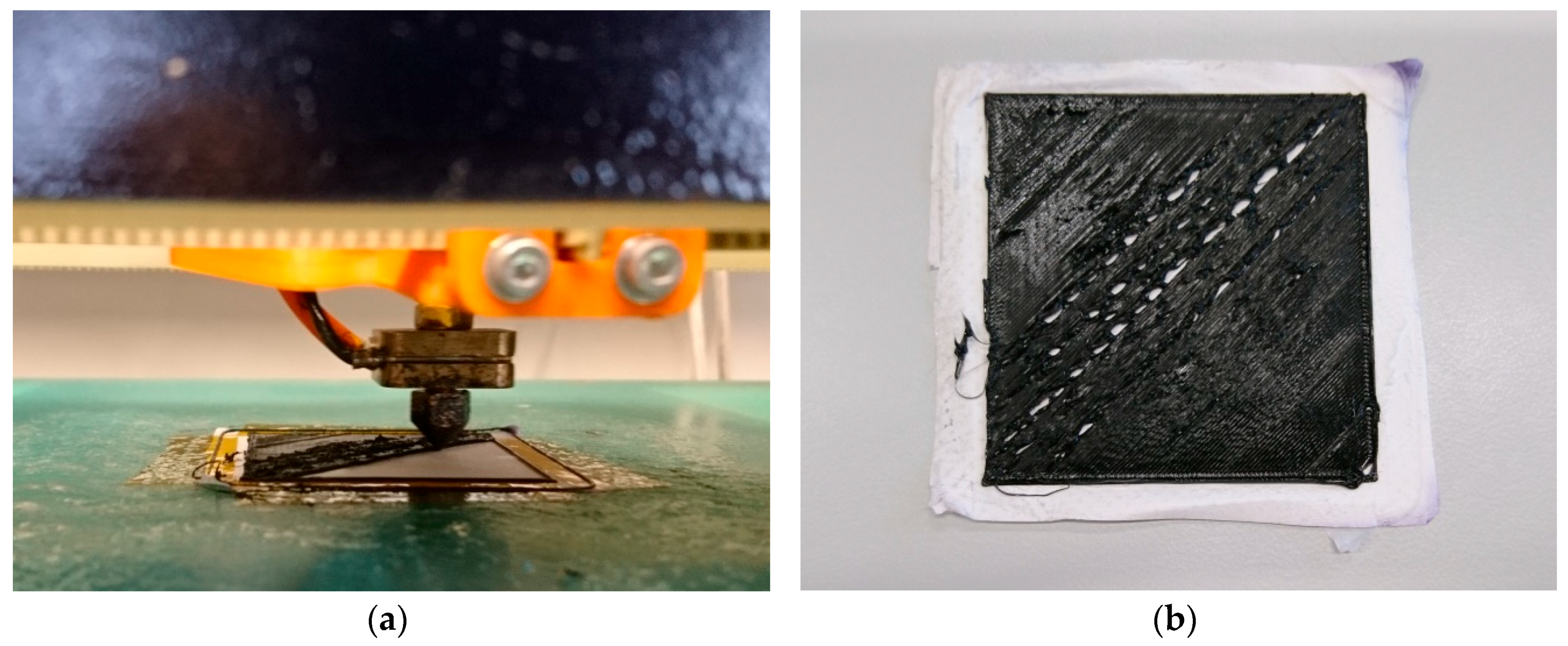
Figure 4.
Confocal laser scanning microscope (CLSM) images of polyacrylonitrile (PAN) nanofiber mats: (a) pure PAN (electrospun with 80 kV), (b) pure PAN (electrospun with 80 kV) after printing on the other side of the nanofiber mat, (c) carbonized PAN (electrospun with 50 kV), and (d) carbonized PAN (electrospun with 50 kV) after printing on the other side of the nanofiber mat.

Figure 5.
Optical microscopic images of PAN nanofiber mats after 3D printing and being peeled off the printed polymer: (a) PAN on aluminum (electrospun with 80 kV)—average situation; (b) PAN on aluminum (electrospun with 80 kV)—thinnest nanofiber “coating” found on all samples; (c) stabilized PAN (electrospun with 80 kV); and (d) carbonized PAN (electrospun with 50 kV).
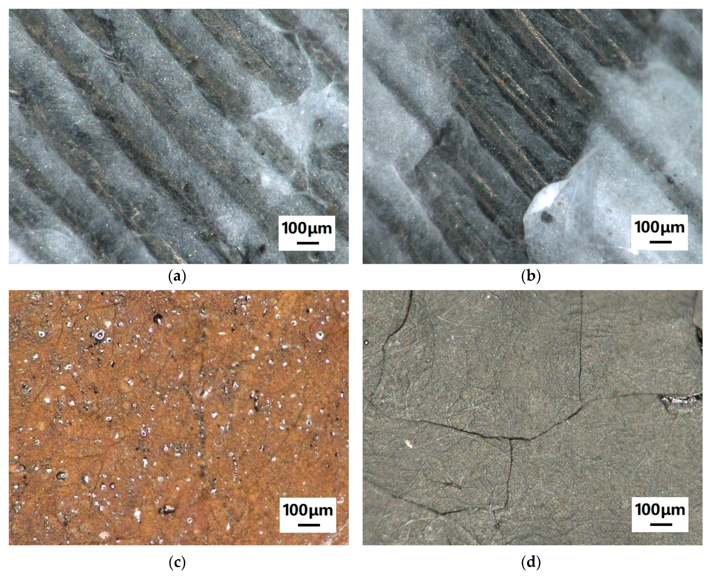
Figure 6.
FTIR spectra of (a) pure PAN and pure poly(lactic acid) (PLA) for comparison, with some prominent peaks marked and (b) PAN nanofiber mats in raw, stabilized, and carbonized state on PLA.
Figure 6.
FTIR spectra of (a) pure PAN and pure poly(lactic acid) (PLA) for comparison, with some prominent peaks marked and (b) PAN nanofiber mats in raw, stabilized, and carbonized state on PLA.
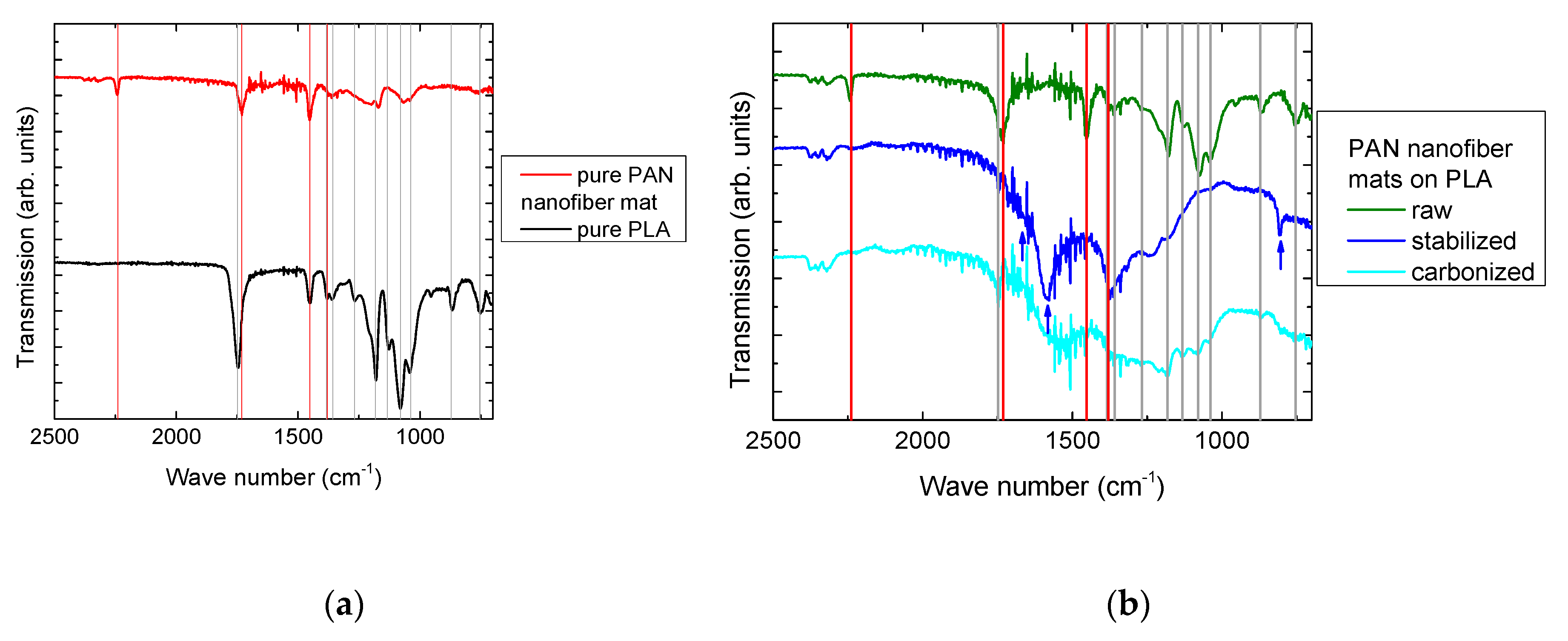
Figure 7.
Contact angles, investigated by dropping 15 µL of distilled water on (a) an FDM-printed PLA layer, (b) an electrospun PAN nanofiber mat, and (c) a PAN/PLA composite prepared as described in this article.
Figure 7.
Contact angles, investigated by dropping 15 µL of distilled water on (a) an FDM-printed PLA layer, (b) an electrospun PAN nanofiber mat, and (c) a PAN/PLA composite prepared as described in this article.

Figure 8.
Electrospun nanofiber mat in Martindale abrasion test holder, (a) before the test, (b) after 10 cycles in dry state, and (c) after one cycle in wet state.
Figure 8.
Electrospun nanofiber mat in Martindale abrasion test holder, (a) before the test, (b) after 10 cycles in dry state, and (c) after one cycle in wet state.

Figure 9.
Composite surface after Martindale abrasion tests, (a) before the test, (b) after 10 cycles in dry state, and (c) after 50 cycles in dry state.
Figure 9.
Composite surface after Martindale abrasion tests, (a) before the test, (b) after 10 cycles in dry state, and (c) after 50 cycles in dry state.
© 2019 by the authors. Licensee MDPI, Basel, Switzerland. This article is an open access article distributed under the terms and conditions of the Creative Commons Attribution (CC BY) license (http://creativecommons.org/licenses/by/4.0/).
Share and Cite
MDPI and ACS Style
Kozior, T.; Trabelsi, M.; Mamun, A.; Sabantina, L.; Ehrmann, A. Stabilization of Electrospun Nanofiber Mats Used for Filters by 3D Printing. Polymers 2019, 11, 1618. https://doi.org/10.3390/polym11101618
AMA Style
Kozior T, Trabelsi M, Mamun A, Sabantina L, Ehrmann A. Stabilization of Electrospun Nanofiber Mats Used for Filters by 3D Printing. Polymers. 2019; 11(10):1618. https://doi.org/10.3390/polym11101618
Chicago/Turabian StyleKozior, Tomasz, Marah Trabelsi, Al Mamun, Lilia Sabantina, and Andrea Ehrmann. 2019. "Stabilization of Electrospun Nanofiber Mats Used for Filters by 3D Printing" Polymers 11, no. 10: 1618. https://doi.org/10.3390/polym11101618
Note that from the first issue of 2016, this journal uses article numbers instead of page numbers. See further details here.