Article

Multi-Wavelength Filters of Templated Blue Phase Liquid Crystal

National Engineering Lab for TFT-LCD Materials and Technologies, Department of Electronic Engineering, Shanghai Jiao Tong University, Shanghai 200240, China
*
Author to whom correspondence should be addressed.
Crystals 2019, 9(9), 451; https://doi.org/10.3390/cryst9090451
Submission received: 10 July 2019 / Revised: 8 August 2019 / Accepted: 28 August 2019 / Published: 30 August 2019
(This article belongs to the Special Issue Liquid Crystal Optics and Physics: Recent Advances and Prospects)

Abstract

:
The multi-wavelength filters in the visible light band using the blue phase liquid crystal (BPLC) template was investigated. A multi-layer templated BPLC (T-BPLC) filter without intermediate dielectric layers was fabricated, which may reflect multi-wavelength in one filter. Compared with the cholesteric liquid crystal (CLC) filter, the T-BPLC filter may get a much narrower reflection bandwidth (<15 nm), show better angular stability of incident light, and have a more stable wavelength and bandwidth with a temperature shift. Furthermore, the central wavelength and bandwidth can be easily controlled by the fabrication process and the optimization of the material concentration. When the incident angle varies, the shift of the center wavelength of the T-BPLC filter is much smaller than that of the CLC filter. The multi-wavelength filter shows a potential application in color filters and high-density wavelength division multiplexed networks.

1. Introduction

Optical filters, including Fabry–Perot filters [1,2], thin film optical filters [3], waveguide filters [4], and Mach-Zehnder interferometer filters [5], have been widely applied in optical communication and display. The cholesteric liquid crystals (CLCs) have been widely applied in the optical filters due to the Bragg reflection with a helical structure [6,7,8,9,10]. The central wavelength and bandwidth of CLC filters can be easily tuned by thermal or electrical modulation. Huang reported a bandwidth-variable tunable filter based on the thermal effect [11]. Tondiglia et al. demonstrated an electrically induced broad bandwidth filter in polymer stabilized CLCs [12]. However, the bandwidth of CLC filters is too broad to apply in a multi-wavelength filter and the fabrication process of multi-film CLC filters is too complex [13,14]. Furthermore, the central wavelength of CLC filters will shift after the refilling process by a CLC template [15].
The blue phase liquid crystal (BPLC) usually exists between the isotropic phase and chiral nematic phase, in a narrow temperature range of 1–2 °C. By stabilizing the disclination lines with polymer networks, the temperature range of BPLCs can be broadened to more than 60 °C [16,17]. On the other hand, after refilling an achiral nematic liquid crystal (LC) into the polymer template, the 3-D helical structure of BPLC can be reconstructed, and the thermal stability of the blue phase can be improved [18,19,20,21]. With good thermal stability, the BPLCs have attracted more interest for the applications in filter [22], display [23] and lasing [24] due to the sub-millisecond response time, macro optical isotropic status, and self-assembled photonic crystal structures on the order of visible wavelength. In this paper, a narrow bandwidth multi-wavelength filter is proposed based on templated BPLCs (T-BPLCs) in the visible band, which can realize multi-layer LC devices without the intermediate layer and reflect multiple wavelengths at the same time. Compared with CLC filters, T-BLPC filters show a narrower reflection bandwidth, better angular stability of incident light, and a more stable central wavelength and bandwidth. The central wavelength and bandwidth of the filter can be easily controlled by the fabrication process and the optimization of the material concentration.

2. Materials and Fabrication Process of BPLC Templates

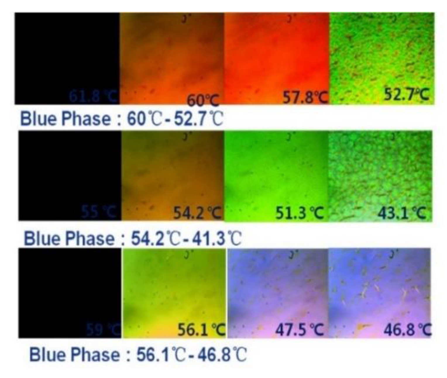
2.1. Materials Preparation

In order to demonstrate the different reflection spectrum of polymer-stabilized BPLCs (PS-BPLCs) and T-BPLCs, the PS-BPLCs were prepared in our experiment. The PS-BPLC mixtures were composed of a positive nematic liquid crystal (HBG98, Jiangsu Hecheng Display Technology Co., Ltd. (HCCH), Jiangsu, China), a chiral dopant (R5011, HCCH), a cross-linking agent (C3M), an ultraviolet (UV) curable monomer (TMPTA, HCCH), and a photo-initiator (IRG184, HCCH). To obtain the BPLC template, the material system consists of 84.3 wt% of HBG98, 3.42 wt% of chiral agent R5011 (HCCH), 5 wt% of ultraviolet (UV) curable monomer (TMPTA, HCCH), 7 wt% of cross-linker agent (C3M, HCCH), and 0.1 wt% of photo-initiator (IRG184, HCCH). When preparing the material, we have to make sure the composite of BPLC is extremely accurate and the temperature control is pretty stable. Otherwise, the central wavelength of the red, green, and blue color templates would coincide and affect each other. As shown in Table 1, three kinds of chiral dopant concentration for PS-BPLC materials were designed to get reflection central wavelengths of red, green, and blue colors.

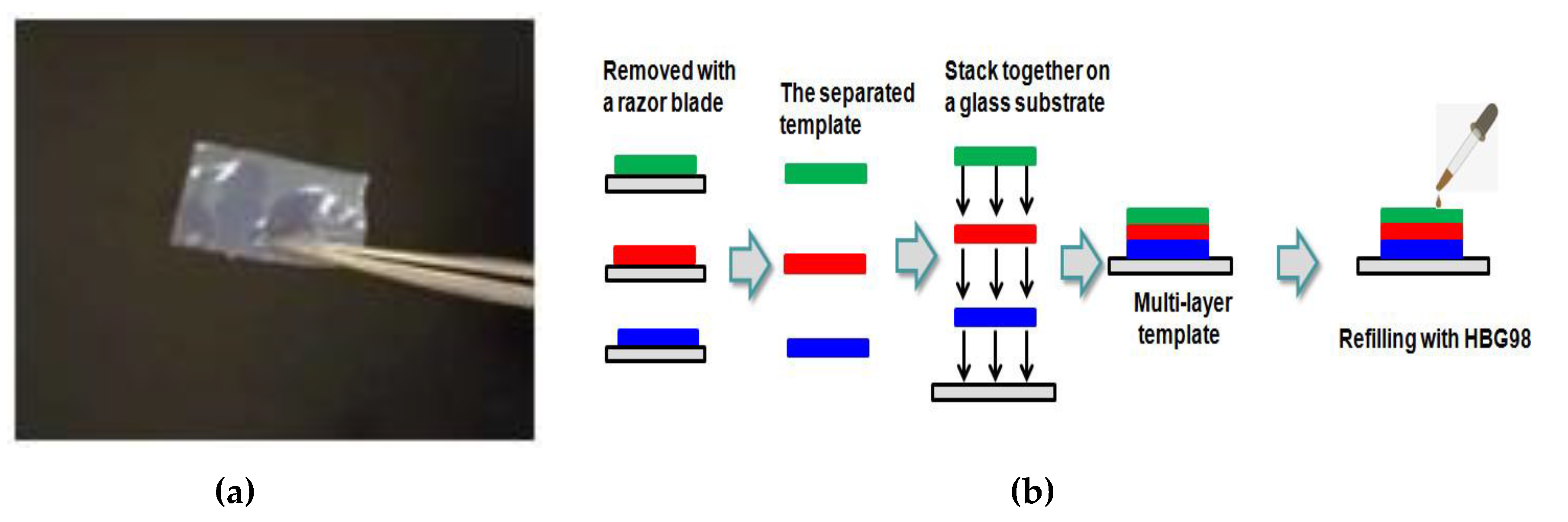
2.2. Fabrication Process of T-BPLC

First, the materials in Table 1 were fully stirred on a constant temperature magnetic stirrer (524 G, Shanghai Messrs Instrument, shanghai, China) for about 10 min until the material appears as clear and transparent liquid. Then, the precursor was capillary into the cell with alignment treatment. The phase transition process was observed under a polarized optical microscope (POM, XPL-30TF, Shanghai WeiTu Optics & Electron Technology Co., Ltd., Shanghai, China) on the temperature controller (HCS302, Instec Co., Boulder, CO, USA). Lastly, the PS-BPLC can be fabricated by ultraviolet exposure (wavelength: 365 nm, exposure time: 8 min, exposure intensity: 3 mW/cm2).
To obtain the BPLC template, the upper and lower glass substrates of the cell are separated and the PS-BPLC was attached to one of the glass substrates. Then, we put the glass substrate with PS-BPLC in ethanol for about 10 min to wash out LC, chiral dopant, crosslinker, and the photo-initiator. After that, the glass substrate with the template was placed on the temperature controller with 50 °C for 5 min to remove the residual ethanol. In the experiment, we have to extract the film within 3 min because, if the ethanol in the polymer template is completely evaporated, the template becomes very crisp and easy to break. In order to facilitate the stripping operation, the thickness of each polymer template is 30 um. Then the polymer template can be separated from the glass substrate with a razor blade, as shown in Figure 1a. After the templates of a different reflection wavelength were laminated without intermediate layers, a nematic LC HBG98 (Jiangsu Hecheng Display Technology Co., Ltd., Jiangsu, China) was refilled into the multi-layer template to reconstruct the different BPLCs. Lastly, the multi-wavelength T-BPLC filters were fabricated, as illustrated in Figure 1b.

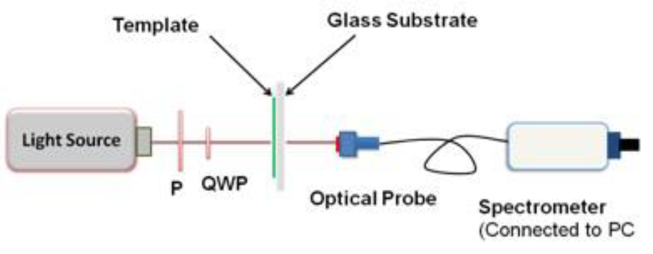
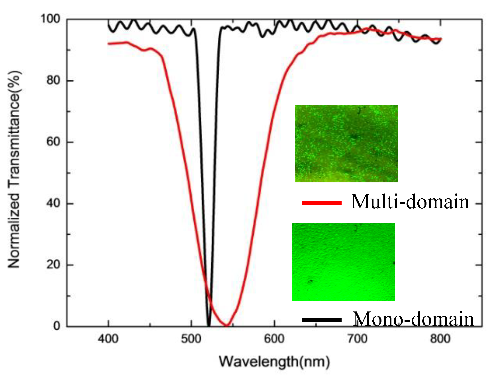
3. Measurement and Analysis

The measurement system to analyze the spectral characteristics of the BPLC filters was shown in Figure 2. A tungsten halogen lamp was used as the unpolarized light source covering the visible region. The unpolarized light source was incident on the sample, the signals passing through a polarizer, and a quarter-wave plate. The signals were received by an optical fiber, which is connected by a spectrometer.
BPLCs usually show a multi-domain structure due to the different initial states of LC molecules. This leads to scattering characteristics and the bandwidth of its reflection wavelength is relatively wide. In order to obtain a narrow bandwidth of blue phase liquid crystal devices, a single crystal blue phase liquid crystal or mono-domain blue phase liquid crystal can be used. Due to the complex preparation process and poor stability of a single crystal [25], the surface orientation method [26] was used to induce mono-domain BPLCs. Figure 3 shows the polarizing microscope images of PS-BPLC of the blue, green, and red color. As shown in Figure 3, BPLC of the red texture (650 nm) appeared between 60 and 52.7 °C, BPLC of the green texture (520 nm) appeared between 54.2 and 41.3 °C, and BPLC of the blue texture (450 nm) appeared between 56.1 and 46.8 °C.
As shown in Figure 4, the variance of T-BPLC and T-CLC is on the same order of magnitude. Therefore, we apply a normalized method to handle the transmittance. Take the difference between the maximum and the minimum of transmittance as the denominator, and the difference between the initial and the minimum of transmittance as the numerator. We can calculate the normalized transmittance. With the alignment layer, the mono-domain BPLC can be achieved and the full width at half maximum (FWHM) of the mono-domain BPLC reflection spectrum is about 11 nm, which is much narrower than that of the multi-domain BPLC at about 85 nm. By comparing the mono-domain and multi-domain BPLC, we find the mono-domain BPLC has a narrower reflection bandwidth. We use the anti-parallel alignment cell to obtain the mono-domain BPLC. Therefore, we use the mono-domain BPLCs for the multi-wavelength filters.
With the different chiral dopant concentrations shown in Table 1, the reflection spectrums of PS-BPLCs and T-BPLCs with red, green, and blue colors were achieved by the measurement system shown in Figure 1. As illustrated in Figure 5, the reflection peaks of PS-BPLCs with 3.6, 3.42 and 3.13 wt% of chiral dopant are 455, 520 and 650 nm, which show blue, green, and red, respectively. The full widths at half maximum of the reflection spectrum in PS-BPLCs are about 12 nm for blue, 14 nm for green, and 18 nm for red colors, respectively. After the washout and refilling process, the reflection peaks of T-BPLCs are 457 nm for blue, 525 nm for green, and 655 nm for red colors, respectively. The FWHMs of the reflection spectrum in T-BPLCs are 12 nm for blue, 14 nm for green, and 16 nm for red colors, respectively. As we can see, the reflection peak and FWHM of the T-BPLCs almost have no change after the washout and refilling process. Thus, the T-BPLCs show perfect repeatability and process stability. Compared with prior arts whose sandwiched layers need intermedia [13], our multi-layer template filters have no intermedia. Since the template separated from the LC cell is malleable and ductile, we can stack them tightly and seamlessly. It is not necessary to put two more glasses to separate the red, green, and blue LC.
In order to investigate the influence of temperature stability of T-BPLCs, we compared the variations of the central wavelength and bandwidth between T-BPLC and template CLC (T-CLC) at different temperatures. The T-CLC mixtures were composed of 98 wt% of positive nematic liquid crystal BPH006 (Jiangsu Hecheng Display Technology Co., Ltd., Jiangsu, China) and 2 wt% of chiral dopant R5011 (Jiangsu Hecheng Display Technology Co., Ltd., Jiangsu, China). As shown in Figure 6a, when the temperature is 30 °C, the central wavelength of T-BPLC is 520 nm and the wavelength of FWHM is 30 nm. With the increase of the temperature, the central wavelength and the FWHM of T-BPLC have no change. Regarding the temperature characteristics of CLC shown in Figure 6b, when the temperature is 30 °C, the central wavelength of T-CLCs is 580 nm and the wavelength of FWHM is 64 nm. With the increase of the temperature to 60 °C, the central wavelength of T-CLC shifts to 550 nm and the wavelength of FWHM increases to 74 nm. Therefore, we may say the temperature stability of the T-BPLCs is better than that of the T-CLCs.
In order to investigate the influence of the incident angle on the central wavelength of T-BPLCs, we measured the variations of the central wavelength of T-BPLCs at different incident angles. In the region close to the glass substrate, the LC molecules are arranged in the horizontal direction due to the anti-parallel alignment cell. It is the incomplete optical isotropy that eventually leads to angle dependence. As shown in Figure 7a, when the incident angle is at 0°, the central wavelength of T-BPLCs is 520 nm. With an increase of the angle, the central wavelength of T-BPLCs has a blue shift. As the angle increases to 60°, the central wavelength shifts to 461 nm.
While the incident angle is 0°, the central wavelength of T-CLC is 582 nm, as shown in Figure 7b. With the increase of the incident angle, the central wavelength also shows a blue shift. When the incident angle reaches 60°, the central wavelength shifts to 462 nm. As the wavelength shift from the incident angle 0 to 60° of the T-BPLC filter, which is 59 nm, is much less than that of the T-CLC filter, which is 120 nm. We may say the angular stability of the T-BPLC is better than that of the T-CLCs.
After refilling the achiral LC into the multi-layer T-BPLC templates, four kinds of the multi-wavelength filters can be achieved, which include red/green, red/blue, green/blue, and red/green/blue. As shown in Figure 8, the reflection peaks of red/green filter are 522 and 649 nm, with the FWHM of 11 and 12 nm, respectively. The reflection peaks of the blue/green filter are 455 and 531 nm, with the FWHM of 12 and 14 nm, respectively. The reflection peaks of blue/red filters are 455 and 654 nm, with the FWHM of 12 and 16 nm, respectively. The reflection peaks of the red/green/blue filter are 455, 522 and 654 nm, with FWHM of 11, 10 and 11 nm, respectively.
No matter the dual layer of T-BPLC filters or a triple layer T-BPLC filter, the reflection peak of the blue color is relatively higher than that of the green color and the red color because the helical pitch of blue color is shorter than that of the green color and the red color. Compared with the single layer T-BPLC filter, the maxim reflection peak shift of the multi-layer T-BPLC filter is 6 nm, and the maxim FWHM change of the multi-layer T-BPLC filter is 4 nm, which shows the high consistency between the single layer template and the multi-layer template integration. With this method, we may achieve the filter with multi-reflection peaks whose wavelength can be determined by the concentration of chiral dopant and the number of reflection peaks can be determined by the number of BPLC templates. Meanwhile, the fabrication process shows good repeatability and stability.

4. Conclusions

A multi-wavelength filter with T-BPLCs was demonstrated. Compared with the CLC filters, the T-BPLC filter may get a much narrower reflection bandwidth, a more stable wavelength, and a bandwidth with a temperature shift. Furthermore, the central wavelength and bandwidth can be easily controlled by the fabrication process and the optimization of the material concentration. While the incident angle varies, the shift of the center wavelength of the T-BPLC filter is much smaller than that of the CLC filter. The multi-wavelength filter shows a potential application in color filters and high-density wavelength division multiplexed networks.

Author Contributions

Writing—original draft, S.Z. Writing—review & editing, H.Z, C.S, Y.F, and J.L.

Funding

The National Natural Science Foundation of China, grant number 61727808 and 61775135, funded this research.

Conflicts of Interest

The authors declare no conflict of interest.

References

  1. Park, N.; Dawson, J.; Vahala, K. All fiber, low threshold, widely tunable single frequency erbium doped fiber ring laser with a tandem fiber Fabry-Perot filter. Appl. Phy. Lett. 1991, 59, 2369–2371. [Google Scholar] [CrossRef]
  2. Kersey, A.; Berkoff, T.; Morey, W. Multiplexed fiber Bragg grating strain-sensor system with a fiber Fabry-Perot wavelength filter. Opt. Lett. 1993, 18, 1370–1372. [Google Scholar] [CrossRef] [PubMed]
  3. Macleod, H. Turning value monitoring of narrow-band all-dielectric thin-film optical filters. Opt. Acta 1972, 19, 1–28. [Google Scholar] [CrossRef]
  4. Atia, A.; Williams, A. Narrow-bandpass waveguide filters. IEEE Trans. Microw. Theory Tech. 1972, 20, 258–265. [Google Scholar] [CrossRef]
  5. Mora, J.; Ortega, B.; Díez, A.; Cruz, J.; Andrés, M.; Capmany, J.; Pastor, D. Photonic microwave tunable single-band pass filter based on a Mach-Zehnder interferometer. J. Lightwave Techn. 2006, 24, 2500–2509. [Google Scholar] [CrossRef]
  6. Mitov, M. Cholesteric liquid crystals with a broad light reflection band. Adv. Mater. 2012, 24, 6260–6276. [Google Scholar] [CrossRef]
  7. Lavernhe, A.; Mitov, M.; Binet, C.; Bourgerette, C. How to broaden the light reflection band in cholesteric liquid crystals? A new approach based on polymorphism. Liq. Cryst. 2001, 28, 803–807. [Google Scholar] [CrossRef]
  8. Binet, C.; Mltov, M.; Boudet, A. Bragg reflections in cholesteric liquid crystals: From selectivity to broadening and reciprocally. Liq. Cryst. 1999, 399, 111–123. [Google Scholar] [CrossRef]
  9. Boudet, A.; Binet, C.; Mitov, M.; Bourgerette, C.; Boucher, E. Microstructure of variable pitch cholesteric films and its relationship with the optical properties. Eur. Phys. E 2000, 2, 247–253. [Google Scholar] [CrossRef]
  10. Mitov, M.; Binet, C.; Boudet, A.; Bourgerette, C. Glassy cholesteric broadband reflectors with a pitch gradient: Material design, optical properties and microstructure. Mol. Cryst. Liq. Cryst. 2001, 358, 209–223. [Google Scholar] [CrossRef]
  11. Huang, Y.; Zhang, S. Widely tunable optical filter with variable bandwidth based on the thermal effect on cholesteric liquid crystals. Appl. Opt. 2012, 51, 5780–5784. [Google Scholar] [CrossRef] [PubMed]
  12. Tondiglia, V.; Natarajan, L.; Bailey, C.; Duning, M.; Sutherland, R.; Yang, D.; Voevodin, A.; White, T.; Bunning, T. Electrically induced bandwidth broadening in polymer stabilized cholesteric liquid crystals. J. Appl. Phys. 2011, 110, 053109. [Google Scholar] [CrossRef]
  13. He, Z.; Ye, Z.; Cui, Q.; Zhu, J.; Gao, H.; Ling, Y.; Cui, H.; Lu, J.; Guo, X.; Su, Y. Reflection chromaticity of cholesteric liquid crystals with sandwiched periodical isotropic defect layers. Opt. Commun. 2011, 284, 4022–4027. [Google Scholar] [CrossRef]
  14. Young, N.; Ohtsuka, Y.; Jeong, S.; Nishimura, S.; Suzaki, G.; Takanishi, Y.; Ishikawa, K.; Takezoe, H. Fabrication of a simultaneous red-green-blue reflector using single-pitched cholesteric liquid crystals. Nat. Mater. 2013, 7, 43–47. [Google Scholar]
  15. Lin, J.; Chu, C.; Lin, H.; You, B.; Horng, C.; Huang, S.; Mo, T.; Huang, C.; Lee, C. Wide-Band tunable photonic band-gaps based on nematic refilling cholesteric liquid crystal polymer template samples. Opt. Mater. Express 2015, 5, 1419–1430. [Google Scholar] [CrossRef]
  16. Kikuchi, H.; Yokota, M.; Hisakado, Y.; Yang, H.; Kajiyama, T. Polymer-Stabilized liquid crystal blue phases. Nat. Mater. 2002, 1, 64. [Google Scholar] [CrossRef]
  17. Kikuchi, H.; Hisakado, Y.; Uchida, K.; Nagamura, T.; Kajiyama, T. Fast electro-optical effect in polymer-stabilized blue phases. In Proceedings of the SPIE 49th Annual Meeting Optical Science and Technology, Denver, CO, USA, 15 October 2004. [Google Scholar]
  18. Castles, F.; Day, F.; Morris, S.; Ko, D.; Gardiner, D.; Qasim, M.; Nosheen, S.; Hands, P.; Choi, S.; Friend, R.; et al. Blue phase templated fabrication of three dimensional nanostructures for photonic applications. Nat. Mater. 2012, 11, 599–603. [Google Scholar] [CrossRef]
  19. Hu, D.; Li, W.; Chen, X.; Ma, X.; Lee, Y.; Lu, J. Reconstruction research of blue phase liquid crystal. J. Soc. Inf. Display. 2016, 24, 593–599. [Google Scholar] [CrossRef]
  20. Hu, D.; Li, W.; Chen, X.; Ma, X.; Lee, Y.; Lu, J. Template effect on reconstruction of blue phase liquid crystal. J. Soc. Inf. Display. 2016, 24, 1582–1584. [Google Scholar] [CrossRef]
  21. Jie, X.; Lavrentovich, O. Blue-Phase-Polymer-Templated nematic with sub-millisecond broad-temperature range electro-optic switching. Appl. Phys. Lett. 2013, 103, 051112. [Google Scholar]
  22. Chen, Y.H.; Wang, C.T.; Yu, C.P.; Lin, T.H. Polarization independent Fabry-Pérot filter based on polymer-stabilized blue phase liquid crystals with fast response time. Opt. Express 2011, 19, 25441–25446. [Google Scholar] [CrossRef] [PubMed]
  23. Xu, D.; Peng, F.; Wu, S.T. Polymer-Stabilized Blue Phase Liquid Crystals. 2014. Available online: https://link.springer.com/content/pdf/10.1007/978-3-642-35947-7_191-1.pdf (accessed on 29 August 2019).
  24. Lin, T.H.; Chen, C.W.; Jau, H.C.; Lee, C.H.; Wang, C.T.; Wu, C.W.; Huang, H.P.; Khoo, I. Lasing Effect in Blue Phase Liquid Crystal. In Proceedings of the International Society for Optics and Photonics (Liquid Crystals XVII), San Diego, CA, USA, 25–29 August 2013. [Google Scholar]
  25. Chen, C.; Hou, C.; Li, C.; Jau, H.; Wang, C.; Hong, C.; Guo, D.; Wang, C.; Chiang, S.; Bunning, T.; et al. Large three-dimensional photonic crystals based on mono-crystalline liquid crystal blue phases. Nat. Commun. 2017, 8, 727. [Google Scholar] [CrossRef] [PubMed]
  26. Kim, K.; Hur, S.; Kim, S.; Jo, S.; Lee, B.; Song, M.; Choi, S. Well-Aligned simple cubic blue phase for a liquid crystal laser. J. Mater. Chem. C 2015, 3, 5383–5388. [Google Scholar] [CrossRef]
Figure 1. (a) The blue phase liquid crystal template and (b) fabrication process of the multi-layer templated blue phase liquid crystal.
Crystals 09 00451 g001
Figure 2. Experimental system for the transmission spectrum of blue phase liquid crystal.
Crystals 09 00451 g002
Figure 3. The temperature ranges of the mono-domain blue phase liquid crystal with a red, green, and blue texture.
Crystals 09 00451 g003
Figure 4. The normalized transmission spectrum of multi-domain blue phase liquid crystal and mono-domain blue phase liquid crystal.
Crystals 09 00451 g004
Figure 5. The normalized reflection spectrum of polymer-stabilized blue phase liquid crystals and templated blue phase liquid crystals for blue, green and red colors.
Crystals 09 00451 g005
Figure 6. Central wavelength variation of (a) templated blue phase liquid crystals and (b) templated cholesteric liquid crystals in green color.
Crystals 09 00451 g006
Figure 7. Central wavelength variation of (a) templated blue phase liquid crystals and (b) templated cholesteric liquid crystals in green color.
Crystals 09 00451 g007
Figure 8. The normalized reflection spectrum of (a) the red/green filter, (b) the blue/green filter, (c) the blue/red filter, (d) the red/green/blue filter with a multi-layer template blue phase liquid crystal measured under polarized light.
Crystals 09 00451 g008
Table 1. The polymer-stabilized blue phase liquid crystal precursors with different chiral dopant concentrations.
HBG98 [wt%]R5011 [wt%]C3M [wt%]TMPTA [wt%]IRG184 [wt%]
Red84.773.136.885.120.10
Green84.483.426.855.150.10
Blue84.303.606.905.100.10

