Multi-Physics Bi-Functional Intelligent Meta-Device Based on the Shape Memory Alloys

1
Department of Physics, State Key Laboratory of Surface Physics, and Key Laboratory of Micro and Nano Photonic Structures (MOE), Fudan University, Shanghai 200433, China
2
Department of Physics, The Chinese University of Hong Kong, Hong Kong, China
*
Author to whom correspondence should be addressed.
Crystals 2019, 9(9), 438; https://doi.org/10.3390/cryst9090438
Submission received: 14 July 2019
/
Revised: 11 August 2019
/
Accepted: 18 August 2019
/
Published: 23 August 2019
(This article belongs to the Special Issue Advanced High Temperature Shape Memory Alloys)
Abstract
:Transformation theory, succeeding in multiple transportation systems, has enlightened researchers to manipulate the field distribution by tailoring the medium’s dominant parameters in certain situations. Therefore, the science community has witnessed a boom in designing metamaterials, whose abnormal properties are induced by artificial structures rather than the components’ characteristics. However, a majority of such meta-devices are restricted to the particular physical regimes and cannot sense the changes taking place in the surrounding environment and adjust its functions accordingly. In this article we propose a multi-physics bi-functional “intelligent” meta-device which can switch its functions between an invisible cloak and a concentrator in both thermal and DC electric conduction as the ambient temperature or voltage varies. The shape memory alloys are utilized in the design to form a moveable part, which plays the crucial role in the switching effect. This work paves the way for a practicable method for obtaining a controllable gradient of heat or electric potential, and also provides guidance for efficiently designing similar intelligent meta-devices by referring to the intriguing property of shape memory alloys.
PACS:
81.05.Xj; 44.90.+c; 74.25.fc; 02.40.-k1. Introduction
Controlling the spatial distribution of the physical fields at will is an exciting challenge for human beings, which not only leads to vital progress in understanding the underlying mechanism of specific phenomena but also to great values of applications in improving our daily life. In 2006, Leonhardt and Pendry et al. [1,2] propose a concept named transformation theory, which implies a practicable method to build an invisible cloak based on the fact that Maxwell equations can retain their forms invariant under a coordinate transformation. This advancement has shed a light on the design of metamaterials, which are a sort of artificial materials possessing intriguing properties originating from their special structures rather than their intrinsic characteristics and therefore has been rapidly theoretically generalized and applied to different physical fields such as electromagnetic [3,4,5,6], and acoustics [7]. Due to the Laplace equation holding the same form in different coordinate systems, the transformation theory can be easily extended to the conduction regime, helping to achieve the thermal cloaking effect by using inhomogeneous and anisotropic mediums [8,9,10,11,12,13,14,15,16]. Similar to the optical cloak, this type of conduction metamaterial can ensure that the object inside a cloak area does not affect the temperature gradient outside. This property can be used to design a sort of non-invasive sensor which is much more precise for checking the temperature of an arbitrary point in the device by expanding the uniform temperature region without distorting the temperature distributions. From then on, the science community has witnessed a boom in designing thermal metamaterials with different functions [9,10,17,18,19,20,21], including converters [10], and concentrators [9,10,22,23,24], which is of potential for fabricating the non-invasive parts in a bigger installation to enhance the efficiency of the thermoelectric effect by increasing the local temperature gradient inside without disturbing the temperature gradient outside [25].
Due to the same forms of dominant equations in both direct currency electrical conduction and the thermal diffusion processes, Li et al. [17] first explored whether a same structure can realize a cloaking effect in these two fields simultaneously. Then, in 2014, Moccia et al. [26] experimentally constructed a multi-physics cloak that breaks the limitation that the metamaterials devices can only serve a single functionality in a given physical domain [27,28]. Although all these works try to fabricate metamaterials that can be applicable in multiple physical fields, a design of a meta-device that can not only work in multi-physical domains but also can automatically switch from one function to another as the environmental parameter changes, has still not been proposed. In this article, we try to solve the problem and provide a method to build such an intelligent bi-functional meta-device that can work in both thermal conduction and DC electric conduction situations by utilizing the shape memory alloys (SMAs) [29,30,31]. Due to its special lattice structure, owing to the solid-solid transition, the shape memory alloy (SMA) will switch from its original figure to a deformed figure as it is heated or cooled. There are three most popular polycrystalline SMAs which are NiTi, CuZnAl and CuAlNi [32]. Here we will choose NiTi to prepare our design and experimental demonstration. This attribute can provide us a method for obtaining two different shape stats by adjusting the temperature. As a result, through this manipulation we can produce a unique class of intelligent thermal or electrical metamaterials which permit the device to automatically alter from a thermal/electrical cloak to a concentrator or vice versa, as the ambient temperature varies.
2. Theory
First of all, for a steady state, the heat and electrical conduction equations can be written in similar Laplace equation forms:
where and are thermal conductivity and electrical conductivity respectively. As known to us, DC electrical conduction is one of the most common phenomena in our daily life, which is attributed to the free conduction electrons. On the same footing of the transportation model, the thermal conduction behavior of metals is believed to originate from the contribution of freely transferring valence electrons. Hence, for metals, the thermal conductivity will intuitively associate with the electrical conductivity and can be well described by the Wiedemann-Franz law. However, due to the increased number of phonon carriers in the non-metals, there is no correlation between thermal conductivity and electrical conductivity. Therefore, if we only use metals to fabricate the device, it is unnecessary to worry about the mismatch of different materials’ dominant parameters. According to the Wiedemann-Franz law, the thermal conductivity of a metal is directly proportional to its electrical conductivity. The formula is expressed as:
Here L is a constant which is known as Lorenz number. Thus, we can replace the and in Equation (1) by , which represents the conductivity parameters. In the following discussion we rewrite the conduction equation as:
where stands for the voltage or temperature.
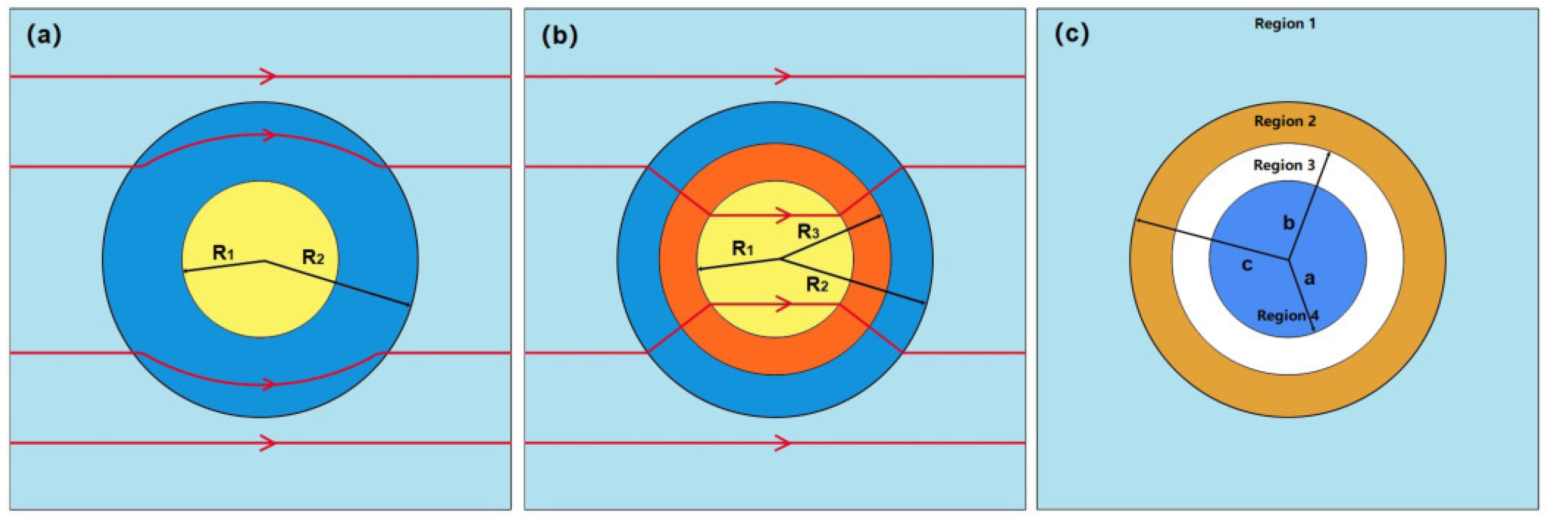
The traditional cloak should ensure that the heat does not flow into the cloak. Thus, the center of the device holds a zero temperature gradient without disturbing the external temperature distribution. As shown in Figure 1a, the region I is the cloaking area where the heat flow will not be allowed to enter. Referring to the transformation theory, the circle of radius should be mapped to a ring whose interior radius is and the exterior radius is . on the other hand, the traditional concentrator would make more heat flux penetrating into the central area and increase the local temperature gradient. As illustrated in Figure 1b, the coordinate transformation to achieve concentrating is to compress the ring with interior radius and exterior radius into a ring with interior radius and exterior radius . Following the above discussion, we can give the coordinate transformation relationship of cloak in polar coordinates :
as well as the concentrator
One can easily prove that the Laplace equation will keep form invariance under the coordinate transformation while the conductivity changes accordingly. Therefore, the variation of the coordinates is equivalence to a mapping transformation applied to the conductivity tensor, i.e., the new conductivity in the transformed space in both the thermal and the DC electrical field follows the rule
where J, , are the Jacobian matrix, its transpose and determinant respectively. It should be noted that , so J is a mathematical tool to describe the corresponding coordinate transformation.
Next, we want to endow the device the function to switch from a cloak to a concentrator or vice versa. After checking the coordinate transformation relationship in Equations (5) and (6), we find it is practicable by just replacing the in Equation (5) as a variable and set a specific function that makes at the cloak state while in concentrator case. Obviously, if is dependent on the ambient temperature T or the voltage V, as the external field changes the device would automatically switch from one function to another. Due to the balance of the resistor heating and the dissipative cooling in a steady state, through some engineering design, one can always calibrate the voltage associated with a certain value of the temperature. Hence, to realize the “intelligent” switching effect in both thermal and DC electrical conduction, it is convenient for us to regard the as a function of T.
Now we are in a position to prove that the temperature dependent coordinate transformation can not disturb the conduction equation’s form. In 2015, Li et al. [20] has demonstrated that for a material with temperature dependent conductivity, the conduction equation is still form invariance under the coordinated transformation and the desired parameter holds the same form as Equation (7). Furthermore, the validity of the transformation theory on the temperature-dependent conductivity is equivalent to a temperature-dependent transformation applied to the medium with a temperature independent conductivity, i.e.,
where represents the temperature dependent coordinate transformation.
Therefore, we can extend their conclusions to our derivation in consideration of the Wiedemann-Franz law. The form of can be set as:
here is the scaling factor which determines the sensitivity of the device’s structure to T. As shown in the above equation, we provide two forms of , since the device should be able to automatically switch between cloak state and concentrator state as the ambient temperature changes. Owing to the , we rewrite the Equations (5) and (6) in one formula:
Taking the above coordinate transformation into the Equation (7), the thermal/electrical conductivity of the bi-functional device can be derived as
where and are the radial and azimuthal components of and the is the conductivity of the background medium. For the equations above, the function of device will be decided by the temperature and the form of . For Form I, when temperature is lower than the critical temperature , the device will show the property of concentrator which will let more heat flux or current flow into the central zone. On the other hand, when the environmental temperature increases to a higher temperature then , the device will switch to cloak mode which will prohibit heat flux or current from entering the cloaking region. Oppositely, for Form II, the device will function as a cloak at low environmental temperature, while at the high temperature it will turn to a concentrator.
However, the conductivity obtained from the transformation theory is extremely anisotropic and inhomogeneous, which is very complicated to be realized in practice. In order to reduce the difficulty in fabricating such device, referring to the design of the bilayer cloak [13], we propose a simplify bi-functional model by utilizing normal materials whose conductivities are homogeneous and isotropic. As shown in Figure 1c, the conductivities of the host (region 1), outer layer (region 2), inner layer (region 3), and cloaking area (region 4) are indicated as , , , and respectively. Considering a steady state two-dimensional conduction system without source in a polar system , if all the mediums involved are isotropic and homogenous, the Laplace equation in Equation (3) can be expressed as
Taking account of the model’s upper and lower parts are symmetrical, the general solutions of in different regions are derived as
where n is a integer, and , are parameters determined by the boundary conditions. Assume the ambient temperature gradient is . The distribution of far from the heat source should tend to uniform, i.e., . Namely, only the first order parameters in Equation (12) are retained. Hence, we obtain and . In addition, as r tends to zero, the is a finite value leading to the . The object inside the cloak region should not disturb the outside field distribution, so . Finally, according to the continuity of the heat flux or the electrical currency, the desired conductivities for a bilayer cloak can be obtained
Here, C is an arbitrary value.
Next, we will derive the conductivities of region 1–4 for a bilayer concentrator. Similar to the results given in the Equation (10) by adopting the transformation theory, to assemble two functions in one device, we need to cost the least effort to accomplish the functions switching. Thus, the cloak and the concentrator should share as more parameters as possible. By solving the general solutions of Equation (12), the optimum solution of the concentrator’s conductivities are given below:
where D is an undetermined coefficient just as C in Equation (13). Apparently, to build the device, we can select a material with the conductivity of in the region 4 to ensure the concentrating effect without affecting the invisible characteristic and try to find a method to make the switch between D and a very small value as the temperature varies. In summary, the parameters of the bi-functional multi-physics metamaterial are listed below
3. Design of the Meta-Device
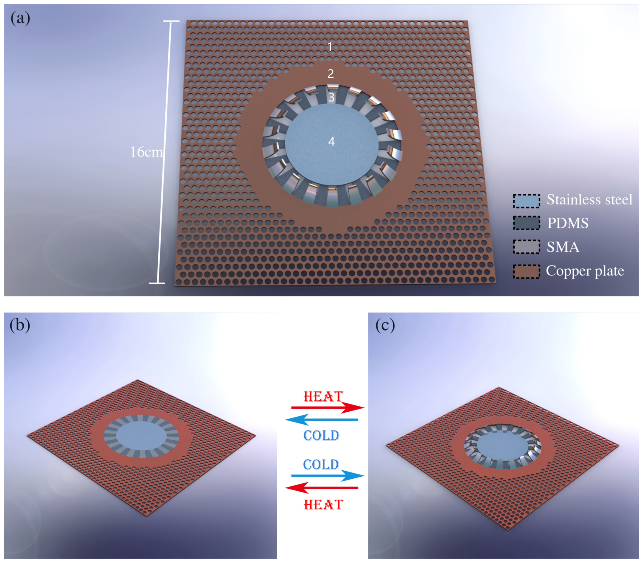
A schematic of our design is illustrated in the Figure 2a and all the parameters of this design will be used in both simulations and experimental demonstrations. According to the previous discussion, once we have identified the materials of each regions, the relationship between the dimensions of each regions will be determined. Hence the quasi two dimensional device is made of a copper (, ) plate with a thickness of cm. The copper has a very high thermal conductivity among the common materials, and the high conductivity will benefit the dominance of the thermal conduction rather than the convective or radiation. The radii of the regions 4, 3, 2 are cm, cm and cm. To satisfy the demands of the appropriate geometry dependent relationships between conductivities of different regions, for convenient, we set the region 2 as the pure copper medium. It is hard to find a metal with the matched conductivity as the host medium in region 1 since the thermal conductivity of the metal has a gap approximately between and . Fortunately, the effective medium theory [6,17,33] can provide a way to meet the conductivity requirements by mixing multiple materials with appropriate proportions. As depicted in the graph, one can drill small holes evenly on the copper plate and fill the holes with the polydimethylsiloxane (PDMS) (, ). The effective conductivity of the mixture will follow the rule: , where P is the volume fraction of the copper. Thus, by adjusting the volume fraction P, one can tune the conductivity of the region 1 within a large range. In our model, . Moreover, using a whole piece of copper to form both the region 1 and region 2 can reduce the thermal impedance caused by contact thermal resistance between different materials.
As aforementioned, instead of achieving the temperature dependent conductivity, we can design a temperature dependent structure [20,21,34]. Therefore, we resort to the shape memory alloys (SMA) which are kinds of shape memory materials which are able to return to their original shape from visible deformation state [35]. This shape-memory property correlates to a solid-solid phase transition named as the martensitic transformation [36]. This transformation is due to the cubic lattice’s transferring to another lattice with lower symmetry, such as a tetragonal structure. During the transition, the lattice structure of the SMA will transform among three different phases of austenite, twinned martensite or detwinned martensite depending on the history of the thermal-stress change. The details of the phase transitions have been discussed by Sun. et al. in 2012 [37]. In this work, the SMA are driven by the temperature and can be utilized to construct a moveable structure in region 3 which can provide two states of effective conductivities. In our design, the slices of SMA can be welded to the other metals, and as their welding spots’ temperatures are enhanced the slices either bend or become straight. Moreover, since the thermal conductivity and electrical conductivity of SMA are small, to ensure the conduction effect, a copper slice with the same dimensions is stuck to the SMA slice to construct a parallel conduction structure. For this two metals’ coupling bi-slices, the conductivity is at the same order as the copper, and the SMA only provides the driven force to make the structure deform. To build the region 3, as shown in Figure 2a, two types of materials in the shapes of sheets with the same length of are alternately arrayed along the tangential direction to form a ring. One type of sheet is made of the insulator PDMS and the other one is the bi-slices of SMA and copper. According to the effective medium theory [6,17,33], the thermal conductivity of this structure should be . For the electric conductivity, since the PDMS is an insulator, the above effective approximation is invalid, we adopt the same Lorentz parameter of copper to estimate . Thus, as shown in the Figure 2b,c when we impose a temperature gradient to the sample, the heated 18 SMA sawtooth in region 3 will tilt up leading to an alternation from a connection state to a disconnection state which makes the device switch from a concentrator to a cloak or vice versa. For the DC electrical conduction, one can set small resistor wires around those SMA slices. As the circuit is turned on, through careful design, the resistor wires will be heated and force the sawtooth to deform. It is worth noting although this function switching effect is temperature dependent, it still can seem as an apparent "intelligent" active associated with the change of the electric field. After figuring out the conductivity of region 3, the can be calculated. The result is very close to the stainless steel, whose thermal/electric conductivity is /. Hence, a circular stainless steel film is placed in region 4.
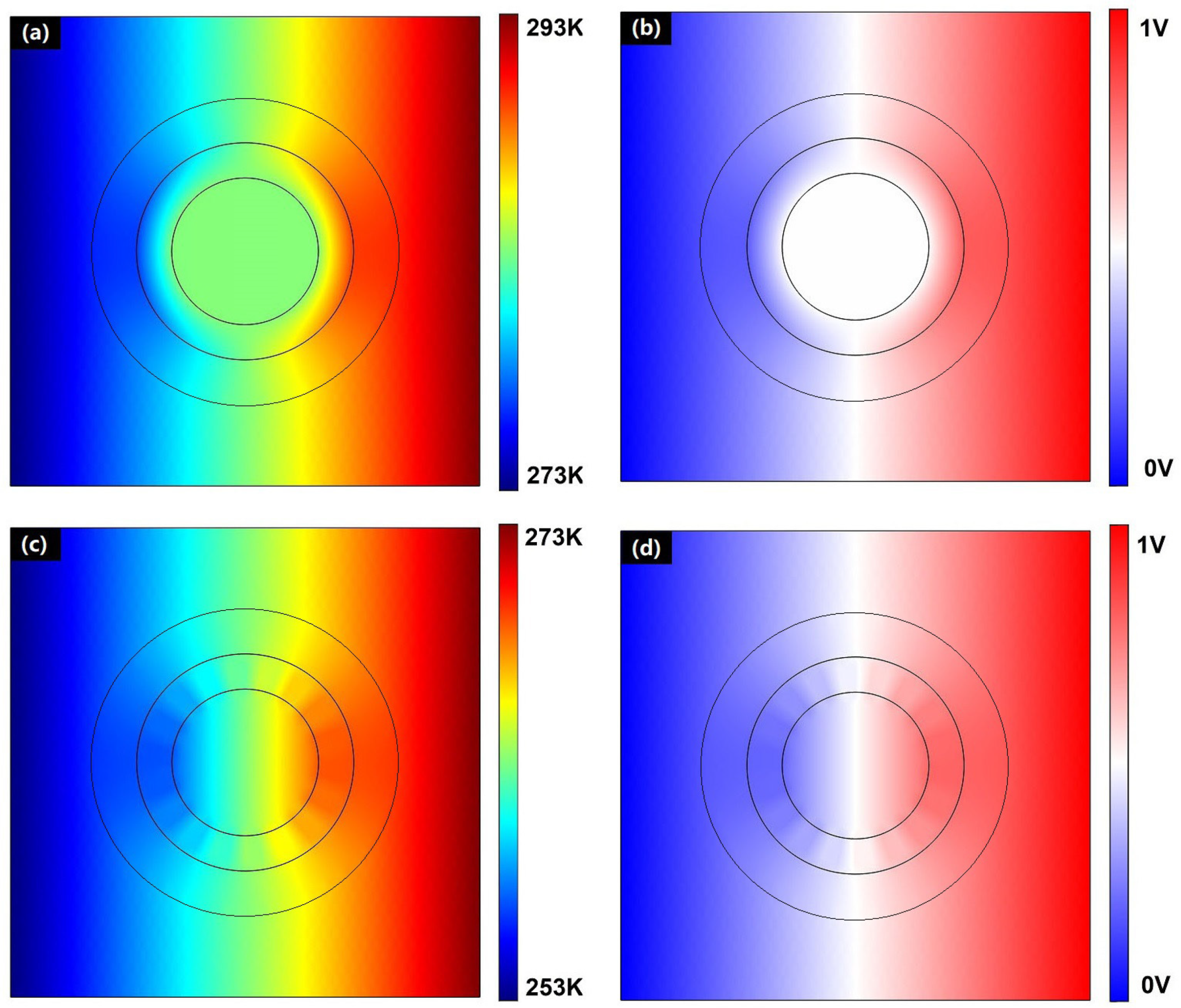
In order to further prove the feasibility of our scheme, simulations are performed by applying for the commercial software COMSOL Multiphysics. By using the relevant data of the actual materials in the software and setting the critical temperature of SMA transition at K, the simulation can predict the experimental results, which are presented in the Figure 3. For the cloaking state, the distributions of the temperature and the voltage in the thermal and DC electrical conduction case are demonstrated in the Figure 3a,b respectively. On the other hand, Figure 3c,d give the field distributions when the device act as a concentrator. The results show the multi-physics bi-functional device works perfectly. As the device is the cloak, the central region holds no potential gradient since no heat flux or electrical currency flows in, while as the concentrator, the gradient inside the region 4 is enhanced. Moreover, in both cases, the external potential distribution is uniform. It should be noted there exist some slight distortions of the temperature/voltage distribution in the region 2 and 3 due to the shape of the SMA slices. Since we cannot give the exact voltage value that triggers the bending of the SMA due to the lack of heat dissipation information in the simulation, the difference of the electric potential for both cloak and concentrator cases are set to be 1 V.
According to the simulation results we can fabricate the samples of such intelligent devices practically. In Figure 4a,b, we show two forms of such devices, which possess two different functions associated with two different structures that can be tuned by the ambient temperature. The device on the right functions as a cloak when all the SMA sawteeth are flattened at a low temperature of 5 , and it will switch to a concentrator when the SMA slices tilt up as the environment is heated to reach the critical temperature at 25 . The left one is a concentrator at the same low temperature and can switch to a cloak at 25 . Figure 5c,d are the thermal images of one device captured by the infrared thermal imager FILR E60, and (c) is the temperature field distribution for the cloak while (d) is the counterpart of the concentrator. The experimental results for the thermal conduction are in good agreements with the simulation results. It should be noted that the effects of thermal convection and thermal radiation are sub-dominant and can be neglected in the material with such high conductivity. In addition, for such a small range of temperature variation (5 to 25 ), the thermal conductivities for metals are proportional to the electrical conductivities and will not change with the temperature.
For the electrical field, if one tries to perform the experiment, the first confronted problem is how to obtain a uniform electric potential distribution, since the imposed voltage on the sample always existing as the form of the point source leading to the non-uniform voltage distribution, especially when the high thermal/electric conductivity materials are selected to constitute the sample. So it is hard to give a good electrical field image as the thermal conduction case. However due to the same form of the domain equation, theoretically, the performances of our bi-functional device in DC electric filed can be guaranteed just as the simulation results illustrated in the Figure 3.
4. Discussion and Conclusions
One may find the values of the of different metals are not strictly equivalent as implicated by Wiedemann-Franz law, and due to the mismatch of the thermal and the electrical conductivities one may also worry about that the device consisting of these materials cannot perform perfectly in both thermal and electric fields. This fact has been mentioned by Yang et al. [28] before. In that paper, they point out a method to solve the problem by mixing another material with a higher value of on the interface. In our design, the PMDS works as the high ratio material. In addition, it is unnecessary to achieve a perfect cloak, in which the constant . If is small enough, there are no detectable distortions of the field outside the device. Therefore, the tolerance of the conductivities’ mismatching is actually much higher. As observed from the simulation results, this mismatch has little effect on our design.
What is more, the ratio of will also be affected by the temperature difference. To illustrate this effect, we give the contour distributions at different temperature differences. In Figure 5a,b, the red lines denote the isothermal lines in the same cloak device at different temperature differences: (a) is 50 K; (b) is 200 K. As the references, the blue lines indicate the electric equipotential lines and the potential difference between the two edges of the device is set as 1 V in both (a) and (b). As the temperature difference increase to 200 K, the obvious divergences between the two contours start to appear. Similarly, comparing to the differences between the red lines and blue ones in Figure 5c,d, the same results can also be observed in the concentrator state. Intriguingly, the divergences cannot be detected in regions 1 and 2 for the cloaking case. Taking account of no flux can enter into the region 4 and region 1, 2 are made of a whole copper plate, it implies that this distortion is induced by the coupling of different metals. However, according to the simulation results, the affections of the temperature do not have a significant impact on the functionality of the device.
To sum up, in this article we have extended the bi-functional devices from the thermal field to the multiple physics field. We have proposed the desired conductivities to achieve a type of metamaterial that permits a device to sense the variation of the ambient temperature or electric potential field and altering between a cloak and a concentrator. Practical design to realize this function switching effect in both thermal and DC electrical conduction by utilizing the shape memory alloys are also given. In addition, the performance of our design can be confirmed by the finite element simulations. If one can impose a uniform surface potential source on the device’s boundary and the SMA slices’ straight state can be improved to provide robust connections between different regions, the experiment can be further performed.
Author Contributions
Conceptualization, X.S.; methodology, C.J. and X.S.; software, C.J. and X.S.; validation, C.J., C.F. and X.S.; formal analysis, C.J., C.F. and X.S.; investigation, C.J. and X.S.; resources, C.J. and X.S.; data curation, C.J. and X.S.; writing–original draft preparation, C.J.; writing–review and editing, X.S.; visualization, X.S.; supervision, X.S.; project administration, X.S.; funding acquisition, C.J. and X.S.
Funding
This research was funded by National Natural Science Foundation of China grant number 11725521.
Acknowledgments
We acknowledge Li Ying for the discussion.
Conflicts of Interest
All the authors declare no conflicts of interest. The funders had no role in the design of the study; in the collection, analyses, or interpretation of data; in the writing of the manuscript, or in the decision to publish the results.
References
- Leonhardt, U. Optical conformal mapping. Science 2006, 312, 1777. [Google Scholar] [CrossRef] [PubMed]
- Pendry, J.B.; Schurig, D.; Smith, D.R. Controlling electromagnetic fields. Science 2006, 312, 1780. [Google Scholar] [CrossRef] [PubMed]
- Pramanick, A.; Wang, X.L.; Stoica, A.D.; Yu, C.; Ren, Y.; Tang, S.; Gai, Z. Kinetics of magnetoelastic twin-boundary motion in ferromagnetic shape-memory alloys. Phys. Rev. Lett. 2014, 112, 217205. [Google Scholar] [CrossRef]
- Savo, S.; Zhou, Y.; Castaldi, G.; Moccia, M.; Galdi, V.; Ramanathan, S.; Sato, Y. Reconfigurable anisotropy and functional transformations with -based metamaterial electric circuits. Phys. Rev. B 2015, 91, 134105. [Google Scholar] [CrossRef]
- Schittny, R.; Kadic, M.; Buckmann, T.; Wegener, M. Invisibility cloaking in a diffusive light scattering medium. Science 2014, 345, 427. [Google Scholar] [CrossRef]
- Gao, Y.; Huang, J.P.; Liu, Y.M.; Gao, L.; Yu, K.W.; Zhang, X. Optical negative refraction in ferrofluids with magnetocontrollability. Phys. Rev. Lett. 2010, 104, 034501. [Google Scholar] [CrossRef] [PubMed]
- Zigoneanu, L.; Popa, B.-I.; Cummer, S.A. Three-dimensional broadband omnidirectional acoustic ground cloak. Nat. Mater. 2014, 13, 352. [Google Scholar] [CrossRef]
- Fan, C.Z.; Gao, Y.; Huang, J.P. Shaped graded materials with an apparent negative thermal conductivity. Appl. Phys. Lett. 2008, 92, 251907. [Google Scholar] [CrossRef]
- Guenneau, S.; Amra, C.; Veynante, D. Transformation thermodynamics: Cloaking and concentrating heat flux. Opt. Express 2012, 20, 8207. [Google Scholar] [CrossRef]
- Narayana, S.; Sato, Y. Heat flux manipulation with engineered thermal materials. Phys. Rev. Lett. 2012, 108, 214303. [Google Scholar] [CrossRef]
- Schittny, R.; Kadic, M.; Guenneau, S.; Wegener, M. Experiments on transformation thermodynamics: Molding the flow of heat. Phys. Rev. Lett. 2013, 110, 195901. [Google Scholar] [CrossRef] [PubMed]
- Xu, H.; Shi, X.; Gao, F.; Sun, H.; Zhang, B. Ultrathin three-dimensional thermal cloak. Phys. Rev. Lett. 2014, 112, 054301. [Google Scholar] [CrossRef] [PubMed]
- Han, T.C.; Bai, X.; Gao, D.L.; Thong, J.T.L.; Li, B.W.; Qiu, C.W. Experimental demonstration of a bilayer thermal cloak. Phys. Rev. Lett. 2014, 112, 054302. [Google Scholar] [CrossRef] [PubMed]
- Nguyen, D.M.; Xu, H.; Zhang, Y.; Zhang, B. Active thermal cloak. Appl. Phys. Lett. 2015, 107, 121901. [Google Scholar] [CrossRef]
- Li, Y.; Bai, X.; Yang, T.; Luo, H.; Qiu, C. Structured thermal surface for radiative camouflage. Nat. Commun. 2018, 9, 273. [Google Scholar] [CrossRef] [PubMed]
- Li, Y.; Zhu, K.J.; Peng, Y.G.; Li, W.; Yang, T.Z.; Xu, H.X.; Chen, H.; Zhu, X.F.; Fan, S.H.; Qiu, C.W. Thermal meta-device in analogue of zero-index photonics. Nat. Mater. 2019, 18, 4854. [Google Scholar] [CrossRef] [PubMed]
- Li, J.Y.; Gao, Y.; Huang, J.P. A bifunctional cloak using transformation media. J. Appl. Phys. 2010, 108, 074504. [Google Scholar] [CrossRef]
- Shen, X.Y.; Huang, J.P. Thermally hiding an object inside a cloak with feeling. Int. J. Heat Mass Transf. 2014, 78, 1. [Google Scholar] [CrossRef]
- Han, T.C.; Bai, X.; Thong, J.T.L.; Li, B.; Qiu, C.W. Full control and manipulation of heat signatures: Cloaking, camouflage and thermal metamaterials. Adv. Mater. 2014, 26, 1731. [Google Scholar] [CrossRef]
- Li, Y.; Shen, X.Y.; Wu, Z.H.; Huang, J.Y.; Chen, Y.X.; Ni, Y.S.; Huang, J.P. Temperature-dependent transformation thermotics: From switchable thermal cloaks to macroscopic thermal diodes. Phys. Rev. Lett. 2015, 115, 195503. [Google Scholar] [CrossRef]
- Shen, X.; Li, Y.; Jiang, C.; Ni, Y.; Huang, J. Thermal cloak-concentrator. Appl. Phys. Lett. 2016, 109, 031907. [Google Scholar] [CrossRef] [Green Version]
- Han, T.C.; Zhao, J.; Yuan, T.; Lei, D.Y.; Li, B.W.; Qiu, C.W. Theoretical realization of an ultra-efficient thermal-energy harvesting cell made of natural materials. Energy Environ. Sci. 2013, 6, 3537. [Google Scholar] [CrossRef]
- Han, T.C.; Bai, X.; Thong, J.T.L.; Li, B.W.; Qiu, C.W. Manipulating DC currents with bilayer bulk natural materials. Adv. Mater. 2014, 26, 3478. [Google Scholar] [CrossRef] [PubMed]
- Han, T.C.; Bai, X.; Liu, D.; Gao, D.L.; Li, B.W.; Thong, J.T.L.; Qiu, C.W. Manipulating Steady Heat Conduction by Sensu-shaped Thermal Metamaterials. Sci. Rep. 2015, 5, 10242. [Google Scholar] [CrossRef] [PubMed]
- Bell, L.E. Cooling, heating, generating power, and recovering waste heat with thermoelectric systems. Science 2008, 321, 1457. [Google Scholar] [CrossRef] [PubMed]
- Moccia, M.; Castaldi, G.; Savo, S.; Sato, Y.; Galdi, V. Independent manipulation of heat and electrical current via bifunctional metamaterials. Phys. Rev. X 2014, 5, 021025. [Google Scholar] [CrossRef]
- Ma, Y.; Liu, Y.; Raza, M.; Wang, Y.; He, S. Experimental demonstration of a multiphysics cloak: Manipulating heat flux and electric current simultaneously. Phys. Rev. Lett. 2014, 113, 205501. [Google Scholar] [CrossRef] [PubMed]
- Yang, T.Z.; Bai, X.; Gao, D.L.; Wu, L.Z.; Li, B.W.; Thong, J.T.L.; Qiu, C.W. Invisible sensors: Simultaneous sensing and camouflaging in multiphysical fields. Adv. Mater. 2015, 27, 7752. [Google Scholar] [CrossRef]
- Wen, Y.H.; Peng, H.B.; Raabe, D.; Gutierrez-Urrutia, I.; Chen, J.; Du, Y.Y. Large recovery strain in Fe-Mn-Si-based shape memory steels obtained by engineering annealing twin boundaries. Nat. Commun. 2014, 5, 4964. [Google Scholar] [CrossRef] [Green Version]
- Tian, X.; Zhang, K.; Tan, C.; Guo, E. Influence of Doping Tb on the Mechanical Properties and Martensitic Transformation of Ni-Mn-Sn Magnetic Shape Memory Alloys. Crystals 2018, 8, 247. [Google Scholar] [CrossRef]
- Li, W.; Zhao, C. Microstructure and Phase Transformation Analysis of Ni50-xTi50Lax Shape Memory Alloys. Crystals 2018, 8, 345. [Google Scholar] [CrossRef]
- Huang, W. On the selection of shape memory alloys for actuators. Mater. Des. 2002, 23, 1119. [Google Scholar] [CrossRef]
- Huang, J.P.; Yu, K.W. Enhanced nonlinear optical responses of materials: Composite effects. Phys. Rep. 2006, 431, 87. [Google Scholar] [CrossRef]
- Shen, X.Y.; Li, Y.; Jiang, C.R.; Huang, J.P. Temperature trapping: Energy-free maintenance of constant temperatures as ambient temperature gradients change. Phys. Rev. Lett. 2016, 117, 055501. [Google Scholar] [CrossRef]
- Huang, W.M.; Ding, Z.; Wang, C.C.; Wei, J.; Zhao, Y.; Purnawali, H. Shape memory materials. Mater. Today 2010, 13, 5461. [Google Scholar] [CrossRef]
- Omori, T.; Kainuma, R. Materials science: Alloys with long memories. Nature 2013, 502, 4244. [Google Scholar] [CrossRef]
- Sun, L.; Huang, W.M.; Ding, Z.; Zhao, B.Y.; Wang, C.C.; Purnawali, H.; Tang, B.C. Stimulus-responsive shape memory materials: A review. Mater Des. 2012, 33, 577640. [Google Scholar] [CrossRef]
Figure 1.
(a) Schematic graph shows the cloak device and the trace of the heat flux/electric currency affected by it. (b) Schematic graph shows the concentrator device and the trace of the heat flux/electric currency. (c) The design of a bilayer cloak.
Figure 1.
(a) Schematic graph shows the cloak device and the trace of the heat flux/electric currency affected by it. (b) Schematic graph shows the concentrator device and the trace of the heat flux/electric currency. (c) The design of a bilayer cloak.

Figure 2.
(a) Blueprint of our experimental sample. The holes on the sample filled with PDMS can be achieved by chemically etching. (b) The straightened SMA slices lead to cloak state of the bi-functional multi-physics device. (c) The tilted up SMA slices lead to the concentrator state of the bi-functional multi-physics device. The arrows in different colors implies the temperature variation can trigger the switching effect.

Figure 3.
Finite-element simulation results of the temperature/voltage distributions in the structure displayed in Figure 2. (a) the temperature distribution of the cloak state; (b) the voltage distribution of the cloak state; (c) the temperature distribution of the concentrator state; (d) the voltage distribution of the concentrator state.

Figure 4.
(a,b) are the photograph of the fabricated device. The device are constructed by using two different types of SMAs: one is flattened at 5 and tilts up at 25 ; the other one is flattened at 25 and tilts up at 5 . (c) shows the temperature image of the cloak state captured by infrared thermal imager and (d) gives the temperature distribution of the concentrator state.
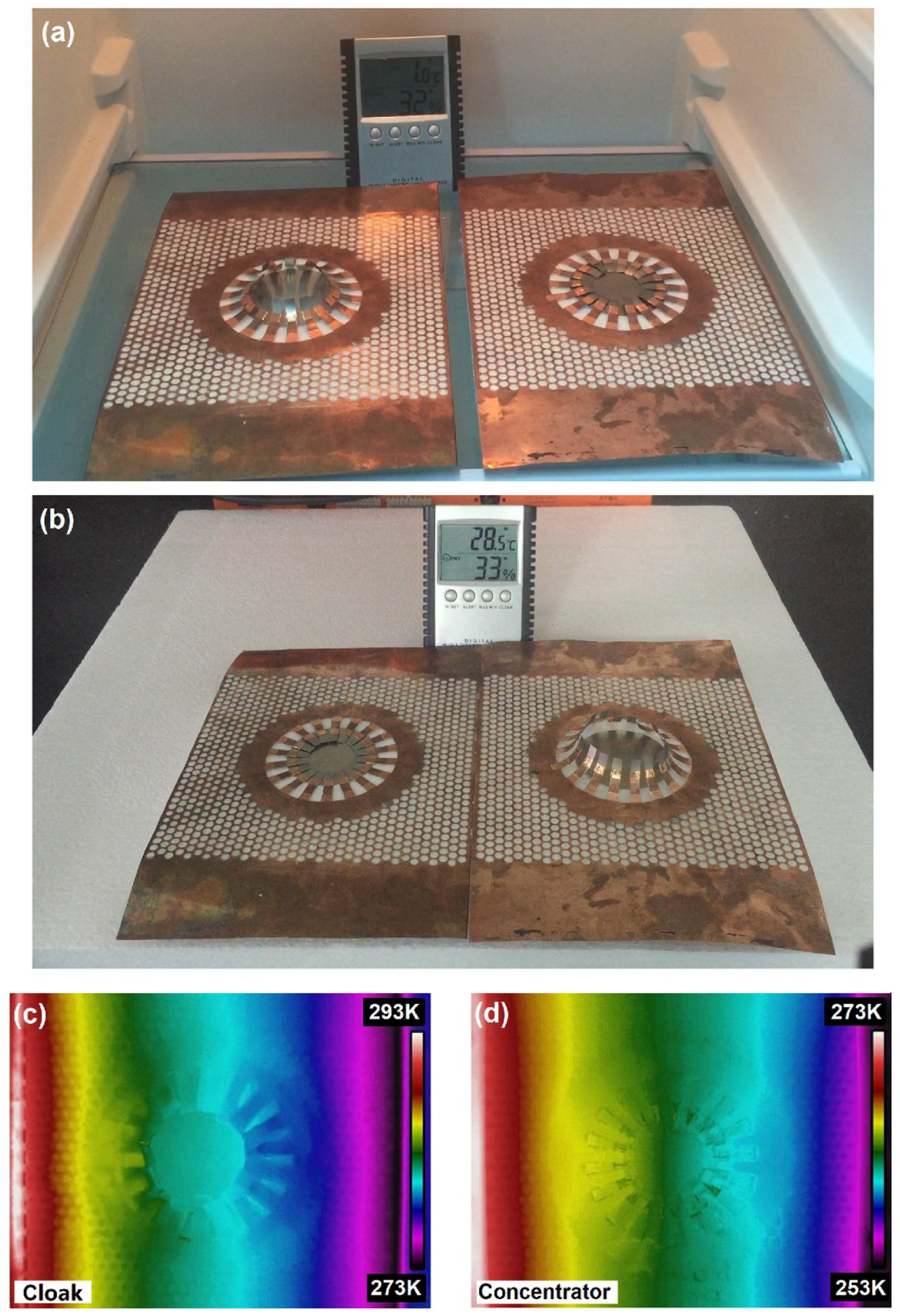
Figure 5.
Finite-element simulation results: Equipotential lines of both voltage and temperature. The blue lines denote the electrical equipotential lines and the red lines denote the isothermal lines. The electrical potential difference between the two boundaries of the device is set as 1 V, so the blue lines will not distort as the temperature is enhanced, and can be seem as invariant references. (a) the cloak state at the temperature 50 K; (b) the cloak state at the temperature 200 K; (c) the concentrator state at the temperature 50 K; (d) the concentrator state at the temperature 200 K.

© 2019 by the authors. Licensee MDPI, Basel, Switzerland. This article is an open access article distributed under the terms and conditions of the Creative Commons Attribution (CC BY) license (http://creativecommons.org/licenses/by/4.0/).
Share and Cite
MDPI and ACS Style
Jiang, C.; Fang, C.; Shen, X. Multi-Physics Bi-Functional Intelligent Meta-Device Based on the Shape Memory Alloys. Crystals 2019, 9, 438. https://doi.org/10.3390/cryst9090438
AMA Style
Jiang C, Fang C, Shen X. Multi-Physics Bi-Functional Intelligent Meta-Device Based on the Shape Memory Alloys. Crystals. 2019; 9(9):438. https://doi.org/10.3390/cryst9090438
Chicago/Turabian StyleJiang, Chaoran, Chenchao Fang, and Xiangying Shen. 2019. "Multi-Physics Bi-Functional Intelligent Meta-Device Based on the Shape Memory Alloys" Crystals 9, no. 9: 438. https://doi.org/10.3390/cryst9090438
Note that from the first issue of 2016, this journal uses article numbers instead of page numbers. See further details here.