Article

Induced Nucleation of Biomimetic Nanoapatites on Exfoliated Graphene Biomolecule Flakes by Vapor Diffusion in Microdroplets

by
Jaime Gómez-Morales
1,*,
Luis Antonio González-Ramírez
1,
Cristóbal Verdugo-Escamilla
1,
Raquel Fernández Penas
1,
Francesca Oltolina
2,
Maria Prat
2 and
Giuseppe Falini
3,*
1
Laboratorio de Estudios Cristalográficos, IACT, CSIC-UGR. Avda. Las Palmeras 4, 18100 Armilla, Granada, Spain
2
Dipartimento di Scienze della Salute, Università del Piemonte Orientale, Via Solaroli, 17, 28100 Novara, Italy
3
Dipartimento di Chimica “Giacomo Ciamician”, Alma Mater Studiorum Università di Bologna, via Selmi 2, 40126 Bologna, Italy
*
Authors to whom correspondence should be addressed.
Crystals 2019, 9(7), 341; https://doi.org/10.3390/cryst9070341
Submission received: 4 June 2019 / Revised: 24 June 2019 / Accepted: 1 July 2019 / Published: 3 July 2019
(This article belongs to the Special Issue Biological Crystallization)

Abstract

:
The nucleation of apatite nanoparticles on exfoliated graphene nanoflakes has been successfully carried out by the sitting drop vapor diffusion method, with the aim of producing cytocompatible hybrid nanocomposites of both components. The graphene flakes were prepared by the sonication-assisted, liquid-phase exfoliation technique, using the following biomolecules as dispersing surfactants: lysozyme, L-tryptophan, N-acetyl-D-glucosamine, and chitosan. Results from mineralogical, spectroscopic, and microscopic characterization (X-ray diffraction (XRD), Fourier transform infrared spectroscopy (FTIR), Raman, Variable pressure scanning electron microscopy (VPSEM), and transmission electron microscopy (TEM)) indicate that flakes were stacked in multilayers (>5 layers) and most likely intercalated and functionalized with the biomolecules, while the apatite nanoparticles were found forming a coating on the graphene surfaces. It is worthwhile to mention that when using chitosan-exfoliated graphene, the composites were more homogeneous than when using the other biomolecule graphene flakes, suggesting that this polysaccharide, extremely rich in –OH groups, must be arranged on the graphene surface with the –OH groups pointing toward the solution, forming a more regular pattern for apatite nucleation. The findings by XRD and morphological analysis point to the role of “functionalized graphene” as a template, which induces heterogeneous nucleation and favors the growth of apatite on the flakes’ surfaces. The cytocompatibility tests of the resulting composites, evaluated by the 3-(4,5-Dimethylthiazol-2-yl)-2,5-diphenyltetrazolium bromide (MTT) colorimetric assay in a dose–dependent manner on GTL-16 cells, a human gastric carcinoma cell line, and on m17.ASC cells, a murine mesenchymal stem cell line with osteogenic potential, reveal that in all cases, full cytocompatibility was found.

Graphical Abstract

1. Introduction

In the last decade there has been increasing interest in the preparation of graphene/apatite hybrid nanocomposites and their derivatives, combining the bioactive properties of the nanocrystalline apatite with the mechanical strength of graphene for uses in load-bearing applications in bone tissue engineering [1]. Nanocrystalline apatites are the main inorganic components of bone and dentine. Compared to stoichiometric hydroxyapatite Ca5(OH)(PO4)3, which is the most stable calcium phosphate at ambient temperature, nanocrystalline apatites are non-stoichiometric calcium- and OH- deficient, plate-shaped, and present a series of substituted ions within their crystal structure, including carbonate (4%–6%), Na (0.9%), Mg (0.5%), and other minor elements [2]. Biomimetic nanocrystalline apatites exhibit excellent biological properties, such as biocompatibility, osteoconductivity, and osteoinductivity [2]. In clinical practice, for applications in dental and orthopedic surgery, they are usually employed as a bioactive coating on a metallic support, combining the biological properties of the apatite with the mechanical strength of the support, thus promoting a fast fixation within the surrounding bony tissue. To this end, different calcium phosphate (CaP) coating methods, employing biocompatible titanium and titanium alloy supports, were developed in the past [3,4,5,6,7]. When the apatite is used as a synthetic bone graft, however, because of its intrinsic brittleness and low fracture toughness, the use of a reinforcing material to form a composite scaffold with better mechanical properties is necessary. The presence of this second component in the composite is aimed at improving the long-term functionality of the graft after clinical surgery, under load-bearing conditions. Among the used materials, it is worth mentioning different polymers, such as poly(L-lactic acid) (PLA) [8], poly(ε-caprolactone) (PCL) [9], ceramics [10], carbon nanotubes [11], and more recently, graphene or graphene derivatives [12]. Few of the materials tested displayed favorable biocompatibility with sufficient mechanical properties [12]. For example, PCL/apatite composites displayed excellent bioactivity and improved mechanical properties by increasing the apatite content [9]. However, carbon nanotubes are good reinforcing materials, but still present certain toxicity [12]. The use of graphene has been proposed as an alternative component to overcome these troubles.
Graphene is the model of a two-dimensional (2D) nanomaterial, which consists of a single sheet of carbon atoms covalently bonded in a hexagonal network, therefore presenting an extremely large specific surface area (theoretically 2700 m2/g). The importance of this material has been recognized since it was isolated in 2004 [13]. This carbon allotrope exhibits exceptional properties, such as high mechanical strength, optimal thermal conductivity, and excellent electrical conductivity [14,15]. Graphene has shown promise as 2D scaffold for controlled growth and the osteogenic differentiation of human mesenchymal stem cells [16], or as a substrate to promote the adherence of human osteoblasts and mesenchymal stromal cells [17]. In addition, graphene and its derivatives, such as graphene oxide and reduced graphene oxide, have shown a good biocompatibility, which is a requirement for their biomedical applications [18].
Different preparation methods of hybrid graphene/apatite nanocomposites and their derivative nanomaterials have been proposed over the last 10 years of research, including in situ synthesis, biomimetic mineralization, hydrothermal synthesis, and chemical vapor deposition [1]. During this period, we reported for the first time a new methodology to precipitate biomimetic apatite nanoparticles [19] and other calcium phosphates [20] in microliter droplets by the vapor diffusion sitting drop (VDSD) micromethod. Vapor diffusion in milliliter scale vessels was employed contemporaneously by other research teams to obtain biomimetic calcium phosphates [21]. The VDSD method was previously employed for in vitro studies of CaCO3 biocrystallization, in both the absence and presence of proteins [22,23] and biological fluids [24]. The vapor diffusion technique was also used to precipitate CaCO3 calcite single crystals induced by the graphene biomolecule adduct [25]. The two main features of the VDSD technique are the control of the gas diffusion rate of NH3 and CO2 by simply changing the concentration of NH4HCO3 in a gas generation chamber, which acts as a reagent reservoir, and the confinement of the nucleation in isolated microdroplets located in a precipitation chamber. These microdroplets closely mimic the in vivo microenvironments where biominerals form. The disadvantage of the technique is the very small amount of precipitate for its subsequent characterization. Our team has recently used this method to induce the heterogeneous nucleation and growth of CaP films on mica sheets [26]. In the present work, we propose to extend this precipitation micromethod to induce the heterogeneous nucleation of nanocrystalline apatites on exfoliated graphene flakes, as the model of a bidimensional material scaffold. The final goal is to assess the usefulness of this methodology to obtain cytocompatible hybrid nanocomposites consisting of graphene and biomimetic apatite.

2. Materials and Methods

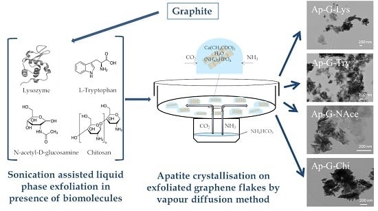
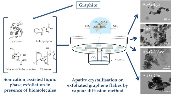
2.1. Exfoliated Graphene Flakes

Graphene flakes were prepared by the sonication-assisted liquid-phase exfoliation (LPE) technique [27]. Basically, the graphene flakes were prepared by exfoliating graphite suspensions in an ultrasonic bath in the presence of the following biomolecules, acting as dispersing surfactants (Figure 1, left): lysozyme (Lys), L-tryptophan (Try), N-acetyl-D-glucosamine (NAce), and chitosan (Chi) (high purity > 99%, from Sigma-Aldrich S.r.l., Milan, Italy). Typically, 20 mL glass vials containing 10 mL of water suspensions, prepared by mixing 100 mg of graphite powder (Sigma-Aldrich, purity 99.99%) and either 1.44 mg Lys, 2 mg Try, 2.2 mg NAce, or 40 mg Chi in ultrapure water, were sonicated in an ice bath for 5 hours. The suspensions were centrifuged at 3500 rpm for 5 min, and the supernatant was again sonicated for 1 hour and centrifuged for 5 min. After centrifugation, the supernatant was carefully removed with a micropipette. The as-prepared graphene dispersions were stored at 4 °C prior to the mineralization experiments. The dispersions were stable for more than one week.

2.2. Precipitation Method

Precipitation experiments were carried by the VDSD method on several “crystallization mushrooms” (Triana Sci. & Tech, S.L., Armilla, Spain) at 20 °C and 1 atm total pressure (Figure 1, right). This microdevice, made of glass Pyrex, is composed of two cylindrical chambers connected through a hole of 6 mm diameter to allow the vapor diffusion [19]. Each mushroom hosted 10 droplets of 40 µL each in the upper chamber (crystallization zone), prepared by mixing 20 µL of each graphene suspension plus 2, 10, or 50 mM Ca(CH3COO)2 with 20 µL of 1.2, 6.0, or 30.0 mM (NH4)2HPO4 to reach a final Ca/P ratio of 5:3. The lowest chamber (reservoir of reagent for generation of CO2 and NH3) of the different devices contained 3 mL of a 40 mM NH4HCO3 aqueous solution. The concentrations of Ca(CH3COO)2, (NH4)2HPO4, and NH4HCO3 were optimized in a previous work to produce the nanosized apatite [19]. Control droplets without graphene were included in each mushroom. The glass cover and the upper chamber of the mushrooms were sealed with silicone grease, to isolate the experiment from the surrounding atmosphere. Experiments lasted five days. At the end of the experiments, the mushrooms were opened and the specimens were rinsed with deionized water and left to dry at ambient temperature for one day. Only the experiments performed with the highest Ca(CH3COO)2 and (NH4)2HPO4 concentrations yielded enough precipitate for further characterization. The precipitated phase by this technique is a Ca- and OH-deficient carbonate apatite, whose average formula is written as Ca(5-x)OH(1-x)(PO4)(3-x)(CO3)x, with 0 ≤ x ≤ 1 [20].

2.3. Characterization

Characterizations were carried out by X-ray diffraction (XRD), Fourier transform infrared spectroscopy (FTIR), Raman microspectroscopy, and electron microscopies (variable pressure scanning electron microscopy (VPSEM) and transmission electron microscopy (TEM)). XRD was performed using Cu Kα radiation (1.5418 Å) on a PANalytical X’Pert PRO diffractometer (Almelo, Netherlands) equipped with a PIXcel detector, operating at 45 kV and 40 mA. For the incident and diffracted beams, automatic-variable antiscatter slits with a constant irradiated length of 10 mm were used. The 2θ range was from 4° to 80°, with a step size of 0.026°. Raman microspectroscopy and FTIR characterizations were performed with a JASCO NRS-5100 Micro-Raman spectrometer (JASCO, Tokyo, Japan) (λexc = 532 nm), and a JASCO 6200 spectrometer (JASCO, Tokyo, Japan) provided of an attenuated total reflectance (ATR) accessory of diamond crystal, respectively. Scanning electron microscopy was performed with a variable-pressure Zeiss SUPRA40VP scanning electron microscope (VPSEM) (Carl Zeiss, Jena, Germany), coupled to a Renishaw inVia SCA-Raman spectrometer (λexc = 532 nm). Transmission electron microscopy (TEM) and selected area electron diffractions (SAED) were performed with a Carl Zeiss Libra 120 TEM microscope (Carl Zeiss, Jena, Germany) operating at 80 kV. The powder samples were ultrasonically dispersed in ethanol (absolute, ≥ 99.8%), and then a few droplets of the slurry were deposited on formvar-coated copper microgrids prior to observation.

2.4. The Cytocompatibility of Graphene–Apatite Nanocomposites

GTL-16 (a human gastric carcinoma cell line, obtained after cloning the MNK45 cell line, and at passage 70) [28] cells and m17.ASC (a spontaneously immortalized mouse mesenchymal stem cell clone from subcutaneous adipose tissue at passage 103) [29] cells (12,000 and 5000 cells/well in 96-well plates, respectively) were incubated for 24 hours. The different concentrations of the different graphene–apatite nanocomposites, ranging from 0.1 to 100 µg/ml, were added in 100 µL of fresh medium. After 72 hours incubation, cell viability was evaluated by the 3-(4,5-Dimethylthiazol-¬2-yl)-2,5-diphenyltetrazolium bromide (MTT; Sigma) colorimetric assay. Briefly, 20 µL of MTT solution (5 mg/ml in a phosphate buffered saline (PBS) solution, pH = 7.2) were added to each well. The plate was then incubated at 37 °C for 2 hours. After the removal of the solution, 125 µl of isopropanol and 0.2 M HCl were added to dissolve the formazan crystals. Then, 100 µl were removed carefully, and the optical density was measured in a multi-well reader (2030 Multilabel Reader Victor TM X4, PerkinElmer) at 570 nm. The viability of parallel cultures of untreated cells was taken as 100% viability, and values obtained from cells undergoing the different treatments were referred to this value. Experiments were performed four times, using three replicates for each sample.

3. Results and Discussion

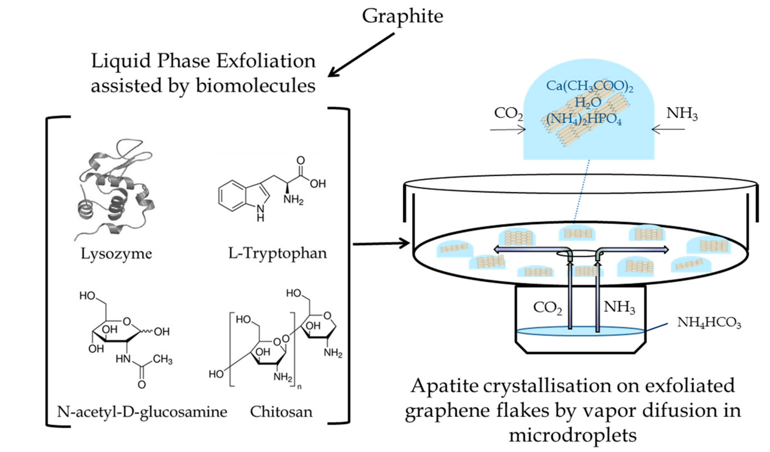
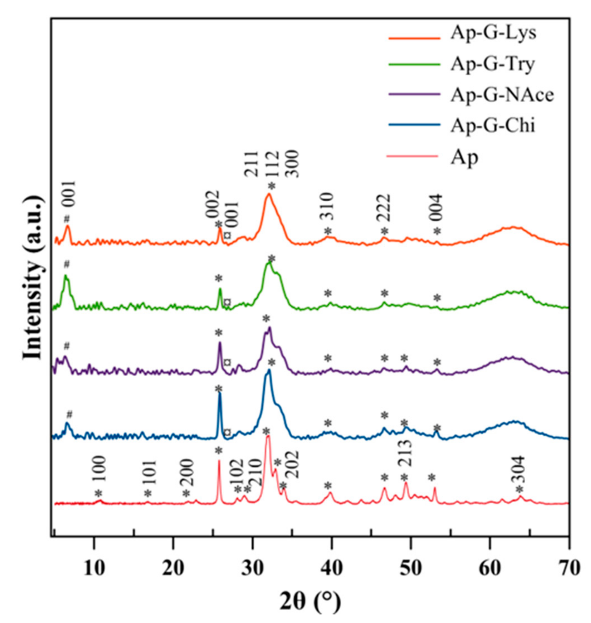
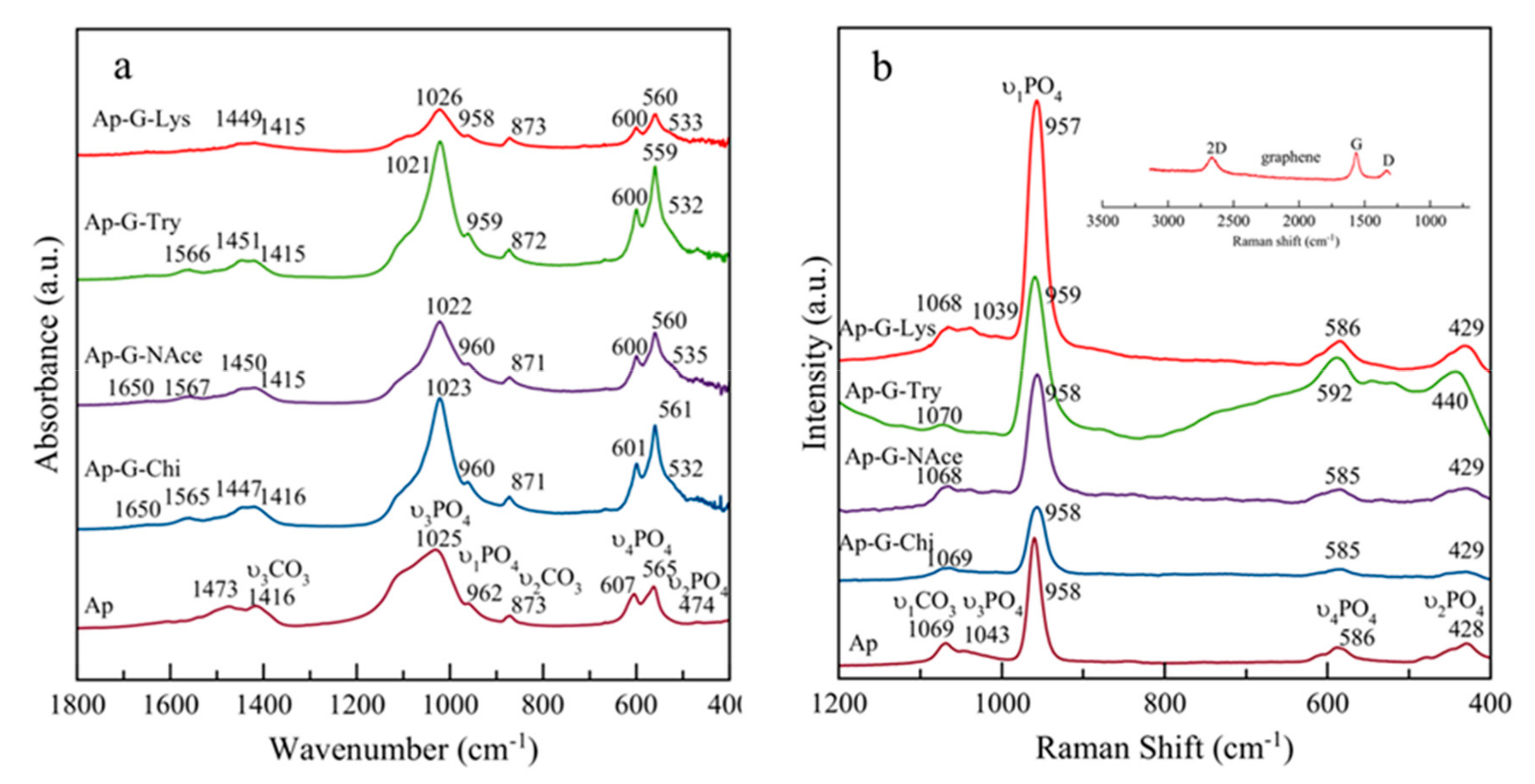
3.1. Crystallographic and Spectroscopic Features of the Nanocomposites

The XRD patterns of the samples precipitated in the presence of graphene nanoflakes prepared by the LPE technique in the presence of Chi, NAce, Try, and Lys are reported in Figure 2. All samples show rather similar patterns. They display the main distinguishing reflections of the apatite phase (PDF 01-1008), with peaks at 25.87° 2θ corresponding to the (002) plane; peaks at 31.77°, 32.19°, and 32.90° 2θ, corresponding to the planes (211), (112), and (300), respectively; reflections at 33.9° and 39.81° (planes (202) and 310), respectively); and other minor peaks in the 2θ range from 40–55°. For the sake of comparison, the XRD pattern of a sample of mature, nanocrystalline-carbonated apatite prepared by the citrate-based thermal decomplexing method [30] is plotted at the bottom of the graph. The reflections in the 2θ range of 31–34° are seen as a broad unresolved peak in all experiments, reflecting the nanocrystalline nature of the apatite particles.
The absence of octacalcium phosphate (OCP) in the samples is witnessed by the lack of its main reflection at 4.74°, or plane (100) (OCP, powder diffraction file PDF 44-0778). The OCP phase was found to be a precursor of experiments of precipitation of apatite by VDSD and gel methods, carried out in absence of supports [19,31], and precipitated and stabilized in the experiments performed in the presence of mica muscovite sheets [15]. These differences reveal that in the presence of functionalized graphene flakes in the crystallization media, the heterogeneous nucleation and growth of the apatite phase could be directly induced on the surface of the nanoflakes, without the precipitation of the precursor OCP phase; this event significantly modifies the progression of the apatite precipitation in respect to previous experiments [15,19].
On the other hand, the reflections at around 6–7° 2θ most likely correspond to the (001) basal plane of the exfoliated graphene, similar to what was found for graphite oxide (GO) [30]. The shift of this reflection from around 10° 2θ to lower angles (higher d-spacings) in the case of graphite oxide exfoliated in the presence of some polymers was reported to be caused by the increase in both the relative humidity and the concentration of polymers that intercalated the GO lattice. These authors found that at the higher polymer concentration used the GO appeared to be completely exfoliated, based on the absence of any d (001) peak [32]. In our experiments, the presence of the (001) reflection at lower angles reflects the intercalation of the used biomolecules, in addition to H2O, and the presence of a small peak at 26.6° 2θ would correspond to the (001) reflection of the residual, non-exfoliated graphite.
The characterization of the spectral features of the composites in the 1800–400 cm−1 range is shown in Figure 3a. The 4000–1800 cm−1 region (not shown) exhibits a broadband between 3600 cm-1 and 2800 cm-1, corresponding to –OH stretching of adsorbed water, while no clear indication of apatitic –OH bands around 3580 cm−1 was found, as is usual for biomimetic apatites. The spectral region from 400 to 1800 cm−1 was analyzed in more detail, allowing the basic visualization of the spectral features of the apatitic part of the composite. Only a small band at around 1570 cm−1, related to NH2 bending vibration, and a band of negligible intensity at around 1650 cm−1, related to carboxamide O=C–NHR [33] in the spectra Ap–G–NAce and Ap–G–Chi, reveal the presence of the biopolymers. These bands are absent in the FTIR spectrum of Ap. The main band at 1022–1026 cm−1 corresponds to the asymmetric stretching mode of PO43− groups (ν3PO4). The band at ~962 cm−1 is ascribed to the symmetric stretching (ν1PO4), while less intense bands at ~607 and 565 cm−1 are due to the bending mode of PO43− groups (ν4PO4). The band at ~532 cm−1 in the ν4PO4 domain can be assigned to non-apatitic (surface) HPO42− ions, which points to the biomimetic nature of the precipitated nanocrystalline apatite in these nanocomposites [34]. Finally, the small band at 474 cm−1 corresponds to the ν2PO4 mode. No clear indications of spectral features of graphene in the FTIR spectra could be observed.
In all FTIR spectra, the presence of carbonate (CO32−) bands was attested by vibrational signatures due to the ν3CO3 mode, with maxima around ~1416 cm−1 and 1473 cm−1, and the ν2CO3 mode, with a peak around 873 cm−1. The ν2CO3 region shows a broad peak distinctive of the different contributions characterizing different chemical environments of the CO3 group within the apatite structure, i.e., A- and B-type (with carbonate ions replacing OH and PO43− lattice ions, respectively) and labile carbonate species (belonging to the hydrated non-apatitic layer on the surface of nanocrystals) [35]. The existence of B-type substitutions was also witnessed by bands at 1515 and 1450 cm−1 [36].
Figure 3b shows the complementary characterization of the spectral features of the nanocomposites by Raman microspectroscopy in the 400–1200 cm-1 range, with a JASCO NRS-5100 Micro-Raman spectrometer (λexc = 532 nm). The spectral features of apatite arise at 957–959 cm–11PO4), 428 cm–12PO4), 586 cm–14PO4), and 1039–1043 cm–13PO4), with those of CO31CO3) arising at around 1069 cm-1; no clear indications of the spectral features of graphene could be observed, likely due to its low intensity compared to bands of apatite. Raman spectrometer coupled to the VPSEM microscope was necessary to reveal the characteristic D, G, and 2D signals of the graphene flakes at around 1330, 1560, and 2670 cm−1, respectively (Figure 3b, inset in red color). These bands displayed a 2D/G ratio lower than 1, and a full width at half maximum (FWHM) of the 2D band of 78 cm−1, indicating they are stacked in multiple layers (FWHM > 66 cm−1, > 5 layers) [37].

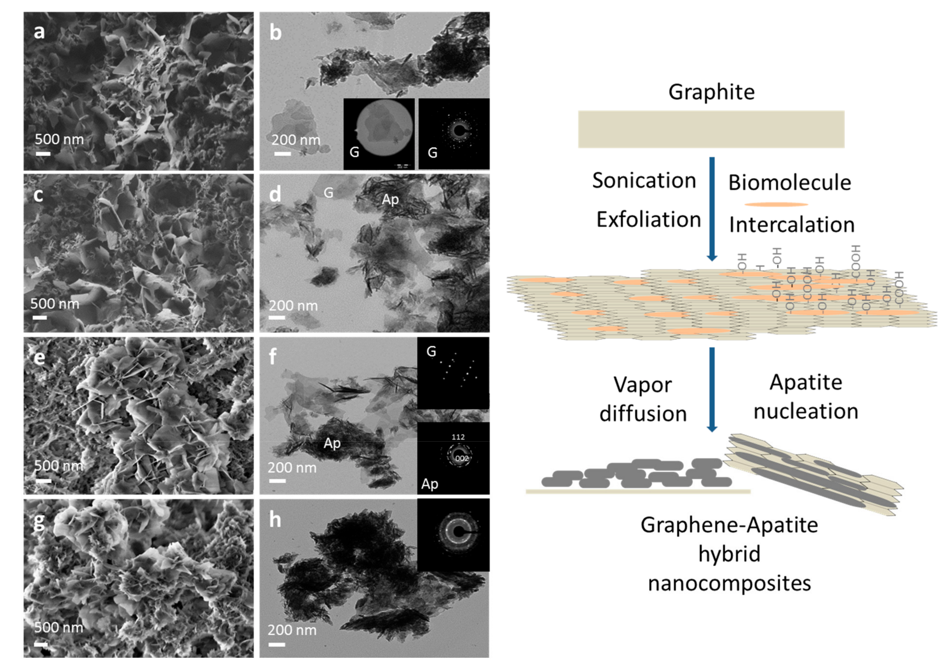
3.2. Morphological Characteristics of Hybrid Apatite–Graphene Nanocomposites

Figure 4a,c,e,g (left panel) shows the representative VPSEM micrographs of hybrid apatite–graphene nanocomposites, prepared with graphene nanoflakes and exfoliated in presence of Lys, Try, NAce, and Chi, respectively. Graphene flakes were visible at very low voltage (1–3 kV), while they become transparent to the electron beam at higher voltages. All samples were composed of a polydisperse population of flakes with an irregular shape, and nanocrystalline apatites with elongated shapes. The largest graphene flakes were produced in presence of Lys and Try (from 200–2000 nm), while the smallest ones were obtained in presence of NAce and Chi (200–800 nm). Only a few graphene flakes appeared greater than these sizes. In the last case, the composite was more homogeneous, with a more intimate apatite–graphene interaction and a closer spatial relationship. A more detailed size analysis is done in the TEM pictures (Figure 4b,d,f,h, on the left panel), where graphene flakes as large as 800–1000 nm can be observed in Figure 4b,d, prepared in presence of Lyz and Try, respectively.
In these pictures, the nanocrystalline apatites displayed the following average lengths (L) and widths (W): L = 105 ± 4 nm and W = 13 ± 2 nm for Lyz-exfoliated graphene and L = 152 ± 49 nm and W = 16 ± 5 nm for Try-exfoliated graphene. In Figure 4f, apatite nanoparticles (L = 90 ± 12 nm and W= 8 ± 3 nm) coating the graphene flakes exfoliated in presence of NAce and some isolated flakes are observed. The SAED patterns of both components, graphene (G) and apatite (Ap), are shown as insets in this micrograph. Summing up, the TEM pictures of these three composites reveal a heterogeneous distribution of apatite-coated graphene and free graphene flakes. Finally, the full coating with apatite nanoparticles (L = 69 ± 8 nm, W = 7 ± 3 nm) of the graphene flakes exfoliated in presence of chitosan (Figure 4h), confirms the greater impact of these Chi–graphene flakes on the homogeneity of the composite. As a general rule, the apatite nanoparticles always appeared as coating the graphene flakes, but this finding was more clearly evidenced when the sheets were exfoliated in the presence of chitosan.
These observations point to the functionalization of the flakes with different biomolecules during sonication. The labeling of the flakes with the biomolecules favors the stability of the graphene suspensions for time periods longer than 1 week, as well as the interaction between the graphene and the apatite nanoparticles during the early stages of nucleation at the surface–solution interfaces (see Figure 4, right panel). The biomolecules holding hydrophilic groups, such as –COOH, –OH, –NH2, =NH, or –NH–C=O–CH3 must be placed, not only intercalating the graphene layers of the flakes, but also being adsorbed on their surfaces, with some ionizable functional groups pointing toward the solution and providing electrostatic repulsion, thus preventing graphene from re-aggregation, as suggested when LPE is assisted by ionic surfactants [38]. These functional groups can act as nucleators of the calcium phosphate. The other mechanism of graphene stabilization is by steric repulsion. In addition to the electrostatic considerations, this mechanism should be envisaged in the case of the macromolecules employed in this paper. The better homogeneity of the Ap–G–Chi composites must be related to the more regular array of the nucleation points on the functionalized surfaces. Indeed, Chi is a polysaccharide (polymer of N-acetyl-glucosamine and D-glucosamine [39]) extremely rich in –OH groups, which forms sheets by the lateral aggregation of chains. In these sheets, one side exposes –NH2 groups (pKa ~ 6.5). At acidic pHs, Chi behaves as a polycation. However, at neutral to basic pHs, the –NH2 groups are uncharged and must be the anchoring points with the more hydrophobic graphene surface. The other side of Chi exposes –OH groups, which can act as nucleators. The detailed mechanism of graphite intercalation and graphene labeling with the different biomolecules deserves a deeper experimental investigation, which is out of the scope of this work.
On the other hand, the findings from X-ray diffraction and the morphological analysis point to the role of the “functionalized graphene” as a template that diminishes the energy barrier for nucleation, thus favoring the heterogeneous nucleation and the growth of the apatite on its surface, similarly to results reported by Liu et al. for the synthesis of apatite-reduced graphite oxide nanocomposites [12]. The presence of the template in the supersaturated solution can also explain why the apatite particles displayed nanosized dimensions. Indeed, the decrease of Gibbs free energy in a supersaturated system can be produced either by growth of the millions of nuclei or by primary aggregation of the early formed particles. If the second mechanism is active, as was reported by Iafisco et al. [40] when producing apatite in a Ca-citrate/phosphate/H2O system, the template might interact with the primary particles formed by heterogeneous nucleation, stabilizing them and thus minimizing their aggregation tendency and favoring the formation of nanoscale crystals, instead of larger crystals [19]. Therefore, the template effect can plausibly explain the formation of nanocrystalline apatites coating the graphene surfaces.

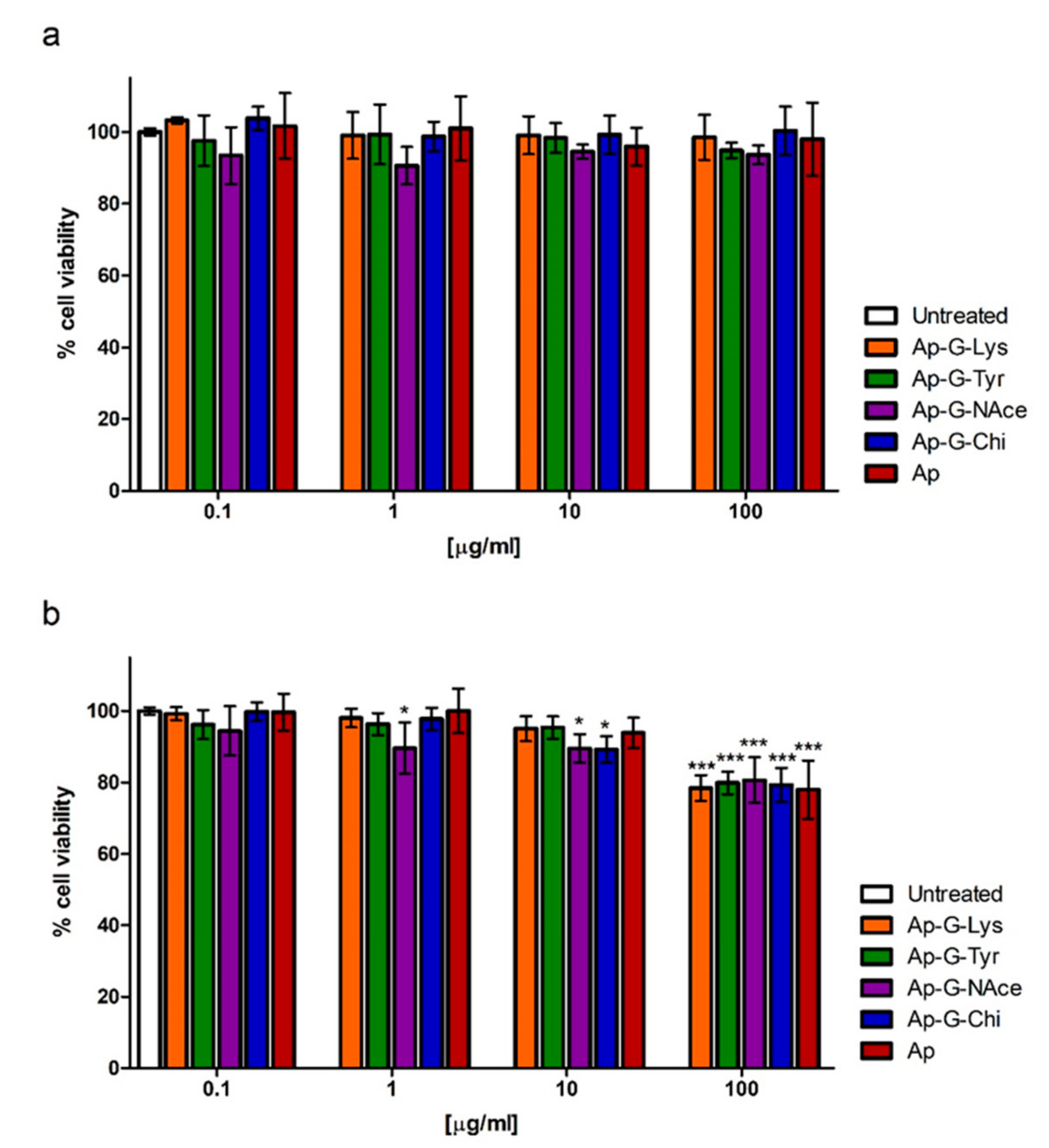
3.3. Cytocompatibility of Hybrid Nanocomposites

In view of the possibility of using these nanocomposites in future biomedical applications, their cytocompatibility was tested in an MTT assay on GTL-16 human carcinoma cells, after incubation at concentrations ranging from 0.1 to 100 μg/mL. No toxicity was observed on GTL-16 cells at any composite concentration, since in all cases full cell viability was observed (Figure 5). Furthermore, in view of using these nanocomposites for bone regenerative medicine, we tested their cytocompatibility also on the m17.ASC murine mesenchymal stem cell line, which has displayed osteogenic potential [29]. This cell line was somehow more sensitive to the contact with the graphene–apatite nanoparticles. Indeed, a certain level of toxicity was observed at the higher nanocomposite concentrations; however, in no case was viability lower than 80%, well above the 70% that is the cut-off indicated by ISO 10993-5:2009 [41].

4. Conclusions

In this research, the nucleation of apatite nanoparticles on exfoliated graphene flakes has been successfully carried out by the sitting drop vapor diffusion technique. The graphene flakes were prepared by the sonication-assisted liquid-phase exfoliation technique of graphite in the presence of lysozyme, L-tryptophan, N-acetyl-D-glucosamine, and chitosan as dispersing surfactants. They were stacked in multiple layers (>5 layers), and most likely intercalated and functionalized with the biomolecules. The apatite nanoparticles were found forming a coating on the graphene surfaces. When using Lys-, Try-, and NAce-exfoliated graphene, the apatite–graphene composites displayed a heterogeneous distribution of apatite-coated graphene and free graphene flakes, while more homogeneous composites were obtained when using Chi-exfoliated graphene flakes. The cytocompatibility tests were performed in a dose-dependent manner on GTL-16 cells, a human gastric carcinoma cell line, and on m17.ASC cells, a murine mesenchymal stem cell line with osteogenic potential. These tests revealed that in all cases, these nanocomposites are fully cytocompatible.

Author Contributions

Conceptualization, J.G.-M. and G.F.; Investigation, J.G.-M., L.A.G.-R., R.F.P., F.O., M.P., and C.V.-E.; Methodology, J.G.-M. and G.F.; Supervision, J.G.-M.; Writing (original draft), J.G.-M., G.F.

Funding

Grant numbers MAT2014-60533-R and PGC2018-102047-B-I00 (MCIU/AEI/FEDER, UE).

Acknowledgments

The authors acknowledge the projects MAT2014-60533-R and PGC2018-102047-B-I00, funded by Agencia Estatal de Investigación of the Spanish Ministerio de Ciencia, Innovación y Universidades, co-funded by European Regional Development Fund (FEDER, UE), and a grant from the Università del Piemonte Orientale A. Avogadro, Italy to M.P. The Scientific Instrumentation Centre of the University of Granada is also acknowledged for technical assistance in SEM, TEM, FTIR and Raman spectroscopy. C.V.-E. acknowledges Spanish MINEICO for his PTA2015-11103-I contract.

Conflicts of Interest

The authors declare no conflict of interest. The funding sponsors had no role in the design of the study; in the collection, analyses, or interpretation of data; in the writing of the manuscript, and in the decision to publish the results.

References

  1. Li, M.; Xiong, P.; Yan, F.; Li, S.; Ren, C.; Yin, Z.; Li, A.; Li, H.; Ji, X.; Zheng, Y.; et al. An overview of graphene-based hydroxyapatite composites for orthopedic applications. Bioact. Mater. 2018, 3, 1–18. [Google Scholar] [CrossRef] [PubMed]
  2. Gómez–Morales, J.; Iafisco, M.; Delgado–López, J.M.; Sarda, S.; Druet, C. Progress on the preparation of nanocrystalline apatites and surface characterization: Overview of fundamental and applied aspects. Prog. Cryst. Growth Charact. Mater. 2013, 59, 1–46. [Google Scholar] [CrossRef] [Green Version]
  3. De Groot, K.; Geesink, R.; Klein, C.P.A.T.; Serekian, P. Plasma sprayed coatings of hydroxylapatite. J. Biomed. Mater. Res. 1987, 21, 1375–1381. [Google Scholar] [CrossRef] [PubMed]
  4. Pichugin, V.F.; Eshenko, E.V.; Surmenev, R.A.; Shesterikov, E.V.; Tverdokhlebov, S.I.; Ryabtseva, M.A.; Sokhoreva, V.V.; Khlusov, I.A. Application of high-frequency magnetron sputtering to deposit thin calcium-phosphate biocompatible coatings on a Titanium surface. J. Surf. Invest. X.-ray, Synchr. Neutr. Tech. 2007, 1, 679–682. [Google Scholar] [CrossRef]
  5. Asri, R.I.M.; Harun, W.S.W.; Hassan, M.A.; Ghan, S.A.C.; Buyong, Z. A review of hydroxyapatite-based coating techniques: Sol–gel and electrochemical depositions on biocompatible metals. J. Mechan. Behav. Biomed. Mater. 2016, 57, 95–108. [Google Scholar] [CrossRef] [PubMed]
  6. Iafisco, M.; Bosco, R.; Leeuwenburgh, R.S.C.G.; van den Beucken, J.J.J.P.; Jansen, J.A.; Prat, M.; Roveri, N. Electrostatic spray deposition of biomimetic nanocrystalline apatite coatings onto titanium. Adv. Eng. Mater. 2012, 14, B13–B20. [Google Scholar] [CrossRef]
  7. Gómez-Morales, J.; Rodríguez-Clemente, R.; Armas, B.; Combescure, C.; Berjoan, R.; Cubo, J.; Martínez, E.; García-Carmona, J.; Garelik, S.; Murtra, J.; et al. Controlled nucleation and growth of thin hydroxyapatite layers on titanium implants by using induction heating technique. Langmuir 2004, 20, 5174–5178. [Google Scholar] [CrossRef]
  8. Zhou, S.; Zheng, X.; Yu, X.; Wang, J.; Weng, J.; Li, X.; Feng, B.; Yin, M. Hydrogen Bonding Interaction of Poly(d,l-Lactide)/hydroxyapatite nanocomposites. Chem. Mater. 2007, 19, 247–253. [Google Scholar] [CrossRef]
  9. Kim, J.-W.; Shin, K.-H.; Koh, Y.-H.; Hah, M.J.; Moon, J.; Kim, H.-E. Production of Poly(ε--Caprolactone)/Hydroxyapatite Composite Scaffolds with a Tailored Macro/Micro-Porous Structure, High Mechanical Properties, and Excellent Bioactivity. Materials 2017, 10, 1123. [Google Scholar] [CrossRef]
  10. Li, J.; Fartash, B.; Hermansson, L. Hydroxyapatite-alumina composites and bone-bonding. Biomaterials. 1995, 16, 417–422. [Google Scholar] [CrossRef]
  11. White, A.A.; Best, S.M. Hydroxyapatite–carbon nanotube composites for biomedical applications: A review. Int. J. Appl. Ceram. Technol. 2007, 4, 1–13. [Google Scholar] [CrossRef]
  12. Liu, Y.; Huang, J.; Li, H. Synthesis of hydroxyapatite–reduced graphite oxide nanocomposites for biomedical applications: Oriented nucleation and epitaxial growth of hydroxyapatite. J. Mater. Chem. B 2013, 1, 1826–1834. [Google Scholar] [CrossRef]
  13. Novoselov, K.S.; Geim, A.K.; Morozov, S.V.; Jiang, D.; Zhang, Y.; Dubonos, S.V.; Grigorieva, I.V.; Firsov, A.A. Electric field effect in atomically thin carbon films. Science 2004, 306, 666–669. [Google Scholar] [CrossRef] [PubMed]
  14. Lee, C.; Wei, X.; Kysar, J.; Hone, V. Measurement of the elastic properties and intrinsic strength of monolayer graphene. Science 2008, 321, 385–388. [Google Scholar] [CrossRef] [PubMed]
  15. Westervelt, R.M. Graphene nanoelectronics. Science 2008, 320, 324–325. [Google Scholar] [CrossRef] [PubMed]
  16. Nayak, T.R.; Andersen, H.; Makam, V.S.; Khaw, C.; Bae, S.; Xu, X.; Ee, P.L.R.; Ahn, J.H.; Hong, B.H.; Pastorin, G.; et al. Graphene for controlled and accelerated osteogenic differentiation of human mesenchymal stem cells. ACS Nano 2011, 5, 4670–4678. [Google Scholar] [CrossRef]
  17. Kalbacova, M.; Broz, A.; Kong, J.; Kalbac, M. Graphene substrates promote adherence of human osteoblasts and mesenchymal stromal cells. Carbon 2010, 48, 4323–4329. [Google Scholar] [CrossRef]
  18. Yang, K.; Gong, H.; Shi, X.; Wan, J.; Zhang, Y.; Liu, Z. In vivo biodistribution and toxicology of functionalized nano-graphene oxide in mice after oral and intraperitoneal administration. Biomaterials 2013, 34, 2787–2795. [Google Scholar] [CrossRef]
  19. Iafisco, M.; Gomez-Morales, J.; Hernandez-Hernandez, M.A.; García-Ruiz, J.M.; Roveri, N. Biomimetic Carbonate–Hydroxyapatite Nanocrystals Prepared by Vapor Diffusion. Adv. Eng. Mater. 2010, 12, 218–223. [Google Scholar]
  20. Gomez-Morales, J.; Delgado-Lopez, J.M.; Iafisco, M.; Hernandez-Hernandez, M.A.; Prat, M. Amino acidic control of calcium phosphate precipitation by using the vapor diffusion method in microdroplets. Cryst. Growth Des. 2011, 11, 4802–4809. [Google Scholar] [CrossRef]
  21. Nassif, N.; Martineau, F.; Syzgantseva, O.; Gobeaux, F.; Willinger, M.; Coradin, T.; Cassaignon, S.; Azais, T.; Giraud-Guille, M.M. In Vivo Inspired Conditions to Synthesize Biomimetic Hydroxyapatite. Chem. Mater. 2010, 22, 3653–3663. [Google Scholar] [CrossRef]
  22. Gomez-Morales, J.; Hernandez-Hernandez, A.; Sazaki, G.; Garcia-Ruiz, J.M. Nucleation and Polymorphism of Calcium Carbonate by a Vapor Diffusion Sitting Drop Crystallization Technique. Cryst. Growth Des. 2010, 10, 963–969. [Google Scholar] [CrossRef]
  23. Hernandez-Hernandez, A.; Rodriguez-Navarro, A.B.; Gomez-Morales, J.; Jimenez-Lopez, C.; Nys, Y.; Garcia-Ruiz, J.M. Influence of model globular proteins with different isoelectric points on the precipitation of calcium carbonate. Cryst. Growth Des. 2008, 8, 1495–1502. [Google Scholar] [CrossRef]
  24. Hernandez-Hernandez, A.; Gómez-Morales, J.; Rodriguez-Navarro, A.B.; Gautron, J.; Nys, Y.; Garcia-Ruiz, J.M. Identification of some active proteins on the process of hen eggshell formation. Cryst. Growth Des. 2008, 8, 4330–4339. [Google Scholar] [CrossRef]
  25. Calvaresi, M.; DiGiosia, M.; Ianiro, A.; Valle, F.; Fermani, S.; Polishchuk, I.; Pokroy, B.; Falini, G. Morphological changes of calcite single crystals induced by graphene–biomolecule adducts. J. Cryst. Growth 2017, 457, 356–361. [Google Scholar] [CrossRef]
  26. Gómez-Morales, J.; Verdugo-Escamilla, C.; Gavira-Gallardo, J.A. Bioinspired calcium phosphate coated mica sheets by vapor diffusion and its effects on lysozyme assembly and crystallization. Cryst. Growth Des. 2016, 16, 5150–5158. [Google Scholar] [CrossRef]
  27. Ciesielski, A.; Samori, P. Graphene via sonication assisted liquid-phase exfoliation. Chem. Soc. Rev. 2014, 43, 381–398. [Google Scholar] [CrossRef]
  28. Giordano, S.; Ponzetto, C.; Di Renzo, M.F.; Cooper, C.S.; Comoglio, P.M. Tyrosine kinase receptor indistinguishable from the c-met protein. Nature 1989, 339, 155–156. [Google Scholar] [CrossRef]
  29. Zamperone, A.; Pietronave, S.; Merlin, S.; Colangelo, D.; Ranaldo, G.; Medico, E.; di Scipio, F.; Berta, G.N.; Follenzi, A.; Prat, M. Isolation and characterization of a spontaneously immortalized multipotent mesenchymal cell line derived from mouse subcutaneous adipose tissue. Stem Cells Dev. 2013, 22, 2873–2884. [Google Scholar] [CrossRef]
  30. Delgado-Lopez, J.M.; Iafisco, M.; Rodriguez-Ruiz, I.; Tampieri, A.; Prat, M.; Gómez–Morales, J. Crystallization of bioinspired citrate-functionalized nanoapatite with tailored carbonate content. Acta Biomater. 2012, 8, 3491–3499. [Google Scholar] [CrossRef]
  31. Iafisco, M.; Marchetti, M.; Gómez-Morales, J.; Hernández-Hernández, M.A.; García-Ruiz, J.M.; Roveri, N. Silica gel template for calcium phosphates crystallization. Cryst. Growth Des. 2009, 9, 4912–4921. [Google Scholar] [CrossRef]
  32. Blanton, T.N.; Majumdar, D. X-ray diffraction characterization of polymer intercalated graphite oxide. Powder Diffr. 2012, 27, 104–107. [Google Scholar] [CrossRef] [Green Version]
  33. Kadir, M.F.Z.; Aspanut, Z.; Majid, S.R.; Arof, A.K. FTIR studies of plasticized poly(vinylalcohol)–chitosan blend doped with NH4NO3 polymer electrolyte membrane. Spectrochim. Acta Mol. Biomol. Spectros. 2011, 78, 1068–1074. [Google Scholar] [CrossRef] [PubMed]
  34. Vandecandelaere, N.; Rey, C.; Drouet, C. Biomimetic apatite-based biomaterials: On the critical impact of synthesis and postsynthetic parameters. J. Mater. Sci. Mater. Med. 2012, 23, 2593–2606. [Google Scholar] [CrossRef] [PubMed]
  35. Rey, C.; Combes, C.; Drouet, C.; Grossin, D. Comprehensive Biomaterials 2014, 187–221.
  36. Antonakos, A.; Liarokapis, E.; Leventouri, T. Micro-Raman and FTIR studies ofsynthetic and natural apatites. Biomaterials 2007, 28, 3043–3054. [Google Scholar] [CrossRef] [PubMed]
  37. Hao, Y.; Wang, Y.; Wang, L.; Ni, Z.; Wang, Z.; Wang, R.; Koo, C.K.; Shen, Z.; Thong, J.T.L. Probing layer number and stacking order of few-layer graphene by Raman spectroscopy. Small 2010, 6, 195–200. [Google Scholar] [CrossRef]
  38. Guardia, L.; Fernandez-Merino, M.J.; Paredes, J.I.; Solis-Fernandez, P.; Villar Rodil, S.; Martinez-Alonso, A.; Tascon, J.M.D. High-throughput production of pristine graphene in an aqueous dispersion assisted by non-ionic surfactants. Carbon 2011, 49, 1653–1662. [Google Scholar] [CrossRef]
  39. Nilsen-Nygaard, J.; Strand, S.P.; Vårum, K.M.; Draget, K.I.; Nordgård, C.T. Chitosan: Gels and Interfacial Properties. Polymers 2015, 7, 552–579. [Google Scholar] [CrossRef] [Green Version]
  40. Iafisco, M.; Ramírez-Rodríguez, G.B.; Sakhno, Y.; Tampieri, A.; Martra, G.; Gómez-Morales, J.; Delgado-López, J.M. The growth mechanism of apatite nanocrystals assisted by citrate: Relevance to bone biomineralization. CrystEngComm 2015, 17, 507–515. [Google Scholar] [CrossRef]
  41. ISO 10993-5:2009. Biological Evaluation of Medical Devices—Part 5: Tests for In Vitro Cytotoxicity. Available online: https://www.iso.org/standard/36406.html (accessed on 22 December 2018).
Figure 1. Schema showing the preparation of graphene flakes by sonication-assisted liquid-phase exfoliation of graphite in the presence of either lysozyme (Lys), L-tryptophan (Try), N-acetyl-D-glucosamine (NAce), or chitosan (Chi), and the experiment of the mineralization of the graphene flakes with apatites implemented in a “crystallization mushroom”.
Crystals 09 00341 g001
Figure 2. X-ray diffraction (XRD) patterns of nanocrystalline apatite nucleated by the vapor diffusion sitting drop (VDSD) method on graphene nanoflakes prepared by liquid-phase exfoliation (LPE) in the presence of Lys, Try, NAcel and Chi. (*) denotes apatite, (#) denotes the (001) plane of graphene, and (¤) denotes the (001) plane of residual graphite.
Crystals 09 00341 g002
Figure 3. (a) FTIR spectra and (b) Raman spectra of nanocrystalline apatites nucleated by the VDSD method on graphene nanoflakes, prepared by the LPE method in the presence of Lys, Try, NAce, and Chi.
Crystals 09 00341 g003
Figure 4. Left panel. (a,c,e,g) VPSEM and (b,d,f,h) TEM micrographs of nanocrystalline apatites nucleated by the VDSD method on graphene nanoflakes, prepared by liquid phase exfoliation in presence of Lys (a,b), Try (c,d), NAce (e,f), and Chi (g,h). Insets in the TEM micrographs are the selected area electron diffraction (SAED) patterns of the graphene flakes (G) and of the apatite (Ap). Right panel. Schematic illustration showing the formation process of graphene–apatite hybrid nanocomposites.
Crystals 09 00341 g004
Figure 5. Viability of GTL-16 cells (a) and m17.ASC cells (b) incubated with graphene–apatite biohybrid composites (Ap-G) for 72 hours in 3-(4,5-Dimethylthiazol-2-yl)-2,5-diphenyltetrazolium bromide (MTT) essays. The graphene flakes were prepared by the liquid-phase exfoliation method in presence of Lys, Try, NAce, and Chi. Data represent means ± SD of four independent experiments performed in triplicate, and statistical analyses were carried on using one-way ANOVA, with a Bonferroni comparison test. For statistical analysis, all data were compared to untreated samples.
Crystals 09 00341 g005

