Article

Field-Angle Dependence of Interlayer Magnetoresistance in Organic Dirac Electron System α-(BEDT-TTF)2I3

1
Department of Physics, Nagoya University, Furo-cho, Chikusa-ku, Nagoya 464-8602, Japan
2
Department of Physics, Toho University, Funabashi, Chiba 274-8510, Japan
*
Author to whom correspondence should be addressed.
Crystals 2019, 9(4), 212; https://doi.org/10.3390/cryst9040212
Submission received: 11 March 2019 / Revised: 11 April 2019 / Accepted: 16 April 2019 / Published: 19 April 2019
(This article belongs to the Special Issue Synthesis and Characterization of New Superconductors Materials)

Abstract

:
The effect of the Coulomb interaction in interlayer magnetoresistance is elucidated in collaboration with theory and experiments for the Dirac electron system in organic conductor α -(BEDT-TTF) 2 I 3 under a strong magnetic field. It is found that the effective g-factor enhanced by Coulomb interaction depends on the angle of the magnetic field, resulting in the field-angle dependence of a characteristic magnetic field in which interlayer resistance has a minimum due to spin splitting N = 0 Landau levels. The qualitative agreement between the theory and experimental results for the field-angle dependence of interlayer magnetoresistance is obtained.

1. Introduction

The electron correlation effects in two-dimensional Dirac electron systems have attracted much attention [1,2,3,4,5]. In the Dirac electron system of organic conductor α -(BEDT-TTF) 2 I 3 [6,7,8,9,10,11,12,13], it was shown that the electron correlation effects become a key factor to understanding electronic properties [14,15,16,17,18,19,20,21,22], since the Coulomb interaction is comparable with the band width. Moreover, the Fermi energy almost coincides with the Dirac point in α -(BEDT-TTF) 2 I 3 ; thus, any other energy bands do not overlap with Fermi energy [23,24]. α -(BEDT-TTF) 2 I 3 has a clean Dirac electron system, since the density of impurity is estimated to the ppm order [23,24]. These features are also advantageous to developing the physics of the correlated Dirac electron system.
The layered structure of α -(BEDT-TTF) 2 I 3 enables interlayer magnetoresistance measurements, which revealed the anomalous electronic properties of two-dimensional Dirac electron systems connected by weak interlayer tunneling [25,26,27,28,29,30]. In the magnetic field normal to the conductive layer, the energy of Landau levels in a massless Dirac electron system is expressed as E N = ± 2 e v F 2 | N | B , where , v F , N, and B denote the Planck constant, the Fermi velocity of the Dirac cone, the Landau index, and the magnetic-field strength, respectively. One of the characteristic features in these systems is the appearance of N = 0 Landau levels at the Dirac points. This effect was detected in interlayer magnetoresistance under a transverse magnetic field [25,26]. Interlayer magnetoresistance primarily depends on the interlayer tunneling of the Landau carriers, where Landau carriers indicate the carriers belonging to Landau levels that contribute to electric current. Note that in each Landau levels there are states with density proportional to B. Thus, the magnetic field creates mobile N = 0 Landau level carriers. The effect of the magnetic field appears only through the change of the N = 0 Landau level carrier density at the vicinity of the Dirac points. Thus, negative interlayer magnetoresistance due to the increase of the degeneracy of the N = 0 Landau levels was observed [25,26]. It was also shown that interlayer resistance has a minimum for g μ B B 0 / 2 / τ ~ due to the Zeeman splitting of the N = 0 Landau levels, where g, μ B , and τ ~ denote the g-factor, the Bohr magneton, and the relaxation time, respectively. If the electron correlation effects in the Landau levels are negligible, B 0 is independent of the angle of the magnetic field.
The electron correlation effects in the Landau levels, however, have been controversial. Although the possible ordered states due to Coulomb interaction, such as the valley-ordered state [31,32,33] and the interlayer spin-ordered state [34,35], were proposed, it was suggested that the anomalous increase of the spin lattice relaxation rate at low temperatures [33] can be explained by the spin transverse fluctuation in the absence of ordered states [36].
In the present study, we investigate the effects of the electron correlation between N = 0 Landau level carriers on interlayer magnetoresistance as a function of field-angle θ from the interlayer axis in collaboration with theory and experiment. The effective g-factor, g * , is treated using the mean field theory of the Coulomb interaction between the tilted Dirac electrons in the quantum limit. It is numerically shown that effective Coulomb interaction V HS , which enhances g * , is approximately proportional to ( B cos θ ) γ , where γ depends on the tilt of the Dirac cone. It is found that a characteristic magnetic field B 0 , at which the interlayer resistance has a minimum, depends on θ and temperature T, where the inverse of B 0 is proportional to cos θ approximately and the coefficient increases as T decreases. These results are in qualitative agreement with the experiment.

2. Method

2.1. Formulation

In α -(BEDT-TTF) 2 I 3 , there are two band-crossing points called Dirac points being assigned as the right (R) and left (L) valleys. The effective Hamiltonian describing the Dirac electron system in α -(BEDT-TTF) 2 I 3 is given by [10,31]
H = H 0 + H ,
where kinetic energy term H 0 is
H 0 = q γ γ τ s a r γ , τ s [ H ^ 0 τ s ] γ γ a r γ , τ s ,
H ^ 0 τ s = i τ v η x x i τ y x + i τ y η x ,
where a r γ , τ s and a r γ , τ s represent creation and annihilation operators, respectively, with two dimensional space r = ( x , y ) , Luttinger–Kohn base γ [10,37], valley τ = ± (R, L), and spin s = ± (↑, ↓). The degree of tilt η is defined by η = v 0 / v with cone velocity v and tilt velocity v 0 , where the anisotropy of the cone velocity is ignored here for simplicity [31]. The energy eigenvalue of H 0 is given by
E = v η k x ± k x 2 + k y 2 ,
with two-dimensional momentum k x and k y . The left inset in Figure 1 shows the tilted Dirac cone, where v ± v 0 are velocities in the ± k x directions, respectively. Interaction term H ^ is given by
H ^ = 1 2 d r d r V ( r r ) n ( r ) n ( r )
with long-range Coulomb interaction V ( r ) = e 2 / ε r and electron density operator n ( r ) .
The energy spectrum of the two-dimensional electronic system is quantized under a tilted magnetic field, B = × A = ( B x , B y , B z ) , given by the vector potential with the Landau gauge, A = ( B y z B z y , B x z , 0 ) . The Hamiltonian under the magnetic field is obtained by Peierls substitution i i + ( e / ) A and Zeeman energy E Z = g μ B B / 2 with B = | B | . The Landau levels are given by E N s = sgn ( N ) ( v / l ) 2 λ 3 | N | s E Z with λ = 1 η 2 and magnetic length l = / e | B z | . The wave function Ψ N , k τ ( r ) for the N = 0 Landau level is given by References [11,27,38]
Ψ N = 0 , k τ = + ( r ) = 1 2 ( 1 + λ ) η 1 + λ ϕ N = 0 , k ( r ) ,
Ψ N = 0 , k τ = ( r ) = 1 2 ( 1 + λ ) 1 λ η ϕ N = 0 , k ( r ) ,
where
ϕ N = 0 , k ( r ) = λ 1 / 4 2 π 1 π l 1 / 2 e i k x e Y ~ 2 / 2
with Y ~ = λ l ( y Y ) and center coordinate Y = l 2 k . When H = 5 T, E 1 3.5 meV using values of parameters for α -(BEDT-TTF) 2 I 3 , where velocity v = 1.0 × 10 5 m/s and v 0 = 0.8 × 10 5 m/s are given by the band calculation [10,23,31], 2 E Z 0.5 meV with g = 2 , l 14 nm.
In the present study, we consider the N = 0 Landau levels in order to study interlayer magnetoresistivity in the quantum limit and, for the case of E 1 E Z . The effective g-factor, g * , is treated by the mean field theory. The Green function G s ( k , i ε n ) is defined by
G s ( k , i ε n ) = 1 i ε n + μ + s E Z Σ s ,
where ϵ n = ( 2 n + 1 ) π / β is fermion Matsubara frequency with β = 1 / k B T and integer n, and μ is the chemical potential, determined so that the Fermi energy coincides with the Dirac point. The self-energy Σ s is given by self-consistent equation
Σ Σ = V HS m z ,
with effective Coulomb interaction V HS = τ [ V ( 0 ) ] τ , τ , τ , τ , magnetization m z = n n , and electron density for spin s, n s , where
Σ s = 1 D k 1 β ε n τ [ V ( 0 ) ] τ , τ , τ , τ G s ( k , i ε n )
and the Coulomb interaction matrix [ V ( q ) ] τ 1 τ 2 , τ 3 , τ 4 for the N = 0 Landau levels is given by
[ V ( q ) ] τ 1 τ 2 , τ 3 , τ 4 = 1 2 d r d r V ( r r ) × [ Ψ N = 0 , k + q τ 2 ( r ) · Ψ N = 0 , k τ 1 ( r ) ] [ Ψ N = 0 , k q τ 4 ( r ) · Ψ N = 0 , k τ 3 ( r ) ] ,
where the degeneracy of center coordinate D = L x L y / 2 π l 2 with length L x and L y in the x and y directions, respectively. The effective Coulomb interaction depends on magnetic length l, so effective Coulomb interaction depends on angle θ . Effective spin splitting E Z * is given by
E Z * = g * μ B B / 2 = E Z + Δ
with Δ = Σ = Σ 0 for the charge neutral system μ = 0 . Thus, effective g-factor g * is given by
g * = g + 2 Δ / μ B B .
Thus, the energy eigenvalues of N = 0 Landau levels are modified as follows:
E N = 0 , s = s E Z * = s ( E Z + Δ ) .
Interlayer conductivity is given by interlayer coupling as a perturbation [25]. The perturbation Hamiltonian H is given by
H ^ = 2 t c cos i c z 1 0 0 1
where t c and c represent interlayer transfer energy and interlayer spacing, respectively. In the quantum limit, N = 0 Landau levels are dominant in magnetotransport. The effective transfer energy between N = 0 Landau levels in neighboring layers is given by [25]:
t c ~ ( Y , z i ; Y , z i ) = t c × exp 1 4 c 2 e B x 2 + B y 2 | B z | × exp i e B x ( z i z i ) Y + Y 2 ,
where z i is the layer position, and the neighboring layers are z i = z i ± c . The center coordinate of initial state Y on one layer z = z i , and that of final state Y on neighboring layer z = z i ± c satisfy the condition
Y = Y ± B y B z c .
The complex interlayer conductivity σ ~ z z ( ω ) is given by [25]:
σ ~ z z ( ω ) = i L 2 Y , z i , τ , s ; Y , z i , τ , s N = 0 , Y , z i , τ , s | j ^ z | N = 0 , Y , z i , τ , s × N = 0 , Y , z i , τ , s | j ^ z | N = 0 , Y , z i , τ , s × f ( E N = 0 , s ) f ( E N = 0 , s ) E N = 0 , s E N = 0 , s 1 E N = 0 , s E N = 0 , s ω i / τ ~ ,
where τ ~ and j ^ z represent relaxation time and interlayer current density, respectively. The center coordinate Y is associated with wavenumber k by relation expression Y = l 2 k . Interlayer current density is given by j ^ z = ( e ) ( 1 / i ) [ z ^ , H ^ ] .
The leading term of real conductivity is given by [25]:
σ z z = 2 C t c 2 c e 3 τ ~ | B z | π 3 exp e c 2 ( B x 2 + B y 2 ) 2 | B z |
with
C = s τ D s τ ( E ) 2 d f d E d E
where D s τ ( E ) , t c and c denote density of states for spin s and valley τ , interlayer transfer energy, and interlayer spacing, respectively. Interlayer resistivity ρ z z is given by ρ z z 1 / σ z z , since interlayer Hall conductivities σ x z and σ y z are negligibly smaller than other components [39,40].

2.2. Experimental Method

2.2.1. Crystal Growth

Either the electrolysis method or the diffusion method are generally used in the crystal growth of organic conductors. We synthesized organic conductor α -(BEDT-TTF) 2 I 3 by the electrolysis method using an H-type cell. BEDT-TTF molecules and I 3 anions are desolved in a supporting electrolyte (THF, benzonitrile, chlorobenzene, etc.). Then, we supply electrical current (1∼5 μ A) between platinum electrodes. After about 1∼2 weeks, small single crystals appear on the positively based platinum electrode. The typical size of a crystal is 1 × 0.5 × 0.05 mm 3 .

2.2.2. Experiments of Interlayer Magnetoresistance Under Pressure

A sample with a dimension of approximately 0.7 × 0.5 × 0.05 mm 3 , on which four electrical leads (gold wire with a diameter of 15 μ m) are attached by carbon paste, is put in a Teflon capsule filled with the pressure medium (Idemitsu DN-oil 7373); then, the capsule is set in a NiCrAl clamp cell, and hydrostatic pressure of up to 1.7 GPa is applied. The hydrostatic pressure is determined at room temperature by a Manganine resistance gauge in the pressure cell. The interlayer resistance of a crystal is measured by a conventional DC method with an electrical current of 1 μ A along the c-crystal axis, which is normal to the two-dimensional plane. In the investigation, interlayer magnetoresistance is measured as functions of B and θ which is the angle between the magnetic-field direction and c-crystal axis at T = 0.5, 1.7, 2.5, 3.0, 3.5, and 4.2 K. As mentioned in the introduction, interlayer magnetoresistance is a useful tool to detect the effects of N = 0 Landau levels, including its Zeeman splittings.

3. Results

Figure 1 shows the theoretical results on | B cos θ | ( = | B z | ) dependences of effective Coulomb interaction V HS for tilt parameter η = 0 , 0.5 , 0.8 , and 0.9 . It is numerically shown that V HS | B cos θ | γ approximately for | B cos θ | > 3 . Effective Coulomb interaction depends on magnetic length l, which is a function of | B z | , as shown in Equation (12). Thus, effective Coulomb interaction depends on angle θ . The left inset shows the tilting Dirac cone, where v and v 0 represent cone velocity and tilt velocity, respectively. The right inset shows the η dependence of γ , where γ increases as η increases. Thus, we use a relation, V HS = u | B cos θ | γ , with γ = 0.87 for the tilted Dirac cones in α -(BEDT-TTF) 2 I 3 with η = 0.8 [23] hereafter. Parameter u = 0.3 is chosen to fit with the experimental results.
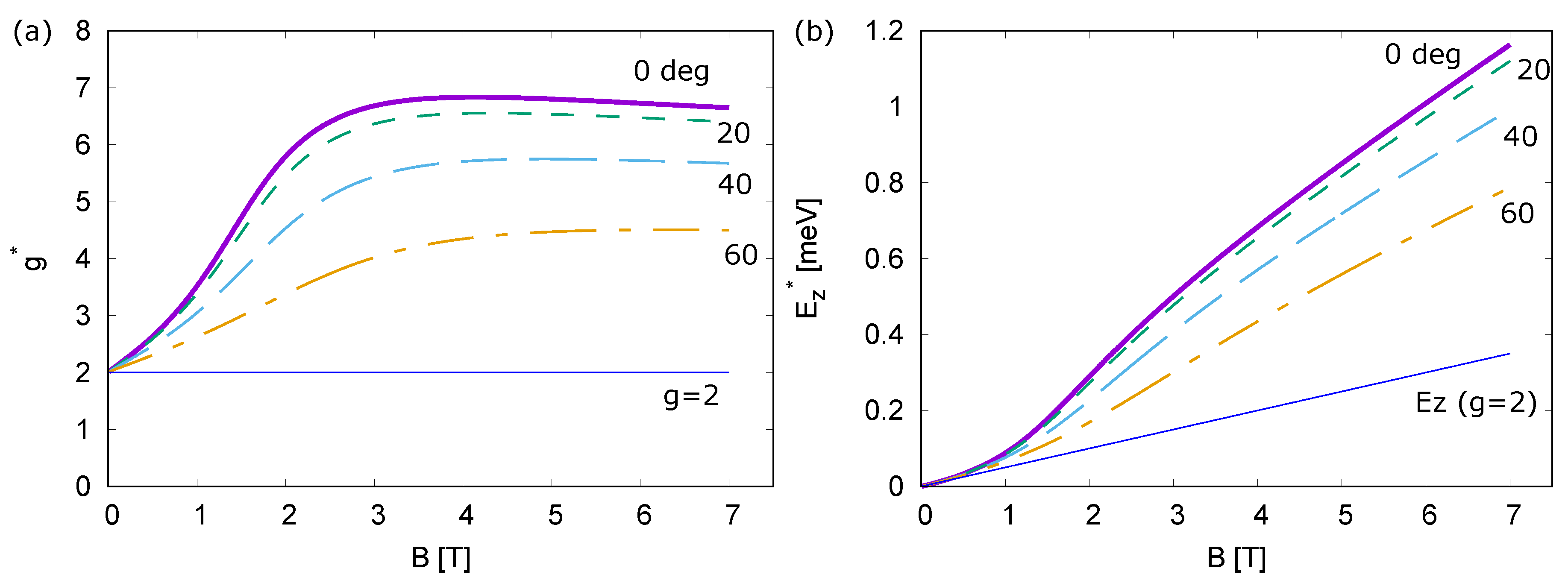
Figure 2a,b shows the theoretical results on the B-dependences of g * and E Z * , respectively, for θ = 0 , 20, 40, and 60 at T = 1.7 K. It is found that both g * and E Z * enhance by V HS depend on θ . When θ = 90 , g * = g and E Z * = E Z , since V HS = 0 . Although E Z * increases monotonically as B increases, g * has a maximum since Δ divided by B contributes to g * .
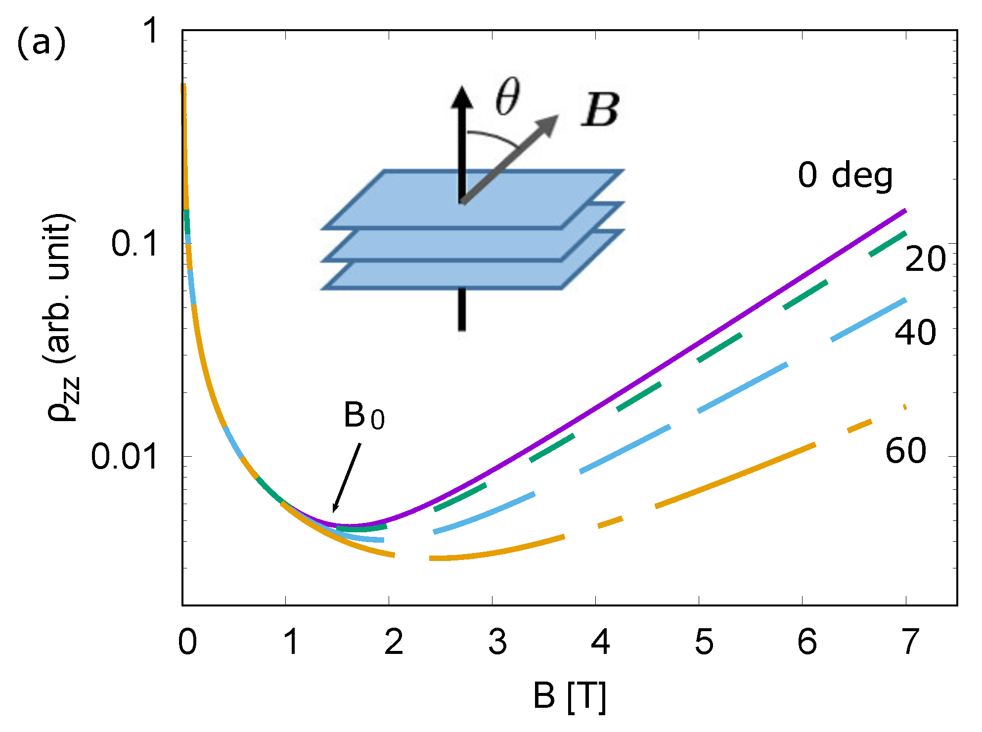
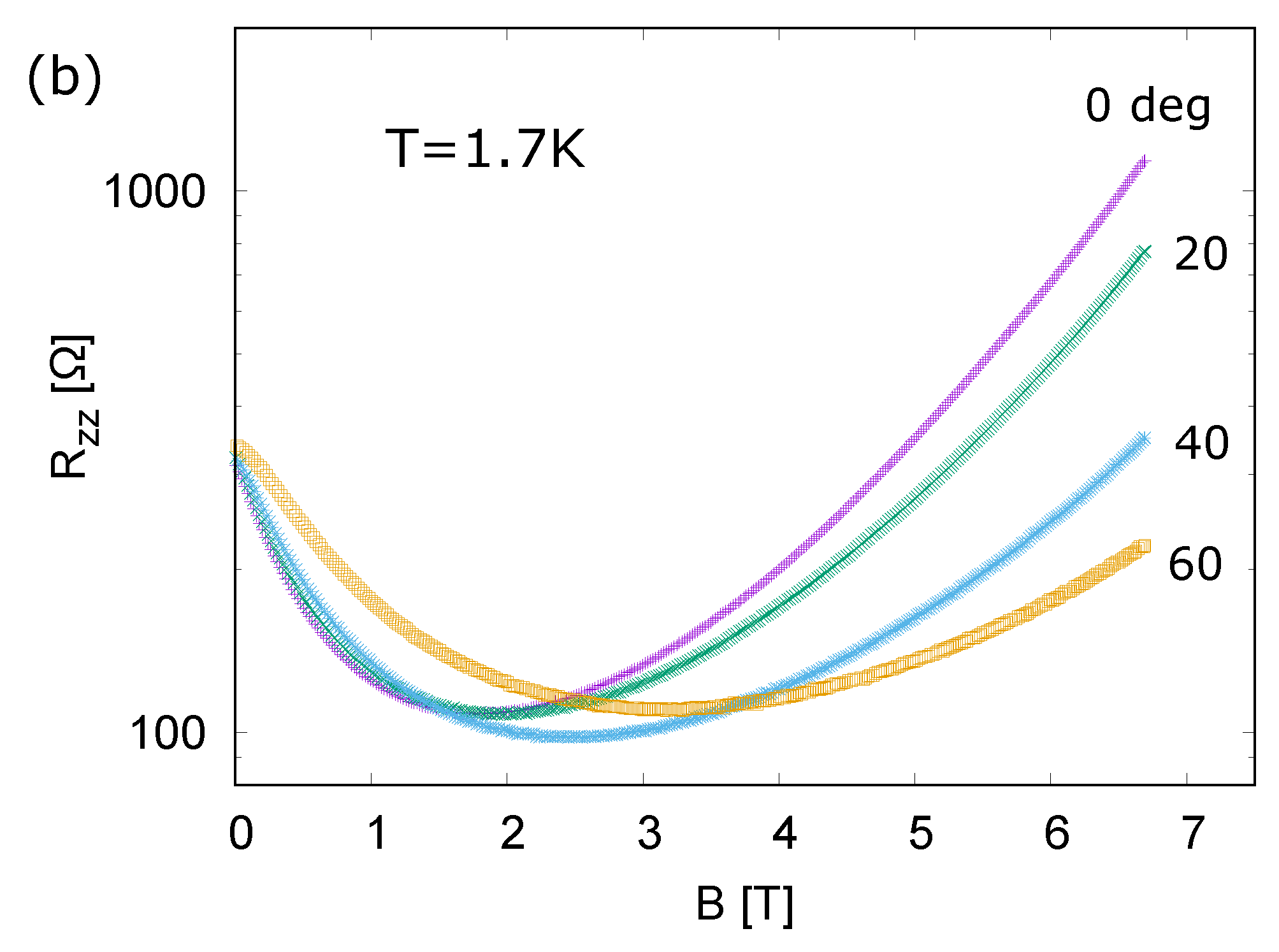
Figure 3a shows the theoretical results on B-dependences of interlayer resistivity ρ z z for θ = 0 , 20, 40, and 60 at T = 1.7 K. ρ z z has a minimum at B 0 . It is found that B 0 increases as θ increases due to θ -dependence of E Z * . Figure 3b shows the experimental results on B-dependences of interlayer resistance R z z for θ = 0 , 20, 40, and 60 at T = 1.7 K. B 0 obtained in the experimental results also increases as θ increases.
In a general two-dimensional system, E Z * dose not depend on θ . The agreement between the theory and experiment of interlayer magnetoresistance shown in Figure 3 indicates that effective Coulomb interaction plays an important role to the Zeeman effects. In the following, peculiar Zeeman effects in this system are examined.
The first step is to investigate g * for θ = 0 from the interlayer-magnetoresistance minimum, where g * μ B B 0 2 / τ ~ . Here, the rough of broadening energy / τ ~ of the Landau levels in this system is 3 K at low temperatures [32]. g * for θ = 0 is roughly estimated to be 5 experimentally at 1.7 K; this is close to the theoretical value, which is approximately 5.3 at B 0 1.8 T, as shown in Figure 2a.
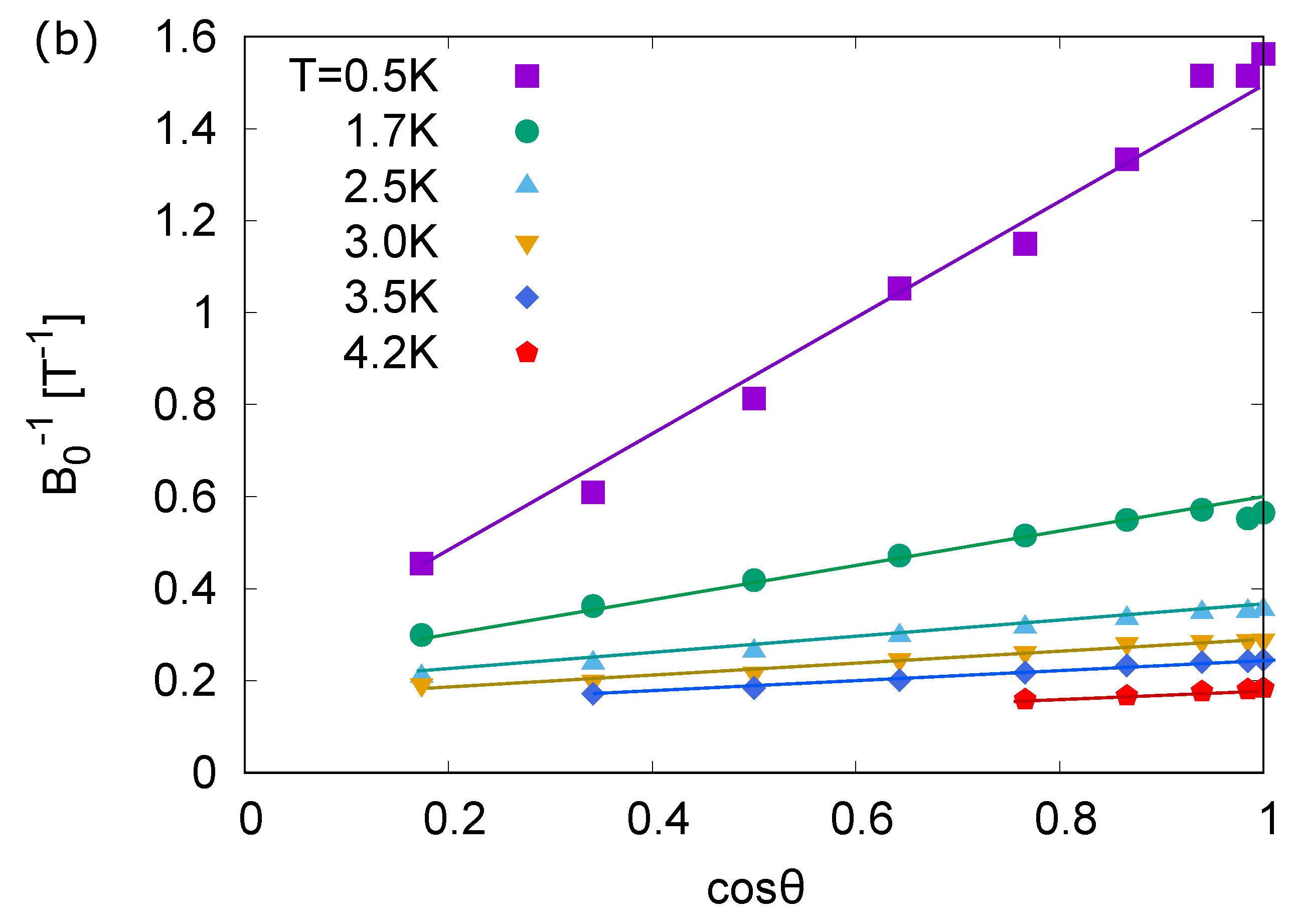
Lastly, the peculiar Zeeman effects on the θ -dependence of the interlayer magnetoresistance minimum are detected. In Figure 4a, the theoretical results on θ dependences of B 0 1 are drawn as functions of cos θ for T = 0.5 , 1.7 , 2.5 , 3.0 , 3.5 , and 4.2 K. It is numerically shown that 1 / B 0 a cos θ + b when θ is close to 0 . Note that this numerical calculation is not applicable when θ is close to 90 , where contributions of higher Landau levels in interlayer resistivity are not negligible. Figure 4b shows the experimental results on cos θ dependences of B 0 1 for T = 0.5 , 1.7 , 2.5 , 3.0 , 3.5 , and 4.2 K. The experimental results also show the same approximate relation on B 0 1 as a linear function of cos θ .
Figure 5 shows the theoretical and experimental results on T dependencies of coefficient a. It is found that coefficient a increases as T decreases, indicating remarkable θ dependence of B 0 1 at very low temperatures T 1.7 K. Those results show qualitative agreement between theory and experimental results for the field-angle dependence of interlayer magnetoresistance.

4. Discussion

Those theoretical curves in Figure 3a and Figure 4a qualitatively reproduce the experimental results including the characteristic features of the resistance minimum as shown in Figure 3b and Figure 4b. Here, the theoretical results do not coincide with the experimental results near B = 0 T, since only N = 0 Landau levels are examined in the present theoretical calculation. This theoretical approach, however, is valid because the special Landau-level structure in this system realizes the quantum limit in the magnetic field above 0.07 T for a perpendicular component to the two-dimensional plane at 1.7 K [32,41].
In the present study, the value of u for V HS is chosen to fit with the experimental results. The value of u will be evaluated by taking the Thomas–Fermi screening effect into account. The effects of the Coulomb interaction in N 0 Landau levels is also going to be studied in the mean field calculation. In addition, interlayer magnetoresistance is also going to be studied, taking N 0 Landau levels into account, which leads to the maximum of the interlayer resistance under weak magnetic fields [26,28].

5. Conclusions

In conclusion, the effect of the Coulomb interaction in interlayer magnetoresistance was elucidated in collaboration with theory and experiments for the Dirac electron system in organic conductor α -(BEDT-TTF) 2 I 3 . It was shown that enhancement of the effective g-factor due to the Coulomb interaction for N = 0 Landau levels depends on field angle θ . This was the key factor to explain the field-angle dependence of B 0 at which interlayer resistance has a minimum.
The value of the effective g-factor obtained in the present study at θ = 0 under a strong magnetic field is consistent with the theoretical and experimental results of the Nernst effect [42,43]. This is also consistent with the theoretical and experimental results of the spin-lattice relaxation rate [33,36]. The quantum Hall ferromagnetic state assumed in the present study supports the helical surface state [29].

Author Contributions

T.T. and A.K. conceived and designed the theories; T.T. and A.K. performed the numerical calculations and analyzed the data; N.T. performed the experiments and analyzed the data; T.T., N.T., and A.K. wrote the paper.

Funding

This work was supported by MEXT/JSPJ KAKENHI under Grant Nos. 15K05166, 18K18739, and 16H06346.

Acknowledgments

The authors would like to thank S. Hayashi for the fruitful discussions.

Conflicts of Interest

The authors declare no conflict of interest.

Abbreviations

The following abbreviations are used in this manuscript:
Rright
Lleft

References

  1. Goerbig, M.O. Electronic properties of graphene in a strong magnetic field. Rev. Mod. Phys. 2011, 83, 1193. [Google Scholar] [CrossRef]
  2. Suzumura, Y.; Kobayashi, A. Theory of Dirac Electrons in Organic Conductors. Crystals 2012, 2, 266. [Google Scholar] [CrossRef]
  3. Kotov, V.N.; Uchoa, B.; Pereira, V.M.; Guinea, F.; Castro Neto, A.H. Electron-Electron Interactions in Graphene: Current Status and Perspectives. Rev. Mod. Phys. 2012, 84, 1067. [Google Scholar] [CrossRef]
  4. Wehling, T.O.; Black-Schaffer, A.M.; Balatsky, A.V. Dirac materials. Adv. Phys. 2014, 63, 1. [Google Scholar] [CrossRef]
  5. Kajita, K.; Nishio, Y.; Tajima, N.; Suzumura, Y.; Kobayashi, A. Molecular Dirac Fermion Systems -Theoretical and Experimental Approaches-. J. Phys. Soc. Jpn. 2014, 83, 072002. [Google Scholar] [CrossRef]
  6. Kajita, K.; Ojiro, T.; Fujii, H.; Nishio, Y.; Kobayashi, H.; Kobayashi, A.; Kato, R. Magnetotransport Phenomena of α-Type (BEDT-TTF)2I3 under High Pressures. J. Phys. Soc. Jpn. 1992, 61, 23. [Google Scholar] [CrossRef]
  7. Tajima, N.; Tamura, M.; Nishio, Y.; Kajita, K.; Iye, Y. Transport Property of an Organic Conductor α-(BEDT-TTF)2I3 under High Pressure -Discovery of a Novel Type of Conductor-. J. Phys. Soc. Jpn. 2000, 69, 543. [Google Scholar] [CrossRef]
  8. Kobayashi, A.; Katayama, S.; Noguchi, K.; Suzumura, Y. Superconductivity in Charge Ordered Organic Conductor α-(ET)2I3 Salt. J. Phys. Soc. Jpn. 2004, 73, 3135. [Google Scholar] [CrossRef]
  9. Katayama, S.; Kobayashi, A.; Suzumura, Y. Pressure-Induced Zero-Gap Semiconducting State in Organic Conductor α-(BEDT-TTF)2I3 Salt. J. Phys. Soc. Jpn. 2006, 75, 054705. [Google Scholar] [CrossRef]
  10. Kobayashi, A.; Katayama, S.; Suzumura, Y.; Fukuyama, H. Massless Fermions in Organic Conductor. J. Phys. Soc. Jpn. 2007, 76, 034711. [Google Scholar] [CrossRef]
  11. Goerbig, M.O.; Fuchs, J.-N.; Montambaux, G.; Piechon, F. Tilted anisotropic Dirac cones in quinoid-type graphene and α-(BEDT-TTF)2I3. Phys. Rev. B 2008, 78, 045415. [Google Scholar] [CrossRef]
  12. Kobayashi, A.; Katayama, S.; Suzumura, Y. Theoretical study of the zero-gap organic conductor α-(BEDT-TTF)2I3. Sci. Technol. Adv. Mater. 2009, 10, 024309. [Google Scholar] [CrossRef]
  13. Tajima, N.; Kajita, K. Experimental study of organic zero-gap conductor α-(BEDT-TTF)2I3. Sci. Technol. Adv. Mater. 2009, 10, 024308. [Google Scholar] [CrossRef]
  14. Kino, H.; Fukuyama, H. Interrelationship among Electronic States of α-(ET)2I3, (ET)2MHg(SCN)4 and κ-(ET)2X. J. Phys. Soc. Jpn. 1995, 64, 4523. [Google Scholar] [CrossRef]
  15. Seo, H. Charge Ordering in Organic ET Compounds. J. Phys. Soc. Jpn. 2000, 69, 805. [Google Scholar] [CrossRef]
  16. Kobayashi, A.; Suzumura, Y.; Piechon, F.; Montambaux, G. Emergence of Dirac electron pair in the charge-ordered state of the organic conductor α-(BEDT-TTF)2I3. Phys. Rev. B 2011, 84, 075450. [Google Scholar] [CrossRef]
  17. Tanaka, Y.; Ogata, M. Correlation Effects on Charge Order and Zero-Gap State in the Organic Conductor α-(BEDT-TTF)2I3. J. Phys. Soc. Jpn. 2016, 85, 104706. [Google Scholar] [CrossRef]
  18. Hirata, M.; Ishikawa, K.; Miyagawa, K.; Tamura, M.; Berthier, C.; Basko, D.; Kobayashi, A.; Matsuno, G.; Kanoda, K. Observation of an anisotropic Dirac cone reshaping and ferrimagnetic spin polarization in an organic conductor. Nat. Commun. 2016, 7, 12666. [Google Scholar] [CrossRef]
  19. Matsuno, G.; Kobayashi, A. Effect of Interband Fluctuation on Spin Susceptibility in Molecular Dirac Fermion System α-(BEDT-TTF)2I3. J. Phys. Soc. Jpn. 2017, 86, 014705. [Google Scholar] [CrossRef]
  20. Hirata, M.; Ishikawa, K.; Matsuno, G.; Kobayashi, A.; Miyagawa, K.; Tamura, M.; Berthier, C.; Kanoda, K. Anomalous spin correlations and excitonic instability of interacting 2D Weyl fermions. Science 2017, 358, 1403. [Google Scholar] [CrossRef] [PubMed]
  21. Matsuno, G.; Kobayashi, A. Coexistence of Velocity Renormalization and Ferrimagnetic Fluctuation in the Organic Dirac Electron System α-(BEDT-TTF)2I3. J. Phys. Soc. Jpn. 2018, 87, 054706. [Google Scholar] [CrossRef]
  22. Ohki, D.; Matsuno, G.; Omori, Y.; Kobayashi, A. Optical Conductivity in a Two-Dimensional Extended Hubbard Model for an Organic Dirac Electron System α-(BEDT-TTF)2I3. Crystals 2018, 8, 137. [Google Scholar] [CrossRef]
  23. Kobayashi, A.; Suzumura, Y.; Fukuyama, H. Hall Effect and Orbital Diamagnetism in Zerogap State of Molecular Conductor α-(BEDT-TTF)2I3. J. Phys. Soc. Jpn. 2008, 77, 064718. [Google Scholar] [CrossRef]
  24. Tajima, N.; Kato, R.; Sugawara, S.; Nishio, Y.; Kajita, K. Interband effects of magnetic field on Hall conductivity in the multilayered massless Dirac fermion system α-(BEDT-TTF)2I3. Phys. Rev. B 2012, 85, 033401. [Google Scholar] [CrossRef]
  25. Osada, T. Negative Interlayer Magnetoresistance and Zero-Mode Landau Level in Multilayer Dirac Electron Systems. J. Phys. Soc. Jpn. 2008, 77, 084711. [Google Scholar] [CrossRef]
  26. Tajima, N.; Sugawara, S.; Kato, R.; Nishio, Y.; Kajita, K. Effect of the Zero-Mode Landau Level on Interlayer Magnetoresistance in Multilayer Massless Dirac Fermion Systems. Phys. Rev. Lett. 2013, 102, 176403. [Google Scholar] [CrossRef] [PubMed]
  27. Morinari, T.; Himura, T.; Tohyama, T. Possible Verification of Tilted Anisotropic Dirac Cone in α-(BEDT-TTF)2I3 Using Interlayer Magnetoresistance. J. Phys. Soc. Jpn. 2009, 78, 023704. [Google Scholar] [CrossRef]
  28. Morinari, T.; Tohyama, T. Crossover from Positive to Negative Interlayer Magnetoresistance in Multilayer Massless Dirac Fermion System with Non-Vertical Interlayer Tunneling. J. Phys. Soc. Jpn. 2010, 79, 044708. [Google Scholar] [CrossRef]
  29. Osada, T. Surface Transport in the ν = 0 Quantum Hall Ferromagnetic State in the Organic Dirac Fermion System. J. Phys. Soc. Jpn. 2015, 84, 053704. [Google Scholar] [CrossRef]
  30. Tajima, N.; Morinari, T. Tilted Dirac Cone Effect on Interlayer Magnetoresistance in α-(BEDT-TTF)2I3. J. Phys. Soc. Jpn. 2018, 87, 045002. [Google Scholar] [CrossRef]
  31. Kobayashi, A.; Suzumura, Y.; Fukuyama, H.; Goerbig, M.O. Tilted-Cone-Induced Easy-Plane Pseudo-Spin Ferromagnet and Kosterlitz Thouless Transition in Massless Dirac Fermions. J. Phys. Soc. Jpn. 2009, 78, 114711. [Google Scholar] [CrossRef]
  32. Tajima, N.; Sato, M.; Sugawara, S.; Kato, R.; Nishio, Y.; Kajita, K. Spin and valley splittings in multilayered massless Dirac fermion system. Phys. Rev. B 2010, 82, 121420(R). [Google Scholar] [CrossRef]
  33. Hirata, M. NMR Studies of Massless Dirac Fermions in the Quasi-Two-Dimensional Organic Conductor α-(BEDT-TTF)2I3. Ph.D. Thesis, The University of Tokyo, Tokyo, Japan, 2012. [Google Scholar]
  34. Kubo, K.; Morinari, T. Spin-Ordered States in Multilayer Massless Dirac Fermion Systems. J. Phys. Soc. Jpn. 2014, 83, 033702. [Google Scholar] [CrossRef]
  35. Kubo, K.; Morinari, T. Effect of Interlayer Spin-Flip Tunneling for Interlayer Magnetoresistance in Multilayer Massless Dirac Fermion Systems. J. Phys. Soc. Jpn. 2014, 83, 083701. [Google Scholar] [CrossRef]
  36. Tani, T.; Kobayashi, A. Spin-Lattice Relaxation Rate in Organic Dirac Electron System α-(BEDT-TTF)2I3 under Strong Magnetic Field. J. Phys. Soc. Jpn. 2019, 88. in press. [Google Scholar]
  37. Luttinger, J.M.; Kohn, W. Motion of Electrons and Holes in Perturbed Periodic Fields. Phys. Rev. 1955, 97, 869. [Google Scholar] [CrossRef]
  38. Sári, J.; Töke, C.; Goerbig, M.O. Magnetoplasmons of the tilted anisotropic Dirac cone material α-(BEDT-TTF)2I3. Phys. Rev. B 2014, 90, 155446. [Google Scholar] [CrossRef]
  39. Osada, T. Anomalous Interlayer Hall Effect in Multilayer Massless Dirac Fermion System at the Quantum Limit. J. Phys. Soc. Jpn. 2011, 80, 033708. [Google Scholar] [CrossRef]
  40. Osada, T. Magnetotransport in organic Diracfermion system at the quantum limit:Interlayer Hall effect and surfacetransport via helical edge states. Phys. Status Solidi 2012, 249, 962–966. [Google Scholar] [CrossRef]
  41. Sugawara, S.; Tamura, M.; Tajima, N.; Kato, R.; Sato, M.; Nishio, Y.; Kajita, K. Temperature Dependence of Inter-Layer Longitudinal Magnetoresistance in α-(BEDT-TTF)2I3: Positive versus Negative Contributions in a Tilted Dirac Cone System. J. Phys. Soc. Jpn. 2010, 79, 113704. [Google Scholar] [CrossRef]
  42. Proskurin, I.; Ogata, M. Thermoelectric Transport Coefficients for Massless Dirac Electrons in Quantum Limit. J. Phys. Soc. Jpn. 2013, 82, 063712. [Google Scholar] [CrossRef]
  43. Konoike, T.; Sato, M.; Uchida, K.; Osada, T. Anomalous Thermoelectric Transport and Giant Nernst Effect in Multilayered Massless Dirac Fermion System. J. Phys. Soc. Jpn. 2013, 82, 073601. [Google Scholar] [CrossRef]
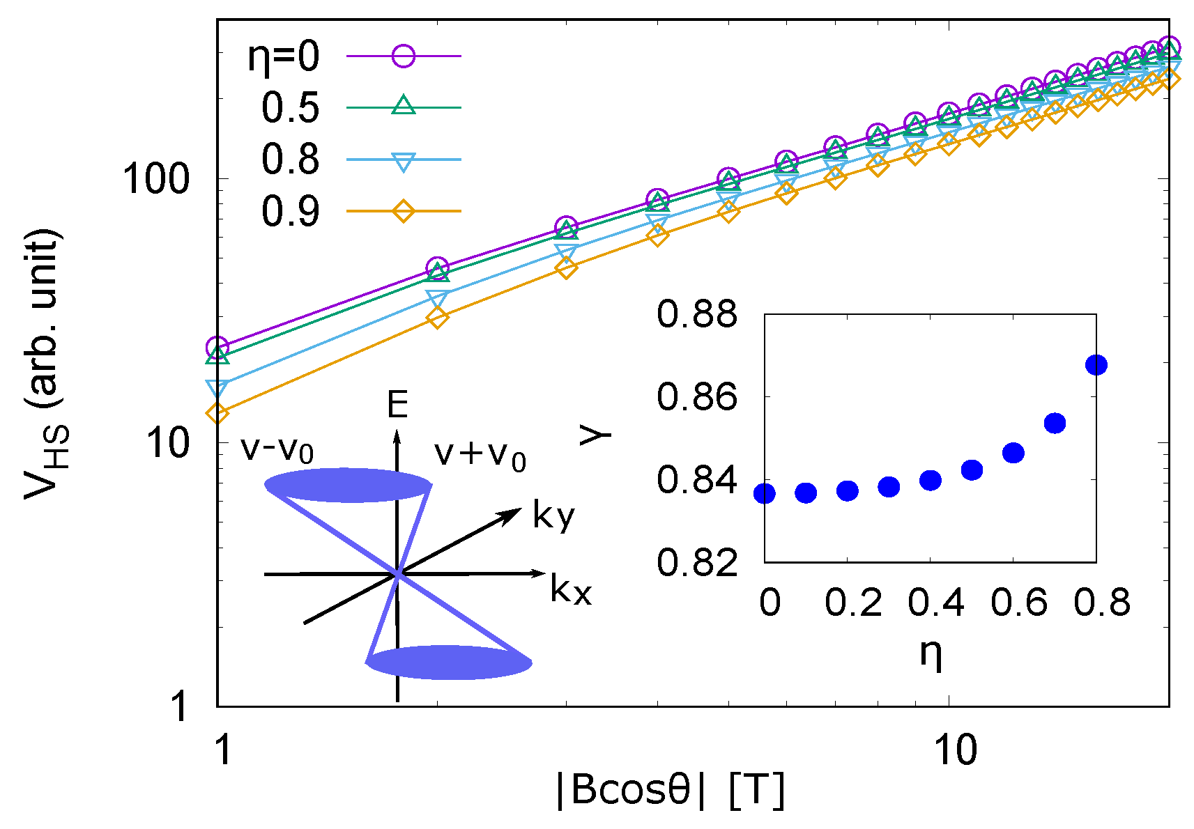
Figure 1. Theoretical results on | B cos θ | dependences of V HS for η = 0 (circle), 0.5 (triangle), 0.8 (inverted triangle), and 0.9 (diamond). The right inset shows the η dependence of γ . The left inset indicates the tilted Dirac cone, where v and v 0 are cone velocity and tilt velocity, respectively.
Crystals 09 00212 g001
Figure 2. Numerical results on B-dependences of g * (a) and E Z * (b), respectively, at T = 1.7 K for θ = 0 (solid line), 20 (dotted line), 40 (dashed line), and 60 (dot-dashed line). g and E Z in the absence of interaction are drawn by the thin solid line.
Crystals 09 00212 g002
Figure 3. (a) theoretical results on B-dependences of ρ z z for θ = 0 (solid line), 20 (dotted line), 40 (dashed line), and 60 (dot-dashed line) at T = 1.7 K. (b) experimental results on B-dependences of R z z for θ = 0 , 20, 40, and 60 at T = 1.7 K.
Crystals 09 00212 g003aCrystals 09 00212 g003b
Figure 4. (a) theoretical results on cos θ dependences of B 0 1 for T = 0.5 (open square), 1.7 (open circle), 2.5 (open triangle), 3.0 (inverted open triangle), 3.5 (open diamond), and 4.2 K (open pentagon). When cos θ is close to 1, numerical results show a relation 1 / B 0 a cos θ + b approximately, where a and b are independent of θ . (b) experimental results on cos θ dependences of B 0 1 for T = 0.5 (filled square), 1.7 (filled circle), 2.5 (filled triangle), 3.0 (inverted filled triangle), 3.5 (filled diamond), and 4.2 K (filled pentagon). As with the theoretical results, the experimental results show relation 1 / B 0 a cos θ + b approximately when cos θ is close to 1.
Crystals 09 00212 g004aCrystals 09 00212 g004b
Figure 5. Theoretical results (filled square) and experimental results (filled circle) of coefficient a as a function of T in relation 1 / B 0 a cos θ + b . Coefficient a increases as T decreases. Coefficient a especially rapidly increases at low temperatures. Theoretical and experimental results coincide.
Crystals 09 00212 g005